1
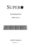
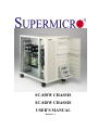
SC-830W CHASSIS
SC-820W CHASSIS
USER’S MANUAL
Revision 1.1
Chapter 1
SC830W/SC820W CHASSIS
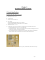
I. Chassis Specifications
Dimensions: 380 x 505 x 570 mm ( W x H x D)
A. Drive bay: 5.25” x 9, 3.5” x 2
B. 9 expansion slots
C. lockable side door and front door
D. Power Supply:
SC830W --Dual Redundant 300W ATX 2.03 compliant
SC820W-- Single Redundant Cooling 400W ATX 2.03 compliant
E. Maximum board size : 18” x 13”
F. Cooling system: Two sections of cooling. One cooling system for each chamber of the chassis.
1) On the Hard Disk Drive side—two of 12-cm exhaust fans.
2) On the Main board side – There are two cartridges on the front. Inside each cartridge, there are two
cooling fans. Each fan is 9-cm with 3-pin connector.
3) Two Fan deflectors and two fan door-blocks are also included. These deflectors are designed to
optimize airflow, and the fan-door blocks to prevent hot air from being drawn back.
H.
Parts included: Mounting kits, drive bay rails (11 pairs), rubber stands, cables and wires tie wraps.
Page 1
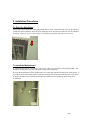
2. Installation Procedures
To Open the Side Doors:
Please locate 4 holes and a lock on the motherboard sides of chassis. Unscrew the four screws on the side door,
and the door will be unlocked. Move the doors slightly upward to open the door. Both side doors are unlocked
by default. However, if you lock one side door by using the key provided, both doors will be locked.
To Install the Motherboard:
A. Check if the I/O port fits your chassis I/O plate or not. (They are several kinds of I/O shield standards. The
default I/O for this chassis is Venus with punch out plug for the sound port.)
B. Check the mounting holes on the motherboard to see if they align with the mounting stands on the chassis. If
not, add or remove the mounting stands to match the mounting holes on the board with the holes on the chassis.
C. Remove the unnecessary mounting stands under the motherboard to avoid shorting the circuitry on the
motherboard.
Page 2
To Attach the Black Rubber Standoffs to the Inside Motherboard Tray to
Function as Shock Absorbers.
To prevent the motherboard from being damaged by impact, please peel off the double-sided tape of the rubber
standoffs and attach the black rubber standoffs on the motherboard tray at the locations under the CPU and PCI
slots. This is especially important for the Xeon systems.
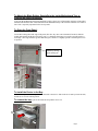
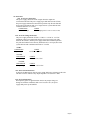
To Open the Front Panel:
Locate three locking tabs at the edge of the panel (The drive bay doors can be detached if needed.) Slide the
locking tabs upward and the door will swing open. To detach the front panel, you need to open the panel to a
wide angle (--the angle should be greater than 90 degrees) and move it slightly upward to slide the panel out of
its position.
Unlock by moving
up the locking tab
To Install the Device in the Bay:
All the drive bays need to have a pair of rails mounted to the device. Slide in the device until you hear the click,
and the device is in the locked position.
To remove the bay: squeeze the metal bars and pull the device out.
Page 3
To Install IDE , Floppy and SCSI Cables:
A. The chassis has eight cable access holes to enhance cable organization and to optimize airflow in the
chassis.
B. Locate eight cable holes inside the chassis. Route the cables through the closest cable access holes to the
best organize the cables and to increase airflow in the chassis.
To Install the Cooling Device:
All fan cartridges, fan deflectors and fan door blocks are designed to optimize ventilation inside the chassis. If
a cooling fan is not installed into the cooling fan slot, you need to install the door block in the slot to prevent
drawing hot air back into the motherboard side of the chassis.
For best ventilation, please keep both side-doors closed at all time.
Fan Door block
Dual Fan with cartridge
Page 4
To Adjust Airflow Directions
Two deflectors are designed to improve air circulation in the chassis. Loosen and tighten the screws on the
deflectors to redirect the airflow in the chassis. If needed, the deflectors also can be removed.
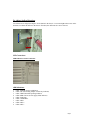
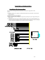
LED Connections
LED Indicators on the Front Panel
LED Definitions:
1. LED1: POWER (Power on Indicator)
2. LED2: NIC (Networking adapter card activity indicator)
3. LED3: HDD (Hard disk operating indicator)
4. LED4: PWR FAULT (Power supply failed indicator)
5. LED5: FAN FAIL
6. LED6: OVERHEAT
7. LED7: DEV 1
8. LED8: DEV 2
9. LED9: DEV 3
Page 5
Switches:
1. POWER: Power Switch
2. ALARM: ACPI Sleep Switch
3. RESET: Reset Switch
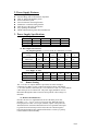
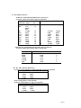
Front Panel LED PCB Pin Assignments
JP4 header
1 Power LED (Green) +
3 X Key
5 Power LED (Black)
7 Hard drive LED (Yellow) +
9 Hard drive LED (Black)
11 Power Switch (Green) +
13 Power Switch Ground (Black)
15 Reset Switch (White)
17 Reset Switch Ground (Black)
19 ACPI Switch (White)
21 ACPI Switch Ground (Black)
23 X
25 Overheat LED (Red) +
27 X
29 X
31 X
33 X
Pin 1 GND
Pin 1 GND
Pin 1 GND
JP5 : Device 1 LED
JP6 : Device 2 LED
JP7 : Device 3 LED
2 X
4 Fan Fail LED (Red) +
6 Fan Fail LED Ground (black)
8 Power Fail LED(Red) +
10 Power Fail LED Ground (black)
12 NIC Activity LED (Yellow) +
14 NIC Activity LED Ground (Black)
16 X
18 X
20 X
22 X
24 X
26 Overheat LED Ground (black)
28 Speaker (Red)
30 X
32 X
34 Speaker Ground (black)
{ Device 1,2,3 LED for system device LED }
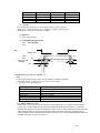
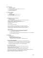
LEDs and Power and Reset wiring connections:
1.
2.
3.
4.
5.
6.
7.
8.
9.
10.
PWR LED
HDD
PW S
Reset
Switch
Fan Fail
Power Fail
NIC LED
O.H.
Speaker
: Pin 1 and Pin5 for System Power LED.
: Pin 7and Pin 9 for IDE hard drive activity.
: Pin 11 and Pin 13 for System Power On-Off switch .
: Pin 15 and Pin 17 for system reset switch.
: Pin 19 and Pin 21 for ACPI switch. ( momentary switch)
: Pin 4 and Pin 6 for system fan fail LED indication.
: Pin 8 and Pin 10 for Power fault LED indication.*
: Pin 12 and Pin 14 for system Network Activity LED indication.
: Pin 25 and Pin 26 for system Overheat LED indication.
: Pin 28 and Pin 34 for system Speaker.
* Power fail LED: It can be connected to power supply Power LED (Green/Black). Please check the ATX
Wiring harness diagram.
Page 6
CHAPTER 2: POWER SUPPLY
1. Installation: Hot-Swap procedures
Please refer to the following procedures should either one of your power supply units is found
defective.
A) Locate the defective power supply by examining the individual LED on the module, or the LED on the
system front panel.
B) Unscrew the defective power supply unit.
C) Remove the defective power supply unit.
D) Replace a bad unit with a new GOOD power supply unit by inserting a new power supply into the power
supply system.
E.) Check the DC OK LED-- the power supply status indicator. There are two DC OK LED Indicators, one
indicator for each power supply unit. If a power supply unit functions correctly, its indicator should light
up. If the indicator does not light up, then you need to fix the power supply unit.
Page 7
2. Power Supply Features
l
l
l
l
l
l
l
l
l
Hot-Swappable capability
Internal ORing diode for Redundancy Operation
Dual AC input for Redundancy safety
Power fault alarm system
Fan rail with noise decreasing function
Standard PC connection/wiring interface
Meet the up-to-date ATX specification
Easy operating and maintain
MTBF (Demonstrated) greater than 100,000 hours
3. Power Supply Specifications
3.1 Input Voltage
Parameter
Min
Voltage
90 VAC
Voltage
180 VAC
Frequency
47
Nor
115 VAC
230 VAC
Max
132 VAC
264 VAC
63
Units
Vrms
Vrms
Hz
3.2 DC Output Characteristics
3.21 Output Regulation To be met under all combinations of loading.
Output
V1
V2
V3
V4
V5
- Standby
Voltage
+5V
+3.3V
+12V
-5V
12V
5V
Max. Load
30A
15A
12A
0.5A
0.5A
1A
Min. Load
3A
0A
1A
0A
0A
0A
Max. Power
Load Reg. %
Line Reg. %
Total 150W
+/-5% +5/-3%
+/-1%
+/-1%
144W
+/-5%
+/-1%
2.5W
+/-10%
+/-1%
6W
+/-10%
+/-1%
5W
+/-5%
+/-1%
3.2.2 Ripple & Noise
Ripple & Noise
Ripple
Noise
3.3
%
%
+5V
+3.3V
+12V
-5V
-12V
+/-1%
+/-1%
+/-1%
+/-1%
+/-1%
+/-1%
+/-1%
+/-2%
+/-1%
+/-2%
Standby
5VSB
+/-1%
+/-1%
Remote Sensing
The +3.3V and +5V outputs shall have provisions for remote sensing to
compensate for 100mv of cable, connector & PCB trace drops. The default
+3.3V sensor shall be connected to pin 11 of Connector P1. The +5V sensor shall be
connected to pin 20 of Connector P1. The power supply shall draw no more
than 10mA through the remote sensor line to keep the DC offset voltage to a
minimum.
3.4 Remote ON/OFF(PS-ON)
PS-ON is an active low signal that turns on all of the main power rails,
including +3.3V,+ 5V,-5V,+12V & -12V power rails. When this signal is
held up by the PC board or is left open circuited, outputs of the power rails
should not deliver current and should be held at a zero potential with respect
to ground. Power should only be delivered to the rails if PS-ON signal is
held at ground potential. This signal should be held at +5VDC by a pull-up
resistor which is built in internally.
Page 8
Power On
ON
OFF
OFF
OFF
P1-PIN #14 PS-ON
L
H
X
X
Power Switch
ON
ON
ON
OFF
P1-PIN #14 PS-ON
IN
IN
OUT
X
3.5 +5V SB
The +5VSB output is always on (+5V Standby) when AC power is applied
and the power switch is turned on. The +5VSB line is capable of delivering at a
maximum of 1.5A for PC board circuit to operate.
3.6 Efficiency
65% min. at full load test.
3.7 Timing/Housekeeping/Control
3.7.1
PS-OK Signal
3.7.2
Off
PS-ON On
~
95%
10%
+5V/+3.3V O/P
PS-OK
T5
~
T4
T3
PW-OK Sense Level =95% of nominal T2
Note:
T2:The output voltage shall rise from <10% of nominal to within the regulation
specified in Section 2.2 within 0.1 to 20 ms.(0.1ms £T2 £20ms)
T3 T4 and T5 are as following Table:
Signal Type:
Logic level low
Logic level high
High state output impedance
PS-OK delay
PS-OK rise time
Power down warning
+5VDC,TTL compatible
<0.4V while sinking 4 mA
Between 2.4VDC and 5VDC output while sourcing 200mA
1KV from output to common
100ms < T3 < 500 ms
T5 £ 10 ms
T4 > 1 ms
3.7.2 PWR_OK(Power Good)
PWR_OK is a “power good” signal. It should be asserted high by the power supply to indicate that the
+5VDC and +3.3VDC outputs are above the undervoltage thresholds listed in Section 3.2 . PWR_OK
should be descended to a low state when either the +5VDC or the +3.3VDC output voltages falls below the
undervoltage threshold, or when the main power has been removed for a time long enough that power
supply operation cannot be guaranteed beyond the hold-up time. The electrical and timing characteristics of
the PWR_OK signal are given in Section 4.7.1.
Page 9
3.8 Protection
3.8.1 Over Power Protection
This power supply shut down all DC outputs when the outputs are
overloaded to the limit. The power supply logic shall latch into the off state,
the power supply shall return to the normal operation only after the fault has
been removed, and the PS-ON, or AC input, has been cycled OFF/ON with
a minimal OFF time of 1 second.
CONDITIONS
LIMITS
90/180VAC input
When output power is over to 110%~130%
3.8.2 Over the Voltage Protection
The power supply shall latch off if the +5 VDC or +3.3VDC or +12 VDC
maximum voltage exceeds the limits shown. The power supply logic shall
latch into the off state, and the power supply shall return to normal operation
only after the fault has been removed, and the PS-ON, or AC input, have been
cycled OFF/ON with a minimum OFF time of 1 second.
+5 VDC
CONDITIONS
All operating
LIMITS
5.6 VDC
6.5 VDC
+3.3 VDC
CONDITIONS
All operating
LIMITS
3.8 VDC
4.3 VDC
+12 VDC
CONDITIONS
All operating
LIMITS
13.6 VDC
15.6 VDC
3.8.3 Short Circuit Protection
A short circuit that has been placed on any output shall cause no damage to this unit.
The short circuit is defined as any output impedance of less than 0.1 ohms.
3.8.4 No Load Operation
When primary power is applied with no load on any output voltage, no
damage or hazardous conditions shall occur. In such a case , the power
supply shall power up and stabilize.
Page 10
3.9 DC Output connectors
20 PIN (For ATX motherboard Main Power Connector.)
Connector: Molex 39-01-2200 or approved equivalent.
Pin
Signal
18AWG Wire
18AWG Wire Signal
Pin
Orange
+3.3VDC
11
1
+3.3VDC
Orange
BRN.
+3.3V
11
default
sense
Blue
-12VDC
12
2
+3.3VDC
Orange
Black
COM
13
3
COM
Black
Green
PS-ON
14
4
+5VDC
Red
Black
COM
15
5
COM
Black
Black
COM
16
6
+5VDC
Red
Black
COM
17
7
COM
Black
White
-5VDC
18
8
PG
Gray
Red
+5VDC
19
9
+5VSB
Purple
Red
+5VDC
20
10
+12VDC
Yellow
6 PIN (P2) (For ATX motherboard Secondary Power Connector.)
Connector: Molex 90331-0010 or approved equivalent.
18 AWG Wire
Black
Black
Black
Orange
Orange
Red
Signal
COM
COM
COM
+3.3V
+3.3V
+5VDC
PIN
1
2
3
4
5
6
P12 P13 P14 P15(For Hard Drive.)
Connector: AMP 1-480424-0 or Molex 8981-04P or approved equivalent.
Pin
Signal
18AWG Wire
1
+12VDC
Yellow
2
COM
Black
3
COM
Black
4
+5VDC
Red
P11(For Floppy Disk or Control Board)
Connector: AMP 171822-4 or approved equivalent.
Pin
Signal
18AWG Wire
1
+5VDC
Red
2
COM
Black
3
COM
Black
4
+12VDC
Yellow
Page 11
3.10 Temperature
Operating Ambient:
50 to 122 °F ( 0 to 50 °C ). Derate Linearly to 50% at 70 °C
Non-Operating Ambient:
-4.0 to 140 °F ( -20 to 60°C )
3.11 Relative Humidity
Operating
20 to 90 % non-condensing at 104°F ( 40 °C ).
Non-Operating
5 to 95 % non-condensing at 122°F ( 50°C ).
3.12 Regulatory Agency Certification
RFI/EMI Standards
The power supply shall comply with the following radiated and conducted
emissions standards, When installed in system:
a) Meet FCC part 15, Subpart B, Class B computing devices.
b) CISPR22 ( EN55022 ) Class B.
c) VCCI Class 2.
d) CE Certificate & Test report.
These limits shall be met with a margin of at less 6dB at all applicable
frequencies. The unit shall comply with the above limits when tested under
all normal working conditions and with all interface cables connected.
Safety Standards
The power supply shall be certified with the following safety standards,
a) UL 1950 ( Information Processing/Business equipment).
b) CSA 22.2 No. 234-m90 level 6
c) TUV Certification to IEC 950 lst edition with Amendment #1, #2, and EN60950
d) CE Certificate & Test report.
3.13 Reliability
Life Expectancy
Average life expectancy of 5 years.
Mean Time Between failures (MTBF)
Using MIL217E the calculated MTBF = 100,000 hours at 25°C
3.14 Power System Fault Signal
The Hot-Swap Redundant Power Supply shall give a fault signal that will
indicate the status of the power supply operation. If one of the power supply
unit shut down, the power fault signal could be generated .This signal shall
be high level for normal operation; Low level for fault conditions.
3.15 Alarm Beeping Sound
The alarm system monitors the power supply failure and provides alarm to
indicate the status of the power system.
By checking the LED on the power supply, end users will be able to locate
the defective power unit. The alarm system will give a beeping sound to
indicate the power supply failure. The warning continues until that particular power unit is
replaced. Beeping sound could be suspended before the failure power
supply unit is replaced by pressing the Alarm Switch.
Page 12
4. Questions and Answers
Q1. The system (Server, RAID etc.) does not work, neither does the PS.
A1:
a) ATX or AT?!: The power supply with the ATX form factor is supposed to connect with the motherboard 20pin ATX main power. So, please check the configuration and make sure the I/O switch is on. When you use the
RAID or AT system, please check all connections. Also make sure the on/off push bottom or switch is on
b) Minimum load: Check the specification of power supply. Does it need the minimum load for the system? If
the answer is `Yes!”, then, do not test “ON/OFF” of the system, but only test it with the power supply & on the
motherboard.
c) Short Current Protection: The peripherals of the power supply have the short conditions, and the power
supply is set on the off status.
Q2: The power supply works normally, but the monitor does not receive any signals.
A2:
a) The VGA card is too old to support the motherboard.(without sufficient memory)
b) There are some conflicts with configuration. Check the configuration. Check Q7.
Q3: Why the system restarts with the starting procedure?
A3: One of O.C.P, O.V.P. or O.P.P, occurs as the power supply works.
*O.C.P.(Over Current Protection)O.V.P.(Over Voltage Protection)O.P.P.(Over Power Protection)
For example: The +12V of PS offers maximum 9 amps. The system is installed with 4 pieces of SCSI hard
disks (per unit needs 2.5 peak amps). Therefore, a system with a total output amps of +12V point will
need 10 peak amps for the system to start to run normally. If the power is insufficient, then, the system
will restart, when the PS executes the auto recovery.
Q4: The WOL (Wake On Lane) doesn’t work!
A4:
a) The +5VSB of power supply could not offer enough current to the system.
b) The BIOS or jumper (PWR Up On Modem ACT) on motherboard is disabled.
Q5: There are two types of connectors on INTEL motherboard-- 24-pin and 20-pin. Are they compatible?
A5: They are different pin assignments. Please do not plug 20-pin connector into a 24-pin motherboard.
Q6: The system does not work after the chassis has been opened.
A6: The server board supports chassis intrusion monitoring. The server board recognizes an open switch when
the chassis is open. If the chassis’ intrusion-detection jumper is disabled, the switch is bypassed, and the BMC
does not monitor even if the chassis has been opened.
Q7: The system does not work after adding a new SCSI hard disk or replacing a VGA with a new one.
A7: check the following configurations:
A) On the Server system:
Check following Setup Utility/ Configurations on the serverboard:
1. Configuring: Conflicts in the configuration occur if:
Page 13
a) A device that you’ve installed requires the same resource as another device.(For example, a conflict occurs
when two adapters try to write to the same address space.)
b) The serverboard doesn’t come with the CPU, if the CPU is PIII 600MHZ, but the maximum allowed for the
serverboard is 500MHZ.
c) The RAM is 66MHZ only, but serverboard needs the PC-100 or PC-133 MHZ type.
You can check all the configurations in the user manual of serverboard to find out the
proper solution of your system.
2. Check the CPU:
a) The CPU is not well plugged into the basic button.
b) The CPU Clock switch is set in an improper position.
c) The slot 1 of the Intel Dual CPU serverboard has to be
plugged into the processor terminator card as you use signal CPU’s.
d) Two CPUs on the Intel Dual CPU serverboard have different speeds and frequency.
All conditions mentioned will make the system be halted.
B) Check the RAID system to see if any of the following conditions occurs:
1) A failing SCSI device (adapter, drive, controller)
2) An improper SCSI configuration or an improper SCSI termination jumper
setting.
3) Duplicate SCSI IDs in the same SCSI chain.
4) A missing or improper installation of components in or on the SCSI terminator.
5) A defective SCSI terminator.
6) An improper installed cable.
7) A defective cable.
Page 14