1
Hart Scientific
7900
Temperature Controller
User’s Guide
Rev. 710801
Limited Warranty & Limitation of Liability
Each product from Fluke Corporation, Hart Scientific Division ("Hart") is warranted to be free from defects in material and workmanship under normal use and service. The warranty period is 2 years for the
Temperature Controller. The warranty period begins on the date of the shipment. Parts, product repairs,
and services are warranted for 90 days. The warranty extends only to the original buyer or end-user customer of a Hart authorized reseller, and does not apply to fuses, disposable batteries or to any other product, which in Hart's opinion, has been misused, altered, neglected, or damaged by accident or abnormal
conditions of operation or handling. Hart warrants that software will operate substantially in accordance
with its functional specifications for 90 days and that it has been properly recorded on non-defective media. Hart does not warrant that software will be error free or operate without interruption. Hart does not
warrant calibrations on the Temperature Controller.
Hart authorized resellers shall extend this warranty on new and unused products to end-user customers
only but have no authority to extend a greater or different warranty on behalf of Hart. Warranty support is
available if product is purchased through a Hart authorized sales outlet or Buyer has paid the applicable
international price. Hart reserves the right to invoice Buyer for importation costs of repairs/replacement
parts when product purchased in one country is submitted for repair in another country.
Hart's warranty obligation is limited, at Hart's option, to refund of the purchase price, free of charge repair, or replacement of a defective product which is returned to a Hart authorized service center within
the warranty period.
To obtain warranty service, contact your nearest Hart authorized service center or send the product, with
a description of the difficulty, postage, and insurance prepaid (FOB Destination), to the nearest Hart authorized service center. Hart assumes no risk for damage in transit. Following warranty repair, the product will be returned to Buyer, transportation prepaid (FOB Destination). If Hart determines that the
failure was caused by misuse, alteration, accident or abnormal condition or operation or handling, Hart
will provide an estimate or repair costs and obtain authorization before commencing the work. Following
repair, the product will be returned to the Buyer transportation prepaid and the Buyer will be billed for
the repair and return transportation charges (FOB Shipping Point).
THIS WARRANTY IS BUYER'S SOLE AND EXCLUSIVE REMEDY AND IS IN LIEU OF ALL
OTHER WARRANTIES, EXPRESS OR IMPLIED, INCLUDING BUT NOT LIMITED TO ANY IMPLIED WARRANTY OF MERCHANTABILITY OR FITNESS FOR A PARTICULAR PURPOSE.
HART SHALL NOT BE LIABLE FOR ANY SPECIAL, INDIRECT, INCIDENTAL. OR CONSEQUENTIAL DAMAGES OR LOSSES, INCLUDING LOSS OF DATA, WHETHER ARISING FROM
BREACH OF WARRANTY OR BASED ON CONTRACT, TORT, RELIANCE OR ANY OTHER
THEORY.
Since some countries or states do not allow limitation of the term of an implied warranty, or exclusion or
limitation of incidental or consequential damages, the limitations and exclusions of this warranty may not
apply to every buyer. If any provision of this Warranty is held invalid or unenforceable by a court of competent jurisdiction, such holding will not affect the validity or enforceability of any other provision.
Fluke Corporation, Hart Scientific Division
799 E. Utah Valley Drive • American Fork, UT 84003-9775 • USA
Phone: +1.801.763.1600 • Telefax: +1.801.763.1010
E-mail: [email protected]
www.hartscientific.com
Subject to change without notice. • Copyright © 2005 • Printed in USA
Rev. 711801
Table of Contents
1 Before You Start . . . . . . . . . . . . . . . . . . . . . . . . . . 1
1.1
1.2
Symbols Used . . . . . . . . . . . . . . . . . . . . . . . . . . . . 1
Safety Information . . . . . . . . . . . . . . . . . . . . . . . . . . 2
1.2.1
1.2.2
1.3
WARNINGS . . . . . . . . . . . . . . . . . . . . . . . . . . . . . . . . . . . 2
CAUTIONS . . . . . . . . . . . . . . . . . . . . . . . . . . . . . . . . . . . 4
Authorized Service Centers. . . . . . . . . . . . . . . . . . . . . . 5
2 Introduction . . . . . . . . . . . . . . . . . . . . . . . . . . . . 7
3 Specifications and Environmental Conditions . . . . . . . . . . 9
3.1
3.2
Specifications . . . . . . . . . . . . . . . . . . . . . . . . . . . . . 9
Environmental Conditions . . . . . . . . . . . . . . . . . . . . . . 9
4 Quick Start . . . . . . . . . . . . . . . . . . . . . . . . . . . . 11
4.1
4.2
Unpacking . . . . . . . . . . . . . . . . . . . . . . . . . . . . . . 11
Installation. . . . . . . . . . . . . . . . . . . . . . . . . . . . . . 11
4.2.1
4.2.2
Setup . . . . . . . . . . . . . . . . . . . . . . . . . . . . . . . . . . . . . . 11
Heater/Stirrer/LN Cooling . . . . . . . . . . . . . . . . . . . . . . . . . . . 11
2
4.2.2.1
4.2.2.2
4.2.2.3
4.2.3
4.2.4
4.2.5
4.2.6
4.2.7
4.3
Heater Connection . . . . . . . . . . . . . . . . . . . . . . . . . . . . . . . . . . . 11
Stir Motor Connection . . . . . . . . . . . . . . . . . . . . . . . . . . . . . . . . . 13
LN Connection . . . . . . . . . . . . . . . . . . . . . . . . . . . . . . . . . . . . . 13
2
Control Probe . . . .
Thermocouple Probe
Power . . . . . . . .
Fuses . . . . . . . .
Power Cord . . . . .
.
.
.
.
.
.
.
.
.
.
.
.
.
.
.
.
.
.
.
.
.
.
.
.
.
.
.
.
.
.
.
.
.
.
.
.
.
.
.
.
.
.
.
.
.
.
.
.
.
.
.
.
.
.
.
.
.
.
.
.
.
.
.
.
.
.
.
.
.
.
.
.
.
.
.
.
.
.
.
.
.
.
.
.
.
.
.
.
.
.
.
.
.
.
.
.
.
.
.
.
.
.
.
.
.
.
.
.
.
.
.
.
.
.
.
.
.
.
.
.
.
.
.
.
.
.
.
.
.
.
.
.
.
.
.
.
.
.
.
.
.
.
.
.
.
. 14
. 14
. 14
. 14
. 15
Setting the Temperature . . . . . . . . . . . . . . . . . . . . . . . 15
5 Parts and Controls . . . . . . . . . . . . . . . . . . . . . . . . 17
5.1
Front Panel . . . . . . . . . . . . . . . . . . . . . . . . . . . . . 17
5.2
Back Panel. . . . . . . . . . . . . . . . . . . . . . . . . . . . . . 18
6 General Operation . . . . . . . . . . . . . . . . . . . . . . . . 21
6.1
6.2
6.3
6.4
6.5
Control System . . . .
Power . . . . . . . . .
Heater . . . . . . . . .
LN Cooling . . . . . .
Temperature Controller
2
.
.
.
.
.
.
.
.
.
.
.
.
.
.
.
.
.
.
.
.
.
.
.
.
.
.
.
.
.
.
.
.
.
.
.
.
.
.
.
.
.
.
.
.
.
.
.
.
.
.
.
.
.
.
.
.
.
.
.
.
.
.
.
.
.
.
.
.
.
.
.
.
.
.
.
.
.
.
.
.
.
.
.
.
.
.
.
.
.
.
.
.
.
.
.
.
.
.
.
.
.
.
.
.
.
.
.
.
.
.
.
.
.
.
.
21
21
21
22
22
i
7 Controller Operation . . . . . . . . . . . . . . . . . . . . . . . 23
7.1
Process Temperature . . . . . . . . . . . . . . . . . . . . . . . . 23
7.2
7.3
Reset Cut-out . . . . . . . . . . . . . . . . . . . . . . . . . . . . 23
Temperature Set-point . . . . . . . . . . . . . . . . . . . . . . . . 25
7.3.1
7.3.2
7.3.3
7.4
7.5
Temperature Scale Unit . . . . . . . . . . . . . . . . . . . . . . . 27
Scan . . . . . . . . . . . . . . . . . . . . . . . . . . . . . . . . . 27
7.5.1
7.5.2
7.6
Scan Control . . . . . . . . . . . . . . . . . . . . . . . . . . . . . . . . . . 28
Scan Rate . . . . . . . . . . . . . . . . . . . . . . . . . . . . . . . . . . . . 28
Ramp and Soak Program . . . . . . . . . . . . . . . . . . . . . . 28
7.6.1
7.6.2
7.6.3
7.6.4
7.6.5
Number of Program Set-points .
Set-points . . . . . . . . . . . .
Program Soak Time . . . . . . .
Program Function Mode . . . .
Program Control . . . . . . . .
.
.
.
.
.
.
.
.
.
.
.
.
.
.
.
.
.
.
.
.
.
.
.
.
.
.
.
.
.
.
.
.
.
.
.
.
.
.
.
.
.
.
.
.
.
.
.
.
.
.
.
.
.
.
.
.
.
.
.
.
.
.
.
.
.
.
.
.
.
.
.
.
.
.
.
.
.
.
.
.
.
.
.
.
.
.
.
.
.
.
.
.
.
.
.
.
.
.
.
.
.
.
.
.
.
.
.
.
.
.
.
.
.
.
.
. 29
. 29
. 30
. 30
. 31
7.7
7.8
Secondary Menu. . . . . . . . . . . . . . . . . . . . . . . . . . . 31
Heater Power . . . . . . . . . . . . . . . . . . . . . . . . . . . . 31
7.9
7.10
7.11
Proportional Band . . . . . . . . . . . . . . . . . . . . . . . . . . 32
Cutout . . . . . . . . . . . . . . . . . . . . . . . . . . . . . . . . 33
Controller Configuration . . . . . . . . . . . . . . . . . . . . . . 34
7.12
Probe Parameters RTD Sensor . . . . . . . . . . . . . . . . . . . 34
7.12.1
7.12.2
7.13
7.14
Cutout Reset Mode . . . . . . . . . . . . . . . . . . . . . . . . . . . . . . . 35
Soak Stability . . . . . . . . . . . . . . . . . . . . . . . . . . . . . . . . . . 36
Boost Temperature Offset. . . . . . . . . . . . . . . . . . . . . . . . . . . . 36
Baud Rate . . .
Sample Period.
Duplex Mode .
Linefeed . . . .
.
.
.
.
.
.
.
.
.
.
.
.
.
.
.
.
.
.
.
.
.
.
.
.
.
.
.
.
.
.
.
.
.
.
.
.
.
.
.
.
.
.
.
.
.
.
.
.
.
.
.
.
.
.
.
.
.
.
.
.
.
.
.
.
.
.
.
.
.
.
.
.
.
.
.
.
.
.
.
.
.
.
.
.
.
.
.
.
.
.
.
.
.
.
.
.
.
.
.
.
.
.
.
.
.
.
.
.
.
.
.
.
.
.
.
.
.
.
.
.
.
.
.
.
.
.
.
.
. 36
. 37
. 37
. 38
IEEE-488 Parameters . . . . . . . . . . . . . . . . . . . . . . . . 38
7.15.1
7.15.2
7.16
0
Serial Interface Parameters . . . . . . . . . . . . . . . . . . . . . 36
7.14.1
7.14.2
7.14.3
7.14.4
7.15
R . . . . . . . . . . . . . . . . . . . . . . . . . . . . . . . . . . . . . . . . 35
ALPHA . . . . . . . . . . . . . . . . . . . . . . . . . . . . . . . . . . . . . 35
Operating Parameters . . . . . . . . . . . . . . . . . . . . . . . . 35
7.13.1
7.13.2
7.13.3
IEEE-488 Address . . . . . . . . . . . . . . . . . . . . . . . . . . . . . . . 38
Termination . . . . . . . . . . . . . . . . . . . . . . . . . . . . . . . . . . . 39
Calibration Parameters . . . . . . . . . . . . . . . . . . . . . . . 39
7.16.1
7.16.2
7.16.3
7.16.4
ii
Programmable Set-points . . . . . . . . . . . . . . . . . . . . . . . . . . . . 25
Set-point Value . . . . . . . . . . . . . . . . . . . . . . . . . . . . . . . . . 25
Set-point Vernier . . . . . . . . . . . . . . . . . . . . . . . . . . . . . . . . 26
CTO . . . .
CO and CG
H and L . .
SCO . . . .
.
.
.
.
.
.
.
.
.
.
.
.
.
.
.
.
.
.
.
.
.
.
.
.
.
.
.
.
.
.
.
.
.
.
.
.
.
.
.
.
.
.
.
.
.
.
.
.
.
.
.
.
.
.
.
.
.
.
.
.
.
.
.
.
.
.
.
.
.
.
.
.
.
.
.
.
.
.
.
.
.
.
.
.
.
.
.
.
.
.
.
.
.
.
.
.
.
.
.
.
.
.
.
.
.
.
.
.
.
.
.
.
.
.
.
.
.
.
.
.
.
.
.
.
.
.
.
.
.
.
.
.
.
.
.
.
. 40
. 40
. 40
. 40
8 Digital Communication Interface . . . . . . . . . . . . . . . . 41
8.1
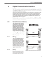
Serial Communications . . . . . . . . . . . . . . . . . . . . . . . 41
8.1.1
8.1.2
Wiring . . . . . . . . . . . . . . . . . . . . . . . . . . . . . . . . . . . . . . 41
Setup . . . . . . . . . . . . . . . . . . . . . . . . . . . . . . . . . . . . . . 41
8.1.2.1
8.1.2.2
8.1.2.3
8.1.2.4
8.1.3
8.1.4
.
.
.
.
.
.
.
.
.
.
.
.
.
.
.
.
.
.
.
.
.
.
.
.
.
.
.
.
.
.
.
.
.
.
.
.
.
.
.
.
.
.
.
.
.
.
.
.
.
.
.
.
.
.
.
.
.
.
.
.
.
.
.
.
.
.
.
.
.
.
.
.
.
.
.
.
.
.
.
.
.
.
.
.
.
.
.
.
.
.
.
.
.
.
.
.
.
.
.
.
.
.
.
.
.
.
.
.
.
.
.
.
.
.
.
.
.
.
.
.
.
.
.
.
.
.
.
.
.
.
.
.
.
.
.
.
.
.
.
.
.
.
.
.
. 42
. 42
. 42
. 42
Serial Operation . . . . . . . . . . . . . . . . . . . . . . . . . . . . . . . . . 43
IEEE-488 Communication . . . . . . . . . . . . . . . . . . . . . . . . . . . 43
8.1.4.1
8.1.4.2
8.2
8.3
Baud Rate . . .
Sample Period.
Duplex Mode .
Linefeed . . . .
Setup and Address Selection . . . . . . . . . . . . . . . . . . . . . . . . . . . . . . 43
IEEE-488 Operation . . . . . . . . . . . . . . . . . . . . . . . . . . . . . . . . . . 43
Interface Commands . . . . . . . . . . . . . . . . . . . . . . . . 43
Power Control Functions . . . . . . . . . . . . . . . . . . . . . . 44
8.3.1
8.3.2
Heater Control . . . . . . . . . . . . . . . . . . . . . . . . . . . . . . . . . 44
Cooling Control . . . . . . . . . . . . . . . . . . . . . . . . . . . . . . . . . 44
9 Calibration Procedure . . . . . . . . . . . . . . . . . . . . . . 49
9.1
RTD Probe Calibration . . . . . . . . . . . . . . . . . . . . . . . 49
9.1.1
9.1.2
9.1.3
9.1.4
Calibration Points . . . . . . .
Measuring the Set-point Error
Computing R and ALPHA . .
Calibration Example . . . . .
0
.
.
.
.
.
.
.
.
.
.
.
.
.
.
.
.
.
.
.
.
.
.
.
.
.
.
.
.
.
.
.
.
.
.
.
.
.
.
.
.
.
.
.
.
.
.
.
.
.
.
.
.
.
.
.
.
.
.
.
.
.
.
.
.
.
.
.
.
.
.
.
.
.
.
.
.
.
.
.
.
.
.
.
.
.
.
.
.
.
.
.
.
.
.
.
.
.
.
.
.
49
49
49
50
10 Maintenance . . . . . . . . . . . . . . . . . . . . . . . . . . . 53
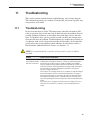
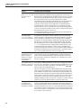
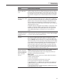
11 Troubleshooting. . . . . . . . . . . . . . . . . . . . . . . . . . 55
11.1
Troubleshooting . . . . . . . . . . . . . . . . . . . . . . . . . . . 55
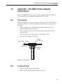
12 Appendix - 910 Bath Probe Adapter Instructions . . . . . . . 59
12.1
12.2
12.3
TC Cut-Out . . . . . . . . . . . . . . . . . . . . . . . . . . . . . 59
Control Probe . . . . . . . . . . . . . . . . . . . . . . . . . . . . 59
Attaching the Probe Adapter . . . . . . . . . . . . . . . . . . . . 60
12.4
Inserting the Probes . . . . . . . . . . . . . . . . . . . . . . . . . 60
iii
Figures and Tables
Table 1
Figure 1
Figure 2
Figure 3
Figure 4
Figure 5
Figure 6
Table 2
Figure 7
Figure 8
Table 3
Table 4
Table 5
Table 6
Figure 9
Figure 10
iv
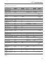
International Electrical Symbols . . . . . . . . . . . . . . . . . . . . . 1
Old heater configuration . . . . . . . . . . . . . . . . . . . . . . . . . 12
Present heater configuration . . . . . . . . . . . . . . . . . . . . . . . 12
Terminal Block . . . . . . . . . . . . . . . . . . . . . . . . . . . . . . 13
Front Control Panel . . . . . . . . . . . . . . . . . . . . . . . . . . . 17
Back Panel . . . . . . . . . . . . . . . . . . . . . . . . . . . . . . . . 18
Controller Flow Chart . . . . . . . . . . . . . . . . . . . . . . . . . . 24
Program mode setting actions . . . . . . . . . . . . . . . . . . . . . . 30
Temperature fluctuations at various proportional band settings . . . . . 32
Serial Communications Cable Wiring . . . . . . . . . . . . . . . . . . 41
Serial Interface Commands . . . . . . . . . . . . . . . . . . . . . . . 45
Serial Interface Commands continued . . . . . . . . . . . . . . . . . . 46
Serial Interface Commands continued . . . . . . . . . . . . . . . . . . 47
Power Control Functions. . . . . . . . . . . . . . . . . . . . . . . . . 48
Calibration Example — Platinum RTD Probe . . . . . . . . . . . . . . 51
Probe Adapter . . . . . . . . . . . . . . . . . . . . . . . . . . . . . . 59
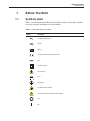
1 Before You Start
Symbols Used
1
1.1
Before You Start
Symbols Used
Table 1 lists the International Electrical Symbols. Some or all of these symbols
may be used on the instrument or in this manual.
Table 1 International Electrical Symbols
Symbol
Description
AC (Alternating Current)
AC-DC
Battery
Complies with European Union directives
DC
Double Insulated
Electric Shock
Fuse
PE Ground
Hot Surface (Burn Hazard)
Read the User’s Manual (Important Information)
Off
On
1
7900 Temperature Controller
User’s Guide
Symbol
Description
Canadian Standards Association
OVERVOLTAGE (Installation) CATEGORY II, Pollution Degree 2 per IEC1010-1 refers to the level of Impulse Withstand Voltage protection provided. Equipment of
OVERVOLTAGE CATEGORY II is energy-consuming equipment to be supplied from
the fixed installation. Examples include household, office, and laboratory appliances.
C-TIC Australian EMC mark
The European Waste Electrical and Electronic Equipment (WEEE) Directive
(2002/96/EC) mark.
1.2
Safety Information
Use this instrument only as specified in this manual. Otherwise, the protection
provided by the instrument may be impaired. Refer to the safety information in
Table 2.
The following definitions apply to the terms “Warning” and “Caution”.
• “WARNING” identifies conditions and actions that may pose hazards to
the user.
• “CAUTION” identifies conditions and actions that may damage the instrument being used.
1.2.1
WARNINGS
To avoid personal injury, follow these guidelines.
GENERAL
DO NOT use the instrument for any application other than calibration work.
The instrument was designed for temperature calibration. Any other use of the
instrument may cause unknown hazards to the user.
DO NOT use the instrument in environments other than those listed in the
user’s guide.
Follow all safety guidelines listed in the user’s manual.
Calibration Equipment should only be used by Trained Personnel.
If this instrument is used in a manner not specified by the manufacturer, the
protection provided by the instrument may be impaired.
If the instrument is used to control a calibration heat source, insure the heater is
wired correctly to the corresponding position on the internal strip as labeled.
The heater will heat continually if the heater and stirrer power are swapped (see
Figure 3 on page 13).
2
1 Before You Start
Safety Information
Before initial use, or after transport, or after storage in humid or semi-humid
environments, or anytime the dry-well has not been energized for more than 10
days, the instrument needs to be energized for a “dry-out” period of 2 hours before it can be assumed to meet all of the safety requirements of the
IEC-61010-1. If the product is wet or has been in a wet environment, take necessary measures to remove moisture prior to applying power such as storage in
a low humidity temperature chamber operating at 50°C for 4 hours or more.
The instrument is intended for indoor use only.
The instrument is a precision instrument. Although it has been designed for optimum durability and trouble free operation, it must be handled with care.
Operate the instrument in room temperatures listed in Section 3.2, Environmental Conditions.
The instrument is vented and clearance of 3 inches (7.62 cm) is recommended
above and around the sides the instrument.
DO NOT remove the feet attached to the bottom of the instrument. If the feet
are removed, contact an Authorized Service Center for replacements.
DO NOT place the instrument on top of a calibration bath or dry-well where it
would be in contact or direct path of heat.
DO NOT stack items on top of the instrument.
BURN HAZARD
The instrument can be used to control instruments which generate extreme temperatures. Precautions must be taken to prevent personal injury or damage to
objects. Probes may be extremely hot or cold when removed from a calibration
bath. Cautiously handle probes to prevent personal injury. Carefully place
probes on a heat resistant surface or rack until they are at room temperature.
Fires and severe burns may result if personnel fail to observe safety
precautions.
ELECTRICAL HAZARD
These guidelines must be followed to ensure that the safety mechanisms in this
instrument will operate properly. The instrument must be plugged into an appropriate outlet as specified in Section 2.1, Specifications, on page 7. Also, the
current and voltage capability of the instrument must not be exceeded. The
power cord of the instrument is equipped with a three-pronged grounding plug
for your protection against electrical shock hazards. It must be plugged directly
into a properly grounded three-prong receptacle. The receptacle must be installed in accordance with local codes and ordinances. Consult a qualified electrician. DO NOT use an extension cord or adapter plug.
DO use a ground fault interrupt device. This system that is controlled by this
instrument may contain a fluid. A ground fault device is advised in case fluid is
present in the electrical system and could cause an electrical shock.
3
7900 Temperature Controller
User’s Guide
Always replace the power cord with an approved cord of the correct rating and
type. If you have questions, contact a Authorized Service Center (see Section
1.3).
High voltage is used in the operation of this equipment. Severe injury or death
may result if personnel fail to observe the safety precautions. Before working
inside the instrument, turn off the power and disconnect the power cord.
FLUIDS
Fluids used in the system controlled by this instrument may produce noxious or
toxic fumes under certain circumstances. Consult the fluid manufacturer’s
MSDS (Material Safety Data Sheet). Proper ventilation and safety precautions
must be observed.
The instrument is equipped with a soft cutout (adjustable parameter) and a hard
cutout (set at the factory) Adjust the soft cutout according to fluid characteristics or application. As a guideline, the soft cutout should be set 10°C to 15°C
below the flash point of the fluid (see Section 7.10, Cutout). Insure that the
flash point, boiling point, or other key fluid characteristics are not exceeded.
1.2.2
CAUTIONS
To avoid possible damage to the instrument, folow these guidelines.
DO use a ground fault interrupt device.
Operate the instrument in room temperatures as listed in Section 3.2, Environmental Conditions.
Calibration constants should only be changed by trained personnel. The correct
setting of these parameters is important to the safety and proper operation of
the instrument.
The Factory Reset Sequence should be performed only by authorized personnel
if no other action is successful in correcting a malfunction. You must have a
copy of the most recent Report of Test to restore the test parameters.
The “cooling” outlet provided by the controller is for LN2 only. DO NOT connect mechanical cooling to the controller.
DO NOT operate this instrument in an excessively wet, oily, dusty, or dirty environment or place in locations where hot or cold liquids are splashed on it.
Most probes have handle temperature limits. Be sure that the probe handle temperature limit is not exceeded in the air above the system controlled by this
instrument.
The instrument and any thermometer probes used with it are sensitive instruments that can be easily damaged. Always handle these devices with care. Do
not allow them to be dropped, struck, stressed, or overheated.
DO NOT use this instrument in a system that exceeds the current capability of
the instrument as listed in Section 3.1, Specifications.
4
1 Before You Start
Authorized Service Centers
DO NOT replace fuse(s) with one of a higher current rating or type. Always replace the fuse with one of the same rating, voltage, and type. The current rating
listed in Section 3.1, Specifications, is the maximum for the instrument. If the
instrument is connected to a system which uses less than the maximum capability of this instrument, the fuses need to be changed in order to be correct for the
system. Once the instrument is connected to the system, the system current
needs to be measured or calculated and the appropriate fuse size and characteristics selected. Section 4.2.6, Fuses, can be used as a guide for selecting a fuse.
Once the correct fuse type and rating is selected, the following information is
applicable. The instrument is equipped with operator accessible fuses. If a fuse
blows, it may be due to a power surge or failure of a component. Replace the
fuses once. If a fuse blows a second time, it is likely caused by failure of a
component. As a test disconnect the output device (heater) and apply power to
the rest of the system. Check to see if the fuse(s) blow. If the fuse(s) blow only
when an output device (heater, stirrer, etc.) is connected, the fault may be in the
system component. If not, contact an Authorized Service Center (see Section
1.3).
If a mains supply power fluctuation occurs, immediately turn off the instrument. Power bumps from brown-outs and black-outs can damage the system.
Wait until the power has stabilized before re-energizing the instrument.
For best accuracy, the instrument needs to be calibrated with the system it
controls.
1.3
Authorized Service Centers
Please contact one of the following authorized Service Centers to coordinate
service on your Hart product:
Fluke Corporation, Hart Scientific Division
799 E. Utah Valley Drive
American Fork, UT 84003-9775
USA
Phone: +1.801.763.1600
Telefax: +1.801.763.1010
E-mail: [email protected]
Fluke Nederland B.V.
Customer Support Services
Science Park Eindhoven 5108
5692 EC Son
NETHERLANDS
5
7900 Temperature Controller
User’s Guide
Phone: +31-402-675300
Telefax: +31-402-675321
E-mail: [email protected]
Fluke Int'l Corporation
Service Center - Instrimpex
Room 2301 Sciteck Tower
22 Jianguomenwai Dajie
Chao Yang District
Beijing 100004, PRC
CHINA
Phone: +86-10-6-512-3436
Telefax: +86-10-6-512-3437
E-mail: [email protected]
Fluke South East Asia Pte Ltd.
Fluke ASEAN Regional Office
Service Center
60 Alexandra Terrace #03-16
The Comtech (Lobby D)
118502
SINGAPORE
Phone: +65 6799-5588
Telefax: +65 6799-5588
E-mail: [email protected]
When contacting these Service Centers for support, please have the following
information available:
• Model Number
• Serial Number
• Voltage
• Complete description of the problem
6
2 Introduction
2
Introduction
The Hart Scientific Model 7900 is a solid state temperature controller specifically designed to control the temperature of Rosemount designed temperature
calibration baths. The unique combination of analog and digital electronic circuitry provides exceptional accuracy and stability together with ease of operation and programmability.
Temperature sensing is done with a 4-wire 100-ohm platinum resistance probe
that plugs into the back of the controller. To maintain a constant temperature,
the controller adjusts the pulses of power supplied to the heater by means of a
solid state relay.
The 7900 controller can be easily programmed via the four-button front panel
or by the serial or IEEE interface. Programming allows the user to set the control temperature, temperature scale units to °C or °F, the proportional band, and
the calibration variables. The process or actual temperature is continuously displayed on a bright green LED panel. The percent heating power may also be
monitored.
An added safety device, the over-temperature cut-out, is also programmable.
This built-in feature protects the system from fault conditions causing excessive
temperature by disabling the heater if the temperature sensed by a separate
thermocouple probe exceeds the cut-out set-point. Before using the 7900 controller you should understand the proper setup and operation.
7
3 Specifications and Environmental Conditions
Specifications
3
3.1
3.2
Specifications and Environmental
Conditions
Specifications
Temperature Range
–100 °C to 400 °C (–148 °F to 752 °F)
Accuracy
± 1.0 °C
Stability
± 0.003 °C (depends on application)
Stabilization Time
approximately 30 minutes (depends on system design)
Control Probe
100Ω RTD, 4 wire
Resolution
0.0002 °C/°F in high-resolution mode
Readout
Switchable °C or °F
Cooling Control
LN2 – automatic (requires optional LN2 valve box)
Controller
Hybrid Digital/Analog controller with data retention
Interface
RS-232 and IEEE standard
Fault Protection
High temperature cutout (Type K thermocouple input)
Sensor burnout and short protection
Cutout Accuracy
± 10 °C
Combined Stir Motor
Heater and LN2
Cooling Outputs
(max)
115 VAC (±10%), 50/60 Hz, 15.8 A, 1815 W
Power (max)
115 VAC (±10%), 50/60 Hz, 16 A, 1840 W
Note: Internal electronics require 0.2 A to operate.
System Fuses
20 A 250 V slow blow (max)
Heater Fuses
20 A 250 V fast acting (max)
Exterior Dimension
72 mm H x 172 mm W x 250 mm D (2.83 in x 6.75 in x 9.86 in)
Weight
4.0 kg (9 lbs.)
Safety
OVERVOLTAGE (Installation) CATEGORY II, Pollution Degree 2 per
IEC-61010-1
Environmental Conditions
Although the instrument has been designed for optimum durability and trouble-free operation, it must be handled with care. The instrument should not be
operated in an excessively dusty or dirty environment. Maintenance and cleaning recommendations can be found in the Maintenance Section of this manual.
9
7900 Temperature Controller
User’s Guide
The instrument operates safely under the following conditions:
• ambient temperature range: 5 - 50°C (41 - 122ºF)
• ambient relative humidity: maximum 80% for temperature <31°C, decreasing linearly to 50% at 40°C
• pressure: 75kPa - 106kPa
• mains voltage within ± 10% of nominal
• vibrations in the calibration environment should be minimized
• altitude less than 2,000 meters
• indoor use only
10
4 Quick Start
Unpacking
4
Quick Start
This section provides a brief summary of the steps required to set up and operate the 7900 temperature controller. This section should be used as a general
overview and reference not as a substitute for the remainder of the manual.
Please read Sections 4.2 though 6 carefully before operating the controller.
4.1
Unpacking
Unpack the controller carefully and inspect it for any damage that may have occurred during shipment. If there is shipping damage, notify the carrier
immediately.
An RTD control probe and a thermocouple cut-out probe should have been purchased along with the controller.
Verify that the following components are present:
• 7900 Controller with attached power cord
• Control Probe
• Thermocouple Probe
• User’s Guide
• Probe Adapter (2)
• Extra power cord (15 Amp)
4.2
4.2.1
Installation
Setup
The 7900 controller is a precision instrument that should be located in an appropriate environment. The location should be free from excessive dirt, moisture, vibration, or temperature variations. There should be no present danger of
spilled liquids.
4.2.2
Heater/Stirrer/LN2 Cooling
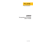
In order to access the terminal block connectors (Figure 3) for the heater, stirrer
motor, and LN2 Cooling, remove the top cover of the controller.
4.2.2.1
Heater Connection
CAUTION: READ THIS ENTIRE PROCEDURE BEFORE CONNECTING THE HEATERS!
11
7900 Temperature Controller
User’s Guide
This controller can be used with the following heater assemblies. If the heater
assembly that you are using is not listed, please call Hart Scientific Customer
Service for assistance.
Part number
Power
Resistance
00910-0125-0001
260/440 W
50/30 Ohms
00910-0126-0001
825/825 W
16/16 Ohms
00910-0126-0002
825/825 W
16/16 Ohms
00913-0072-0001
500/500 W
28/28 Ohms
To connect the heater perform the following steps after removing the top cover
of the controller (four screws). Be sure the heater cable is adequate for the
amount of current required and that the heater is wired correctly and safely.
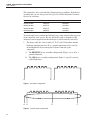
1.
The heater cable has 4 wires labeled C, D, E, and G. Determine whether
the heater configuration uses G as a ground connection or G as one leg
of the High heater by measuring the resistance from the spade
connectors.
a)
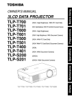
The PRESENT heater assembly configuration (Figure 2) uses G as a
ground connection
b) The OLD heater assembly configuration (Figure 1) uses G as one leg
of the High heater.
G
D
C
E
Figure 1 Old heater configuration
G D
Figure 2 Present heater configuration
12
E
C
4 Quick Start
Installation
4.2.2.2
2.
Feed the wires through the strain relief labeled “HEATER” and route
them to the terminal block.
3.
If you have the PRESENT heater assembly configuration (Figure 2),
connect all the wires as labeled on the terminal block.
4.
If you have the OLD heater assembly configuration (Figure 1), connect
the D and G wires together into the terminal slot labeled D. Connect the
rest of the wires as labeled. There is no direct ground connection through
the heater wires. Instead the assembly will be grounded through the flow
chute assembly.
5.
The heater hookup is complete.
Stir Motor Connection
Connect the stirring device to the back of the controller through the strain relief
labeled “STIR MOTOR”. Secure the stirrer to the terminal block at the terminals marked A, B, and G for the stirrer. See Figure 3.
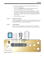
4.2.2.3
LN2 Connection
Connect the LN2 cooling through the strain relief labeled “COOLING DEVICE”. Secure the LN2 cooling to the terminal block at the terminals marked
Heater
LN2 Cooling
Stir Motor
H
I
G
H
L
O
W
LORTNOC
EBORP
RETAEH
XAM STTAW 0091
T
CT
EBORP
R
S
A
B
G
G
D
E
C
GNILOOC
ECIVED
RITS
ROTOM
232- SR
884- EEEI
~
zH 06
CAV 511
XAM PMA 02
LANRETNI ESUF
Figure 3 Terminal Block
13
7900 Temperature Controller
User’s Guide
R, S, and T for cooling. DO NOT attach mechanical cooling through the
controller.
CAUTION: Be sure that the combined current of the heater, stirrer, and
LN2 cooling does not exceed 20 amps.
4.2.3
Control Probe
Connect the control probe into the socket at the back of the controller labeled
“CONTROL PROBE” (see Figure 5). Insert the probe into the bath or system to
be controlled. For best stability and response time the control probe should be
located in close proximity to the heater. Observe the maximum temperature rating of the probe and be careful it is not exceeded.
4.2.4
Thermocouple Probe
Connect the thermocouple cut-out probe to the back of the controller to the
connector labeled “TC PROBE”. Insert the probe into the bath or system being
controlled.
4.2.5
Power
Connect the controller power cord to a power source of the appropriate voltage
and current rating (see Section 3.1, Specifications).
4.2.6
Fuses
CAUTION: Never use this instrument in a system that uses more power or
current as listed in Section 3.1, Specifications.
The controller is shipped from the factory with fast acting fuses rated for the
maximum capacity of the instrument.
If the controller is connected to a system which uses less than 10 amps, the
fuses will need to be changed in order to be correct for the system. Once the
controller is connected in the system, the system current needs to be measured
or calculated and the appropriate fuse size and characteristics selected. Generally, the fuse selected is rated at 125% of the maximum current of the system.
The time-current characteristics of the fuse are selected by the application.
Usually, fast acting fuses are selected systems without a high in-rush current,
i.e. "hot" calibration baths. Time-delay or slow blow fuses are selected for systems with a high in-rush current, i.e. "cold" calibration baths. Refer to the
fuseology section of your fuse catalog for help in determining fuse size and
characteristics or contact an Authorized Service Center (see Section 1.3) for assistance. Once the correct fuse characteristics and rating of the fuses have been
selected and the appropriate fuses placed in the power entry module of the instrument, mark the instrument so the user can visibly see the fuse size and rat-
14
4 Quick Start
Setting the Temperature
ing for fuse replacement. Be sure to change both fuses to the new rating and
correct characteristic.
The controller uses 0.2 amps of current. This current should be taken into consideration when calculating the system power.
Example when using the power of the system:
P = Power of the system (Total Watts)
V = Nominal line voltage (115 VAC)
I = Fuse current
I = 1.25 ×
P
0.9 × v
Example when using the system current:
I = System current
IF = Fuse current rating
I F = 1.25 × I
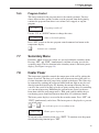
4.2.7
Power Cord
Once the correct fuse is selected, the proper power cord can be selected. The
controller is shipped with a 20 Amp 125 VAC power cord to accommodate the
maximum power rating. An extra power cord rated for 15 Amps 125 VAC is included. If the total system current is 12 Amps or less, the 20 Amp power cord
may be replaced with the 15 Amp power cord. If the system current exceeds12
amps using the 15 amp power cord, the recommendations of the National Electric Code (NEC) are exceeded. You must use the 20 amp power cord once the
system current exceeds 12 amps.
WARNING: DO NOT USE THE 15 AMP POWER CORD UNDER ANY
CIRCUMSTANCES IF THE SYSTEM CURRENT EXCEEDS 12 AMPS.
4.3
Setting the Temperature
In the following discussion and throughout this manual a solid box around the
word SET, UP, DOWN or EXIT indicates the panel button to press while the
dotted box indicates the display reading on the front panel. Explanation of the
button function or display reading is written at the right.
To view or set the temperature set-point proceed as follows. The front panel
LED display normally shows the actual process temperature.
Section 7.3 explains in detail how to set the temperature set-point on the controller using the front panel keys. The procedure is summarized here.
(1) Press “SET” twice to access the set-point value.
15
7900 Temperature Controller
User’s Guide
(2) Press “UP” or “DOWN” to change the set-point value.
(3) Press “SET” to accept the new set-point and to display the vernier value.
(4) Press “EXIT” to return to the temperature display.
When the set-point temperature is changed the system heats or cools until the
new set-point is reached. The over-temperature cut-out should be correctly set
for added safety. See Section 7.10
To obtain optimum control stability adjust the proportional band as discussed in
Section 7.9.
16
5 Parts and Controls
Front Panel
5
5.1
Parts and Controls
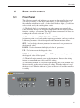
Front Panel
The following controls and indicators are present on the controller front panel
(see Figure 4 below): (1) the digital LED display, (2) the control buttons, (3)
the controller on/off power switch, (4) the control indicator light, (5) the heater
select switch, and (6) the cooling power switch.
(1) The digital display is an important part of the temperature controller because it not only displays set and actual temperatures but also displays various
functions, settings, and constants. The display shows temperatures in values according to the selected scale units °C or °F.
(2) The control buttons (SET, DOWN, UP, and EXIT) are used to set the temperature set-point, access and set other operating parameters, and access and set
calibration parameters. A brief description of the button functions follows:
SET – Used to display the next parameter in a menu and to set parameters to
the displayed value.
DOWN – Used to decrement the displayed value of parameters.
UP – Used to increment the displayed value.
EXIT – Used to exit from a menu. When EXIT is pressed any changes made to
the displayed value will be ignored.
(3) The on/off switch controls power to the instrument. It powers the stirring
motor, the controller/heater circuit, and LN2 cooling.
(4) The control indicator is a two color light emitting diode. This indicator lets
the user visually see the ratio of heating to cooling. When the indicator is red
the heater is on. When the indicator is green the heater is off and the controller
is cooling.
Figure 4 Front Control Panel
17
7900 Temperature Controller
User’s Guide
(5) The heater power is either automatic or user selected. The heater power
switch is used to select the appropriate heater power levels for heating and controlling at various temperatures. Selecting “HIGH” heat manually overrides the
automatic system.
(6) The cooling power switch controls power to the LN2 cooling. Once the LN2
cooling is energized, the flow is automatically controlled.
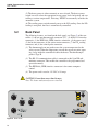
5.2
Back Panel
The following features are found on the back panel (see Figure 5) of the controller: (1) the cut-out thermocouple connector (TC), (2) the RS-232 interface
connector, (3) the IEEE-488 (GPIB) interface connector, (4) the power cord,
(5) the heater connector, (6) the stirrer motor connector, (7) the LN2 cooling
connector, and (8) the control probe connector.
(1) The thermocouple cut-out probe senses the system temperature for the
safety cut-out. When the temperature exceeds the cut-out set-point, opening a relay inside the controller disables the heater. The thermocouple
probe is Type K.
(2) The RS-232 communications cable is connected to this 9 pin DB subminiature connector. This enables the controller to be programmed and
operated remotely.
(3) The IEEE-488 (GPIB) interface connector is for remote computer
control.
(4) The power cord is rated at 115 VAC at 20 amps.
CAUTION: Do not draw more than 20 amps.
Note: The heater and system fuses are internal.
Figure 5 Back Panel
18
5 Parts and Controls
Back Panel
(5) The heater connector is the source of controlled power for the system
heater. This power is switched by the solid-state relay to maintain a constant temperature. To connect the heater, remove the top cover of the
controller. The heater cable is fed through the strain relief in the back
panel and the spade connectors are attached to the appropriate terminals
on the internal terminal block. See Figure 3. The heater control for temperature range is automatic. The automatic system can be manually overridden by turning the heater power to high using the front panel switch.
(6) The stirrer motor connector is an auxiliary power socket for the stirrer
motor. This power is constant. The combined current of the heater, stirrer
motor, and LN2 cooling must not exceed 20 amps. The stirrer motor cable is fed through the strain relief in the back panel and the spade connectors are attached to the appropriate terminals on the terminal block
inside the controller. See Figure 3.
(7) The LN2 cooling device connector is the source of controlled power for
the system LN2 cooling.
CAUTION: The cooling power is for LN2 cooling only. Do not use this
connection for mechanical cooling.
This power is switched by the solid-state relay. The LN2 cooling alternates with the heater power to maintain a constant temperature. The LN2
cooling cable is fed through the strain relief in the back panel and the
spade connectors are attached to the appropriate terminals on the internal
terminal block. See Figure 3.
(8) The control probe connector for the system, attaches the 100Ω control
RTD.
19
6 General Operation
Control System
6
6.1
General Operation
Control System
The 7900 temperature controller is specified for use with the Rosemount designed calibration baths. The controller’s flexibility enables it to be used with
all Rosemount designed calibration bath systems.
It is the responsibility of the user to ensure that the components are chosen and
the system constructed to ensure safe and proper operation of the complete system. The user should have a good knowledge of and experience with electrical
fundamentals and wiring practices as well as control systems. Hart Scientific
cannot be responsible for any damages or injuries resulting from improper design or operation of the control system. Technical support for setting up and
operating a control system using the 7900 controller is available by telephone
or fax from Hart Scientific. Be sure to read this 7900 user manual completely.
6.2
Power
Power to the controller is provided by an AC mains supply as specified in Section 3.1, Specifications. Power to the controller passes through an internal filter
to prevent switching spikes from being transmitted to other equipment.
To turn on the controller switch the control panel power switch to the ON position. The LED display will begin to show the process temperature and the
heater will turn on or off until the bath temperature reaches the programmed
set-point.
When powered on the control panel display will briefly show a four digit number. This number indicates the number of times power has been applied to the
controller. Also briefly displayed is data that indicates the controller hardware
configuration. This data is used in some circumstances for diagnostic purposes.
6.3
Heater
The power to the heater plugged into the controller is precisely controlled to
maintain a constant system temperature. Power is controlled by periodically
switching the heater on for a certain amount of time using a solid-state relay.
The front panel red/green control indicator shows the state of the heater. The
control indicator glows red when the heater is on and glows green when the
heater is off. The indicator will pulse constantly when the controller is maintaining a stable temperature.
The heater power automatically switches between low and high when the bath
is being heated to a new temperature. The automatic system can be overridden
by turning the heater switch to “HIGH” power.
21
7900 Temperature Controller
User’s Guide
6.4
LN2 Cooling
The power to the LN2 cooling device plugged into the back of the controller is
precisely controlled. Power is controlled by periodically switching the cooling
on for a certain amount of time using a solid-state relay. The LN2 cooling alternates with the heater power to maintain a constant temperature.
6.5
Temperature Controller
Hart Scientific’s unique hybrid digital/analog temperature controller manipulates the system temperature. The controller offers the precise stability of an analog temperature controller as well as the flexibility and programmability of a
digital controller.
The temperature is monitored with a platinum resistance sensor in the control
probe. The signal is electronically compared with the programmable reference
signal, amplified, and then passed to a pulse-width modulator circuit which
controls the amount of power applied to the bath heater.
As a secondary protection device, the controller is also equipped with a separate thermocouple temperature monitoring circuit that shuts off the heater if the
temperature exceeds the cut-out set-point.
The controller allows the operator to set the set-point temperature with high
resolution, set the cut-out, adjust the proportional band, monitor the heater output power, and program the controller configuration and calibration parameters.
The controller may be operated in temperature units of degrees Celsius or Fahrenheit. The controller is operated and programmed from the front control panel
using the four key switches and digital LED display. The controller is equipped
with an RS-232 serial and an IEEE-488 (GPIB) digital interface for remote operation. Operation of the controller using the front control panel is discussed in
Section 8. Operation using the digital interface is discussed in Section 9.
When the controller is set to a new set-point the system heats or cools to the
new temperature. Once the new temperature is reached it usually takes 10-15
minutes for the temperature to settle and stabilize. There may be a small overshoot or undershoot of about 0.5°C or more depending on the system and proportional band.
22
7 Controller Operation
Process Temperature
7
Controller Operation
This section discusses in detail how to operate the temperature controller using
the front control panel. Using the front panel key switches and LED display the
user may monitor the process temperature, set the temperature set-point in degrees C or F, monitor the heater output power, adjust the controller proportional
band, set the cut-out set-point, and program the probe calibration parameters,
operating parameters, serial and IEEE-488 interface configuration, and controller calibration parameters. Operations of the functions are shown in the
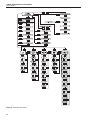
flowchart summarized in Figure 6.
7.1
Process Temperature
The digital LED display on the front panel allows direct viewing of the process
temperature. This temperature value is what is normally shown on the display.
The units, C or F, of the temperature value are displayed at the right. For
example,
25.00 C
Process temperature in degrees Celsius
The temperature display function may be accessed from any other function by
pressing the “EXIT” button.
7.2
Reset Cut-out
If the over-temperature cut-out has been triggered then the temperature display
will alternately flash,
cut-out
Indicates cut-out condition
The message will continue to flash until the temperature is reduced and the
cut-out is reset. The cut-out has two modes, automatic reset and manual reset,
and determines how the cut-out is reset. In automatic mode, the cut-out resets
itself as soon as the temperature is lowered below the cut-out set-point. In manual reset mode, the operator must reset the cut-out after the temperature falls
below the set-point. When the cut-out is active and the cut-out mode is set to
manual (“reset”), the display flashes “cut-out” until the user resets the
cut-out. To access the reset cut-out function press the “SET” button.
S
Access cut-out reset function
The display indicates the reset function.
rESEt ?
Cut-out reset function
Press “SET” once more to reset the cut-out.
23
7900 Temperature Controller
User’s Guide
Figure 6 Controller Flow Chart
24
7 Controller Operation
Temperature Set-point
S
Reset cut-out
This action also switches the display to the set temperature function. To return
to displaying the temperature, press the “EXIT” button. If the cut-out is still in
the over-temperature fault condition the display will continue to flash
“cut-out”. The bath temperature must drop a few degrees below the cut-out
set-point before the cut-out can be reset.
7.3
Temperature Set-point
The temperature can be set to any value within the range given in the specifications. The operator must know the temperature range of the particular fluid
used in the bath. The bath should only be operated well below the upper temperature limit of the liquid or device inserted into the liquid. In addition, the
cut-out temperature should also be set below the upper limit of the fluid.
Setting the temperature involves three steps: (1) select the set-point memory,
(2) adjust the set-point value, and (3) adjust the vernier, if desired.
7.3.1
Programmable Set-points
The controller stores 8 set-point temperatures in memory. The set-points can be
quickly recalled to conveniently set the system to a previously programmed
temperature. To set the temperature one must first select the set-point memory.
This function is accessed from the temperature display function by pressing
“SET”. The number of the set-point memory currently being used is shown at
the left on the display followed by the current set-point value.
25.00 C
S
Process temperature in degrees Celsius
Access set-point memory
1. 25.0
Set-point memory 1, 25.0°C currently used
To change the set-point memory press “UP” or “DOWN”.
U
Increment memory
4. 40.0
New set-point memory 4, 40.0°C
Press “SET” to accept the new selection and access the set-point value.
S
7.3.2
Accept selected set-point memory
Set-point Value
The set-point value may be adjusted after selecting the set-point memory and
25
7900 Temperature Controller
User’s Guide
pressing “SET”. The set-point value is displayed with the units, C or F, at the
left.
C 40.00
Set-point 4 value in °C
If the set-point value does not need to be changed then press “EXIT” to resume
displaying the temperature. To adjust the set-point value press “UP” or
“DOWN”.
U
Increment display
C 42.50
New set-point value
When the desired set-point value is reached press “SET” to accept the new
value and access the set-point vernier. If “EXIT” is pressed any changes made
to the set-point are ignored.
S
7.3.3
Accept new set-point value
Set-point Vernier
The set-point value can be set with a resolution of 0.01°C. The user may want
to adjust the set-point slightly to achieve a more precise temperature. The
set-point vernier allows one to adjust the temperature below or above the
set-point by a small amount with very high resolution. Each of the 8 stored
set-points has an associated vernier setting. The vernier is accessed from the
set-point by pressing “SET”. The vernier setting is displayed as a 6 digit number with five digits after the decimal point. This is a temperature offset in degrees of the selected units, C or F.
0.00000
Current vernier value in °C
To adjust the vernier press “UP” or “DOWN”. Unlike most functions the vernier setting has immediate effect as it is adjusted allowing the user to continually adjust the system temperature with the vernier as the temperature is
displayed. “SET” does not need to be pressed.
U
Increment display
0.00090
New vernier setting
Next press “EXIT” to return to the temperature display or “SET” to access the
temperature scale units selection.
S
26
Access scale units
7 Controller Operation
Temperature Scale Unit
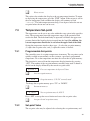
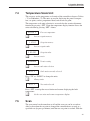
7.4
Temperature Scale Unit
The user may set the temperature scale units of the controller to degrees Celsius
(°C) or Fahrenheit (°F). The units are used in displaying the process temperature, set-point, vernier, proportional band, and cut-out set-point.
The temperature scale units selection is accessed after the vernier adjustment
function by pressing “SET”. From the temperature display function access the
units selection by pressing “SET” 4 times.
25.00 C
S
Access set-point memory
1. 25.0
S
Set-point value
Access vernier
0.00000
S
Set-point memory
Access set-point value
C 25.00
S
Process temperature
Vernier setting
Access scale units selection
Un= C
Scale units currently selected
Press “UP” or “DOWN” to change the units.
U
Change units
Un= F
New units selected
Press “SET” to accept the new selection and resume displaying the bath
temperature.
S
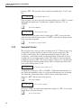
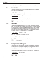
7.5
Set the new units and resume temperature display
Scan
The scan control can be turned on or off and the scan rate can be set and enabled so that when the set-point is changed the controller heats or cools at a
specified rate (degrees per minute) until the new set-point is reached. With the
27
7900 Temperature Controller
User’s Guide
scan disabled the controller heats or cools at the maximum possible rate.
7.5.1
Scan Control
The scan is controlled with the scan on/off function that appears in the main
menu after the set-point function.
ScAn=OFF
Scan function off
Press “UP” or “DOWN” to toggle the scan on or off.
ScAn=On
Scan function on
Press “SET” to accept the present setting and continue.
S
7.5.2
Accept scan setting
Scan Rate
The next function in the main menu is the scan rate. The scan rate can be set
from .1 to 100 °C/min. The maximum scan rate, however, is actually limited by
the natural heating or cooling rate of the instrument which is often less than
100 °C/min, especially when cooling. The scan rate function appears in the
main menu after the scan control function. The scan rate units are in degrees
per minute, degrees C or F depending on the selected units.
Sr= 10.0
Scan rate in °C/min
Press “UP” or “DOWN” to change the scan rate.
Sr= 2.0
New scan rate
Press “SET” to accept the new scan rate and continue.
S
7.6
Accept scan rate
Ramp and Soak Program
The ramp and soak program feature allows the user to program a number of
set-points and have the controller automatically cycle between the temperatures, holding at each for a determined length of time. The user can select one
of four different cycle functions.
The program parameter menu is accessed by pressing “SET” and then “UP”.
28
100.00 C
Well temperature
S+U
Access program menu
7 Controller Operation
Ramp and Soak Program
ProG
Program menu
Press “SET” to enter the program menu
S
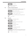
7.6.1
Enter program menu
Number of Program Set-points
The first parameter in the program menu is the number of set-points to cycle
through. Up to 8 set-points can be used in a ramp and soak program.
Pn=8
Number of program set-points
Use the “UP” or “DOWN” buttons to change the number from 2 to 8.
Pn=3
New number of program set-points
Press “SET” to continue. Press “EXIT” to ignore any changes made to the
parameter.
S
7.6.2
Save new setting
Set-points
The next parameters are the program set-points.
1 50.0
First set-point
Use the “UP” or “DOWN” buttons to select any of the set-points.
3 150.0
Third set-point
Press “SET” to be able to change the set-point.
C 150.00
Set-point value
Use “UP” and “DOWN” to change the set-point value.
C 165.00
New set-point value
Press “SET” to save the new set-point value. The other set-points can also be
set in the same manner. Once the set-points are programmed as desired press
“EXIT” to continue.
E
Continue to next menu function
29
7900 Temperature Controller
User’s Guide
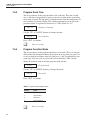
7.6.3
Program Soak Time
The next parameter in the program menu is the soak time. This time, in minutes, is the time each program set-points waits after settling before proceeding
to the next set-point. The duration is counted from the time the temperature settles to within a specified stability. The stability requirement can be set in the
parameter menu as explained in Section 6.13.4. The default is 0.1°C.
Soak time in minutes
Pt=15
Use the “UP” or “DOWN” buttons to change the time.
New soak time
Pt=5
Press “SET” to continue.
S
7.6.4
Save new setting
Program Function Mode
The next parameter is the program function or cycle mode. There are four possible modes that determine whether the program scans up (from set-point 1 to
n) only or both up and down (from set-point n to 1), and also whether the program stops after one cycle or repeats the cycle indefinitely. Table 3 below
shows the action of each of the four program mode settings.
Program mode
Pf=1
Use the “UP” or “DOWN” buttons to change the mode.
New mode
Pf=4
Press “SET” to continue.
Table 2 Program mode setting actions
Function
Action
1
Up-Stop
2
Up-Down-Stop
3
Up-Repeat
4
Up-Down-Repeat
S
30
Save new setting
7 Controller Operation
Secondary Menu
7.6.5
Program Control
The final parameter in the program menu is the control parameter. You may
choose between three options to either start the program from the beginning,
continue the program from where it was when it was stopped, or stop the
program.
Pr=OFF
Program presently off
Use the “UP” or “DOWN” buttons to change the status.
Pr=StArt
Start cycle from beginning
Press “SET” to activate the new program control command and return to the
temperature display.
S
7.7
Activate new command.
Secondary Menu
Functions, which are used less often, are accessed within the secondary menu.
Pressing “SET” and “EXIT” simultaneously and then releasing accesses the
secondary menu. The first function in the secondary menu is the heater power
display. (See Figure 6 on page 24.)
7.8
Heater Power
The temperature controller controls the temperature of the well by pulsing the
heater on and off. The duty cycle or the ratio of heater on time to the pulse cycle time determines the total power being applied to the heater. This value may
be estimated by watching the red/green control indicator light or may be read
directly from the digital display. By knowing the amount of heating the user
can tell if the system is heating up to the set-point, cooling down, or controlling
at a constant temperature. Monitoring the percent heater power lets the user
know how stable the well temperature is. With good control stability the percent heating power should not fluctuate more than ±5% within one minute.
The heater power display is accessed in the secondary menu. Press “SET” and
”EXIT” simultaneously and release. The heater power is displayed as a percentage of full power.
S+E
100 Pct
Access heater power in secondary menu
Heater power in percent
To exit out of the secondary menu press “EXIT”. To continue on to the proportional band setting function press “SET”.
31
7900 Temperature Controller
User’s Guide
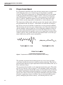
7.9
Proportional Band
In a proportional controller such as this the heater output power is proportional
to the well temperature over a limited range of temperatures around the
set-point. This range of temperature is called proportional band. At the bottom
of the proportional band the heater output is 100%. At the top of the proportional band the heater output is 0%. Thus as the temperature rises the heater
power is reduced, which consequently tends to lower the temperature back
down. In this way the temperature is maintained at a fairly constant value.
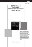
The temperature stability of the well and response time depend on the width of
the proportional band. See Figure 7. If the band is too wide the well temperature deviates excessively from the set-point due to varying external conditions.
This deviation is because the power output changes very little with temperature
and the controller cannot respond very well to changing conditions or noise in
the system. If the proportional band is too narrow the temperature may swing
back and forth because the controller overreacts to temperature variations. Best
stability control is only possible when the proportional band is set for the optimum width for the specific system configuration.
Figure 7 Temperature fluctuations at various proportional band settings
The optimum proportional band width depends on several factors including
system heat transfer characteristics and heater-probe positioning. Thus the proportional band width may require adjustment for best bath stability when any of
these conditions change.
The proportional band width is easily adjusted from the front panel. The width
may be set to discrete values in degrees C or F depending on the selected units.
The optimum proportional bandwidth setting may be determined by monitoring
the stability with a high resolution thermometer or with the controller percent
output power display. Narrow the proportional bandwidth to the point at which
the process temperature begins to oscillate. Increase the bandwidth from this
point by multiplying the current value by 3 and entering this new value.
32
7 Controller Operation
Cutout
The integral time of the controller is determined by component selection and
cannot be set by the user. This value is fixed at approximately 300 seconds.
The proportional band adjustment can be accessed within the secondary menu.
Press “SET” and “EXIT” to enter the secondary menu and show the heater
power. Then press “SET” twice to access the proportional band.
S+E
100 Pct
S
Access heater power in secondary menu
Heater power in percent
Access set-point voltage
Pb=0.101C
Proportional band setting
To change the proportional band press “UP” and “DOWN”.
D
Decrement display
Pb=0.060C
New proportional band setting
To store the new setting and access the cut-out set-point press “SET”. Press
“EXIT” to exit out of the secondary menu.
S
7.10
Accept the new proportional band setting
Cutout
As a protection against software or hardware fault, shorted heater triac, or user
error, the controller is equipped with an adjustable heater cutout device that
shuts power off to the heater if the system temperature exceeds a set value. This
protects the heater and system materials from excessive temperatures. The cutout temperature is programmable by the operator from the front panel of the
controller. The cutout temperature must always be set below the upper temperature limit of the bath fluid.
If the cutout is activated because of excessive temperature, power to the heater
shuts off and the system cools. The system cools until it reaches a few degrees
below the cutout set-point temperature. At this point the action of the cutout is
determined by the setting of the cutout mode parameter. The cutout has two
modes — automatic reset or manual reset. If the mode is set to automatic, the
cutout automatically resets when the system temperature falls below the reset
temperature allowing the system to heat up again. If the mode is set to manual,
the heater remains disabled until the user manually resets the cutout.
The cutout set-point may be accessed within the secondary menu. Press “SET”
and “EXIT” to enter the secondary menu and show the heater power. Then
press “SET” twice to access the cutout set-point.
33
7900 Temperature Controller
User’s Guide
S+E
12 Pct
S
Heater power in percent
Access proportional band
Pb= 0.101C
S
Access heater power in secondary menu
Proportional band setting
Access cutout set-point
CO= 210C
Cutout set-point
To change the cutout set-point press “UP” or “DOWN”.
D
Decrement display
CO= 95C
New cutout set-point
To accept the new cutout set-point press “SET”.
S
Accept cutout set-point
The next function is the configuration menu. Press “EXIT” to resume displaying the temperature.
7.11
Controller Configuration
The controller has a number of configuration and operating options and calibration parameters that are programmable via the front panel. These are accessed
from the secondary menu after the proportional band function by pressing
“SET”. The display prompts with “ConFIG”. Press “SET” again to enter the
first of five groups of configuration parameters—probe parameters, operating
parameters, serial interface parameters, IEEE parameters, and calibration parameters. The groups are selected using the “UP” and “DOWN” keys and then
pressing “SET”. (See Figure 6 on page 24)
7.12
Probe Parameters RTD Sensor
The probe parameter menu is indicated by,
PrObE
Probe parameters menu
Press “SET” to enter the menu. The probe parameters menu contains the parameters, R0 and ALPHA, which characterize the resistance-temperature relationship of the platinum control probe. These parameters may be adjusted to
34
7 Controller Operation
Operating Parameters
improve the accuracy of the bath. This procedure is explained in detail in Section 9.
The probe parameters are accessed by pressing “SET” after the name of the parameter is displayed. The value of the parameter may be changed using the
“UP” and “DOWN” buttons. After the desired value is reached press “SET” to
set the parameter to the new value. Pressing “EXIT” causes the parameter to be
skipped ignoring any changes that may have been made.
7.12.1
R0
This probe parameter refers to the resistance of the control probe at 0°C. Normally this is set for 100.000 ohms.
7.12.2
ALPHA
This probe parameter refers to the average sensitivity of the probe between 0
and 100°C. Normally this is set for 0.00385°C.
7.13
Operating Parameters
The operating parameters menu is indicated by,
PAr
Operating parameters menu
Press “SET” to enter the menu. The operating parameters menu contains the
cutout reset mode and soak stability.
7.13.1
Cutout Reset Mode
The cutout reset mode determines whether the cutout resets automatically when
the system temperature drops to a safe value or must be manually reset by the
operator.
The parameter is indicated by,
CtorSt
Cutout reset mode parameter
Press “SET” to access the parameter setting. Normally the cutout is set for
manual mode.
Cto=rSt
Cutout set for manual reset
To change to automatic reset mode press “UP” and then “SET”.
Cto=Auto
Cutout set for automatic reset
35
7900 Temperature Controller
User’s Guide
7.13.2
Soak Stability
The soak stability controls the required stability of the well temperature. The
stability is in degrees Celsius. The default is 0.1°C.
This parameter is indicated by,
StAb
Soak stability parameter
Press “SET” to access the parameter setting.
0.50
Soak stability set for 0.50°C
To change the parameter setting, press “UP” or “DOWN” and then “SET” to
store the value.
7.13.3
Boost Temperature Offset
The boost temperature offset allows the user to select the boost value (Δt) at
which the boost heat turns off. The boost heat switches off if the temperature is
within the boost value (Δt) of the set-point. The boost heat switches on if the
temperature falls below the set-point by the boost value of plus 0.1°C. The
boost value is always in degrees C even if the unit is set to degrees F.
This parameter is indicated by,
bOOSt
Boost temperature offset
Press "SET" to access the parameter setting.
bO= 4.0
Boost temperature offset set for 4.0°C
To change the parameter setting, press "UP" or "DOWN" and then "SET" to
store the value.
7.14
Serial Interface Parameters
The serial RS-232 interface parameters menu is indicated by,
SEriAL
Serial RS-232 interface parameters menu
The serial interface parameters menu contains parameters which determine the
operation of the serial interface. The parameters in the menu are: baud rate,
sample period, duplex mode, and linefeed.
7.14.1
Baud Rate
The baud rate is the first parameter in the menu. The baud rate setting determines the serial communications transmission rate.
36
7 Controller Operation
Serial Interface Parameters
The baud rate parameter is indicated by,
bAUd
Serial baud rate parameter
Press “SET” to choose to set the baud rate. The current baud rate value is then
displayed.
2400
Current baud rate
The baud rate of the serial communications may be programmed to 300 600,
1200, or 2400 baud. 2400 baud is the default setting. Use “UP” or “DOWN” to
change the baud rate value.
4800 b
New baud rate
Press “SET” to set the baud rate to the new value or “EXIT” to abort the operation and skip to the next parameter in the menu.
7.14.2
Sample Period
The sample period is the next parameter in the serial interface parameter menu.
The sample period is the time period in seconds between temperature measurements transmitted from the serial interface. If the sample rate is set to 5, the instrument transmits the current measurement over the serial interface
approximately every five seconds. The automatic sampling is disabled with a
sample period of 0. The sample period is indicated by,
SAMPLE
Serial sample period parameter
Press “SET” to choose the sample period. The current sample period value is
displayed.
SA=1
Current sample period (seconds)
Adjust the value with “UP” or “DOWN” and then use “SET” to set the sample
rate to the displayed value. “EXIT” does not store the new value.
SA=60
7.14.3
New sample period
Duplex Mode
The next parameter is the duplex mode. The duplex mode may be set to full duplex or half duplex. With full duplex any commands received by the controller
via the serial interface are immediately echoed or transmitted back to the device
of origin. With half duplex the commands are executed but not echoed. The duplex mode parameter is indicated by,
37
7900 Temperature Controller
User’s Guide
dUPL
Serial duplex mode parameter
Press “SET” to access the mode setting.
dUP=FULL
Current duplex mode setting
The mode may be changed using “UP” or DOWN” and pressing “SET”.
dUP=HALF
7.14.4
New duplex mode setting
Linefeed
The final parameter in the serial interface menu is the linefeed mode. This parameter enables (on) or disables (off) transmission of a linefeed character (LF,
ASCII 10) after transmission of any carriage-return. The linefeed parameter is
indicated by,
LF
Serial linefeed parameter
Press “SET” to access the linefeed parameter.
LF=On
Current linefeed setting
The mode may be changed using “UP” or “DOWN” and pressing “SET”.
LF=OFF
7.15
New linefeed setting
IEEE-488 Parameters
With an IEEE-488 GPIB interface the user may set the IEEE-488 interface address and the transmission termination character within the IEEE-488 parameter menu. The menu is indicated by,
IEEE
IEEE-488 parameters menu
Press “SET” to enter the menu.
7.15.1
IEEE-488 Address
The IEEE-488 interface must be configured to use the same address as the external communicating device. The address is indicated by,
AddrESS
IEEE-488 interface address
Press “SET” to access the address setting.
38
7 Controller Operation
Calibration Parameters
Add= 22
Current IEEE-488 interface address
Adjust the value with “UP” or “DOWN” and then use “SET” to set the address
to the displayed value.
Add= 15
7.15.2
New IEEE-488 interface address
Termination
The transmission termination character can be set to carriage return only, linefeed only, or carriage return and linefeed. Regardless of the option selected the
controller interprets either a carriage return or a linefeed as a command termination during reception. The termination parameter is indicated with,
EOS
IEEE-488 termination
Press “SET” to access the termination setting.
EOS=Cr
Present IEEE-488 termination
Use “UP” or “DOWN” to change the selection.
EOS=LF
New termination selection
Use “SET” to save the new selection.
7.16
Calibration Parameters
The operator of the controller has access to a number of the calibration and
setup constants, namely CTO, C0, CG, H, L, and SCO. The calibration values
are set at the factory and must not be altered. The correct values are important
to the accuracy of the controller. Access to these parameters is available to the
user only so that in the event that the controller’s memory fails the user may restore these values to the factory settings. The user should have a list of these
constants and their settings with the manual.
WARNING: DO NOT change the values of the controller constants from
the factory set values. The correct setting of these parameters is important
to the safety and proper operation of the system.
The calibration parameters menu is indicated by,
CAL
Calibration parameters menu
Press “SET” five times to enter the menu.
39
7900 Temperature Controller
User’s Guide
7.16.1
CTO
Parameter CTO sets the calibration of the over-temperature cutout. This parameter is not adjustable by software but is adjusted with an internal potentiometer.
7.16.2
CO and CG
These parameters calibrate the accuracy of the controller set-point. These are
programmed at the factory when the controller is calibrated. Do not alter the
value of these parameters. If the user desires to calibrate the controller for improved accuracy then calibrate R0 and ALPHA according to the procedure
given in Section 9.
7.16.3
H and L
These parameters set the upper and lower set-point limits of the controller.
These parameters should not be set beyond the safe operating temperature limits of the system.
7.16.4
SCO
This parameter is used at the factory for testing purposes and SHOULD NOT
be altered by the user.
40
8 Digital Communication Interface
Serial Communications
8
Digital Communication Interface
The 7900 controller is capable of communicating with and being controlled by
other equipment through the digital serial interface. The RS-232 serial interface
and IEEE-488 (GPIB) are standard.
With a digital interface the controller may be connected to a computer or other
equipment. This connection allows the user to set the set-point temperature,
monitor the temperature, and access any of the other controller functions, all
using remote communications equipment. Communications commands are
summarized in Table 3 on page 45.
Hart Scientific recommends the use of shielded RS-232 and IEEE-488 (GPIB)
cables for all remote communication.
8.1
Serial Communications
The controller comes installed
with an RS-232 serial interface
that allows serial digital communications over fairly long
distances. With the serial interface the user may access any of
the functions, parameters and
settings discussed in Section 8
with the exception of the BAUD
rate setting. The serial interface
operates with 8 data bits, 1 stop
bit, and no parity.
8.1.1
Wiring
The serial communications cable attaches to the controller
through the DB-9 connector at
the back panel. Figure 8 shows
the pin-out of this connector
and suggested cable wiring. To
eliminate noise the serial cable
should be shielded with low resistance between the connector
(DB-9) and the shield.
8.1.2
Setup
Figure 8 Serial Communications Cable Wiring
Before operation the serial interface must first be set up by
programming the BAUD rate
41
7900 Temperature Controller
User’s Guide
and other configuration parameters. These parameters are programmed within
the serial interface menu.
To enter the serial parameter programming mode first press “EXIT” while
pressing “SET” and release to enter the secondary menu. Press “SET” repeatedly until the display reads “PAr”. Press “UP” until the serial interface menu is
indicated with “SErIAL”. Finally press “SET” to enter the serial parameters
menu. In the serial interface parameters menu are the BAUD rate, the sample
rate, the duplex mode, and the linefeed parameter.
8.1.2.1
Baud Rate
The baud rate is the first parameter in the menu. The display prompts with the
baud rate parameter by showing “bAUd”. Press “SET” to choose to set the
baud rate. The current baud rate value is displayed. The baud rate of the serial
communications may be programmed to 300, 600, 1200, 2400, 4800, or 9600
baud. The baud rate is pre-programmed to 2400 baud. Use “UP” or “DOWN”
to change the baud rate value. Press “SET” to set the BAUD rate to the new
value or “EXIT” to abort the operation and skip to the next parameter in the
menu.
8.1.2.2
Sample Period
The sample period is the next parameter in the menu and prompted with
“SAmPLE”. The sample period is the time period in seconds between temperature measurements transmitted from the serial interface. If the sample rate is set
to 5, the instrument transmits the current measurement over the serial interface
approximately every five seconds. The automatic sampling is disabled with a
sample period of 0. Press “SET” to choose to set the sample period. Adjust the
period with “UP” or “DOWN” and then use “SET” to set the sample rate to the
displayed value.
8.1.2.3
Duplex Mode
The next parameter is the duplex mode indicated with “dUPL”. The duplex
mode may be set to half duplex (“HALF”) or full duplex (“FULL”). With full
duplex any commands received by the instrument via the serial interface are
immediately echoed or transmitted back to the device of origin. With half duplex the commands are executed but not echoed. The default setting is full duplex. The mode may be changed using “UP” or “DOWN” and pressing “SET”.
8.1.2.4
Linefeed
The final parameter in the serial interface menu is the linefeed mode. This parameter enables (“On”) or disables (“OFF”) transmission of a linefeed character (LF, ASCII 10) after transmission of any carriage-return. The default setting
is with linefeed on. The mode may be changed using “UP” or “DOWN” and
pressing “SET”.
42
8 Digital Communication Interface
Interface Commands
8.1.3
Serial Operation
Once the cable has been attached and the interface set up properly the controller immediately begins transmitting temperature readings at the programmed
rate. The serial communications uses 8 data bits, one stop bit, and no parity.
The set-point and other commands may be sent via the serial interface to set the
temperature set-point and view or program the various parameters. The interface commands are discussed in Section 9.2. All commands are ASCII character strings terminated with a carriage-return character (CR, ASCII 13).
8.1.4
IEEE-488 Communication
The IEEE-488 interface is a GPIB type communication bus that allows many
instruments to be connected and controlled simultaneously. To eliminate noise,
the GPIB cable should be shielded.
8.1.4.1
Setup and Address Selection
To use the IEEE-488 interface first connect an IEEE-488 standard cable to the
back of the controller.
Next set the device address. This parameter is programmed within the
IEEE-488 interface menu. To enter the IEEE-488 parameter programming
menu first press “EXIT” while pressing “SET” and release to enter the secondary menu. Press “SET” repeatedly until the display reaches “PrObE”. This is
the menu selection. Press “UP” repeatedly until the IEEE-488 interface menu is
indicated with “IEEE”. Press “SET” to enter the IEEE-488 parameter menu.
The IEEE-488 menu contains the IEEE-488 address parameter.
The IEEE-488 address is prompted with “AddrESS”. Press “SET” to program
the address. The default address is 22. Change the device address if necessary
to match the address used by the communication equipment by pressing “UP”
or “DOWN” and then “SET”.
8.1.4.2
IEEE-488 Operation
Commands may now be sent via the IEEE-488 interface to read or set the temperature or access other controller functions. All commands are ASCII character strings and are terminated with a carriage-return (CR, ASCII 13). Interface
commands are listed below.
8.2
Interface Commands
The various commands for accessing the controller functions via the digital interfaces are listed in this section (see Table 3). These commands are used with
both the RS-232 serial interface and the IEEE-488 GPIB interface. In either
case the commands are terminated with a carriage-return character. The interface makes no distinction between upper and lower case letters, hence either
may be used. Commands may be abbreviated to the minimum number of letters
that determines a unique command. A command may be used to either set a pa43
7900 Temperature Controller
User’s Guide
rameter or display a parameter depending on whether or not a value is sent with
the command following a “=” character. For example “s” will return the current
set-point and “s=150.0” will set the set-point to 150.0 degrees.
In the following list of commands, characters or data within brackets, “[” and
“]”, are optional for the command. A slash, “/”, denotes alternate characters or
data. Numeric data, denoted by “n”, may be entered in decimal or exponential
notation. Characters are shown in lower case although upper case may be used.
Spaces may be added within command strings and will simply be ignored.
Backspace (BS, ASCII 8) may be used to erase the previous character. A terminating CR is implied with all commands.
8.3
Power Control Functions
The digital interface is capable of controlling the heating and cooling functions
so that the controller can be remotely operated at any temperature within the
range of the bath. To allow the interface to control the heating and cooling, the
front panel controls are disabled by switching the heater switch to LOW and
the cooling switch to OFF. Otherwise, the interface would not be able to switch
these functions off. The 7900 controller has 2 control functions with the digital
interface. These are heater power high/low and cooling on/off. See Table 6.
8.3.1
Heater Control
The 7900 controller automatically switches to high heat whenever the set-point
is 3°C higher than the actual temperature. To override this function so that the
heaters stay on high heat for higher temperatures, use the F1 command.
To control the heater with the digital interface the front panel heater switch
must be set to LOW. The heater function is controlled with the “F1" command.
Setting the ”F1" parameter to “0" sets the heater to LOW and setting the parameter to ”1" sets the heater to HIGH. Sending “F1" with no value returns the current state of the heater control. When the heater setting is changed, the heater
relay can be heard as it opens or closes.
8.3.2
Cooling Control
To enable the cooling device with the digital interface the cooling switch on the
front panel must be off. The cooling power function is controlled with the “F2"
command. Setting the ”F2" parameter to “0" turns the cooling off and setting
44
8 Digital Communication Interface
Power Control Functions
Table 3 Serial Interface Commands
Command
Format
Command
Example
Returned
Returned
Example
Read current set-point
s[etpoint]
s
set: 9999.99 {C or F}
set: 150.00 C
Set current set-point to n
s[etpoint]=n
s=450
Read vernier
v[ernier]
v
Set vernier
v[ernier]=n
v=0.0001
Set temperature units:
u[nits]=c/f
Set temperature units to Celsius
u[nits]=c
u=c
Set temperature units to
Fahrenheit
u[nits]=f
u=f
Read scan function
sc[an]
sc
Command Description
Acceptable
Values
Display Temperature
Instrument
Range
v:9.99999
v:0.00000
Depends on
configuration
C or F
scan: {ON or OFF}
scan: ON
ON or OFF
Set scan function:
sc[an]=on/of[f]
Turn scan function on
sc[an]=on
Turn scan function off
sc[an]=of[f]
sc-of
Read scan rate
sr[ate]
sr
Set scan rate to n degrees per
minute
sr[ate]=n
sr=5
Read temperature
t[emperature]
t
t: 9999.99 {C or F}
t: 55.69 C
Read temperature units
u
u
u:x
u:c
Read proportional band setting
pr[op-band]
pr
pb: 999.9
pb: 15.9
Set proportional band to n
pr[op-band]=n
pr=8.83
Read cutout setting
c[utout]
c
Set cutout setting:
c[utout]=n/r[eset]
Set cutout to n degrees
c[utout]=n
c=500
Reset cutout now
c[utout]=r[eset]
c=r
Read heater power
(duty cycle)
po[wer]
po
p%: 9999
po: 1
Read number of programmable
set-points
pn
pn
pn: 9
pn: 2
Set number of programmable
set-points to n
pn=n
pn=4
Read programmable set-point
number n
psn
ps3
sc=on
srat: 999.99 {C or F}/min srat: 10.0 C/min
.1 to 100°C
Secondary Menu
Depends on
Configuration
c: 9999 {C or F}
c: 620 C
Temperature
Range
Ramp and Soak Menu
1 to 8
psn: 9999.99 {C or F}
ps1: 50.00 C
45
7900 Temperature Controller
User’s Guide
Table 4 Serial Interface Commands continued
Command Description
Command
Format
Command
Example
Set programmable set-point num- psn=n
ber n to n
ps3=50
Read program set-point soak
time
pt
pt
Set program set-point soak time
to n minutes
pt=n
pt=5
Read program control mode
pc
pc
Set program control mode:
pc=g[o]/s[top]/c[ont]
Start program
Pc=g[o] or pc=[on]
Returned
Returned
Example
Acceptable
Values
1 to 8, Instrument Range
ti: 999
ti: 5
0 to 500
prog: {OFF or ON}
prog: OFF
GO or STOP or
CONT
pc=g
Stop program
pc=s[top]
pc=s
Continue program
pc=c[ont]
pc=c
Read program function
pf
pf
Set program function to n
pf=n
pf=2
pf: 9
pf: 3
1 to 4
Configuration Menu
Probe Menu
Read R0 calibration parameter
r[0]
r
Set R0 calibration parameter to n r[0]=n
r=100.324
Read ALPHA calibration
parameter
al
al[pha]
Set ALPHA calibration parameter al[pha]=n
to n
r0: 999.999
r0: 100.578
98.0 to 104.9
al: 9.9999999
al: 0.0038573
al=0.0038433
.00370 to
.00399
Operating Parameters Menu
Read cutout mode
cm[ode]
Set cutout mode:
cm[ode]=r[eset]/a[uto]
cm
Set cutout to be reset manually
cm[ode]=r[eset]
cm=r
Set cutout to be reset
automatically
cm[ode]=a[uto]
cm=a
Read stability
ts
ts
Set soak stability to n degrees
ts=n
ts=.1
Read boost temperature offset
bt
bt
Set boost temperature offset
bt=n
bt=9
m: {xxxx}
m: AUTO
RESET or
AUTO
ts:9.9
ts:0.5
bt:9.99
bt:4.0
.01 to 4.99°C
0 to 9.99
Serial Interface Menu
Read serial sample setting
sa[mple]
sa
Set serial sampling setting to n
seconds
sa[mple]=n
sa=0
Set serial duplex mode:
du[plex]=f[ull]/h[alf]
46
sa: 9
sa: 1
0 to 4000
FULL or HALF
8 Digital Communication Interface
Power Control Functions
Table 5 Serial Interface Commands continued
Command Description
Command
Format
Command
Example
Set serial duplex mode to full
du[plex]=f[ull]
du=f
Set serial duplex mode to half
du[plex]=h[alf]
du=h
Set serial linefeed mode:
lf[eed]=on/of[f]
Set serial linefeed mode to on
lf[eed]=on
lf=on
Set serial linefeed mode to off
lf[eed]=of[f]
lf=of
Returned
Returned
Example
Acceptable
Values
ON or OFF
Calibration Menu (WARNING – changing the following calibration values may change the accuracy of the instrument.)
Read C0 calibration parameter
*c0
*c0
Set C0 calibration parameter to n
*c0=n
*c0=0
Read CG calibration parameter
*cg
*cg
Set CG calibration parameter to n
*cg=n
*cg=406.25
c0: 9
c0: 0
–999.9 to 999.9
cg: 999.99
cg: 406.25
–999.9 to 999.9
Read low set-point limit
*tl[ow]
*tl
Set low set-point limit to n
*tl[ow]=n
*tl=80
tl:999
Read high set-point limit
*th[igh]
*th
Set high set-point limit to n
*th[igh]=n
*th=205
f1
f1
Set heater control to low
f1=low
f1=low
Set heater control to high
f1=h[igh]
f1=high
Read cooling control function f2
f2
f2
Set cooling control on
f2=on
f2=on
Set cooling control off
f2=o[ff]
f2=off
Read firmware version number
*ver[sion]
*ver
ver.9999,9.99
Read structure of all commands
h[elp]
h
list of commands
Read all extended operating
parameters
*all
*all
list of commands
Legend:
[] Optional Command data
tl:–80
–999.9 to 999.9
th:999
th:205
–999.9 to 999.9
Miscellaneous (not on menus)
Read heater control function f1
f1:{low or high}
f1:low
low or high
Set heater control function:
f2: {on or off}
f2: on
on or off
Set cooling control function:
ver.7900,1.00
/ Alternate characters or data
{} Returns either information
n Numeric data supplied by user–may be entered in decimal or exponential notation
9 Numeric data returned to user
x Character data returned to user
Note:
When DUPLEX is set to FULL and a command is sent to READ, the command is returned followed by a
carriage return and linefeed. Then the value is returned as indicated in the RETURNED column.
47
7900 Temperature Controller
User’s Guide
the parameter to ”1" turns the cooling on. “F2" with no value returns the current state of the cooling power control.
Table 6 Power Control Functions
48
Function
Command
0
1
High Heat
F1
low
high
Cooling
F2
off
on
9 Calibration Procedure
RTD Probe Calibration
9
Calibration Procedure
In some instances the user may want to calibrate the controller to improve the
temperature set-point accuracy. Calibration is done by adjusting the controller
probe calibration constants R0 and ALPHA so that the process temperature as
measured with a standard thermometer agrees more closely with the set-point.
The thermometer used must be able to measure the temperature with higher accuracy than the desired accuracy of the system.
9.1
9.1.1
RTD Probe Calibration
Calibration Points
In calibrating the controller R0 and ALPHA are adjusted to minimize the
set-point error at each of two different temperatures. Any two reasonably separated temperatures may be used for the calibration however best results will be
obtained when using temperatures which are just within the most useful operating range of the system. The further apart the calibration temperatures the
larger will be the calibrated temperature range but the calibration error will also
be greater over the range. For instance, if 50°C and 150°C are chosen as the
calibration temperatures, the controller may achieve an accuracy of say
±0.03°C over the range 40 to 160°C. Choosing 80°C and 120°C may allow the
controller to have a better accuracy of maybe ±0.01°C over the range 75 to
125°C but outside that range the accuracy may be only ±0.05°C.
9.1.2
Measuring the Set-point Error
The first step in the calibration procedure is to measure the temperature errors
(including sign) at the two calibration temperatures. First set the temperature to
the lower set-point which we will call tL . Wait for the system to reach the
set-point and allow 15 minutes to stabilize at that temperature. Check the stability with the thermometer. When both the system and the thermometer have stabilized measure the system temperature with the thermometer and compute the
temperature error errL which is the actual temperature minus the set-point temperature. If for example the temperature is set for a lower set-point of tL =50°C
and the controller reaches a measured temperature of 49.7°C then the error is
–0.3°C.
Next, set the temperature for the upper set-point tH and after stabilizing measure the temperature and compute the error errH . For our example suppose the
temperature was set for 150°C and the thermometer measured 150.1°C giving
an error of +0.1°C.
9.1.3
Computing R0 and ALPHA
Before computing the new values for R0 and ALPHA the current values must
be known. The values may be found by either accessing the probe calibration
menu from the controller panel or by inquiring through the digital interface.
49
7900 Temperature Controller
User’s Guide
The user should keep a record of these values in case they may need to be restored in the future. The new values R0′ and ALPHA′ are computed by entering
the old values for R0 and ALPHA, the calibration temperature set-points tL and
tH , and the temperature errors errL and errH into the following equations,
⎤
′ ⎡ err t − errL tH
ALPHA + 1⎥ R0
R0 = ⎢ H L
t
−
t
⎣
⎦
H
L
⎡ (1 + ALPHA t H ) errL − (1 + ALPHA t L ) errH
⎤
+ 1⎥ ALPHA
ALPHA′ = ⎢
t
−
t
H
L
⎣
⎦
If for example R0 and ALPHA were previously set for 100.000 and 0.0038500
respectively and the data for tL ,tH , errL , and errH were as given above then the
new values R0′ and ALPHA′ would be computed as 100.193 and 0.0038272 respectively. Program the new values R0 and ALPHA into the controller. Check
the calibration by setting the temperature to tL and tH and measuring the errors
again. If desired the calibration procedure may be repeated again to further improve the accuracy.
9.1.4
Calibration Example
The controller is to be used between 75 and 125°C and it is desired to calibrate
the system as accurately as possible for operation within this range. The current
values for R0 and ALPHA are 100.000 and 0.0038500 respectively. The calibration points are chosen to be 80.00 and 120.00°C. The measured temperatures are 79.843 and 119.914°C respectively. Refer to Figure 9 for applying
equations to the example data and computing the new probe constants.
50
9 Calibration Procedure
RTD Probe Calibration
R0 = 100.000
ALPHA = 0.0038500
tL = 80.00°C
measured t = 79.843°C
tH = 120.00°C
measured t = 119.914°C
Compute errors,
errL = 79.843 - 80.00°C = -0.157°C
errH = 119.914 - 120.00°C = -0.086°C
Compute R0,
. ) x 120.0
⎡ ( −0.086) x 80.0 − ( −0157
⎤
R0′ = ⎢
0.00385 + 1 ⎥100.000 = 100115
.
120.0 − 80.0
⎣
⎦
Compute ALPHA,
. ) − (1 + 0.00385 x 80.0)( −0.086) ⎤
⎡ (1 + 0.00385x120.0)( −0157
+ 1⎥ 0.00385 = 0.0038387
ALPHA′ = ⎢
120
.0 − 80.0
⎣
⎦
Figure 9 Calibration Example — Platinum RTD Probe
51
10 Maintenance
10
Maintenance
The controller has been designed with the utmost care. Ease of operation and
simplicity of maintenance have been a central theme in the product development. Therefore, with proper care the instrument should require very little
maintenance. Avoid operating the instrument in dirty or dusty environments.
• A battery is used to maintain operating parameters in the unit. All operating parameters, including calibration parameters should be checked on a
regular basis to insure accuracy and proper operation of the instrument.
See the troubleshooting section for the procedure on checking the status
of the battery.
• If the outside of the controller becomes soiled, it may be wiped clean with
a damp cloth and mild detergent. Do not use harsh chemicals on the surface, which may damage the paint.
• If a hazardous material is spilt on or inside the equipment, the user is responsible for taking the appropriate decontamination steps as out-lined by
the national safety council with respect to the material. MSDS sheets applicable to all fluids used in the baths should be kept in close proximity to
the instrument.
• If the mains supply cord becomes damaged, replace it with a cord with
the appropriate gauge wire for the current of the system. If there are any
questions, call Hart Scientific Customer Service for more information.
• Before using any cleaning or decontamination method except those recommended by Hart, users should check with Hart Scientific Customer
Service to be sure that the proposed method will not damage the equipment.
• If the instrument is used in a manner not in accordance with the equipment design, the operation of the controller may be impaired or safety
hazards may arise.
WARNING: When checking the over-temperature cutout, be sure that the
temperature limits of the system fluid are not exceeded. Exceeding the temperature limits of the system fluid could cause harm to the operator, lab,
and instrument.
• The over-temperature cutout should be checked every 6 months to see that
it is working properly. In order to check the user selected cutout, follow
the controller directions (Section 7.10) for setting the cutout. Both the
manual and the auto reset option of the cutout should be checked. Set the
controller temperature higher than the cutout. Check to see if the display
flashes cutout and the temperature is decreasing.
53
11 Troubleshooting
Troubleshooting
11
Troubleshooting
This section contains information on troubleshooting, and a wiring diagram.
This information pertains to a number of bath models and certain specifics may
not pertain to your model.
11.1
Troubleshooting
In the event that the user of the 7900 temperature controller encounters difficulty in operation, this section may help to find and solve the problem. Several
possible problem conditions are described along with likely causes and solutions. If a problem arises, please read this section carefully and attempt to understand and solve the problem. Troubleshooting may require the assistance of
a technician with at least a basic understanding of electronics. If the controller
seems to be faulty or the problem cannot otherwise be solved then contact a
Hart Scientific Authorized Service Center (see Section 1.3).
NOTE: It is assumed that the controller is being used to control a calibration bath.
Problem
Possible Causes and Solutions
The heater indicator LED The problem may be either insufficient heating or no heating at all. Insufficient
stays red but the temper- heating may be caused by the amount of cooling to the system being greater
ature does not increase than the amount of heat the heater is capable of supplying. Check that the
heater is operational using a clamp-on ammeter to measure the current to the
heater. If the heater is receiving current but not heating enough, either replace
the heater with one of greater rating (but less than 20 A) or decrease the
amount of cooling to the system.
If the heater is not receiving power at all, use a voltmeter to verify that voltage is
present at the heater connection on the internal terminal block. If voltage is
present, check the heater for correct wiring. An ohm-meter may help to find a
discontinuity in the wiring. Check for a shorted heater. The solid- state relay
may not be operating and needs to be replaced. Contact an Authorized Service
Center.
If the heaters are not energized, check the heater fuses. Replace if the fuses
are blown. If the fuses blow a second time, contact an Authorized Service
Center.
55
7900 Temperature Controller
User’s Guide
Problem
Possible Causes and Solutions
The controller display
flashes “CUT-OUT” and
the heater does not
operate
The display will flash “CUT-OUT” alternately with the process temperature. If
the process temperature displayed seems to be grossly in error then also consult the problem “The display flashes “CUT-OUT” and incorrect process temperature” below. A problem with the thermocouple probe, the cutout operation, or
the cutout circuitry may cause the cutout to remain in this condition.
Check that the thermocouple probe is plugged into the controller and wired correctly. Check that the probe temperature is well below the programmed
set-point. If not then reset the cutout temperature to a value well above the
probe temperature or wait for the temperature to cool well below the cutout
set-point. If the cutout is set for manual reset mode then after the temperature
cools the user must also manually reset the cutout according to the directions in
this manual under the section on the cut- out.
If everything appears OK, the electronic hardware may have developed a failure. Contact an Authorized Service Center.
The display flashes
The problem may be that the controller’s voltmeter circuit is not functioning
“CUT-OUT” and incor- properly. A problem could exist with the memory back-up battery. If the battery
rect process temperature power is insufficient to maintain the memory, data may become scrambled
causing all sorts of strange symptoms. A large static discharge may also affect
data in memory. The memory may be reset by holding the “SET” and “EXIT”
keys down while power to the controller is switched on. The display will show
“—init—” indicating the memory is being initialize. At this point each of the
controller parameters and calibration constants must be reprogrammed into
memory. If the problem is solved but reoccurs, the battery should be replaced. If
the problem is not fixed, there may be a failed electronic component. In either
case, contact an Authorized Service Center (see Section 1.3).
The displayed process
temperature is in error
and the controller remains in the cooling or
heating state at any
set-point value
A typical cause of this problem is the control probe. The probe may be disconnected, wired incorrectly, or incompatible with the controller. Check that the
probe is connected and wired properly. Verify that the probe is of the correct
type for which the controller was configured to use. If the probe is not correct,
use the correct probe.
The controller controls or Check that the calibration parameters are all correct according to the certificaattempts to control at an tion sheet. If not, reprogram the constants. The memory backup battery may be
inaccurate temperature weak causing errors in data as described in “The display flashes “
”
and incorrect process temperature” above.
If the users own probe is used, the calibration parameters, namely R0 and ALPHA, may need to be adjusted to more closely match the characteristics of the
probe. Calibration assistance may be obtained from an Authorized Hart Scientific Service Center. If the probe was purchased from Hart and the parameters
all agree with the certification sheet but the controller does not meet the specification then the controller may need to recalibrated. If this is the case, rough
handling in shipping may have caused shock to the probe or sensitive electronic
components. Contact an Authorized Service Center (see Section 1.3).
The controller shows that
the output power is
steady but the process
temperature is unstable
56
The gain may be increased to achieve better control stability. Normally the controller is used with systems that have fairly quick response times and require
narrow proportional bands. In some systems with very slow response times, the
proportional band may need to be set to a value larger than what is normally allowed with the controller. Internal jumpers on the lower PC board allow the gain
to be increased. If this is necessary please contact an Authorized Service Center (see Section 1.3) for assistance.
11 Troubleshooting
Troubleshooting
Problem
Possible Causes and Solutions
The controller alternately The gain is probably too high causing the system to oscillate. Lower the gain
until the oscillation stops. In some systems with large mass and slow response,
heats for a while then
the gain must be lowered significantly to achieve steady control without oscillacools
tion. If the gain is set as low as 1 and the system still oscillates, the gain range
may need to be changed. Contact an Authorized Service Center (see Section
1.3).
The controller erratically If both the process temperature and output power do not vary periodically but in
heats then cools, control a very erratic manner, the problem may not be oscillation due to instability but
excess noise in the system. Noise due to the control sensor should be less than
is unstable
0.001°C. However, if the probe has been damaged, an intermittent short may
have developed causing erratic behavior. Intermittent shorts in the heater or
electronic circuitry in the controller may also be a possible cause. If feasible, try
replacing the probe or heater.
In fluid baths, improper stirring and/or uneven heating or cooling can also cause
instability. In solid systems stability is typically much poorer than in fluid systems because of the much slower system response time. The response time
can be optimized by placing the control probe as close as possible to the
heater.
The heater heats continu- Check to see that the heater and stirrer motor are connected into the correct
ously and the stirrer mo- sockets on the back of the unit. If not, plug them in correctly. If they are plugged
in correctly, contact an Authorized Service Center.
tor stirs sporadically or
not at all
Power up
The controller is equipped with internal operator accessible fuses. If a fuse
blows, it may be due to a power surge or failure of a component. Replace the
fuse once. DO NOT replace the fuse with one of a higher current rating. Always
replace the fuse with one of the same rating, voltage, and type. If the fuse blows
a second time, it is likely caused by failure of a component part. Disconnect the
heaters, stirrer motor, and/or LN2 Cooling. Check to see if the fuse(s) blow.
Connect the heater, stirrer motor, and LN2 cooling one at a time. Check each
time to see if the fuse(s) blow. If the fuse(s) blow only when the heater, stirrer
motor, and/or LN2 cooling are connected, the fault may be in the system. If not,
contact an Authorized Service Center (see Section 1.3).
The controller does not
maintain controller parameters or parameters
are reset each time the
power to the unit is
removed
Note: Before performing the memory check,you need to record the controller
calibration parameters (found in the CAL menu of the instrument)
and any user-adjusted parameters that you have changed (such as the programmable set points and proportional band).
Memory Check
Doing a memory check is the easiest way to verify the ability of the battery to
maintain controller parameters.
1. Power off the instrument.
2. Disconnect the instrument from AC power for 10 seconds.
3. Reconnect the AC power and power on the instrument.
4. If the display shows InIT and/or the cycle count shows a low number such
as 0002, the battery is spent and should be replaced. Contact an Authorized
Service Center for assistance.
5. After replacing the battery, you must reprogram the calibration and user-adjustable parameters into the controller.
57
12 Appendix - 910 Bath Probe Adapter Instructions
TC Cut-Out
12
Appendix - 910 Bath Probe Adapter
Instructions
Your new 7900 Controller for your Rosemount designed bath has a different
size control PRT and an additional thermocouple (TC) cutout.
12.1
TC Cut-Out
Your Rosemount bath was not originally provided with a TC cutout. Therefore,
provisions will have to be made to add this to the bath. May we suggest the
following:
1.
There is adequate space on the cover plate of the bath exactly across
from the control probe to add the TC.
2.
Remove the plate and flow chute from the bath (to keep metal shavings
out of the bath).
3.
Drill a hole in the plate using at least a #265 drill bit (17/64).
4.
Attach the probe adapter to the plate.
Cover Plate
Spacer
Washer
Adapter
Guide Tube
Locking
Collar
Figure 10 Probe Adapter
12.2
Control Probe
1.
Remove your Rosemount control probe.
2.
Remove the Swadgelok fitting from the cover plate.
59
7900 Temperature Controller
User’s Guide
12.3
12.4
60
Attaching the Probe Adapter
1.
Remove the locking collar from the adapter.
2.
Place the guide tube through the flow chute cover plate. If you are placing the adapter in the control probe hole, the small washer acts as a
spacer to center the adapter. If you drilled the hole for the TC as outlined
above, discard the small spacer washer for the TC adapter.
3.
Slide the large washer and locking collar over the guide tube. Hold all
pieces tightly as the locking set screw is tightened. The collar should be
snugly compressed so that the adapter does not move in the hole.
Inserting the Probes
1.
Replace the cover plate and flow chute on the bath.
2.
Insert the probes in the adapters.