1
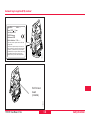
Leica TPS1100 Professional Series
User Manual
Version 2.2
English
Electronic total stations
Congratulations on your purchase of a TPS1100 Professional Series
instrument.
This manual contains important safety directions (refer to chapter
"Safety directions") as well as instructions for setting up the product
and operating it.
Read carefully through the User Manual before you switch on the
instrument.
2
TPS1100 - User Manual 2.2.1en
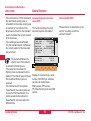
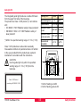
Product identification
The instrument model and the serial number of your product are indicated on
the label in the battery compartment.
Enter the model and serial number in your manual and always refer to this
information when you need to contact your agency or authorized service
workshop.
Type:
Serial number:
Software version:
TPS1100 - User Manual 2.2.1en
Language:
3
Product identification
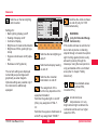
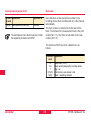
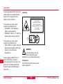
Symbols used in this manual
The symbols used in this User Manual have the following meanings:
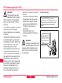
DANGER:
Indicates an imminently hazardous situation which, if not avoided, will
result in death or serious injury.
WARNING:
Indicates a potentially hazardous situation or an unintended use
which, if not avoided, could result in death or serious injury.
CAUTION:
Indicates a potentially hazardous situation or an unintended use
which, if not avoided, may result in minor or moderate injury and / or
appreciable material, financial and environmental damage.
Important paragraphs which must be adhered to in practice as they
enable the product to be used in a technically correct and efficient
manner.
Symbols used in this manual
4
TPS1100 - User Manual 2.2.1en
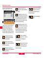
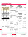
View of chapters
Contents
TPS1100 - User Manual 2.2.1en
6
Introduction
10
Description of the system
12
Preparation, setting up
22
Checking and adjusting
29
System functions
49
System parameters
97
Data format
108
Care and transport
119
Safety directions
121
Technical specifications
143
Index
156
5
View of chapters
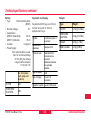
Contents
Introduction ................................................. 10
Checking and adjusting .............................. 29
Validity ....................................................................... 11
Documentation ........................................................... 11
Instrument descriptions ............................................. 12
Electronically ............................................................. 29
Compensator (electronic bubble) ................................... 32
V-index error ................................................................... 34
Line of sight .................................................................... 36
Tilting axis ....................................................................... 38
Combined error determination ........................................ 40
Deactivating the instrument-error correction ................... 40
ATR collimation ............................................................... 41
Description of the system........................... 12
Distance measurement .............................................
Extended Range (Option) ..........................................
Automatic Target Recognition ATR / LOCK ................
Quick Prism Search with PowerSearch ......................
Guide Light EGL ........................................................
RCS (Remote Controlled Surveying) ..........................
System concept .........................................................
Leica Survey Office PC software package ..................
Batteries and chargers ...............................................
13
14
15
15
16
17
18
20
21
Mechanically ............................................................. 44
Tripod ............................................................................. 44
Bull's eye bubble on instrument ...................................... 44
Bull's eye bubble on the tribrach ..................................... 44
Optical plummet ............................................................. 45
Laser plummet ................................................................ 46
Reflector-free EDM ......................................................... 47
Preparation, setting up ............................... 22
System functions ........................................ 49
Unpacking ................................................................. 22
Charging the battery .................................................. 23
Inserting / replacing battery ........................................ 24
Insert PC-card ........................................................... 26
Setting up the instrument with optical plummet or laser
plummet .................................................................... 27
Levelling-up with the electronic bubble ....................... 28
Contents
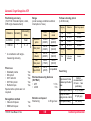
Data configuration ..................................................... 49
Data job (D JOB) and meas. job (M JOB) ....................... 49
Creating a new job (NEW) .............................................. 50
Codelist .......................................................................... 50
Creating a new codelist (NEW) ....................................... 51
Copying a codelist (COPY) ............................................. 51
Data management .......................................................... 51
Importing point data (IMPOR) ......................................... 53
Displaying and importing point data (VIEW) ................... 54
Displaying and editing GSI data (SEARC) ...................... 54
6
TPS1100 - User Manual 2.2.1en
Contents (continued)
Placeholder (wild cards) in searching for points .............. 55
Manual input of coordinates (INPUT) .............................. 56
Converting data .............................................................. 56
Formatting the PC-card (FORMT) ................................... 59
Inspecting the PC-card (PROOF) ................................... 60
Setting the recording mask (RMask) ............................... 60
Setting the display mask (DMask) ................................... 61
GSI-parameters .............................................................. 62
Last point number (L.Pt.) ................................................ 76
Deleting the GSI block (Del B) ........................................ 76
Manual distance entry ..................................................... 76
Positioning the last point stored (LAST) .......................... 77
V-angle modes ............................................................... 77
Offset .............................................................................. 78
Switching between display masks (>DISP) ..................... 78
Individual point number (INDIV / RUN) ........................... 79
Coding ............................................................................ 79
Quick Coding (QCod+ / QCod-) ..................................... 81
Check Orientation ........................................................... 82
GSI communication parameters ..................................... 83
Measurement functions ............................................. 66
Setting and entering the Hz direction (SetHz) ................. 67
Distance measurement ................................................... 67
Selecting the EDM measuring program,
target type and reflector .................................................. 68
Switch between IR/RL .................................................... 69
Switch between Standard/Tracking ................................. 70
Switch between Fast measurement/Rapid ...................... 70
Tracking .......................................................................... 70
Setting / defining prisms ................................................. 70
EDM test ......................................................................... 71
Distance corrections, ppm .............................................. 71
Reduced distance corrections ppm ................................. 73
Measurement & recording (REC) .................................... 73
Measuring distances and angles separately
(DIST + REC) ................................................................. 74
Measuring distances and angles together
with storage (ALL) .......................................................... 75
Storing station data (REC) .............................................. 75
Changing face (I<>II) ...................................................... 75
TPS1100 - User Manual 2.2.1en
Communication ......................................................... 83
Interface parameters (GeoCOM) .................................... 83
RCS communication parameters .................................... 84
On-line mode .................................................................. 84
Automatic Target Recognition .................................... 85
Functionality ................................................................... 85
ATR-Mode (ATR+ / ATR-) ............................................... 86
LOCK-Mode (LOCK+ / LOCK-) ....................................... 86
L.UNT-Mode (L.INT+ / L.GO) .......................................... 87
LAST mode (LAST) ........................................................ 88
Hz / V ............................................................................. 88
Automatic Reflector Search ....................................... 89
RCS Searching Window ................................................. 90
Definition of a Working Area (WORKA) .......................... 91
Activate/Deactivate Working Area (WORK+/WORK-) ..... 92
7
Contents
Contents (continued)
General functions ...................................................... 92
Coord. Seq. .................................................................. 100
Hz system ..................................................................... 100
Face I ........................................................................... 100
Compensator ................................................................ 101
Hz-Corr. ........................................................................ 101
Sect. Beep .................................................................... 102
Sect. Angle ................................................................... 102
Release V-angle ........................................................... 102
V-Display ...................................................................... 103
Power mode ................................................................. 103
Power Time .................................................................. 103
Dist. Delay .................................................................... 103
PPM entry ..................................................................... 104
Info / Atrib ..................................................................... 104
Auto Dist ....................................................................... 105
Instrument designation and software version (INFO) ...... 92
Electronic bubble (LEVEL) .............................................. 92
Illumination ..................................................................... 93
Accessories .................................................................... 94
Loading a configuration file (LOAD) ................................ 95
Loading a system-parameter file ..................................... 96
System parameters ..................................... 97
General parameters .................................................. 97
Load application ............................................................. 97
Load system language ................................................... 97
Date ................................................................................ 98
Date form. ....................................................................... 98
Time ............................................................................... 98
Alpha mode .................................................................... 98
Time form. ...................................................................... 98
Key beep ........................................................................ 98
Measurement parameters ....................................... 105
Pt. Id. mode .................................................................. 105
Offs. Mode .................................................................... 105
Increment ..................................................................... 106
Configuration parameters .......................................... 99
Work settings .......................................................... 107
Autoexec. ....................................................................... 99
Language ....................................................................... 99
Dist. Unit ......................................................................... 99
Dist. Dec. ........................................................................ 99
Angle Unit ....................................................................... 99
Angle Dec. ...................................................................... 99
Temp. Unit .................................................................... 100
Press. Unit .................................................................... 100
Contents
Meas Job ...................................................................... 107
Data Job ....................................................................... 107
Codelist ........................................................................ 107
Quick-Code .................................................................. 107
Data format ................................................ 108
Introduction ............................................................. 108
8
TPS1100 - User Manual 2.2.1en
Contents (continued)
Format with 8 or 16 characters ................................ 108
Block concept .......................................................... 109
Structure of a block ................................................. 109
Measurement block .................................................. 110
Code block ............................................................... 110
Terminator of a data block ........................................ 110
Structure of a word ................................................... 111
Limits of use ............................................................ 122
Responsibilities ....................................................... 123
Hazards of use ........................................................ 123
Main hazards of use ..................................................... 123
Laser classification .................................................. 127
Integrated distancer (infrared laser) ............................. 128
Integrated distancer (visible laser) ............................... 129
Automatic target recognition (ATR) ............................... 134
PowerSearch ................................................................ 136
Guide light EGL ............................................................ 137
Laser plummet .............................................................. 138
Word index (positions 1 - 2) ........................................... 111
Information relating to data (positions 3 - 6) .................. 112
Data (positions 7 - 15/23) ............................................. 113
Separating character (position 16/24) ........................... 114
Block number ............................................................... 114
Units of measurement .................................................. 115
Electromagnetic Compatibility (EMC) ....................... 140
FCC statement (applicable in U.S.) .......................... 142
Example of data format ............................................ 115
Technical specifications ........................... 143
Format of a theodolite measurement block ................... 116
Format of a code block ................................................. 118
EGL Guide Light ......................................................
Automatic Target Recognition ATR ..........................
PowerSearch ..........................................................
Application programs ...............................................
Scale correction (ppm) ............................................
Care and transport .....................................119
Transport ................................................................. 119
Maintainance for motorized drives ............................. 119
Storage ................................................................... 120
Cleaning and drying ................................................. 120
148
149
150
150
151
Atmospheric correction DD1 ......................................... 152
Reduction to mean sea level DD2 ................................ 153
Projection distortion DD3 .............................................. 153
Safety directions ....................................... 121
Intended use of instrument ...................................... 121
Atmospheric corrections .......................................... 154
Reduction formulae ................................................. 155
Permitted uses ............................................................. 121
Prohibited uses ............................................................. 121
Index ........................................................... 156
TPS1100 - User Manual 2.2.1en
9
Contents
Introduction
6
TPS1100 stands for Total Station
Positioning System. The TPS1100
instruments are available as various
models with differing classes of
accuracy. New technologies have
enabled the measuring sequence to
be largely automated, bringing
advantages such as shorter
measuring times, simpler operation
and more efficient use. Further
elements in the basic equipment are
described below.
The R versions have a laser with a
visible red beam. The EDM can be
switched between two operational
modes: measurements with normal
infrared or with the visible red laser
respectively. With the red laser,
reflectors are not required for
measuring distances. With infrared,
distances of up to seven kilometres
can be measured.
Introduction
All TPS1100 instruments are
routinely supplied with a laser
plummet located in the vertical axis.
The TPS1100 can therefore be set
up quickly and accurately over the
ground point with the help of the red
laser dot.
The A-versions have an automatic
target recognition (ATR), which
permits rapid, fatigue-free
measuring. In ATR mode the finepointing is automatic. In LOCK mode
an already-targeted point is tracked
automatically.
For TPS1100 plus instruments an
optional PowerSearch module is
available which allows an automatic
prism detection within a short period
of time.
The EGL guide light is an optional
accessory for assistance with
targeting. It is located within the
telescope and it flashes, so that the
person carrying the reflector can
10
place this in the line of sight of the
instrument.
The RCS1100 remote control system
is an additional option, which allows
the remote control of all total stations.
The instrument can be controlled
either directly on the instrument or at
the RCS1100. Especially the
A-versions enable the surveyor to
work alone.
The measurements can also be
triggered, inspected and controlled
from the target area.
Leica Geosystems offers
applications programs for many different tasks in surveying. Just
choose the software which best
meets your needs.
Within the special GeoBasic
programming environment, you can
create your own application-specific
programs for the TPS1100
instruments.
TPS1100 - User Manual 2.2.1en
The PC cards familiar in the
computer industry are also used as
the medium for storing data in the
TPS1100. The data structures are
compatible with those in existing Leica Geosystems total stations.
Validity
Documentation
This manual applies to all TPS1100
Professional Series instruments.
Printed short instructions for the
system and for the applications are
available as well as the present user
manual. The enclosed CD ROM
contains the entire documentation in
electronic form.
Differences between the various
models are clearly set out and
assigned.
General text applies to all types.
Leica Survey Office is a
PC-program package which supports
the TPS1100 and RCS1100
instruments and which enables data
to be exchanged between software
and hardware components.
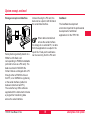
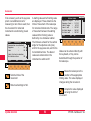
For purposes of pictorial illustration,
we have selected a TCA model of the
TPS1100 Professional Series with
EGL options. The illustrations are
valid for all models.
• User manual:
This includes all directions for
using the instrument and provides
an overview of the system together
with important instructions and
safety directions.
• System Field Manual:
This describes the functions of the
system in standard use (in
instrument case).
• Application Programs Field
Manual 1 + 2:
This describes the functions of the
programs in standard use (in
instrument case).
• Application Programs Reference
Manual:
All programs are described in detail.
TPS1100 - User Manual 2.2.1en
11
Introduction
6
Description of the system
0
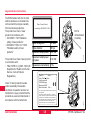
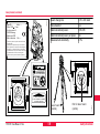
Instrument descriptions
1
2
3
10 11 12 13 14
Description of the system
4
15
5
6
16
7
8
17
9
18
19 20
12
1100Z01
6
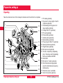
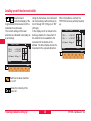
1 Carrying handle
2 Optical sight
3 Telescope with integrated EDM,
ATR, EGL and PowerSearch
4 EGL flashing diode (yellow)
5 EGL flashing diode (red)
6 Coaxial optics for angle- and
distance measurement;
Exit port of visible laser beam
(only R-model instruments)
7 PowerSearch sensor
8 Vertical drive screw
9 Focusing ring
10 PC-card housing
11 Horizontal drive screw
12 Footscrew (tribrach)
13 Display
14Tribrach securing knob
15 Keyboard
16 Batteryholder
17 Battery
18 Bull's-eye bubble
19 Laser emission indicator lamp only XR-instruments (yellow)
20 Interchangeable eyepiece
TPS1100 - User Manual 2.2.1en
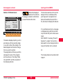
Distance measurement
For applications without reflector, the
TCR and TCRA version also use a
visible red laser beam which emerges
in the same manner. A special
arrangement of the EDM, and
appropriate arrangement of the beam
paths, enable ranges of over five
kilometres to be attained with standard
prisms; miniprisms, 360° reflectors, and
reflector tapes can also be used, and
measurement is also possible without a
reflector.
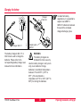
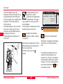
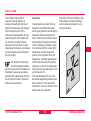
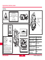
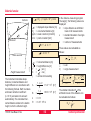
TPS1100 - User Manual 2.2.1en
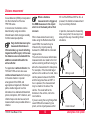
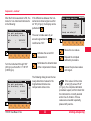
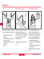
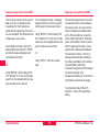
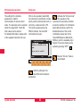
When measurements are being
made using the Reflectorless Red
Laser EDM, the results may be
influenced by objects passing
between the EDM and the intended
target surface.
This will occur because reflectorless
measurements are made to the first
surface returning sufficient energy to
allow the measurement to take place.
For example, if the intended target
surface is the surface of a road, but a
vehicle passes between the EDM
and the target surface as DIST or
ALL is pressed, the measurement
may be made to the side of the
vehicle. The result will be the
distance to the vehicle, not to the
road surface.
If you are using the Long Range Red
Laser EDM while measuring to a
prism, and an object passes within
13
30 m of the EDM as DIST or ALL is
pressed, the distance measurement
may be similarly effected.
In practice, because the measuring
time is very short, the surveyor can
always find a way of avoiding critical
situations.
Wrong result
1100Z46
Very short distances may be
measured reflectorless in
Infrared-mode (e.g. to well reflecting
targets like traffic signs). In this case
the distances are corrected with the
addition constant defined for the
active reflector.
When a distance
measurement is triggered,
the EDM measures to the object
which is in the beam path at that
moment.
Correct result
1100Z47
A laser distancer (EDM) is incorporated
into the instruments of the new
TPS1100 series.
In all versions, the distance can be
determined by using an invisible
infrared beam which emerges coaxially
from the telescope objective.
Description of the system
6
10
Extended Range (Option)
6
0
The optional "Extended Range (XR)"laser is a visible red laser with
in-creased measurement range. The
coaxial XR - laser makes it possible
to measure distances over 170 m
(560 ft) reflectorless and over 10 km
(6.2 miles) to one prism (refer to the
chapter "Technical specifications").
When a distance
measurement is triggered,
the EDM measures to the object
which is in the beam path at that
moment. In case of temporary
obstruction (e.g. a passing vehicle) or
heavy rain, fog or snow, the EDM
may measure to the obstruction.
Long Range to prisms
The operation of an XR - instrument
is equivalent to a conventional TPS
with red laser. Please consider the
following points when measuring with
the XR - laser (RL & Long Range).
When measuring longer distances, any divergence of
the red laser beam from the line of
sight might lead to less accurate
measurements. This is because the
laser beam might not be reflected
from the point at which the
crosshairs are pointing.
Whenever possible accurate
measurements to prisms
should be made with the standard
program (IR).
The objective lens should
always be clean. Dirt on the
lens (dust, fingerprints, ...) can lead
to reduced accuracy.
Reflectorless
Be sure that the laser beam
is not reflected by anything
close to the line of sight (e.g. highly
reflective objects).
Description of the system
Therefore, it is recommended to verify that the XR - laser is well collimated with the telescope line of sight
(refer to the chapter "Checking and
adjusting"). This should be done at
regular intervals.
WARNING:
Due to laser safety
regulations and measuring
accuracy, using the Long Range Program is only allowed to prisms that
are more than 1000 m (3300 ft) away.
Long Range to reflector tape
The Long Range Program can also
measure to reflector tape. To guarantee the accuracy the laser beam
must be perpendicular to the reflector
tape and the XR - laser must be well
adjusted (refer to the chapter
"Checking and adjusting").
Do not measure with two
instruments to the same
target simultaneously.
14
TPS1100 - User Manual 2.2.1en
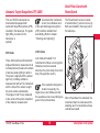
Quick Prism Search with
PowerSearch
Automatic Target Recognition ATR / LOCK
ATR mode
These instruments permit automatic
angle and distance measurements to
normal prisms and reduce the tedium
of precise visual sighting to prisms.
The prism is sighted with the optical
sight only. Initiating a distance
measurement will turn the instrument
with the help of the motors to sight
the prism-centre automatically.
The angles V and Hz are measured
to the centre of the prism completion
of the distance measurement.
TPS1100 - User Manual 2.2.1en
As with all other instrument
errors, the collimation error
of the automatic target recognition
(ATR) must be redetermined
periodically (Refer to chapter
"Checking and Adjusting").
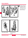
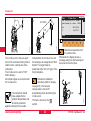
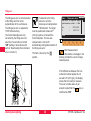
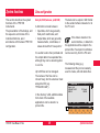
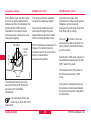
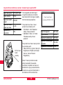
The PowerSearch sensor consists
of a transmitter (1) and a receiver (2).
Both are installed in the lower part of
the telescope.
LOCK mode
1
Lock mode will enable TCA
instruments to follow a moving prism.
Distances can be measured
whenever the prism stops for a short
time ("Stop and Go mode").
If the assistant changes the
location too quickly, the
target may be lost. Make sure that
the speed does not exceed the figure
given in the technical data.
15
2
1100Z55
TCA and TCRA instruments are
motorized and equipped with
Automatic Target Recognition (ATR)
coaxially in the telescope. The guide
light (EGL), mounted on the
telescope, is
optional.
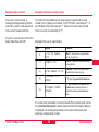
When PowerSearch is activated, the
instrument starts to rotate around its
standing axis.The transmitter emits a
vertical laser swath.
Description of the system
6
10
PowerSearch can be started at any
time by pressing the PowerSearch
function key (PS) in the menu PROG.
If RCS mode is activated, then
PowerSearch can be switched on
during an ATR prism search.
Working range:
Swath divergence Hz:
Swath divergence V:
Description of the system
5-200 m
0.025 gon
±20 gon
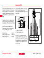
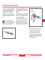
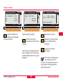
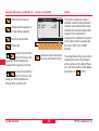
The optionally available Guide Light
EGL consists of two coloured
flashing lights in the telescope of the
total station.
2
100 m (330 ft)
0
If the laser swath detects a prism, the
reflection is detected by the receiver
and the rotation of the instrument is
stopped. Afterwards a fine aiming in
vertical direction is performed by the
ATR.
1
1100Z02
6
1100Z03
Guide Light EGL
1 Flashing red diode
2 Flashing yellow diode
All TPS1100 instruments can be
equipped with this Guide Light. The
person at the prism can be guided by
the flashing lights directly to the line
of sight. It becomes much easier to
set out points.
16
6m
(20 ft)
6m
(20 ft)
TPS1100 - User Manual 2.2.1en
RCS (Remote Controlled Surveying)
At a target distance of 100 metres
(330 ft) a red/yellow flashing cone of
light with a width of 6m (20 ft) is
formed on each side. As a result,
guiding to the line of sight of the
instrument is much easier and faster.
The RCS option (Remote Controlled
Surveying) permits all models to be
controlled from the target area.
Especially qualified for this purpose
are the TCA and TCRA instruments.
Between the two cones of light a
sector about 30mm wide is created.
Within this sector both colours are
flashing simultaneously. In this case
the prism is already right in the line of
sight.
Combined operation, partly at the
TPS1100 and partly at the prism, is
also possible.
As a result, surveys can be
performed solo. It is also possible to
monitor the operation on the RCS
1100 and / or to enter the coding on
the RCS 1100.
All functions of the TPS1100,
including the applications programs,
are available on the RCS 1100. The
display and the use of the keys are
as for the TPS1100.
Operating range:
5 - 150 m (15 -500 ft)
Divergence:
10 m (33ft) at 100m (330 ft)
For further information, refer
to the RCS1100 user
manual.
RCS 1100
TPS1100 - User Manual 2.2.1en
17
Description of the system
6
10
6
0
All of TPS 1100 models use the
same software architecture and the
same concept for data storage and
data flow.
Software architecture
The software of the TPS1100 can be
divided into two groups:
• The system software, which
covers the basic functions
• The applications software, which
supports survey- specific
applications and procedures.
The system software forms a
coherent unit, whereas the
applications software can be
compiled in accordance with the
individual requirements of the user.
Using the Leica Survey Office
software provided, both the system
software and the applications
software can be loaded across the
serial interface by the user, who is in
a position to install improved
software versions.
Description of the system
18
1100Z04
System concept
Systemsoftware,
Applications
Data
Survey Office
The software permits up to three
languages to remain stored
simultaneously and one of them to be
selected. The range of language
versions available is constantly being
expanded. If you need a particular
language version, please ask your
agency about its availability.
TPS1100 - User Manual 2.2.1en
System concept, continued
1100Z05
Storage concept and data flow
Survey data is generally stored on a
SRAM or ATA flash card
corresponding to PCMCIA standards
(referred to here as a PC card). The
data are stored in MS-DOS file
format. Data is exchanged with a PC
through either a PCMCIA drive on
that PC, or an OMNI drive (optional),
or the serial interface (cable link
between instrument and PC).
The Leica Survey Office software
supplied with the instrument includes
a program for transferring data
across the serial interface.
TPS1100 - User Manual 2.2.1en
Instead of using the PC card, the
data can be output in GSI format at
the serial data interface.
GeoBasic
6
The GeoBasic development
environment permits the professional
development of additional
applications for the TPS1100.
When data is transferred
across the serial interface
for storage in an external PC, no data
from the applications is output in the
report file. Fixed-point coordinates
can be read only from the PC card.
19
Description of the system
10
Leica Survey Office PC software package
6
0
The Leica Survey Office software
includes a series of help programs
which support you in your work with
the TPS1100 total station.
Installing in the PC
The installation program for Leica
Survey Office is located on the
TPS1100 CD-ROM supplied with the
present handbook. Please note that
Survey Office can only be installed on
the following operating systems:
MS Windows 95/98/Me and
MS Windows NT4.0/2000/XP.
To install the program, first call up the
program "setup.exe" from the
directory \SurveyOffice\
English\Disk1\ on the CD-ROM, and
carry out the instructions given. For
further information, refer to the
handbook or to the on-line help
provided by your operating system.
Description of the system
Range of programs
After the installation is complete, the
following programs are available:
• Data Exchange Manager:
Exchange of data between the
instrument and the PC.
• Codelists Manager:
Creates code lists.
• Software Upload:
Loading and deleting systems
software, applications programs,
systems texts and applications
texts.
• Coordinate Editor:
Editing of coordinates.
For additional information
about Leica Survey Office,
please refer to the
comprehensive on-line help.
Optionally, additional programs can
be installed.
20
TPS1100 - User Manual 2.2.1en
Batteries and chargers
Vehicle battery cable
Charger
GKL122
6
Charger
GKL23
10
Power cable
Your Leica Geosystems instrument is
powered by rechargeable battery
modules. The Pro battery (GEB121)
is recommended for the TPS1100
Professional Series. The basic
battery (GEB111) is an optional alternative.
Use only the Leica Geosystems batteries, chargers and
accessories, or accessories
recommended by Leica Geosystems.
TPS1100 - User Manual 2.2.1en
The Professional charger (GKL122)
will charge up to four batteries, either
from a 230V or 115V power source
using a power plug or from the 12V
or 24V source provided by the
cigarette lighter in a vehicle. At any
one time, either two Pro / Basic
batteries can be charged or, by using
the adapter plate (GDI121), four Pro /
Basic batteries.
21
Adapter plate
GDI121
1100Z08
Charging cable
Adapter plate
GDI121
1100Z07
GEB121
1100Z06
GEB111
The adapter plate GDI121 can be
connected to the Pro charger
(GKL122) or to the GKL23 charger,
and enables two Pro / Basic batteries
to be charged simultaneously.
Description of the system
Preparation, setting up
Unpacking
0
Take the instrument out of the transport container and check that it is complete:
2
1100Z09B
6
1
2
3
10
11
4
12
13
14
5
15
6
7
16
8
17
9
Preparing to measure, setting up
18
22
1 PC cable (optional)
2 Eyepiece for steep sights / Zenith
eyepiece (optional)
3 Counterweight for eyepiece for
steep sights (optional)
4 Charger GKL111 (optional)
5 PC card (optional)
6 Pocket knife (optional)
7 Auxiliary lens (optional)
8 Spare battery (optional)
9 Power plug for GKL111 (optional)
10 Spacing bracket (optional)
11 Height meter (optional)
12 Mini prism rod (optional)
13 Tool set, comprising 2 adjusting
pins, 1 Allen key each for adjusting
bull's-eye bubble and EDM.
14 Instrument
15 Mini prism + holder (optional)
16 Short instructions/ target plate
(only for reflectorless measuring
instruments)
17 Protective cover, sunshade
18 Tip for mini prism (optional)
TPS1100 - User Manual 2.2.1en
Charging the battery
To attain full battery
capacitance, it is essential to
subject new GEB111 /
GEB121 batteries to between
three and five complete
charge/discharge cycles.
The battery chargers GKL111 or
GKL122 are used to charge the
batteries. Please refer to the
corresponding battery charger user
manual for more information.
TPS1100 - User Manual 2.2.1en
1100Z07
Charger GKL111
1100Z10
Charger
GKL122
Adapter plate
GDI121
WARNING:
The battery chargers are
intended for indoor use only.
Use the battery charger in a dry room
only, never outdoors. Charge
batteries in an ambient temperature
between 0°C and 35°C ( 32°F to
95°F ). We recommend a
temperature of 0°C to +20°C (32°F to
68°F) for storing the batteries.
23
Preparing to measure, setting up
6
10
12
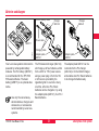
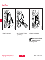
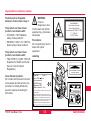
Inserting / replacing battery
Insert battery correctly (note
pole markings on the inside
of the battery cover). Check
and insert battery holder true
to side into the housing.
6
0
3. Insert battery into battery holder.
2. Remove battery and replace.
Preparing to measure, setting up
1100Z12
1100Z49
1. Remove battery holder.
1100Z50
1100Z48
2
4. Insert battery holder into
instrument.
24
TPS1100 - User Manual 2.2.1en
External power supply for total station
TPS1100 - User Manual 2.2.1en
6
10
12
For assembling open up one ferrite
core and clip it around the supply
cable, about 2cm away from the
Lemo plug, before using the supply
cable for the first time together with a
TPS1100 instrument.
1100Z57
The Lemo plug with the
ferrite core always has to be
attached at the instrument side.
The cables supplied along with your
instrument include a ferrite core as
standard.
If you are using older cables without
ferrite core, it's necessary to attach
ferrite cores to the cable.
If you need additional ferrite cores,
please contact your local Leica Geosystems agency. The spare-part
number of the ferrite core is 703 707.
1100Z58
To meet the conditions stipulated for
electromagnetic acceptability when
powering the TPS1100 from an
external source, the supply cable
used must be equipped with a ferrite
core.
25
Preparing to measure, setting up
Insert PC-card
6
1
2
5
4
2
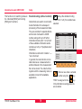
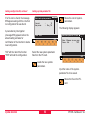
1. Open PC-card housing.
2. Insert PC-card with TPS- arrow
symbol facing up.
1100Z53
1100Z51
3
1100Z52
0
3. Closing PC-card housing.
When closing the PC-card
housing the connector
must face upwards!!
Preparing to measure, setting up
26
TPS1100 - User Manual 2.2.1en
Setting up the instrument with optical plummet or laser plummet
6
1
6
1
Tribrach GDF121
or GDF122
Tripod GST120
12
3
2
4
4
1
1100Z13
1100Z14
2
1. Target the ground point or activate
the laser plummet.
2. Set up the GST20, centring it as
well as possible.
3. Using the footscrews of the
tribrach, centre the plummet to the
ground point.
The laser plummet is built into the
vertical axis of the TPS1100
instruments. Projecting a red dot on
to the ground makes it appreciably
easier to centre the instrument.
TPS1100 - User Manual 2.2.1en
4. Move the legs of the tripod to
centre the bull’s-eye bubble.
The laser plummet cannot be
used in conjunction with a
tribrach which already has an
optical plummet.
27
4
1100Z15
2
10
5/8"-thread
5. Level-up precisely, using the
electronic bubble (see the chapter
"Levelling-up with the electronic
bubble").
6. Centre precisely by shifting the
tribrach on the tripod plate.
Repeat steps 5 and 6 until the
required accuracy is reached.
Preparing to measure, setting up
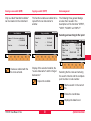
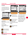
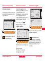
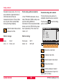
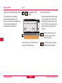
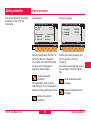
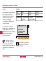
Levelling-up with the electronic bubble
2
Elect. Level
Tilt L
Tilt T
: -0°03'40"
: -0°18'30"
L.Plumet : 50%
CONT
Using the footscrews, the instrument
can be levelled-up without having to
turn it through 90° (100 gon) or 180°
(200 gon).
In the display which is closest to the
bull's-eye bubble, the movement of
the small circle runs parallel to the
movement of the bubble in the
alidade. The other display shows the
movement in the opposite direction.
When the bubble is centred, the
TPS1100 has been perfectly levelled
up.
Elect. Level
Tilt L
Tilt T
: -0°00'10"
: -0°00'20"
L.Plumet : 50%
CONT
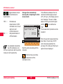
MC
0
Graphical and
numerical display of the
longitudinal and transverse tilt of the
instrument’s vertical axis.
The current settings of the laser
plummet are indicated numerically as
a percentage.
MC
6
X
L.Pl+
QUIT
X
L.Pl+
QUIT
Switches the laser plummet
on or off.
Varies the intensity of the
laser dot.
Preparing to measure, setting up
28
TPS1100 - User Manual 2.2.1en
Checking and adjusting
6
Electronically
All instruments basically have
inherent mechanical defects which
can affect the measurement of
angles. The electronic anglemeasuring system of the TPS1100
routinely corrects the mechanical
instrument errors listed below; the
vertical angles relate to the plumb
line and the horizontal measurements
are corrected for line-of-sight error,
for tilting-axis error and for verticalaxis tilt:
• l, t
•i
•c
•a
• ATR
Compensator index error
Vertical-index error
Line-of-sight error
Tilting-axis error
ATR zero-point error (only for
TCA and TCRA versions)
TPS1100 - User Manual 2.2.1en
The instrument errors listed on the
left can change over time and with
temperature.
They should, therefore, be
redetermined in the order shown
below:
• before the first use
• before each precision survey
• after long periods of transport
• after long periods of work
• if the temperature alters by more
than 20°C
Before determining the instrument
errors, level-up the instrument using
the electronic bubble. The instrument
should be secure and firm, and
should be protected from direct
sunlight in order to avoid thermal
warming on one side only.
29
Take note that the procedure
for determining the relevant
instrument error has to be followed
precisely and carefully.
10
The determination of the
instrument errors can be
started in any telescope face.
21
Immediately after the first
measurement has been
completed, motorized instruments
change automatically to the second
face, after which the user merely
needs to carry out the fine pointing.
Checking and adjusting
12
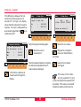
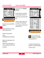
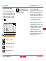
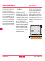
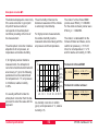
Electronic checking and adjusting, continued
0
2
21
Activating the "Instrument calibration"
function.
Main\
l
t
i
c
a
Instr. calibration
current
Compens.long.:
0°00'37"
Compens.trans:
-0°00'34"
V-index error:
0°00'28"
Hz-coll.error:
0°00'20"
Tilting-axis :
0°00'26"
l,t
i
MC
6
c/a i/c/a ATR + EXIT
LOGF+
QUIT
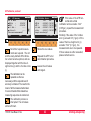
Determines the compensator
index error.
Simultaneous adjustment of
the electronic bubble.
Joint determination of the Vindex errors, line-of-sight
errors and, if required, tiltingaxis errors.
Determines the collimation
error of the ATR
(TCA and TCRA versions
only).
The instrument errors reported are
displayed in the sense of an error.
When measurements are being
corrected, they are used in the sense
of corrections and have the opposite
sign to the error.
Enables the calibration
Log-file (see next
page).
Determines the index error
for the vertical circle
(V-index error).
Defines line-of-sight errors
and, if required, tilting-axis
errors.
Checking and adjusting
30
TPS1100 - User Manual 2.2.1en
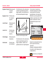
Electronic checking and adjusting, continued
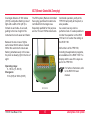
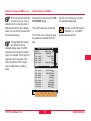
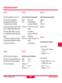
Calibration Log-File
If the Log-File is enabled [LOGF+],
the measurements and results of the
calibration are stored in an ASCII-file.
This file is created in the directory
LOG on the memory card.
Subsequently, you can read the
memory card on your PC and obtain
a hard copy of the Log-file.
10
Compensator Index Error l,t
Date/Time
:
03/04/2000
Old values
:
Measurements
New values
New data is always
appended to the calibration
Log-file.
6
TPS1100 - Instrument Calibration
Instrument
: TCRA1102plusSerial 619216
:
l=
0.0000g
t=
0.0000g
L= -0.0126g
L= 0.0368g
T=
T=
0.0298g
0.0164g
l=
t=
0.0023g
V=
V=
104.2828 g
295.7176 g
0.0010g
Vertical Index Error i
Date/Time
:
03/04/2000
Old value
:
Measurements
i=
15:45
0.0000g
Hz= 377.0597 g
Hz= 177.0562 g
New value
:
12
15:43
i=
0.0001g
Example of a Calibration Log-file (here compensator and vertical index errors)
TPS1100 - User Manual 2.2.1en
31
Checking and adjusting
21
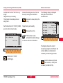
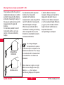
Compensator (electronic bubble)
Activate the calibration
procedure. (Refer to display
on page 30)
Vertical axis
0
The longitudinal and transverse axes
(l, t) are displayed afterwards in the
following dialog.
2
l
q
1100Z01
21
The determination of the index error
for the longitudinal and transverse
axes of the compensator ( l, t )
corresponds to the determination of
the centre of the bubble used in the
level.
The instrument should be
set up away from warmth
coming from one side some
time before the calibration
so that it can adjust to the ambient
temperature.The index error for the
longitudinal and transverse axes is
determined at the factory and adjusted
to zero before delivery.
Checking and adjusting
Main\ Compens.Index Error
1st tilt measurement in any
face
L Compens.:
T Compens.:
MC
6
0°00'25"
0°00'04"
MEAS
QUIT
Initiate the measurement of
the longitudinal and
transverse tilt ( l, t ).
32
If the tilt cannot be measured, e.g.
due to an unstable instrument, the
error message ERROR: 557 is
displayed and the following keys are
defined:
Repeat measurement.
Abort measurement.
Non-motorized instruments perform
the second measurement after the
alidade of the instrument has been
turned 180° (200 gon), with an
accuracy of ±4° 30' (±5 gon).
After the initial measurement has
been started by pressing the key
, motorized instruments will
automatically complete the
determination of l and t without any
other assistance.
The following dialog is displayed after
completing the first tilt measurement
with non-motorized instruments.
TPS1100 - User Manual 2.2.1en
After the first measurement of tilt, the
menu for non-motorized instruments
is the following:
∆ Hz
∆V
:
:
MC
Telescope Positioning
Hz- and V-positioning:
set direction(s) to zero.
ABORT
Terminates the determination
of the compensator indexes.
∆ Hz
∆V
:
:
0°00'00"
-----OK
MC
Telescope Positioning
Hz- and V-positioning:
set direction(s) to zero.
II
The following dialog shows the two
newly-determined values for the
longitudinal and transverse
compensator-index errors.
ABORT
QUIT
TPS1100 - User Manual 2.2.1en
l Comp:
t Comp:
new
0°03'02"
-0°02'06"
YES
RETRY
33
6
10
NO
QUIT
Stores the new values.
Activates the second tilt
measurement.
Turn the instrument through 180°
(200 gon) so that ∆Hz = 0° 00' 00"
(0.0000 gon).
Main\ Compens.Index Error
Accept new value(s)?
The user is made aware by an
-key is
acoustic signal that the
redefined as "OK".
180°00'00"
-----OK
If the differences between the horizontal and vertical angles lie within
±4° 30' (±5 gon), the display can be
quitted with
.
MC
Compensator , continued
Repeats the complete
calibration procedure.
Leaves the previous values
unchanged.
If the values for the index
errors (l, t) exceed 5' 24"
(0.1 gon), the complete calibration
procedure repeat, but first check that
the instrument is correctly levelled
and is free of vibration. If these
values are exceeded repeatedly,
please notify service.
Checking and adjusting
12
21
6
i
1.
Main\
V-Index Error
Aim accurately at a target
positioned at a dist. >100m
ca. 100m
0
Hz
V
+/-9°
2
:
:
MC
V-index error
343°18'54"
93°47'41"
MEAS
QUIT
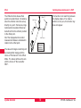
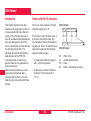
The V-index error is the zero-point
error of the vertical encoding circle in
relation to the vertical axis of the
instrument.
The V-index error is set to "0.00"
before delivery.
All vertical angles are corrected with
the V-index error.
The instrument should
have adapted to the
ambient temperature and
should be protected
against warming from one side.
Checking and adjusting
To determine the V-index error, aim
the telescope at a target about 100m
distant. The target must be
positioned within ±9° (±10 gon) of the
horizontal plane.
Activate the calibration
procedure (Refer to display
on page 30). The two-axis
compensator is turned off
automatically when determining the
V-index error.
This fact is shown by the
symbol.
34
Starts the measurement for
the vertical circle.
Afterwards, the display shows a
message asking for the telescope to
be turned to the other face.
2.
180°
180°
1100Z19
1100Z17
1100Z18
21
TPS1100 - User Manual 2.2.1en
V-index error , continued
Telescope Positioning
Hz- and V-positioning:
Set direction(s) to zero.
∆ Hz
∆V
:
:
MC
Hz
V
:
:
163°18'54"
266°12'19"
MC
V-Index Error
old
new
0°00'03" -0°00'22"
Accept new value(s)?
MEAS
YES
RETRY
QUIT
Sight the target accurately again.
After the measurements are complete,
the older and newly-determined Vindex errors are displayed.
Confirms the readiness to
measure and changes the
display.
NO
QUIT
Stores the new values.
Repeats the complete Vindex error determination
procedure.
Leaves the old values
unchanged.
If the value of the V-index
error (i) exceeds 54' (1 gon)
you should repeat the measurement
procedure. If this value is exceeded
repeatedly, please contact service.
35
6
10
ABORT
QUIT
TPS1100 - User Manual 2.2.1en
Main\
i Vind:
Starts the second
measurement.
0°00'00"
0°00'00"
OK
Main\
V-Index Error
Aim accurately at the same
target in other face
MC
If the differences between the horizontal and vertical angles do not
exceed ±27' ( ±0.5 gon ), the display
shows that the instrument is ready to
measure. The user is made aware by
an acoustic signal that the
key is
redefined as 'OK'.
Checking and adjusting
12
21
0
2
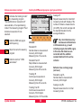
21
The line-of-sight error c is the
divergence of the line of sight from a
line perpendicular to the tilting axis.
The line-of-sight error is adjusted and
reduced to "0.00" before delivery
from the factory.
Horizontal angles are only corrected
by this line of sight error when the
correction is turned "ON" (setting in
accordance with section
"Deactivating the instrument-error
correction").
Activates the calibration
procedure. (Refer to display
on page 30).
The two-axis compensator is turned
off automatically when determining
the line-of-sight error.
f
eo
n
i
L ht
sig
c
To determine the line-ofsight error, aim the
telescope at a target about
100m distant. The target
must lie within ±9° (±10 gon) of the
horizontal plane.
The procedure is analogous to that of
determining the V-index error.
This fact is shown by the
symbol.
Til
tin
ga
xis
1100z20
6
Checking and adjusting
36
Main\
Hz-collim. Error
Aim accurately at a target
positioned at a dist. >100m
Hz
V
:
:
MC
Line of sight
373°19'24"
90°51'15"
MEAS
QUIT
Perform the measurement.
Afterwards, a message in the display
prompts you to change telescope
face.
If the differences between the horizontal and vertical angles do not
exceed ±27' ( ±0.5 gon ), the display
shows that the instrument is ready to
measure. The user is made aware by
an acoustic signal that the
key
is redefined as "OK".
TPS1100 - User Manual 2.2.1en
Line of sight, continued
0°00'00"
0°00'00"
OK
ABORT
QUIT
Hz
V
:
:
c Hz-c:
Hz-Collim. Error
old
-0°00'03"
new
0°00'08"
Main\
Hz-Collim. Error
Continue to determine the
tilting-axis errror?
YES
RETRY
NO
YES
NO
MC
QUIT
193°19'24"
269°08'45"
MEAS
Stores the new values.
Repeats the complete line-ofsight error determination
procedure.
Leaves the old values
unchanged.
Confirms that the tilting-axis
error should also be
determined.
Ends the function and returns
to the calibration dialog.
QUIT
Sight the target accurately.
Perform the second
measurement.
TPS1100 - User Manual 2.2.1en
If the value of the line-ofsight error (c) exceeds 5' 24"
(0.1 gon), the collimation error is to
be redetermined. If the limit is
repeatedly exceeded, please notify
service.
37
6
10
12
21
Accept new value(s)?
Confirms readiness for
measurement and goes to
the measuring menu.
Main\
Hz-collim. Error
Aim accurately at the same
target in other face
Main\
When the new line-of-sight error has
been confirmed, the tilting-axis error
can be determined.
MC
:
:
After successful completion of the
second measurement, the older and
the newly-determined line-of-sight
errors are displayed.
MC
∆ Hz
∆ V
MC
Telescope Positioning
Hz- and V-positioning:
set direction(s) to zero.
Checking and adjusting
0
2
21
The tilting-axis error a is the deviation
of the tilting axis from a line
perpendicular to the vertical axis.
The tilting-axis error is adjusted to
"0.00" before delivery.
The horizontal angles are only
corrected by the tilting axis error
when the Hz-correction is turned
"ON" (setting in accordance with
section "Deactivating the instrumenterror correction").
To determine the tiltingaxis error, aim the
telescope at a target about
100m distant. The target
must be positioned at least ±27°
(±30 gon) above or beneath the
horizontal plane. The two-axis
compensator is turned off
automatically during determination of
the tilting-axis error.
This fact is shown by the
symbol.
Main\
Tilting-Axis Error
Aim accur. at high/low target
positioned at a dist. > 100m
Hz
V
:
:
373°19'24"
90°51'15"
MEAS
QUIT
Start measurement.
Afterwards, a message in the
display prompts the user to change
telescope face.
Vertical axis
Til
tin
ga
If the differences between the horizontal and vertical angles do not
exceed ±27' (±0.5 gon), the display
shows that it is ready to measure.
The user is made aware by an
acoustic signal that the
key is
redefined as "OK".
xis
a
1100Z21
6
MC
Tilting axis
Checking and adjusting
38
TPS1100 - User Manual 2.2.1en
∆ Hz
∆V
:
:
0°00'00"
0°00'00"
OK
Main\
Tilting-Axis Error
Aim accurately at the same
target in other face
Hz
V
ABORT
:
:
a Tilt:
193°19'24"
269°08'45"
old
new
-0°00'03" 0°00'17"
YES
RETRY
QUIT
NO
QUIT
Stores the new values.
Performs the second
measurement of the horizontal angle.
Repeats the complete tiltingaxis error determination
procedure.
39
6
10
Sight the target accurately.
After the second measurement has
been completed, the old and newlydetermined tilting-axis errors (a) are
displayed.
TPS1100 - User Manual 2.2.1en
Tilting-Axis Error
Accept new value(s)?
MEAS
QUIT
Confirms readiness to
measure and the display
changes as follows.
Main\
MC
MC
Telescope Positioning
Hz- and V-positioning:
set direction(s) to zero.
MC
Tilting axis, continued
Leaves the old values
unchanged.
If the value of the tilting axis
error (a) exceeds 5' 24"
(0.1 gon), the measurements are to
be repeated. If this happens often,
please notify service.
Checking and adjusting
12
21
0
2
21
Deactivating the instrument-error correction
By using the key
in the display
on page 30, it is possible to
determine the errors for vertical
index, line of sight and tilting axis (i/c/
k) with a single operation.
Also the mechanical instrument-error
correction can be deactivated if the
need is to display and record only
raw data. To deactivate, set the
compensator correction and the
horizontal-circle correction to OFF,
i.e. the vertical angles relate to the
vertical axis and the horizontal
corrections are not taken into
account.
The V-index and line-of-sight errors
can be determined using a common
target which does not lie more than ±
9° (± 10 gon) away from the horizontal plane. The determination of the
tilting-axis error requires a target
which lies at least ± 27° (± 30 gon)
above or beneath the horizontal
plane.
Main\
Compensator
Compensator ON/OFF
Hz corrections ON/OFF
compensat.:
Hz-corr. :
ON
ON
For exact procedural details,
please refer to the previous
chapters.
Checking and adjusting
MC
6
Combined error determination
QUIT
40
TPS1100 - User Manual 2.2.1en
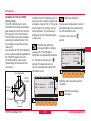
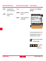
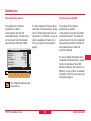
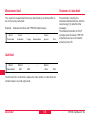
ATR collimation
Hz-component
Centre
of prism
Activates the calibration
procedure (Refer to display
on page 30). The ATR target
recognition is automatically switched
on. This fact is shown by the
symbol. The display shows the
current horizontal and vertical ATR
collimation errors.
CAL\ ATR Collim. Errors
ATR Hz-coll.err:
ATR V-coll.err:
V-component
actual
0°00'05"
0°00'10"
Starts the calibration.
6
The two-axis compensator is turned
off automatically when determining
the ATR collimation error.
10
This fact is shown by the
symbol.
CAL\ ATR Collim. Errors
Aim accurately at a target
positioned at a dist. >100m
Hz
:
V
:
Determ.c/i:
73°25'36"
88°45'14"
▼
NO▼
MEAS
QUIT
Sight the prism accurately with the
crosshair.
Starts the measuring
procedure.
CONT
QUIT
1100Z30
Crosshair
TPS1100 - User Manual 2.2.1en
41
12
21
MC
To define the ATR collimation error, a
prism must be accurately targeted at
a distance of about 100 m. The target
must lie within ±9° (±10 gon) of the
horizontal plane. The procedure is
analogous to that of determining the
V-index error.
MC
(Available for TCA and TCRA
versions only)
The ATR collimation error is the
combined horizontal and vertical angular divergence of the line of sight
from the axis of the CCD camera.
The collimation procedure includes,
optionally, the determination of the
line-of-sight error and the verticalindex error.
The correction for the ATR collimation
errors is always applied regardless of
the "ON/OFF" status of the Hzcorrection setting. (See section
"Deactivating the instrument-error
correction").
Checking and adjusting
ATR collimation, continued
0
2
Toggles between simple
and combined error
determination.
YES =
21
NO
=
Simultaneous
determination of ATRcollimation error, line-ofsight error and
vertical-index error
Only determination of
ATR-collimation
Changes face automatically
directly after completing the initial
measurement.
CAL\ ATR Collim. Errors
Aim accurately at the same
target in other face.
Hz
V
:
:
MC
6
253°25'36"
271°14'46"
MEAS
QUIT
It is advisable to determine
the ATR-collimation error,
the line-of-sight error and the verticalindex error at the same time.
Sight the prism accurately with the
crosshair.
If the differences between the horizontal and vertical angles exceed
±27' ( ±0.5 gon ), the display gives an
error message. The user is made
aware of this by an acoustic signal
and the
key is redefined as
"OK".
The measurement procedure can be
repeated.
When the second measurement has
been taken, the accuracy of ATR
and, if previously selected, the
accuracy of the index and the line-ofsight errors are displayed.
Performs the second-face
measurement of the
collimation errors.
Checking and adjusting
42
TPS1100 - User Manual 2.2.1en
CONT
MORE
ABORT
No further repeat measurements are required. The old
and the newly-defined ATR-collimation errors become optional, and are
displayed together with the line-ofsight errors (c) and the V-index errors
(i).
The calibration can be
repeated as often as
necessary until the required level of
accuracy is obtained. The result is the
mean of all the measurements taken.
It is recommended that at least two
measuring sequences be carried out.
The calibration process is
interrupted. The old values
will be left intact.
TPS1100 - User Manual 2.2.1en
CAL\ATR Collim. Errors
old
new
ATR Hz
: 0°00'08" 0°00'05"
ATR V
: 0°00'10" 0°00'09"
i V-ind
: 0°00'00" 0°00'10"
c Hz-c
: 0°00'10" 0°00'02"
Accept new value(s)?
YES
RETRY
MC
CAL\
ATR Accuracy
No. of Meas:
2
σ ATR Hz
:
0°00'05"
σ ATR V
:
-0°00'08"
σ i V-Ind. :
----σ c Hz-col :
----Take more measurements?
MC
ATR collimation, continued
NO
Stores the new values.
Repeats the ATR1 error
determination procedure.
If the value of the ATR horizontal and vertical
collimation errors exceeds 2' 42"
(0.05 gon), repeat the measurement
procedure.
Similarly, if the value of the V-index
error (i) exceeds 54' (1 gon) or if the
value of the line-of-sight error (c)
exceeds 5' 24" (0.1 gon) , the
measurements are to be repeated.
If these values are often exceeded,
please contact service.
Leaves the old values
unchanged.
43
Checking and adjusting
6
10
12
21
Mechanically
6
Tripod
0
1
Bull's eye bubble on instrument
Bull's eye bubble on the tribrach
2
2
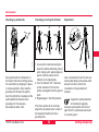
The connections between timber and
metal must always be firm and tight.
• Moderately tighten the Allen
screws (2).
• Tighten articulated joints (1) just
enough to keep the
tripod legs open when you lift the
tripod off the
ground.
Checking and adjusting
Level-up the instrument in advance
with the electronic bubble. The
bubble must be centred. If it extends
beyond the circle, use the adjusting
pin supplied to centre it with the
adjustment screws.
After adjustment no screw shall be
loose.
44
1100Z24
1100Z23
1100z22
21
Level the instrument and then
remove it from the tribrach. If the
bubble is not centred, adjust it using
the adjusting pin in conjunction with
the two cross-headed adjustment
screws (GDF121 bzw. GDF122).
Turning the adjustment screws:
• to the left: the bubble approaches
the screw
• to the right: the bubble goes in the
other direction.
After adjustment no screw shall be
loose.
TPS1100 - User Manual 2.2.1en
Optical plummet
Checking by plumb-bob:
Checking by turning the tribrach
2
1
120°
Adjustment
6
3
10
120°
12
Set-up and level the instrument on
the tripod. Check the centring sleeve
for eccentricity by hanging it in place
in various positions, then mark the
ground point. Remove the plumbbob. Check that the crosshairs of the
optical plummet intersect at the
ground point. The accuracy
achievable is about 1mm.
TPS1100 - User Manual 2.2.1en
1. Level-up the instrument using the
electronic bubble. Mark the ground
point. Using a soft, well-sharpened
pencil, mark the outline of the
tribrach on the tripod plate.
2. Turn the tribrach 120 ° and levelup the instrument, fit it into the
outline, and again mark the ground
point.
3. Repeat again in the third position.
If the three points do not coincide,
adjust the crosshairs to the centre of
the triangle formed by the three
ground points.
45
1100Z27
1100Z25
1100Z26
21
Use a screwdriver to turn the two set
screws alternately by the same small
amount in order to centre the
crosshairs on the ground point
marked.
Inspect the optical plummet
of the tribrach regularly,
because any deviation of its line of
sight from the vertical axis will result
in a centring error.
Checking and adjusting
6
0
2
21
The laser plummet is located in the
vertical axis of the instrument.
1100Z28
Laser plummet
1
2
360°
Under normal conditions of use the
laser plummet does not need
adjusting. If an adjustment is
necessary due to external influences
the instrument has to be returned to
any Leica Geosystems service
department.
Inspecting by turning the plummet
360°:
1. Place the instrument on the tripod
and level it up.
2. Switch on the laser plummet and
mark the centre of the red dot.
3. Slowly turn the instrument through
360°, carefully observing the
movement of the red laser dot.
Inspection of the laser plummet
should be carried out on a bright,
smooth and horizonal surface (e.g. a
sheet of paper).
Checking and adjusting
Laser dot:
Diam. 2.5 mm /
1.5 m
≤ 3 mm / 1.5 m
If the centre of the laser dot
describes a perceptible circular
movement or moves more than 3 mm
away from the point which was first
marked, an adjustment may be
required. Inform your nearest Leica
Geosystems service workshop.
46
Depending on brightness and
surface, the diameter of the laser dot
can vary. At a distance of 1.5 m it will
be about 2.5mm.
The maximum diameter of the
circular movement described by the
centre of the laser point should not
exceed 3 mm at a distance of 1.5m.
TPS1100 - User Manual 2.2.1en
Reflector-free EDM
The direction of the beam
should be inspected before
precise measurement of distances is
attempted, because an excessive
deviation of the laser beam from the
line of sight can result in imprecise
distance measurements.
TPS1100 - User Manual 2.2.1en
Inspection
A target plate is provided. Set it up
between five and 20 metres away
with the grey reflective side facing the
instrument. Move the telescope to
face II. Switch on the red laser beam
by activating the laser-point function.
Use the telescope crosshair to align
the instrument with the centre of the
target plate, and then inspect the
position of the red laser dot on the
target plate. Generally speaking the
red dot cannot be seen through the
telescope, so look at the target plate
from just above the telescope or from
just to the side of it.
If the dot illuminates the cross, the
achievable adjustment precision has
been reached; if it lies outside the
limits of the cross, the direction of the
beam needs to be adjusted.
47
If the dot on the more reflective side
of the plate is too bright (dazzling),
use the white side instead to carry
out the inspection.
6
10
12
21
1100Z29
The red laser beam used for
measuring without reflector is
arranged coaxially with the line of
sight of the telescope, and emerges
from the objective port. If the
instrument is well adjusted, the red
measuring beam will coincide with
the visual line of sight. External
influences such as shock or large
temperature fluctuations can displace
the red measuring beam relative to
the line of sight.
Checking and adjusting
Reflector-free EDM, continued
2
21
Pull the two plugs out from the
adjustment ports on the top side of
the telescope housing.
To correct the height of the beam,
insert the screwdriver into the rear
adjustment port and turn it clockwise
(dot on target plate moves obliquely
upwards) or anticlockwise (dot
moves obliquely downwards).
To correct the beam laterally, insert
the screwdriver into the front
adjustment port and turn it clockwise
(dot moves to the right) or
anticlockwise (dot moves to the left).
Throughout the adjustment
procedure, keep the
telescope pointing to the target plate.
After each adjustment,
replace the plugs in the ports
to keep out damp and dirt.
1100Z32
0
Adjusting the direction of the beam
1100Z31
6
Checking and adjusting
48
TPS1100 - User Manual 2.2.1en
Data configuration
This section describes the system
functions of the TPS1100
instruments.
The presentation of the dialogs, and
the sequence and names of the
individual functions, are in
accordance with the basic TPS1100
configuration.
Data job (D JOB) and meas. job (M JOB)
A distinction is made between:
• Input data, which are generally
fixed-point coordinates, and
• Output data, which are generally
measurements, coordinates, or
values derived from "new points."
It is useful to store the input data and
the output data in two separate files,
although they can be stored together
in one file.
Up to 60 files can be managed.
The names of the files can be
chosen freely, but the extension must
always be GSI (e.g.
"PROJ2563.GSI").
In the directory \LOG, additional data
from most of the loadable
applications can be stored in a
protocol file.
TPS1100 - User Manual 2.2.1en
49
The data can be output in GSI format
to the serial interface instead of on to
the PC card.
If the data is stored on the
serial interface, no data from
the applications will be output to the
protocol file. Fixed-point coordinates
can be read only from the PC card.
The following dialog (e.g.
measurement file) can be basically
used to create, edit and delete files.
\Selection
Meas Job
DEFAULT.GSI
RS232
CONT
NEW
(
EDIT
|<<-- -->>|
)
MC
System functions
PC-Card
RS232
DEL
αNUM
QUIT
System functions
6
10
12
21
26
Selects the file required.
Creates new measurement
file (see dialog opposite).
Displays and edits files.
Creating a new job (NEW)
\
Create new job
Device
:
PC-Card
REC format
:
GSI
Job name
: 12345678
Codelist
MC
Data job (D JOB) and meas. job (M JOB), cont.
CONT
QUIT
Deletes file.
Jumps to the first file in
the list. This key is not
assigned if the file displayed is
already at the beginning of the list.
Creates a new file having the
file name which was entered.
Jumps to the last file in
the list. This key is not
assigned if the file displayed is
already at the end of the list.
System functions
50
This function enables to create a
standard codelist. Existing standard
codelists, point codelists and mixed
codelists can be edited, deleted and
copied. For the instrument to
recognize the codelist and to access
it, the codelist must be saved under
the name *.CRF in the "CODE"
directory.
The assignations of the keys, and the
subsequent course of the program,
are the same as in the dialog "Meas.
job", with the exception of the additional function on
(COPY).
TPS1100 - User Manual 2.2.1en
Copying a codelist (COPY)
Data management
Only so-called "standard codelists"
can be created on the instrument.
This function enables a codelist to be
copied from one data carrier to
another.
The following three general dialogs
are also then reused in the
descriptions of the functions "OPEN",
"VIEW", "SEARC" and "INPUT".
Name of the new codelist
Name
: 12345678
Device
:
Internal
CONT
\
Copy codelist
Codelist
:
12345678
From
To
:
:
PC-Card
Internal
CONT
QUIT
QUIT
Selecting and searching for file / point
\ File &
Rec.device
Mem. size
Free
PtId/Code
File
File size
Pt.Selection
:
PC-Card
:
511.5 KB
:
193,0 KB
:
100
:FILE01.GSI A:
:
4.0 KB
SEARCH
INPUT
MC
New Codelist
MC
\
MC
Creating a new codelist (NEW)
VIEW
QUIT
Creates a codelist with the
file name entered.
Display of the selected codelist, the
"source data carrier" and the "target
data carrier".
Copies the codelist.
Selecting the file name and entering
the search criterion and the complete
point number or code number.
Starts a search in the current
file.
Enters the coordinates.
Displays the data found.
TPS1100 - User Manual 2.2.1en
51
System functions
6
10
12
21
26
Data management, continued
\
Data View and Edit
Point ID
East
North
Elev.
CONT NEW S
1/20
1
0.000 m
0.000 m
0.000 m
:
:
:
:
<--
-->
INS-C |<<- ->>|
MC
Display of point data found
<<REP REP>>
DEL
QUIT
Displays the points in a
sequence going towards the
end of the file.
Repeats the search for the
point number, going towards
the beginning of the file, in order to
find points stored more than once
with the same point number or with
wild cards (placeholders).
In the first line, the bar provides a
graphical representation of the
position of the point within the
complete file. There follows the
running number, and then the total
number of data sets within the file.
Repeats the search for the
point number, going towards
the beginning of the file, in order to
find points stored more than once
with the same point number or with
wild cards (placeholders).
Transfers the displayed
values to the appropriate
function or application.
Inserts a codeblock
(Code, Info1…8) in the
active file before the displayed
measurements.
Starts a search for new
points. Jumps to the display
"File & Pt. Selection".
Displays the points in a
sequence going towards the
beginning of the file.
System functions
Jumps to the last block
in the file. This key is
not assigned if the last data set is
already displayed.
Deletes the displayed
data.
Jumps to the first block
in the file. This key is
not assigned if the first data set is
already displayed.
52
TPS1100 - User Manual 2.2.1en
Importing point data (IMPOR)
Data management, continued
\
Data View and Edit
Point Id
Hz
V
Slope Dist
ppm tot/mm
CONT NEW S
17/20
:
17
:286°12'36"
:275°45'12"
: 123.236m
: +0051+000
<--
-->
|<<- ->>|
MC
Number of GSI data found
Deletes the displayed
data block from the file.
A message is called to confirm that
you want to delete the block.
If no point data are found, a message
is displayed along with the note that
no points with this point number were
found.
With "NEW S", the dialog "File & Pt.
Selection" is called. The file for the
data search can be changed and/or a
new point number can be entered.
<<REP REP>>
DEL
QUIT
The data is displayed point by point in
accordance with the recording mask
in use at the time of the storage. The
data displayed can therefore change
from one point to another.
The assignations of the keys, and the
subsequent course of the program,
are the same as in the dialog "Data
View and Edit", with the exception of
the following function:
TPS1100 - User Manual 2.2.1en
This function searches in the current
data job for the coordinates of the
point required. It accepts the first
data set found after the start of the
file, but does not display this data set.
Or:
The missing data can be entered with
"INPUT".
53
System functions
6
10
12
21
26
Displaying and editing GSI data (SEARC)
Displaying and importing point data (VIEW)
This function searches in the current
data job for the coordinates of the
required point. The first data set
found after the beginning of the file is
the one accepted. The data set found
is displayed in every case.
If point data are found, refer to the
dialog "Data View and Edit". "CONT"
accepts the values displayed, and
terminates the function.
Or:
If no point data is found, a message
appears with the note that no points
with this point number were found.
Using "NEW S", call the dialog "File
& Pt. Selection". The file for the data
search can be changed and/or a new
point number can be entered.
Or:
Using "INPUT", enter the missing
data.
Using "NEW S", call the dialog "File
& Pt. Selection". The file for the data
search can be changed and/or a new
point number can be entered.
This function searches in the current
measurement file for data relating to
the required point. The user has the
option of displaying the data stored
on the PC-card within a chosen file
and to delete data blocks. Individual
points, and multiple entries of points
with the same point number, can be
searched for, displayed and deleted.
The last point number in the file is
displayed automatically. If editing of
the data is permitted, point numbers,
code information, attributes,
instrument height and reflector height
can all be changed. True
measurement data such as directions
and distances cannot be changed.
To activate the dialog "File & Pt.
Selection", refer to the appropriate
dialog.
System functions
54
TPS1100 - User Manual 2.2.1en
Displaying GSI data, continued
Placeholder (wild cards) in searching for points
If no point or code is found, a
message is displayed along with the
note that no point or code was found
in the current measurement file.
The search for stored data can be made easier if a placeholder is used
instead of the complete point number. In the TPS1000, a decimal point "." is
used instead of the more usual star "*", because it is more easily entered.
There is no entry corresponding to "?".
If a point or code is found, refer to the
dialog "Data View and Edit".
10
12
Example of the use of placeholders:
Input
21
Results
Remarks
11.
11, 110, 1101, 11ABC5,
111111
After 11 there can be any character
and in any amount.
.11
11, ABC11, 11111
Before 11 there can be any character
in any amount.
1.0
10, 100, 1ABCD0, 11111110
Between 1 and 0 there can be any
character and in any amount.
.10.
10, 3410ABC, 111110,
1000000
A 10 must be present at least once
.1.0.
10, 341ABC0, 1123Z0Y,
1001A000
A 1 must be present in frount of a 0
at least once, and any amount of
characters can be present between
them.
If a number with placeholder is entered instead of the complete point number,
the controlled data search is always started and the first matching data set
is displayed. The subsequent procedure is the same as that used when
entering a complete point number.
TPS1100 - User Manual 2.2.1en
6
55
System functions
26
Converting data
This function enables point
coordinates to be entered and stored
in the current data file.
This function permits the conversion
of coordinates (P, E, N, (H)).
\ Enter coordinate set
Data Job
: papillon.gsi
Enter min. :
PointId+E+N
Indiv.PtId :
1
East
:
0.000
North
:
0.000
Elev.
:
0.000
CONT
MC
Manual input of coordinates (INPUT)
m
m
m
REC
QUIT
Three different file formats are
supported:
• GSI (Leica Geosystems standard
format) = *.GSI
• ASCII (normal ASCII text files) =
*.ASC
• TDS (Tripod Data Systems) =
*.CR5
After the function has been called,
the dialog shown on the next page
appears, permitting rapid selection of
the original file and its format and
also input of the name of the target
file (output file) and its format.
Transfers the displayed
values to the calling function.
Sets the point data and
stores them in the data file.
The height is stored only if a value
has been entered.
System functions
56
TPS1100 - User Manual 2.2.1en
Converting data, continued
MC
Main\ File Selection
Source Path :
A:\DATA\
Source File : PAPILLON.CR5
Format
: TDS sequent.
Output Path :
A:\GSI
Output File : PAPILLON.GSI
Format
:
GSI 16
GO
CONF
Output Path
Selects the directory for the output
file.
Output File
Enters the name of the output file.
QUIT
Format
Selects the file format.
Configuration dialog
CONV\ Configuration
Source file settings
Search extens. :
Header lines
:
Output file settings
Default extens :
OK
ASCII
Decimals
:
6
MC
Conversion dialog
ASC
0
12
GSI
21
As System
QUIT
Source Path
Selects the directory for the source
file.
Source File
Selects the name of the source file.
Starts the conversion.
Calls up the configuration.
Format
Selects the file format.
There is a choice between the
following formats:
GS18, GSI16, ASCII, TDS
sequential, TDS non-sequential.
TPS1100 - User Manual 2.2.1en
Source file settings
Search extens.
Determines the file extension to be
searched for.
Header lines
Determines the number of lines to be
jumped at the beginning of a source
file, i.e. which should not be
converted (range of values 0-999).
57
10
System functions
26
Converting data, continued
ASCII configuration dialog
Settings for output file
Search extens.
Determines the extension for the
output file.
The ASCII file format can be defined
in the ASCII configuration dialog. The
defined format is valid for ASCII
source files and ASCII
output files.
Decimals
Determines the number of decimal
places in the output if this is not
limited by the format (e.g. by GSI).
Choice between "As System" and up
to six decimal places.
CONV\
ASCII File Format
Separator
:
Space
Id Pos
:
1
East Pos
:
2
North Pos
:
3
Height Pos :
4
Pt. Code Pos :
5
OK
DEFLT
Attrib 1 Pos:
Attrib 2 Pos:
System functions
Reset to the default settings
(as shown above).
6
7
Returns to conversion dialog.
Calls the ASCII configuration dialog.
PtId, East, North,... Position
The position in the ASCII format has
to be defined for each component
("None" or 1,..,10 can be set).
MC
Configuration dialog (continued)
QUIT
Separator
Determines the separator between
the data during output. Spacing,
commas and tabulator can be set.
58
TPS1100 - User Manual 2.2.1en
Formatting the PC-card (FORMT)
Closing dialog
The closing dialog indicates the end
of the conversion and shows the user
how many lines were converted and
how many not.
CONVERSION
Formatting deletes all data
on the PC-Card.
OK
ABORT
\ Format PC-Card
Formatting finished.
Memory space
Card type
Total
Free
of PC-card
:
SRAM
:
523776 Byte
:
509952 Byte
OK
QUIT
MC
CONV\
MC
\Format PC-Card
WARNING: 1151
MC
Converting data, continued
6
10
12
21
Completed!
Points converted
:
Lines not converted:
NEW
Formatting the PC-card
irretrievably deletes all data.
135
12
QUIT
QUIT
Points converted
Output of the number of successfullyconverted points.
Lines not converted
Output of the number of lines not
converted.
Confirms the formatting is to
go ahead. The storage
capacity of the PC-card is
ascertained and the card is formatted
accordingly.
After the formatting is complete, the
total memory capacity and the
memory available on the card are
displayed. The difference between
the total memory capacity and the
available memory is used for
managing the directories.
Aborts the function "Format
PC-Card".
Starts new conversion and
calls the conversion dialog.
Quits the function.
TPS1100 - User Manual 2.2.1en
59
System functions
26
CONT
QUIT
Display of the type of card (SRAM or
ATA-Flash).
Activates the function "REC-Mask
Definition".
Five REC masks can be defined for
recording measurement data, and
one REC mask for setting the station
data.
The first line (point number) cannot
be changed. For the remaining 11
lines, the data to be recorded can be
selected from a list.
Display of the total memory capacity
and the available memory.
CONT
4th
5th
6th
7th
8th
9th
10th
11th
12th
Definition
Rec-Mask 1
Polar
GSI16(16 char)
Point Id (11)
Hz
(21)
V
(22)
DEFLT
word
word
word
word
word
word
word
word
word
: Slope Dist.(31)
:
East
:
North
: Elev.
(83)
:ppm tot/mm (51)
:
(empty)
:
(empty)
:
(empty)
:
(empty)
QUIT
Display of the write-protection
function:
NOT PROTECTED or PROTECTED.
Sets the current REC mask
to "Standard", i.e. to the REC
masks originally defined.
Display of the battery status (only for
SRAM cards):
GOOD or LOW. (If LOW appears, fit
a new internal battery for the PC-card
immediately).
System functions
\ REC-Mask
Define
:
Mask name :
REC format :
1st word :
2nd word :
3rd word :
MC
\
Check PC-Card
Card type :
ATA-Flash
Card name :
TPS-1100
Total
:
523776 Byte
Free
:
509952 Byte
Status
: Not protected
Card.Batt :
Good
Setting the recording mask (RMask)
MC
Inspecting the PC-card (PROOF)
In contrast to the display mask, the
parameters in the recording template
can be set only once.
60
TPS1100 - User Manual 2.2.1en
Setting the recording mask (RMask), cont.
Setting the display mask (DMask)
If Point Codes and Attributes
need to be stored , it must
be defined in the recording mask. If
attributes are defined in the display
mask, they can directly be entered in
the measuring dialog.
Activates the function from the "DISPLAY MASK" dialog.
Each line can display any and all of
the available display data.
Three DSP masks can be defined.
Sets the current DSP mask to
"Standard", i.e. to the DSP
masks originally defined.
\Displ.mask definition
Define
:
Displ.Mask 1
Mask name :
Standard 1
1st word :
Point Id
2nd word :
Hz
3rd word :
V
4th word :
Slope Dist.
CONT
5th
6th
7th
8th
9th
10th
11th
12th
:
:
:
:
:
:
:
:
Horiz.Dist
Elev.Diff.
East
North
Elev.
ppm/mm
(empty)
(empty)
QUIT
TPS1100 - User Manual 2.2.1en
61
12
26
DEFLT
word
word
word
word
word
word
word
word
10
21
MC
The standard REC masks
are different from the
standard display mask. The REC
mask does not include the reflector
height, for example. If the heights of
targets are to be inspected in the
office, the attribute "Refl. Height"
must be added to the recording
mask.
The 12 lines can be set up by using
the parameters available from the
lists.
6
System functions
GSI-parameters
Complete list of display and recording parameters
(*) = only on the record screen
WI-No.
Parameters
Description
--
\empty
--
Displ.Mask
Empty line
Current display mask
(*) 58
Add.const.
Prism constant
--
Backs. Id
(*) 72
(*) 73
(*) 74
(*) 75
(*) 76
(*) 77
(*) 78
(*) 79
Attrib. 1
Attrib. 2
Attrib. 3
Attrib. 4
Attrib. 5
Attrib. 6
Attrib. 7
Attrib. 8
--
AVG n max.
41
Code
--
Code Mngmt
Codelist managment: view, select, create, edit
--
Code Descr
Description for the current code
Current backsight Id
Attributes (1-8) can be used to store additional information in the field. Each of the editable parameters can contain up
to 8 or 16 alphanumeric characters.
Contrary to CODE-words, Point codes and Attributes are stored within the measurement data block, as long as the
record mask contains attributes.
Maximum number of distance measurements in the averaging mode
Code blocks serve to record additional information used in further processing of the measurement data. The codes are
stored in blocks separate from the measurement data blocks and contain at least one CODE-word and up to87 more
information words (Info 1 to 8).
--
Codelist
View and select Codelist
--
Data job
View and select Data-Job
--
Date
--
DJob Mngmt
System functions
Current date
Data-Job management: view, select, create, edit
62
TPS1100 - User Manual 2.2.1en
GSI-parameters, continued
WI-No.
Parameters
6
Description
--
Offs. Elev.
Elevation offset of target point
--
Offs. Lngth
Length offset of target point
--
Offs.Cross
Cross offset of target point
--
Offs.Mode
View and select offset mode, reset after REC or keep
--
Half line space
(*) 32
Horiz.dist.
(*) 21
Hz
(*) 83
Elev.
(*) 33
Elev.Diff.
(*) (11)
Indiv.PtId
42
43
44
45
46
47
48
49
Info 1
Info 2
Info 3
Info 4
Info 5
Info 6
Info 7
Info 8
--
Increment
10
12
Half empty line
Horizontal distance (reduced slope distance)
21
Horizontal direction
Target point height (Z)
Height difference between the station point and the target point with allowance made for the instrument and reflector
heights
Current individual point number
Additional information to the Code. Each of these editable information words can contain up to 8 or 16 alphanumeric
characters.
Increment to encrease the running point id
(*) 88
Inst.Ht
(*) (11)
Runn.PtId
Current running point id
--
Meas job
View and select Meas-Job
Instrument height
--
EDM Prog.
--
MJob Mngmt
View and select EDM program
(*) 52
n/s
Number of averaged distances measured and the standard deviation in millimetre
(*) 82
North
North coordinate of target point
Meas-Job management: view, select, create, edit
TPS1100 - User Manual 2.2.1en
63
System functions
26
GSI-parameters, continued
WI-Nr.
Parameters
(*) 81
East
Description
--
ppm atm.
--
ppm geom.
Geometric ppm value
(*) 59
ppm total
Total ppm-correction
East coordinate of traget point
Atmospheric ppm value
(*) 51
ppm/mm
--
PtC.Descr.
Total ppm-correction and prism constant
(*) 71
Point Code
(*) 11
Point Id
Current Point Id (either the running or the individual point id)
(*) 87
Refl. Ht.
Reflector height
--
Refl. list
--
Refl.Name
Display the current reflector name
--
Displ.Mask
View and select the recording mask
(*) 31
Slope Dist
Measured slope distance (already corrected using ppm and prism constant)
--
Station Id
Station point number
Description for the current Code
Current Point Code
View and select a reflector
(*) 86
Stn.Elev.
Station Elevation (Zo)
(*) 85
Stn.North
Station northing coordinate (Xo)
(*) 84
Stn.East
(*) 22
V
--
V-Display
Station easting coordinate (Yo)
Vertical angle
View and select the V angle display
--
Last PtId
--
Prev.Code
Display of the last recorded Code
--
Prev.PtCod
Display of the last recorded Point Code
--
Time
--
Target Typ
System functions
Display of the last recorded Point Id
Current system-time
Current target type, reflector or none
64
TPS1100 - User Manual 2.2.1en
GSI-parameters, continued
Display and recording
parameters can be defined
independently. Therefore make sure
that the recording mask contains all
parameters necessary for evaluation.
TPS1100 - User Manual 2.2.1en
If values "East" and then
"North" are defined in the
display mask and if the coordinate
display shows "Easting/Northing"
then also the Easting value followed
by the Northing value appears in the
measurement mode. However, in
connection with the display mask and
the display in the measurement
mode four cases must be
considered:
6
10
12
21
26
DMask
Coord. Seq.
Display in
measurement
mode
Change
Easting/Northing
E/N as in DMask
Easting/Northing
none
Easting/Northing
change E/N Seq.
Northing/Easting
yes
Northing/Easting
E/N as in DMask
Northing/Easting
none
Northing/Easting
change E/N Seq.
Easting/Northing
yes
65
System functions
Measurement functions
\Quick station setup
Station Id :
1
Backs. Id :
A
Inst. Ht. :
1.500
Refl. Ht. :
1.000
∆ HorizDist :
----Measure to Backs.point
DIST
CONT INPUT
ALL
REC I<>II VIEW
MC
This function brings together in a single dialog all of the relevant inputs
needed to set up the instrument from
scratch.
Activate the function "Quick-station
setup (QSET)".
m
m
m
QUIT
Enter the numbers of the station point
and of the backsight point
respectively. The appropriate point is
immediately searched for in the data
file and, if the search is successful,
the coordinates will be assigned to
the station point and backsight point
without this fact being displayed.
System functions
After the instrument height and the
reflector height have been entered,
target the backsight point and measure
the distance and/or the direction.
Measure the distance. The
difference between the
calculated distance and the
measured distance to the backsight
point is displayed.
Determine the direction
and store it, including
the previously-measured distance
where appropriate. The graduated
circle is orientated.
Activate controlled data
search within data file.
See chapter "Data management".
MAIN\Quick station setup
Station Id :
1
Inst. Ht. :
1.600
Stn.East
:
726530.424
Stn.North :
256431.871
Stn.Elev. :
459.173
Set Station with REC or CONT
Determine the direction, but
do not store the values. The
graduated circle is orientated.
Using the keyboard, enter the
coordinates for the station or
for the tie point. See chapter "Data
management".
Measure the distance
and determine the
direction, and store the measurement
block. The graduated circle is orientated.
The difference between the calculated
distance and the measured distance
to the backsight point is displayed.
66
REC
MC
Single-point orientation (quick station setup)
m
m
m
CONT
QUIT
Station data are set.
Station data are set and are
stored in the measurement
file.
TPS1100 - User Manual 2.2.1en
Distance measurement
Activate the function "Set Hz to any
angle".
Target the tie point exactly.
The direction must always be set
using face I.
Instead of entering a value, this can
be set by turning the instrument.
Set Hz direction to 0° 00' 00" (0.0000
gon) or enter a known value.
Target the tie point exactly.
Secures the value (clamp the
circle)
Releases the circle.
MC
\ Set Hz to any angle
Set Hz-direction
Hz
:123°17'56"
SET
Hz=0
This function is also
activated from other dialogs
in order to enter the Hz direction.
\
Distance Meas.
EDM Prog.
Refl.Name
10
:
Standard IR
: Leica 360° prism
Add.const. :
ppm total :
->Ref ->TRK
6
23.1 mm
0.0
TEST
STOP EDM-P
QUIT
The display shows the current
measuring program and reflector, the
current additive constant (prism
constant) and the total ppm value.
HOLD
QUIT
Sets Hz to 0° 00' 00"
(0.0000 gon).
TPS1100 - User Manual 2.2.1en
The following dialog is displayed
during the "first" distance
measurement:
MC
Setting and entering the Hz direction (SetHz)
Switches between infrared
(with reflector, !REF) and
red laser (no reflector, RL).
67
System functions
12
21
26
Activates the tracking mode if
the measuring program
"Standard distance measurement"
was selected, or the rapid-tracking
mode if the measuring program "Fast
distance measurement" was
selected.
Selecting the EDM measuring program, target type and reflector
\
EDM parameters
Set EDM Prog for DIST/ALL
Target Typ :
IR=Reflector
EDM Prog. :
Standard IR
Refl.Name : Leica circ.prism
Add.const.:
0.0 mm
CONT
REFL
QUIT
Calls the EDM test (signal
and frequency)
Infrared:
Stops the current measuring
program.
Standard IR
Normal distance measurement.
Accuracy 2mm+2ppm.
Measuring time 1.0 seconds.
Calls the function " EDM
parameters".
Standard Fast IR
Rapid distance measurement.
Accuracy 5mm+2ppm.
Measuring time 0.5 seconds.
Tracking IR
Continuous measurement.
Accuracy 5mm+2ppm.
Measuring time 0.3 seconds.
Tracking Fast IR
Continuous measurement.
Accuracy 10mm+2ppm.
Measuring time <0.15 seconds.
System functions
MC
Distance measurement, continued
68
Average IR
Repeat measurements in standard
measuring mode with display of the
number of distance measurements
(2≤n≤999), the current average and
the standard deviation for the
averaged distance.
Very short distances may
be measured reflectorless
in Infrared-mode (e.g. to well
reflecting targets like traffic signs).
In this case the distances are
corrected with the addition
constant defined for the active
reflector.
Reflector-free and long range:
(red laser)
Standard Long RL
Normal distance measurement.
Accuracy 3mm+2ppm.
Average Long RL
Repeat measurements in normal
measuring mode
TPS1100 - User Manual 2.2.1en
Selecting the EDM ..., continued
WARNING:
(only for Extended Range
Instruments)
Reflector-free:
The visible laser beam may only be
used within a controlled area (refer to
chapter "Safety Directions") and must
hit a non reflecting material at the
end of its intended path.
Long Range to prisms:
This mode is only permissible from a
distance of 1000 m (3300 ft) from the
telescope. No persons may stay
within the beam path up to 1000 m
(=controlled area; refer to chapter
"Safety Directions").
Switch between IR/RL
Selecting the target type
[ >REF ]
This line appears only if a
reflectorless instrument is being
used. There is a choice between
"reflectorless" and "reflector".
Wrong target type setting
leads to bad measurements.
[ >RL ]
Activates infrared
distance measurement
(with reflector). The last
used ATR/LOCK
settings are
simultaneously
activated.
Activates reflectorless
distance measurement.
Refl.Name
The current reflector is indicated and,
on the next line, the additive constant
associated with it.
Calls the function "Reflector
selection".
Wrong prism setting leads to
bad measurements.
TPS1100 - User Manual 2.2.1en
69
System functions
6
10
12
21
26
Switch between Standard/Tracking
Switch between Fast measurement/Rapid
Setting / defining prisms
[ >STD ]
Activates standard
distance measurement.
Tracking
Activating the function "Reflector
selection".
[ >TRK ]
Activates distance
tracking.
[>FAST]
Activates rapid distance
tracking.
Activates rapid distance
measurement.
\ Reflector Selection
MC
[>RTRK]
Select reflector type
Refl.Name : Leica circ.prism
Add.const. :
0.0mm
DEF 1,2,3 for new reflector
CONT
DEF 1 DEF 2 DEF 3
QUIT
Choosing the appropriate prism. The
appropriate additive constant is set
automatically at the same time.
Wrong prism setting leads to
bad measurements.
,
System functions
70
,
Define reflectors
from other
manufacturers.
TPS1100 - User Manual 2.2.1en
Define type of reflector
Ref.1 Type : Not defined
Ref.1 Name
Ref.1 Cons
:
:
--------- mm
CONT
QUIT
Distance corrections, ppm
Displays the signal strength or
measurement frequency.
A distinction is made between
atmospheric (ppm) and geometric
(ppm) corrections, the sum of which
is used as the final distance
correction.
\ EDM Return Signal
Signal strength
0%
Tone
CONT
:
75%
▼
OFF▼
FREQ
100%
TPS1100 - User Manual 2.2.1en
Toggles between the displays
of measurement frequency
and signal strength. The
measurement frequency display is
similar to the display shown above.
End and return to the
previous dialog.
ON/OFF - key for the acoustic tone.
The stronger the signal the more the
black intensity bar is extending to the
right against 100%. With an already
low signal distances can be
measured.
71
10
12
21
STOP
QUIT
The user can freely define the name
and additive constant (additive
constant) for three reflectors and can
enter the type of reflector (prism or
retro tape). The additive constant is
always given in millimetres [mm]. It is
advisable to determine the additive
constant for "non Leica Geosystems
prisms" on a baseline by means of an
appropriate procedure.
For the reflector to be available for
choice, the reflector type may not be
"None".
6
Atmospheric correction
The atmospheric distance
corrections are derived from the dryair temperature, air pressure or
height over mean sea-level, and relative air humidity or wet-air
temperature.
\ ATMOSPHERIC CORR.
Temperature
:
Atm. press.
:1013.3
Temp.wet-b.
:
ppm atmospheric :
ppm geometric
:
ppm total
:
CONT
12.0 °C
mBar
60.0 %
0.0
0.0
0.0
MC
MC
\Define new reflector 1
EDM test
MC
Setting / defining prisms, continued
GEOM REFRA P<>E %<>T' ATM=0
QUIT
Settings for the geometrical
correction.
System functions
26
Distance corrections ppm, continued
Toggle between air pressure
and height above mean sealevel.
Toggle between relative air
humidity and wet-air
temperature.
Set the atmospheric ppm to
"0.00". (Individual parameters
are set to the standard atmospheric
values, corresponding to the
atmospheric correction ATM=0)
Geometrical correction
The geometrical distance correction
is derived from the projection
distortion and the height above the
reference datum.
The calculation of the geometrical
ppm follows the formula for the
Transversal Mercator Projection.
The individual factors are: the scale
factor of the line of projection (central
meridian, Gauss-Krüger = 1.0, UTM
= 0.9996, etc.); the offset from the
line of projection; the height above
the reference datum (normally this is
the height above mean sea-level);
and an additional individual scale
correction.
The distance without any
projection distortion is used
to determine the height difference.
The individually-set scale adjustment
is always applied to the distance.
System functions
72
The individual scale correction can
be used to enter a total geometrical
correction.
\ GEOMETRIC CORR.
Scale C.M.
: 1.0000000
Offset C.M.
:
51000 m
Height aRef
:
350 m
Indiv. ppm
:
0.0
ppm geometric :
MC
Settings for the refraction
correction.
-22.9
CONT
GEO=0
ppm ref. level
:
ppm map projection:
0.0
0.0
QUIT
Sets the geometrical ppm to
"0.00".
The scale on the Central Meridian is
set to "1.0000000". The other
parameters are set to "0.00".
TPS1100 - User Manual 2.2.1en
Reduced distance corrections ppm
Refraction correction
For standard applications the
distance is corrected only on account
of atmospheric influences.
The geometrical correction and the
projection distortions are set to
"0.00". Heights are reduced with the
standard refraction coefficient
Correction
:
Refr.coeff. (k) :
ON
0.13
CONT
DEFLT
Activate the function "PPM
Atmospheric" from the dialog
"Function Selection".
QUIT
\ PPM Corrections
Enter your correction values
Atm.pressure :
Temperature :
Sets the refraction coefficient
to standard values.
ppm total
1013.3 mbar
12.0
°C
:
-0.0
CONT
QUIT
Input of air pressure and temperature
or
Input of ppm value.
The values for pressure and
temperature are erased.
TPS1100 - User Manual 2.2.1en
73
ALL
DIST
Elev.Diff.
East
North
Elev.
REC
:
:
:
:
10
m
12
SetHz >DISP
-----------------
6
m
m
m
m
m
INPUT Del B I<>II INDIV QUIT
MC
\ REFRACTION CORR.
Set coeff. of refraction
MC
The refraction correction is taken into
account during the calculation of the
height difference.
MEAS\ Measurement & Record
Point Id
:
1
Attrib. 1
:
----Refl. Ht.
:
1.500
Hz
:286°55'50"
V
: 91°16'20"
Horiz.Dist.
:
-----
MC
Measurement & recording (REC)
Distance corrections ppm, continued
The data shown above represent the
standard display mask.
Measurement block
recording. The recorded
measurement-block corresponds to
the active recording template. The
last measured distance is also
recorded.
System functions
21
26
Measuring distances and angles separately (DIST + REC)
This procedure offers the option of
realigning the telescope on another
point after measuring the distance
and before measuring the angle. In
this way two points can be used for
measurements of angle and
distance.
It is therefore possible to record
inaccessible points, e.g. house
corners, fences surrounded by
hedges.
1000QS36
For calculations which depend on
distance, the V-angle after
completion of the distance
measurement is used, along with the
current Hz-direction. Consequently,
calculated heights and height
differences are retained and the
coordinates for easting and northing
which correspond to the new Hz
direction are recalculated using the
last-measured distance.
1000QS37
MEASURING
DISTANCE
STORING DATA
System functions
If, after the distance has been
measured, changes are made to the
target-point data which have an
influence on the distance measured
or on the height and height difference
(e.g. ppm, prism constant, reflector
height, refraction coefficient), the
dependent data will be
correspondingly re-computed.
The V-angle displayed
corresponds to the position
of the telescope on completion of the
distance measurement. The V-angle
is not altered until the measurement
is recorded for a new distance is
measured.
When distances, heights, or height
differences are displayed as empty
fields (i.e. -----), the V-angle is
continuously displayed and updated.
74
TPS1100 - User Manual 2.2.1en
Measuring distances and angles together
with storage (ALL)
Hz-angle measurement is carried out
after the distance has been
measured. Immediately afterwards all
data is stored.
The measurement block stored in the
meas.job corresponds with the active
recording mask.
Storing station data (REC)
Changing face (I<>II)
The station data (point number,
easting, northing, station height,
reflector height and instrument
height) are recorded in the
measurement job. The coordinates
are set as station coordinates.
Positioning in the other face. Display
of DHz and DV. If the instrument is
turned so that these values are at
"0.000", the target becomes visible in
the telescope again. This aid is an
advantage under conditions of poor
visibility.
If the instrument is motorized, the
instrument automatically travels to
the other face.
Therefore the instrument
may only be moved after
data storage is complete.
This is signalled acoustically by the
third beep after the ALL key has been
pressed.
The data is automatically recorded
after the distance has been
measured. The distance, and all data
which depend on it, are then
displayed with the tag "-----", which
indicates that the data storage is
complete.
TPS1100 - User Manual 2.2.1en
75
System functions
6
10
12
21
26
Last point number (L.Pt.)
Deleting the GSI block (Del B)
Manual distance entry
Enter the last point number to be
stored and use it as the current point
number.
This function deletes the last GSI
block of the current measuring job.
With "Del B", a measuring block
(starting with WI11) or a code block
(starting with WI41) can be deleted.
Enter the horizontal distance, which
was measured with a tape for
instance.
Immediately after confirmation of
input, the horizontal distance is
shown corrected for the geometrical
ppm. After the distance has been
entered, the V-angle is set to "horizontal" 90° ( 100 gon ) or 270° ( 300
gon ). The coordinates are calculated
using the corrected horizontal
distance, the Hz-direction, and the Vangle. Heights are always corrected
for earth curvature and are corrected
for refraction according to the
parameter settings.
The reflector height is
temporarily set to the value
for the instrument height and so there
is always a height difference of
"0.000".
The slope distance is the same as
the horizontal distance.
System functions
76
TPS1100 - User Manual 2.2.1en
Positioning the last point stored (LAST)
V-angle modes
(Applies only to motorized
instruments)
[>FREE]
The telescope is automatically
pointed at the latest point to be
stored. This function is available only
if a point was stored after switching
on the instrument.
This function activates
the vertical angle mode
"Running" for the
following measurements.
In this mode, the vertical
angle is continuously
updated with the
telescope movement.
After a distance
measurement, vertical angle,
slope distance, height difference, and
the elevation coordinate are
displayed as running values. Slope
distance, height difference, and the
elevation coordinate of the target
point are calculated from the initial
horizontal distance and currently
displayed vertical angle. The RECfunction records the displayed values
in the measurement file.
TPS1100 - User Manual 2.2.1en
77
[>FIX]
This function activates
the vertical angle mode
"Hold after DIST" for the
following
measurements. In this
mode, the vertical angle
is fixed after a distance
measurement, whereas
the horizontal angle is
running.
Function [VRUN]
This function deletes the last
measured distance and so releases
the locked vertical angle.
(Available only with special
configuration.)
System functions
6
10
12
21
26
Offset
System functions
fs.
Ln
Of
fs.
gth
-
Ln
gth
+
Offs.Cross -
Offs.Cross +
Elev. +:
Offset point is
higher than
measurement
78
1100QS07
The values for target eccentricity will
be retained after storage with the
choice of "Permanent" in the Offset
Mode. The values will be set to zero
with the choice of "No reset after
REC".
This function is for switching between
the display masks. If no mask is
defined, or only one, this function key
does not appear.
Offset PT.
Of
The Offset function allows offset
points to be determined, for instance
when the reflector cannot be set up
directly on a point. Transverse, longitudinal and/or elevation offsets can
be defined from the reflector position
to the offset point.
All of the displayed and recorded
measurement data are calculated in
relation to the offset point.
Switching between display masks (>DISP)
TPS1100 - User Manual 2.2.1en
Coding
This function is for switching between
the individual [INDIV] and running
[RUN] point numbers.
Standard coding (without codelist)
TPS1100 - User Manual 2.2.1en
Code blocks are used to record additional information for subsequent
processing of the measurement data.
They are recorded in separate blocks
and consist of at least the CODE
number, along with up to 8 further
information blocks (Info 1 to 8). Each
of these editable information words
contains up to 8 (or 16) alphanumeric
characters.
Information words which include "----" are not stored.
In general, the code function can be
called whenever a measurement or
another data set in the measurement
file can be stored. The code function,
together with the measuring mode, is
available in most of the loadable
applications.
79
calls up the standard coding
(Code, Info 1 to 8) if no codelist was
selected.
6
10
12
\
Code
Info
Info
Info
Info
Info
Coding (standard)
:
1
:
2
:
3
:
4
:
5
:
REC
Info 6
Info 7
Info 8
-------------------------
MC
Individual point number (INDIV / RUN)
26
L Pt.
:
:
:
21
------------ENDE
When a new code is entered,
or after using the key,
"REC" is assigned to the key.
Only information-bearing elements
are recorded.
System functions
Coding, continued
Calls the latest codes stored,
and also the WIs.
Point coding (without codelist)
In the TPS1000 instruments, the socalled "Remarks" (REM words) were
used for storing additional
information in the measurement-data
blocks, but in the TPS1100 they have
been replaced by "Point code" and
"Attrib. 1-8".
WIs for storage:
WIs for storing:
Code:
Info 1 - 8:
Point code:
Attrib. 1-8:
WI 41
WI 42 - 49
WI 71
WI 72-79
Standard coding with codelist
This function becomes active if a
standard codelist has been selected.
The fixed key
up the codelist.
MEAS\
Code
101
102
103
104
REC
is used for calling
TEST.CRF 〈〉
MC
Standard codes (Code, info 1 to 8)
are recorded in separate blocks in
GSI format behind the last
measurement stored. These codes
are not part of the recorded data
block (recording template).
Tree
Bush
Latern
Hydrant
NEW
LAST INFO
αNUM
QUIT
Stores the code block.
Creates a new code.
Calls the latest code stored.
Enters information.
Switches between numeric
and alphanumeric input for a
rapid search of codes.
System functions
80
TPS1100 - User Manual 2.2.1en
Quick Coding (QCod+ / QCod-)
Coding, continued
Point coding with codelist
This function becomes active if a
point code list has been selected. In
the measurement dialog, the codelist
is displayed in the line "point code".
The list is opened with direct input or
with
.
CONT
Measurement & Record
TEST.CRF <
>
Tree
Bush
Latern
Hydrant
NEW
LAST ATRIB
This function enables a
measurement block and a code block
for a predefined code to be stored by
pressing a key (Quick-Coding). Up to
100 codes defined in the codelist can
be called with the numerical keys in
this manner (default 10 codes).
The quick coding can be switched on
and off with "QCod+ / QCod-". When
quick coding is active, the symbol "C"
is displayed in the bottom of the
graphical status field of the
measurement display. When the
quick-coding option is switched off,
this symbol disappears.
MC
MEAS\
MEAS:
Code
101
102
103
104
Switches between numeric
and alphanumeric input for a
rapid search for codes.
αNUM
QUIT
Confirms the selection.
Creates a new point code.
Calls the latest point code.
Enters attribute values.
TPS1100 - User Manual 2.2.1en
81
System functions
6
10
12
21
26
Check Orientation
The Check Orientation dialog allows
to check the orientation to a known
backsight point, and to reset the
orientation if necessary.
.....\ Check Orientation
Station Id
:
1
Backs. Id
:
BS
Refl. Ht.
:
1.650 m
Azimut
:
100.2222 g
Hz
:
95.6650 g
∆ Hz
:
-0.0059 g
CONT
DIST POSIT SET
Horiz Dist
∆ HorizDist
Elevation
∆ Height
HELP
:
:
:
:
VIEW
MC
Activating the function "Check
Orientation".
LAST
----------------QUIT
Enter the Backsight Id. With
the
appropriate point will immediately be
searched for in the data file and, if
the search is successful , the
coordinates will be assigned to the
backsight point.
Additionally the calculated azimuth to
the point will be shown.
After the reflector height has been
entered, target the backsight point
and measure the distance and/or the
direction and compare azimuth with
HZ.
Leave the dialog and continue
work.
Measure distance. Distance
and difference between
calculated and measured distance to
the backsight point will be shown.
System functions
82
Position the telescope to the
backsight point. For motorised
instruments only!
The instrument positions
automatically back to the start
position when leaving the "Check
Orientation" function. This is
particularly suitable for RCSapplications.
Target the backsight point
accurately and reset the
orientation.
Search and display the
coordinates of the point found
in the active data job.
If Orientation was set more
than once, LAST recalls the
last backsight point and azimuth.
TPS1100 - User Manual 2.2.1en
Communication
GSI communication parameters
Interface parameters (GeoCOM)
\ GSI parameters
Baudrate
:
Protocol
:
Parity
:
Terminator :
Data Bits :
Stop Bit
:
2400
GSI
Gerade
CR LF
7
1
CONT
For more detailed information about
command- and data structure, please
refer to "WILD Instruments On-Line"
(document no. G-366-0en), a copy of
which is available (in English only)
from your local Leica Geosystems
agency.
MC
The setting for the interface
parameters is valid for
communication with the GSI
command structure. The baud rate
can be chosen from the standard
values between 2400 and 19200.
The settings of the interface
parameters are valid for
communication using the "GeoCOM
command structure". The baud rate
can be chosen from a list of standard
values between 2400 and 19200. All
other parameters are fixed and
cannot be changed.
For more detailed information about
command- and data-structure, please
refer to the handbook "GeoCOM
Reference Manual" (document no. G560-0en), a copy of which is available
(in English only) from your local Leica
Geosystems agency.
DEFLT
QUIT
The standard parameters are
shown above.
TPS1100 - User Manual 2.2.1en
83
System functions
6
10
12
21
26
0
2
21
On-line mode
The setting for the interface
parameters is valid for
communication in remote-control
mode. The baud rate can be selected
within the range 2400 - 19200. No
other values can be altered.
For detailed information, please refer
to the separate instructions for use.
With on-line operation (GeoCOM),
the instrument is switched to a mode
which permits communication with, or
control by, a data recorder or PC.
This mode operates across the
RS232 interface; the GeoCOM
command set is used.
\communication mode
NOTICE: 59
Switches to GeoCOM on-line
mode.
26
MC
6
RCS communication parameters
Activates the "On-line mode".
The operation of the
instrument is now totally controlled
across the interface. For information
about data structures, and for the
detailed structure of the control
commands, please refer to the
"GeoCOM Reference Manual"(G560-0en), which is available only in
English. The on-line mode can be
quitted by pressing "OFF" (
).
Do you want to switch?
PARAM
YES
NO
Reverts; "On-line" mode is
not activated.
Calls the settings for the
GeoCOM communications
parameters.
System functions
84
TPS1100 - User Manual 2.2.1en
Automatic Target Recognition
TCA and TCRA instruments are
motorized and equipped with
Automatic Target Recognition (ATR)
coaxially in the telescope. The EGL
guide light, mounted on the
telescope, is optional.
These instruments permit automatic
angle and distance measurements to
normal prisms and reduce the tedium
of precise visual sighting to prisms.
The prism is sighted with the optical
sight only. Initiating a distance
measurement will turn the instrument
with the help of the motors to sight
the prism-centre automatically.
The angles V and Hz are measured
to the centre of the prism at the
completion of the distance
measurement.
Functionality
As with all other instrument
errors, the collimation error
of the automatic target recognition
(ATR) must be redetermined
periodically (Refer to chapter
"Checking and Adjusting").
Reflections or foreign lights
(eg. from car headlights) can
affect the ATR-measurement.
The built-in Automatic Target
Recognition ATR1 transmits a laser
beam. The reflected light is received
by the built-in camera (CCD). The
position of the received light spot with
respect to the centre of the CCD is
computed and the offsets are used to
correct the horizontal and vertical
angles. The offsets are also used to
control the motors which turn the
instrument so that the crosshairs are
centred on the prism.
In order to minimize the times for
measuring, the crosshair is not
moved to the exact centre of the
prism. The offset can be up to 5mm.
Then the Automatic Target
Recognition ATR1 measures the
offsets between the crosshair and
prism centre and corrects the Hz and
V angles accordingly.
Therefore the Hz and V angles are
measured to the prism-centre,
regardless of the crosshair pointing
precisely to the centre of the prism.
TPS1100 - User Manual 2.2.1en
85
System functions
6
10
12
21
26
6
0
2
21
Functionality, continued
ATR-Mode (ATR+ / ATR-)
LOCK-Mode (LOCK+ / LOCK-)
If the offset is more than 5mm when
the prism is exactly aligned and in
faultless condition, the Automatic Target Recognition ATR1 must be
recalibrated. If excessive offsets
occur frequently, contact your Leica
Geosystems agency.
This mode permits the automatic
recognition of stationary targets.
Lock-mode will enable TCA
instruments to follow a moving prism.
Distances can be measured
whenever the prism stops for a short
time (Stop and Go mode).
Hz-offset
V-offset
26
The observer must first use the
optical sight to target the prism
approximately so that it is located
within the telescopic field of view.
When the distance measurement is
triggered, the motors move the
crosshair close to the centre of the
prism to make distance
measurement possible.
Centre
of the
prism
Crosshair
The icon
is shown in the lower
left area of the status field when the
LOCK-mode is activated and before
a prism is found.
Switching to LOCK mode requires an
initial distance measurement so that
ATR1 "learns" the prism.
1000Z19
This measurement is the same as
the initial measurement in ATR
mode.
The telescopic field of view is the
active field of the ATR. Within this
area the prism is identified
immediately.
If the prism is subsequently moved,
the telescope tracks it automatically
for as long as the prism is aligned to
the instrument.
The following functions are
valid only for TCA and TCRA
instruments.
System functions
86
TPS1100 - User Manual 2.2.1en
LOCK-Mode (LOCK+ / LOCK-), continued
L.UNT-Mode (L.INT+ / L.GO)
The displayed angles refer to the
crosshair direction during search.
Once the prism is static, a distance
measurement can be activated using
"DIST" or "ALL". In this case the
angles are measured on the centre of
the prism after the distance
measurement.
The LOCK mode is interrupted
(LOCK Interrupt), e.g. to measure
inbetween to faraway targets without
prism (eg. church spires). After the
distance has been measured, the
ATR immediately returns to its original condition.
After a distance measurement, these
corrected angles (for the centre of
the prism) are displayed or recorded.
The icon
is shown in the lower
left area of the status field if the
LOCK mode is active and if the
telescope tracks the prism
At the completion of the distance
measurement or after pressing L.GO,
the LOCK mode is reactivated and
the corresponding icon is shown in
the lower left area of the status field.
12
26
The icon
is shown in the lower
left area of the status field, once the
L.INT-mode is activated. Measured
angles refer to the direction of the
crosshair.
87
10
21
This function should be used for
measuring to a second prism (Changing the prism).
Any interruption to the tracking of the
prism is indicated for about two
seconds graphically in the lower left
status field by the symbol
and
also by a continuous acoustic signal
(beep).
TPS1100 - User Manual 2.2.1en
6
System functions
6
(Valid only for motorized instruments)
0
The telescope is automatically
pointed at the latest point to be
stored. This function is available only
if a point was stored after the
instrument was switched on.
2
21
Hz / V
Activates the Hz/V
mode.
RCS\
Hz/v
Set relative Hz- and V-angles
Hz/∆
∆ Hz
∆V
V/∆
:
:
CONT
26
The input options are:
MC
LAST mode (LAST)
0°00'00"
0°00'00"
ABS
QUIT
In Hz/V mode, the TPS1100 can be
turned by set angle values.
System functions
88
• absolute angle values which relate
to the orientation of the TPS1100
• relative angle values which cause
the TPS1100 to turn away from its
present position by the amount
entered.
Quits the Hz/V mode and
starts the search mode, if
ATR is activated.
Switches between absolute
(ABS) and relative (REL).
TPS1100 - User Manual 2.2.1en
Automatic Reflector Search
If the reflector is in the telescope's
field of view, the crosshair is
automatically positioned to the
reflector when a measurement is
triggered. If the target is not within
the telescope's field of view, an
automatic reflector search is started.
Instruments equipped with the option
PowerSearch can be switched to
PowerSearch mode for a quick
detection of prisms.
The shape of the ATR search window
is rectangular and the defined area is
scanned line by line starting in the
center of the searching window.
TPS1100 - User Manual 2.2.1en
Depending on the working mode of
the instrument different sized search
windows and different search
strategies are used.
The dimension of the search window
in RCS mode can be defined in the
"RCS Searching Window" function. In
RCS mode, a working area can be
additionnally defined. This area is
automatically scanned if the local
search was not successful.
• ATR and LOCK modes:
The operator stands at the
instrument and can manually position
the telescope to the reflector at any
time. When a measurement is
triggered, a small search window (Hz:
2.5gon / V: 2.5gon) is used to find the
reflector as quickly as possible.
If the target is lost in LOCK mode
the path of the reflector is predicted
for a few seconds.
89
• RCS mode:
6
The operator stands at the reflector
and directs the telescope to the
target with his preferred positioning
mode (e.g. joystick). Because the
telescope can only be positioned
roughly when standing at the
reflector, bigger search windows are
used in RCS mode. If a search is
triggered manually by pressing ALL
or DIST the RCS Searching Window
(default size Hz: 30gon / V: 15gon) is
scanned starting at the current
position of the telescope.
• The dimension of the search
window in RCS mode can be
defined in the "RCS Searching
Window" function.
• A Working Area can be defined in
RCS mode. This area is scanned
automatically if the local search
was not successful.
System functions
10
12
21
26
Automatic Reflector Search, cont.
0
2
21
26
If the target is lost in LOCK mode
first the path of the reflector is
predicted for a few seconds followed
by a search which will by carried out
mainly in horizontal direction. The
size of the search window depends
on the shape of the predicted path.
If a Working Area is activated then
the entire Working Area is scanned
after the respective local searches.
• PowerSearch
Instruments equipped with
PowerSearch have the quick prism
search feature. When PowerSearch
is activated, the instrument performs
a 360° rotation around its standing
axis. If the laser swath of the
PowerSearch sensor detects a prism,
the rotation is stopped and the ATR
performs a fine aiming in vertical
direction. If a working area has been
defined, PowerSearch is only active
within the defined limits.
With this function the dimensions of
the RCS Searching Window can be
defined. If an automatic reflector
search is started by pressing ALL or
DIST in RCS mode, a search window
with the predetermined dimensions is
scanned at the current position of the
telescope.
...\ RCS Searching Window
Define size of searching
window
Hz Search:
V Search :
CONT
MC
6
RCS Searching Window
40
40
g
g
DEFLT
QUIT
System functions
90
TPS1100 - User Manual 2.2.1en
RCS Searching Window, continued
Definition of a Working Area (WORKA)
Hz Search extent of search window
in Hz-direction
V Search extent of search window
in V-direction
With this function a Working Area
can be defined in which the
instrument automatically searches for
the reflector when working in RCS
mode.
Returns all values to default
values.
...\
Def. Working Area
actual
Hz left :
171
Hz right:
243
V upper :
90
V lower :
114
CONT
DEF
CENTR
MC
To confirm the displayed
values and leave the dialog.
g
g
g
g
SHOW
QUIT
Hz left
Hz right
V upper
V lower
TPS1100 - User Manual 2.2.1en
left boundary of working
area
right boundary of
working area
upper boundary of
working area
lower boundary of
working area
91
To confirm the displayed
values and return to the
previous dialog.
To define a new working area
by pointing the telescope to
two opposite corners of the working
area (left corner - opposite right
corner).
To centre the working area to
the current telescope position
(retains the same size of the WA).
To position the telescope to the
upper left / lower right corner of
the defined Working Area.
System functions
6
10
12
21
26
6
0
2
21
26
If the instrument is in RCS mode and
the determined working area is
activated then the entire working area
is scanned for the reflector if the
target was not found by the standard
search method at the current position
of the telescope.
If the working area is deactivated
only the standard search methods at
the current position of the telescope
are performed.
The instrument follows the
reflector even if the reflector
is outside the Working Area.
If the target is lost outside the
Working Area a local search will be
started. If the reflector was not found
the predefined Working Area is
scanned.
On instruments with the optional
PowerSearch, the working area can
be used to limit PowerSearch to a
certain area and when activated,
PowerSearch only scans within the
defined limits.
System functions
General functions
Instrument designation and software
version (INFO)
Electronic bubble (LEVEL)
This function displays the most
important systems information.
Please refer to the description in the
section "Levelling-up with the
electronic bubble".
Main\ Instr. information
Instr.type :
TCRA1102plus
Serial no. :
618775-2
Refl.less
:
Normal Range
System vers. : Dec 22 2000 2.10
EDM version :
2.00
ATR vers.
:
2.00
CONT
PS Version
GeoCOM vers. :
MC
Activate/Deactivate Working Area
(WORK+/WORK-)
2.00.00
1.06.04
QUIT
Display of instrument type, serial
number, RL EDM type, software
version and creation date,
EDM version, ATR version,
PS (PowerSearch) and GeoCOM
version.
92
TPS1100 - User Manual 2.2.1en
Illumination
Settings for:
• Back lighting (display) on/off
• Heating of display on/off
• Contrast of display
• Brightness of crosshair illumination
• Brightness of EGL guide light (optional)
• Eyepiece diode laser on/off (optional)
• Red laser on/off (optional)
The current settings are displayed
numerically as percentages and
graphically as a bar diagram.
Optional settings are possible only if
the instrument is additionally
equipped.
TPS1100 - User Manual 2.2.1en
Display
Heating
Contrast
Reticule
EGL
RedLaser
OK
Illumination
⌧
:
⌧
:
:
50% ⌧
:
80% ⌧
: 100% ⌧
⌧
:
MC
Switches on the back lighting
and crosshair.
DISP+ HEAT+ RETI+ EGL+ RedL+
DEFLT QUIT
Switches the back lighting on
and off.
Switches the display heating
on and off.
Switches the crosshair
illumination on and off.
The assignment of the
function key depends on the
equipment installed:
Switches the guide light on and off
(EGL); key assignment "EGL+" .
Or:
Switches the eyepiece diode laser on
and off; key assignment "DIOD+".
93
Switches the visible red laser
on and off (only for TCR/
TCRM instruments).
WARNING:
(only for Extended Range
Instruments)
If the visible red laser is switched on
do not aim at prisms or reflecting
objects through or beside the optical
sight. Aiming against prisms is only
allowed by looking through the
telescope. Using the laser pointer is
only permissible within a controlled
area (refer to chapter "Safety
Directions").
Sets standard values
(contrast 50%,
crosshair 80%).
At extremely low
temperatures or in very
bright ambient light conditions the
contrast should be set to a higher
value than 50%.
System functions
6
10
12
21
26
0
2
21
26
If an accessory such as the eyepiece
prism or an additional lens for
measuring to retro foils is used, then
the movement for motorized
instruments is restricted by preset
values.
Main\
Accessories
Accessories are attached:
Eyepiece
:
NO
Lens
:
NO
MC
6
Limit for horiz.rotation
Hz Limits active:
NO
CONT
DEF
DEFLT
A starting value and a finishing value
are displayed. These determine the
limits of movement of the telescope
for motorized instruments. The range
of movement between the starting
value and the finishing value is
defined by one clockwise rotation.
The limits are entered for the vertical
angle for the objective side (lens)
and for the eyepiece side, and for the
horizontal directions. The altered
values are retained when the
instrument is switched off.
QUIT
\
Define Limits
Eyepiece V begin:
87°18'
Eyepiece V end :
114°18'
Lens V begin
:
24°18'
Lens V end
:
130°30'
Hz limit begin :
180°00'
Hz limit end
:
180°00'
CONT
DEF
MC
Accessories
SET
QUIT
Values can be entered directly with
the keyboard, or they can be
determined through the position of
the telescope.
Moves the telescope to the
position of the appropriate
limiting value. The value displayed
changes during the movement.
Sets the limits of the
movement
Returns all settings to NO.
Accepts the value displayed
as being the limit of
movement.
System functions
94
TPS1100 - User Manual 2.2.1en
Eyepiece V end
Finishing value
for V-angle of
eyepiece.
Lens V begin
Starting value for
V-angle of
objective.
Lens V end
Hz limit begin
Hz limit end
Finishing value
for V-angle of
objective.
Starting value for
Hz-direction.
Finishing value
for Hz-direction.
If the Hz direction of the instrument is
outside the permitted range but the
target is within it, the instrument can
still rotate itself towards the target.
1100Z45
Eyepiece V begin Starting value for
V-angle of
eyepiece.
Loading a configuration file (LOAD)
f
no
tio
c
e
dir ent
Hz trum
ins
Permitted range
Rotation towards target possible
The functions for transferring
information between the internal
memory and the PC-card are
described below. For transfer via
RS232 the Leica SurveyOffice PC
software is generally used, in which
event the instrument is remotecontrolled and requires no user
interface.
\ Load configuration
Current
:
1100_DEF
New config.
:
----Lang.System:
1. ENGLISH
2. GERMAN
MC
Accessories , continued
Lang.Confi:
ENGLISH
GERMAN
LOAD
QUIT
If the Hz direction of the instrument is
within the permitted range but the
target is outside it, rotation is not
possible and an error report appears.
Selects the configuration files from
the PC-card in the directory
"\tps\conf\".
Displays the languages available in
the system or which belong to the
configuration file.
Loads the new configuration.
TPS1100 - User Manual 2.2.1en
95
System functions
6
10
12
21
26
0
2
21
26
If no file can be found, the message
659 appears along with the note that
no configuration file was found.
A precautionary interrogation
(message 658) appears before the
actual loading and asks for
confirmation of the intention to load a
new configuration.
"NO" will then abort the function.
"YES" will load the configuration.
Main\Load system parameter
Current
New param.
:
:
T2
Elec_T16
Stores the current systemparameters.
The following display appears:
LOAD
SAVE
Main\Save param.to PC-Card
QUIT
Select the new system-parameter
files from the PC-card.
MC
6
Loading a system-parameter file
MC
Loading a configuration file, continued
Enter filename to save para:
Param. file
:
TEST
SAVE
QUIT
Loads the new systemparameters.
Input the name of the systemparameter file to be saved.
Stores the file on the PCcard.
System functions
96
TPS1100 - User Manual 2.2.1en
System parameters
General parameters
This section describes the systemparameters of the TPS1100
instruments.
Load application
Lang.System:
1. English
2. Deutsch
Area
1.01
Lang.Appl:
English
Deutsch
LOAD
DEL-A
...\ Load System Language
1. Language:
2. Language:
3. Language:
LOAD
QUIT
6
MC
...\ Load Application
New appl.
:
Version
:
MC
Load system language
ENGLISH
DEUTSCH
-----
10
12
21
DEL-A
QUIT
26
Selects the application from the PCcard in the directory "\tps\appl\".
The column at the right of the diplay
shows in which languages the
application will be loaded.
Loads the selected
application.
New application versions can be
loaded directly; it is not necessary to
delete the existing application before.
Selects the system languages from
the PC-card in the directory
"\tps\lang\".
An existing system language can not
be overwritten: it must be deleted
first.
Loads a selected system
language.
Deletes a selected system
language.
Deletes the selected
application.
TPS1100 - User Manual 2.2.1en
97
System parameters
45
General parameters, continued
6
Date
Time form.
Key beep
0
Sets the date.
Choice of layout: 09-11-98 or
11.09.98.
Sets the time format.
Choice between 24h clock
and 12h clock with am/pm
21
Date form.
Alpha mode
Sets the volume of the beep emitted
when the keys are pressed. The
beep is always active for messages.
There is a choice between beep off
(None), soft beep (Low) and loud
beep (Loud).
26
Selects the date format.
Choice of layout:
Day/Month/Year
Month/Day/Year
Year/Month/Day
The alphanumeric input can be either
through the function keys or through
the numeric keys. If numeric keys are
used, there is a choice between
"Numeric keys" and "Numeric extended". In "Numeric extended" mode,
more characters are available.
2
45
Time
Sets the time.
System parameters
98
TPS1100 - User Manual 2.2.1en
Configuration parameters
Autoexec.
Dist. Unit
Angle Unit
Selects the application, which will
then be started automatically
immediately after switching on.
The list includes the following
permanently-available options: "Main
menu", "Measurement & Recording"
and "Enter Station Data". Also, all of
the applications programs loaded are
listed.
The function or application selected
is automatically started whenever the
instrument is switched on.
Units of distance measurement:
Metre
Metres (m)
Int.Ft
International feet,
storage in US feet [fi]
Int.Ft/Inch Int. feet, inches and 1/8
inches
(0' 00 0/8fi),
storage in US feet [fi]
US Ft
US feet [ft]
US Ft/Inch US feet, inches and 1/8
inches
(0' 00 0/8fi) [ft]
Units of angle measurement:
400gon
360° ' "
360° dec
6400 mil
6
Angle Dec.
21
45
Decimal places for angle:
Language
Dist. Dec.
Selects the system language (a
maximum of three languages can be
stored). English is always available
and cannot be deleted.
Decimal places for distance:
Metre
0,1,2,3
Int.Ft
0,1,2,3
Int.Ft/Inch 0
US Ft
0,1,2,3
US Ft/Inch 0
TCx1103/1105:
• 400 gon, 360° dec. => 2, 3, 4
(in steps of five units)
• 360°'" => 2, 3, 4
• 6400 mil => 1, 2, 3
99
12
26
TCx1101/1102:
• 400 gon, 360°'", 360°dec.
=> 2, 3, 4
• 6400 mil => 1, 2, 3
TPS1100 - User Manual 2.2.1en
10
System parameters
Configuration parameters, continued
6
Temp. Unit
Coord. Seq.
Hz system
0
Units of temperature
°C
Degrees Celsius
°F
Degrees Fahrenheit
Sequence of coordinates in
display
North / East (X, Y)
East / North (Y, X)
Press. Unit
For further information, please refer
to the section "GSI parameters".
Sense of Hz-circle system
North Azimuth(+) Clockwise angle
measurement (+)
starting at North
North anticlw (-) Anticlockwise angle
measurement (-)
starting at North
South Azimuth Clockwise angle
measurement (+)
starting at South
2
21
26
45
Units of atmospheric pressure
mbar
millibars
mm Hg
millimetres of mercury
inch Hg
inches of mercury
hPa
hectopascals
psi
pounds per square inch
Face I
Definition of faces:
V-drive left
Vertical drive on the
left side
V-drive right
Vertical drive on the
right side
System parameters
100
TPS1100 - User Manual 2.2.1en
Configuration parameters, continued
Compensator
Hz-Corr.
ON
ON
OFF
Switches on the
compensator, which
measures the longitudinal
and transverse tilts of the
vertical axis. The V-angles
are relative to the plumb
line.
Switches off the
compensator.
appears
in the status display. The Vangles are relative to the
vertical axis.
The working range of the
two-axis compensator is 6'
(0.10 gon) for each axis.
TPS1100 - User Manual 2.2.1en
OFF
6
Switches on the Hz
correction.
The Hz measurements are
corrected for the following
errors:
1. Line-of-sight error
2. Tilting-axis error
3. Standing-axis tilt (only for
compensator ON).
Switches off the Hz correction.
The Hz measurements are
not corrected.
appears in the status
display.
Examples of compensator / Hz
corrections:
1. Compensator ON, Hz corrections
ON.
The V-angles are relative to the
plumb line. The Hz measurements
are corrected for line-of-sight error,
tilting-axis error and standing-axis
tilt.
101
2. Compensator ON, Hz corrections
OFF
The V-angles are relative to the
plumb line. The Hz measurements
are not corrected for line-of-sight
error, tilting-axis error or standingaxis tilt.
3. Compensator OFF, Hz corrections
ON
The V-angles are relative to the
standing axis. The Hz
measurements are corrected for
line-of-sight error and for tiltingaxis error.
4. Compensator OFF, Hz corrections
OFF
The V-angles are relative to the
standing axis. Hz corrections are
not applied.
System parameters
10
12
21
26
45
Configuration parameters, continued
6
Sect. Beep
Release V-angle
0
Hz sector beep
Sets the beep (ON/OFF) for angle
sectors.
Running
2
21
Sect. Angle
26
45
Hz sector angle
Enters the angles for which a beep
should sound.
When the angle approaches 4°30' (5
gon), the beep becomes regular.
At 27' (0.5 gon) the beep is
continuous.
At 16" (0.005 gon) there is no beep.
The angle count always commences
at 0°00'00" (0.0000 gon).
System parameters
This parameter activates
the vertical angle mode
"Running" for the
following
measurements. In this
mode, the vertical angle
is continuously updated
with the telescope
movement.
Pay attention to the
following when using Vangle setting "running" for the
determination of remote heights:
The active reflector height is applied
in the calculation of remote point
elevations. The reflector height must
be manually set to zero to display
and record the elevation of the
targeted remote point.
102
After a distance
measurement, vertical angle,
slope distance, height difference, and
the elevation coordinate are
displayed as running values. Slope
distance, height difference, and the
elevation coordinate of the target
point are calculated from the initial
horizontal distance and currently
displayed vertical angle. The RECfunction records the displayed values
in the measurement file.
Hold after DIST This parameter
activates the vertical
angle mode "Hold after
DIST" for the following
measurements. In this
mode, the vertical angle
is fixed after a distance
measurement, whereas
the horizontal angle is
running.
TPS1100 - User Manual 2.2.1en
Configuration parameters, continued
V-Display
Power mode
Power Time
Selects the V-angle display
Sets automatic switchoff criteria.
These become effective after the set
time has elapsed, provided that the
keyboard and interface have not
been used meanwhile.
Selects switchoff time in minutes:
Enters the time after which the
instrument is to go into power-saving
mode or to switch off.
Selects the switch-off option
• Sleep after ...
Goes into sleep mode after the
number of minutes set. In this
energy-saving mode the power
consumption is reduced by about
60%. Active functions and
applications can be resumed after
waking.
• Auto off after ...
The instrument switches off
automatically after the number of
minutes set.
• Remains on
The instrument remains
permanently switched on.
Dist. Delay
• Zenith angle
V = 0 in zenith
• Elev. angle
V = 0 in horizontal (elevation
angle)
V-angles are positive above the
horizon and negative below it.
• Elev. angle %
V = 0 in horizontal
V-angles are expressed in % and
are positive above the horizon and
negative below it.
TPS1100 - User Manual 2.2.1en
103
6
10
12
21
26
Enters how long the display should
appear during the distance
measurement (values between 0 and
3 seconds are possible).
System parameters
45
Configuration parameters, continued
6
PPM entry
0
Choice between display mask for
reduced distance corrections (ppm
atmospheric) for standard
applications and display mask for extended distance corrections (ppm
atmospheric + geometrical).
2
21
26
45
PPM Atmospheric
Direct input of the ppm value (ppm
total) or input of temperature and
pressure for automatic calculation of
ppm atmospheric.
System parameters
Info / Atrib
PPM atmospheric + geometrical
A distinction is made between
atmospheric corrections
(temperature, relative air humidity
and air pressure) and geometrical
corrections (projection distortion,
scale factor and height above the
reference datum), the sum of which
is used as the final distance
correction.
104
Display of the last attribute entry
Default value
The default value defined in the
codelist is displayed and can be
overwritten.
Last user value
Instead of default values or
choicelists, the last entered values
(Info's/Attributes) are displayed for
each code.
Note predefined default values for
Infos and attributes are overwritten
by the last entered values and can
not be anymore recovered!
TPS1100 - User Manual 2.2.1en
Configuration parameters, cont. Measurement parameters
Auto Dist
ON
OFF
Pt. Id. mode
Offs. Mode
Activates automatic
distance measurement
after choice of EDM-program with function key.
In the measurement dialog and in the
programs, the Point Id is defined as a
running point number with
corresponding increment.
Determines whether the values for
target eccentricity are to be retained
after storage or are to be set to zero
(choice between "Permanent" and
"No reset after REC").
Deactivates automatic
distance measurement
after choice of EDM-program with function key.
Mode "Change to Indiv":
The user can enter individual Point
Ids manually at any time. After
recording, the active running Point Id
will be displayed again.
6
105
12
21
26
45
Mode "Remain running":
The manual entry of a new Point Id
defines a new running Point Id.
TPS1100 - User Manual 2.2.1en
10
System parameters
Measurement parameters, continued
6
Increment
Examples:
0
Incrementation of point numbers
Numeric and alphanumeric
components of the running point
number can be incremented
individually, enabling the
incrementation to be defined as a
numerical template.
Pt.Id.
12z001
12A999
12Az100
Increment
1000
000001
1001000
21
26
45
For example, the running point
number 12A2001 is incremented by
102001 after the point number
12B22002 has been stored, and then
again for the point number
12C23003, and so on.
Letters can be from A - z
(ASCII 065 - 122). In this
connection it is not possible to
transfer numbers to letters and viceversa and within the alphanumeric
range.
System parameters
Explanation no transfer of letters no transfer of
to numbers
numbers to letters
MEAS\ measurement & Record
WARNING: 152
Automatic incrementation of
Point Id failed.
no transfer of letters
MC
2
-> Check Point Id and
Incrementation.
OK
Confirms the warning and the
change in the point number
or in the increment.
106
TPS1100 - User Manual 2.2.1en
Work settings
Meas Job
Codelist
Quick-Code
Displays the measuring jobs which
are available and selects the
appropriate one.
Displays the code lists which are
available and selects the appropriate
one.
Stores the code block before or after
the measurement if the quick-code
method is used. Choice between
"REC before ALL" and "REC after
ALL".
6
10
12
21
Data Job
26
Displays the data jobs which are
available and selects the appropriate
one.
TPS1100 - User Manual 2.2.1en
45
107
System parameters
Data format
6
Introduction
Format with 8 or 16 characters
0
This chapter describes the data
structure and organization of the Leica Geosystems GSI (Geo Serial Interface). The GSI data structure is
used for all data transferred between
the Leica Geosystems electronic
survey instruments, and also defines
the data stored internally. The
following information describes the
data structure of the TPS1100
instruments and contains some
specific features only applicable to
these instruments.
Data transferred between a Leica
Geosystems instrument and a
computer will conform to the GSI
data structure (also called GSI data
format).
There is a choice between storing 8
characters (places) or 16.
2
21
26
45
84
Data format
From Version 2.20 onwards, there is
a choice of two GSI formats, with
word lengths of 8 and 16 characters
respectively. When 16 characters are
stored and supported the following
special conditions apply:
• A measurement block is tagged
with * at the first position.
• A data word includes the data at
positions 7 to 23 instead of at
7 to 15.
108
GSI-8 format
84..10+12345123
WI ZS
DA
LE
84..10+0000123456789123
GSI-16 format
WI
AI
DA
BL
Word index
Additional information
Data
Blank = separating character
TPS1100 - User Manual 2.2.1en
Block concept
Data transmitted by instruments over
the GSI interface is composed of
blocks. Each one of these data
blocks is treated as a whole, and
ends with a terminator (CR, or CR
LF). There are two types of data
block:
Structure of a block
Each data block has a block
number. The block numbers start
with 1 and are incremented by 1 each
time that a new data block is stored.
A data block consists of words, each
with 16 (24) characters. The
maximum number of words in the
TPS1100 is 12.
10
12
21
1 Measurement blocks
2 Code blocks
26
Measurement blocks contain a point
number and measurement
information. They are designed
primarily for triangulation, traverse,
detail, and tacheometric surveys.
Code blocks are designed primarily
for recording identification codes,
data-processing codes and
information. However, they can also
be used for recording measurement
information such as instrument and
target heights, and tie distances.
TPS1100 - User Manual 2.2.1en
6
45
84
109
Data format
6
0
2
21
Measurement block
Terminator of a data block
The words of a measurement block are determined by the format which is
set on the survey instrument.
The terminator is sent by the
instrument after data blocks, after the
response sign (?) and after other
messages.
The standard terminator is CR/LF
(carriage return/line feed). TPS1100
instruments can be set to transmit
and accept only CR.
Example:
Measurement block with TPS1000 default values
Word 1
Word 2
.....
.....
Word n
Point number
Hz direction
V angle
Slope distance
ppm mm
Word 1
Word 2
.....
.....
Word n
Code number
Info1
Info2
Term
26
45
84
Code block
Info n
Term
The first word of a code block is always the code number. A code block can
contain between one and eight words.
Data format
110
TPS1100 - User Manual 2.2.1en
Structure of a word
Word index (positions 1 - 2)
Each word has a fixed length of 16
(24) characters.
Each word has a two-digit word index
to identify it. These two digits occupy
the first two positions of the word.
Word index numbers lie in the range
01 to 99.
W1 w2 . . . . + 1 2 3 4 5 6 7 8 ↵
1
2 3 4 5 6 7 8 9 10 11 12 13 14 1516
Position
Meaning
1-2
3-6
Word index
Information relating to
data
Data
Blank = separating
character
7 - 15 (23)
16 (24)
The word indices are listed on the
following pages.
In some applications special word
indices are used. They are described
in the application manuals.
Word identification table
Word
index
General
11
12
13
18
19
Angles
21
22
25
Description
10
Point number (includes
block number)
Instrument serial number
Instrument type
Time format 1:
pos. 8-9 year,
10-11 sec,
12-14 msec
Time format 2: pos. 8-9
month, 10-11 day, 12-13
hour, 14-15 min
Horizontal circle (Hz)
Vertical angle (V)
Horizontal circle difference
(Hz0-Hz)
Distances
31
Slope distance
32
Horizontal distance
33
Height difference
Codebl.
41
42 - 49
TPS1100 - User Manual 2.2.1en
111
6
Code number (includes
block number)
Information 1-8
Data format
12
21
26
45
84
Word index (positions 1 - 2), continued
6
0
2
21
26
45
84
Word index
Distance
(additional
information)
51
52
53
58
59
Information relating to data (positions 3 - 6)
Positions 3 to 6 contain information which relates to the
data in positions 7 to 15 (23).
Description
Position Explanation
in word
Constants (ppm,mm)
Number of measurements, standard
deviation
Signal strength
Reflector constant (1/10 mm) ppm
Point coding
71
72 - 79
Point code
Attrib. 1-8
Coordinates
81
82
83
84
85
86
87
88
Easting (target)
Northing (target)
Elevation (target)
Station easting (Eo)
Station northing (No)
Station elevation (Ho)
Reflector height (above ground)
Instrument height (above ground)
All words can be used in measurement blocks
except words 41 - 49, which are reserved.
Applicable to
3
Extension for word index
Digital level
4
Compensator information
0 Automatic height index and
monitoring of levelling up: OFF
3 Automatic height index and
monitoring of levelling up: ON
All words
containing angle
information
5
Input mode
All words
0 Value measured automatically containing
1 Manual input from keyboard
measured data
2 Angle: All Hz-corrections for Line
of sight error, tilting axis and tilt
of standing axis (only with
compensator: on): ON
Distance: Correction for
measurement to vertical prism
3 Angle: All Hz-corrections: OFF
4 Result calculated from functions
A code block begins with 41, the word index for a
code number.
Data format
112
TPS1100 - User Manual 2.2.1en
Information relating to data ( positions 3-6), continued
Position Explanation
in word
6
Units
0 Metre (last digit = 1mm)
1 US-Feet (last digit = 1/1000ft)
2 400gon
3 360° decimal
4 360° sexagesimal
5 6400 mil
6 Metre (last digit = 1/10mm)
7 US-Feet (last digit = 1/10000ft)
8 Metre (last digit = 1/100mm)
Data (positions 7 - 15/23)
Applicable to
Position Explanation
in word
7
All words
containing
measured data
Extension of word identification
8-15(23) The data comprises 8 (16)
numeric or alphanumeric
characters
Applicable to
All words
10
All words
containing data
12
Note that certain words can
Words 51 - 59
contain two data blocks, i.e. pairs.
These are transferred
automatically, complete with signs,
from the survey instrument:
e.g. 0123 -035
ppm mm
21
26
45
84
A point in any of the positions 3 to 6 means that
there is no information.
For the data words Point number (WI = 11) and Code
number (WI = 41), the block number occupies positions 3
to 6.
TPS1100 - User Manual 2.2.1en
6
113
Data format
Separating character (position 16/24)
6
0
2
Position Explanation
in word
16 (24) Blank (separating character)
Block number
Applicable to
all words
The last data word of a block must also contain
the separating character and CRLF.
21
Each data block is allocated a block number by the
recording device. Block numbers start at 1 and increment
automatically.
The block number is contained in the first word of the
block. The first word of a measurement block is the point
number (WI = 11). The first of a code block is the code
number (WI = 41).
The structure of the first word of a data block is as
follows:
26
Position in Explanation
word
45
1-2
3-6
7
8-15(23)
16(24)
84
Data format
114
Word index 11 or 41
Block number (assigned by recording device)
Sign + or Point number, code number or text
Blank = separating character
TPS1100 - User Manual 2.2.1en
Units of measurement
Example of data format
The GSI data format does not contain a decimal point.
On transferring data to the computer, the decimal point must be inserted by
the computer in accordance with the units indicated in position 6 of the word.
This section describes the types of
data measured and transmitted by an
electronic theodolite.
Position 6
in data
word
Units
0
Metre (last digit = 1mm)
Places
before point
Places after
point
Example
5
3
12345.678
1
Feet (last digit = 1/1000ft)
5
3
12345.678
2
400gon
3
5
123.45670
3
360° decimal
3
5
123.45670
4
360° sexagesimal
3
5
123.45120
5
6400mil
4
4
1234.5670
6
Metre (last digit =
1/10mm)
4
4
7
Feet (last digit =
1/10000ft)
4
4
8
Metre (last digit =
1/100mm)
3
5
TPS1100 - User Manual 2.2.1en
115
6
10
12
21
26
45
84
1234.5678
1234.5678
123.45678
Data format
Format of a theodolite measurement block
6
Word 1
Word 2
Word 3
Word 4
Word 5
0
Point no
Hz circle
V circle
Slope distance
ppm
mm
2
21
26
The following table shows the structure of a measurement block for 8 characters:
Word
Position
Point
number
45
84
Explanation
Characters
1-2
Word index for point number
11
3-6
Block number (set by recording device)
num
7
Sign
+,α num
8 - 15
Point number
16
Blank = separating character
Hz
17 - 18
Word index for Hz circle
21
circle
19
Reserved
.
20
Automatic index information
2, 3
21
Input mode
0-4
22
Units
2,3,4,5
23
Sign
+,-
Data format
24 - 26
Degrees
num
27 - 28
Minutes (resp. 1/100 grad)
num
29 - 31
Seconds (resp. 1/10000 grad)
num
32
Blank = separating character
116
TPS1100 - User Manual 2.2.1en
Format of a theodolite measurement block (polar), continued
Word
Position
Explanation
Characters
V circle
33 - 34
35
36
37
38
39
40 - 42
43 - 44
45 - 47
48
Word index for V circle
Reserved
Automatic index information
Input mode
Units
Sign
Degrees
Minutes (or 1/100 grad)
Seconds (or 1/10000 grad)
Blank = separating character
22
.
2, 3
0-4
2,3,4,5
+,num
num
num
49 - 50
51 - 52
53
54
55
56 - 60
61 - 63
64
Word index for slope distance
No significance
Input mode
Units
Sign
Metres/feet
Decimals of metre/feet
Blank = separating character
31
..
0, 2
0,1
+,num
num
65
67
71
72
76
77
80
Word index for ppm, mm
No significance
Sign
ppm
sign
mm
Blank = separating character
51
....
+,num
+,num
Carriage Return
Line Feed
CR
LF
Slope distance
ppm / mm
End Character
- 66
- 70
- 75
- 79
81
(82)
TPS1100 - User Manual 2.2.1en
117
6
10
12
21
26
45
84
Data format
Format of a code block
6
0
2
Word 1
Point No
Word
Position
Explanation
Characters
Codenumber
1-2
3-6
7
8 - 15
16
17 - 18
19 - 22
23
24 - 31
32
33 - 34
35 - 38
39
40 - 47
48
49 - 50
51 - 54
55
56 - 63
64
65 - 66
67 - 70
71
72 - 79
80
81
(82)
Word index for code number
Block number (set by recording instrument)
Sign
Code number
Blank = separating character
Word index for Information 1
No significance
Sign
Information 1
Blank = separating character
Word index for Information 2
No significance
Sign
Information 2
Blank = separating character
Word index for Information 3
No significance
Sign
Information 3
Blank = separating character
Word index for Information 4
No significance
Sign
Information 4
Blank = separating character
Carriage Return
Line Feed
41
num
+,α num
Information 1
45
84
Word 5
ppm / mm
The table below shows in detail the layout of a code block:
21
26
Word 2
Hz circle
Information 2
Information 3
Information 4
End Char
Data format
118
42
....
+,α num
43
....
+,α num
44
....
+,α num
45
....
+,α num
CR
LF
TPS1100 - User Manual 2.2.1en
Care and transport
Transport
When dispatching the
instrument, always use the
complete original Leica Geosystems
packaging (case and cardboard box).
When transporting the instrument in
the field, always make sure that you:
• either carry the instrument in its
original transport
case
• or carry the tripod with its legs
splayed across your
shoulder, keeping the attached
instrument upright.
When transporting the instrument by
rail, air or ship, always use the
complete original packaging (case
and cardboard box), or its equivalent,
to protect it against shock and
vibration.
Maintainance for motorized drives
6
An inspection of the drives in TCM,
TCRM, TCA, or TCRA instruments
must be done in a Leica Geosystems
service shop:
• After about 4000 hours operation
• Twice a year in case of permanent
use of the instrument (e.g. in
monitoring applications)
10
After transport, or after long
periods of storage, inspect
the field adjustment parameters
given in this user manual before
using the instrument.
21
26
45
84
92
Never carry the instrument loose in a
road vehicle. It can be affected by
shock and vibration. Always carry it in
its case and secure it.
TPS1100 - User Manual 2.2.1en
12
119
Care and transport
6
0
2
21
26
45
84
Storage
Cleaning and drying
Temperature limits
(-40°C to +70°C / -40°C to
+158°F) Respect the temperature
limits when storing the instrument,
particularly in summer if the
instrument is inside a vehicle.
Objective, eyepiece and
prisms
• Blow dust off lenses and prisms.
• Never touch the glass with your
fingers.
• Use only a clean, soft, lint-free
cloth for cleaning.
If necessary, moisten the cloth with
pure alcohol.
Damp instruments must be
unpacked. Dry the
instrument, the case, the foam
inserts and the accessories at not
more than 40°C / 108°F and clean
them. Do not repack until everything
is completely dry.
Cables and plugs
Keep plugs clean and dry.
Blow away any dirt lodged in the
plugs of the connecting cables.
Unplugging connecting cables or
removing the PCMCIA card during
the measurement may cause loss of
data. Always switch off the
instrument before removing the
cables or the PCMCIA card.
Use no other liquids; these may
attack the polymer components.
Fogging of prisms
Reflector prisms that are cooler than
the ambient temperature tend to fog.
It is not enough simply to wipe them.
Keep them for some time inside your
jacket or in the vehicle to allow them
to adjust to the ambient temperature.
92
Care and transport
120
TPS1100 - User Manual 2.2.1en
Safety directions
Intended use of instrument
The following directions should
enable the person responsible for the
TPS-System 1100, and the person
who actually uses the instrument, to
anticipate and avoid operational
hazards.
Permitted uses
Prohibited uses
The TPS-System 1100 electronic
theodolites and total stations are
intended for the following
applications:
The person responsible for the
instrument must ensure that all users
understand these directions and
adhere to them.
• Measuring horizontal and vertical
angles
• Measuring distances (TC-models
with integrated EDM, T-models
with removable EDM)
• Recording measurements
• Computing by means of
application software
• Automatic target recognition (with
ATR)
• Visualizing the aiming direction
(with EGL guide light)
• Visualizing the vertical axis (with
the laser plummet).
• Use of the product without
instruction
• Use outside of the intended limits
• Disabling safety systems
• Removal of hazard notices
• Opening the instrument using tools
(screwdriver, etc.), unless this is
specifically permitted for certain
functions
• Modification or conversion of the
instrument
• Use after misappropriation
• Use with accessories from other
manufacturers without the prior
express approval of Leica Geosystems
• Aiming directly into the sun
• Inadequate safeguards at the
measuring station (e.g. when
measuring on roads)
TPS1100 - User Manual 2.2.1en
121
6
Safety directions
10
12
21
26
45
84
92
Limits of use
Prohibited uses, continued
6
• Controlling machines, or
controlling moving objects or
similar, with the automatic target
recognition ATR.
• Deliberate dazzling of third parties
Safety directions
WARNING:
Adverse use can lead to
injury, malfunction, and
damage. It is the task of the person
responsible for the instrument to
inform the user about hazards and
how to counteract them. The total
station is not to be operated until the
user has been instructed how to work
with it.
122
Environment:
Suitable for use in an atmosphere
appropriate for permanent human
habitation: not suitable for use in aggressive or explosive environments.
Use in rain is permissible for limited
periods.
See chapter "Technical
specifications".
TPS1100 - User Manual 2.2.1en
Responsibilities
Area of responsibility for the
manufacturer of the original
equipment:
Leica Geosystems AG, CH-9435
Heerbrugg (hereinafter referred to
as Leica Geosystems):
Leica Geosystems is responsible for
supplying the product, including the
user manual and original
accessories, in a completely-safe
condition.
Responsibilities of the
manufacturers of non-Leica Geosystems accessories:
The manufacturers of nonLeica Geosystems
accessories for the total stations are
responsible for developing,
implementing and communicating
safety concepts for their products,
and are also responsible for the
effectiveness of those safety
concepts in combination with the Leica Geosystems product.
TPS1100 - User Manual 2.2.1en
Hazards of use
Responsibilities of the person in
charge of the instrument:
WARNING:
The person responsible for
the instrument must ensure
that it is used in accordance with the
instructions. This person is also
accountable for the training and the
deployment of personnel who use the
instrument and for the safety of the
equipment in use.
The person in charge of the
instrument has the following
duties:
• To understand the safety
instructions on the product
and the instructions in the user
manual;
• To be familiar with local regulations
relating to
accident prevention;
• To inform Leica Geosystems
immediately if the equipment
becomes unsafe.
123
Main hazards of use
6
WARNING:
The absence of instruction,
or the inadequate imparting
of instruction, can lead to incorrect or
adverse use, and can give rise to
accidents with far-reaching human,
material, financial, and environmental
consequences.
Precautions:
All users must follow the safety
directions given by the manufacturer
and the directions of the person
responsible for the instrument.
10
12
21
26
45
84
92
Safety directions
Main hazards of use, continued
6
WARNING:
The charger must not be
used under damp or
inclement conditions. If moisture
penetrates these devices, the user
may receive an electric shock.
Precautions:
Use the charger and the PCMCIAcard reader only indoors, in dry
rooms. Protect them from damp. If
the devices are damp, do not use
them.
Safety directions
WARNING:
If you open the charger,
either of the following actions
may cause you to receive an electric
shock:
• Touching live components;
• Using the devices after incorrect
attempts to carry
out repairs.
Precautions:
Do not open the charger yourself.
Only a Leica Geosystems -approved
service technician is entitled to repair
it.
124
CAUTION:
Watch out for erroneous
distance measurements if
the product is defective or if it has
been dropped or has been misused
or modified.
Precautions:
Periodically carry out test
measurements and perform the field
adjustments indicated in the user
manual, particularly after the
instrument has been subjected to abnormal use and before and after
important measurements.
TPS1100 - User Manual 2.2.1en
Main hazards of use/, continued
DANGER:
Because of the risk of
electrocution, it is very
dangerous to use reflector poles and
extensions in the vicinity of electrical
installations such as power cables or
electrical railways.
Precautions:
Keep at a safe distance from
electrical installations. If it is essential
to work in this environment, first
contact the safety authorities
responsible for the electrical
installations and follow their
instructions.
TPS1100 - User Manual 2.2.1en
WARNING:
By surveying during a
thunderstorm you are at risk
from lightning.
Precautions:
Do not carry out field surveys during
thunderstorms.
CAUTION:
Be careful when pointing a
total station towards the sun,
because the telescope functions as a
burning glass and can injure your
eyes and/or cause damage inside the
EDM or the EGL light guide.
Precautions:
Do not point the telescope directly at
the sun.
125
WARNING:
During target recognition or
stakeout procedures there is
a danger of accidents occurring if the
user does not pay attention to the environmental conditions around or
between the instrument and the
target (e.g. obstacles, excavations or
traffic).
Precautions:
The person responsible for the
instrument must make all users fully
aware of the existing dangers.
6
10
12
21
26
45
84
WARNING:
Inadequate securing of the
surveying site can lead to
dangerous situations, for example in
traffic, on building sites, and at
industrial installations.
Precautions:
Always ensure that the survey site is
adequately secured. Adhere to the
regulations governing accident
prevention and road traffic.
Safety directions
92
Main hazards of use, continued
6
CAUTION:
If a target lamp accessory is
used with the instrument the
lamp's surface temperature may be
extreme after a long working period.
It may cause pain if touched.
Replacing the halogen bulb before
the lamp has been allowed to cool
down may cause burning to the skin
or fingers.
Precautions:
Use appropriate heat protection such
as gloves or woollen cloth before
touching the lamp, or allow the lamp
to cool down first.
Safety directions
WARNING:
If computers intended for use
indoors are used in the field
there is a danger of electric shock.
Precautions:
Adhere to the instructions given by
the computer manufacturer with
regard to field use in conjunction with
Leica Geosystems instruments.
CAUTION:
During the transport or
disposal of charged batteries
it is possible for inappropriate
mechanical influences to constitute a
fire hazard.
Precautions:
Before dispatching the equipment or
disposing of it, discharge the
batteries by running the instrument in
tracking mode until they are flat.
126
CAUTION:
If the accessories used with
the instrument are not
properly secured and the equipment
is subjected to mechanical shock
(e.g. blows, falling), the equipment
may be damaged or people may
sustain injury.
Precautions:
When setting-up the instrument,
make sure that the accessories (e.g.
tripod, tribrach, removable EDM with
counterbalance, connecting cables)
are correctly adapted, fitted, secured,
and locked in position.
Avoid subjecting the equipment to
mechanical shock. Never position the
instrument on the tripod baseplate
without securely tightening the
central fixing screw.
If the screw is loosened, always
remove the instrument immediately
from the tripod.
TPS1100 - User Manual 2.2.1en
Laser classification
Main hazards of use, continued
•
•
•
•
WARNING:
If the equipment is
improperly disposed of, the
following can happen:
If polymer parts are burnt,
poisonous gases are
produced which may impair health
If batteries are damaged or are
heated strongly, they
can explode and cause poisoning,
burning, corrosion, or environmental contamination.
By disposing of the equipment
irresponsibly you
may enable unauthorized persons
to use it in contravention of the
regulations, exposing themselves
and third parties to the risk of
severe injury and rendering the
environment liable to
contamination
Leakage of silicone oil from the
compensator can
damage the optical and electronic
subassemblies.
TPS1100 - User Manual 2.2.1en
Precautions:
Dispose of the equipment
appropriately in accordance with the
regulations in force in your country.
Always prevent access to the
equipment by unauthorized
personnel.
CAUTION:
Only Leica Geosystems authorized workshops are
entitled to repair these products.
6
10
12
21
26
45
84
92
127
Safety directions
Integrated distancer (infrared laser)
The product is a Class I laser product
in accordance with:
• FDA 21CFR Ch.I §1040: 1988 (US
Department of Health and Human
Service, Code of Federal
Regulations)
Class 1/I laser products are safe
under reasonably foreseeable
conditions of operation and are not
harmful to the eyes provided that the
products are used and maintained in
accordance with the instructions.
Safety directions
Class 1 Laser Product
according to IEC 60825-1:1993
Exit for
infrared beam
(invisible)
Beam divergence:
1.8 mrad
Pulse duration:
800 ps
Maximum radiant power: 0.33 mW
Maximum radiant power
per pulse:
4.12 mW
1100Z33
The EDM module built into the total
stations produces an invisible infrared beam which emerges coaxially
from the telescope objective.
The product is a Class 1 laser
product in accordance with:
• IEC 60825-1:1993 "Radiation
safety of laser products"
• EN 60825-1:1994 + A11:1996
"Radiation safety of laser
products"
Measurement uncertainty: ± 5%
Type: TC.....
Art.No.: ......
Power: 12V/6V ---, 1A max
Leica Geosystems AG
CH-9435 Heerbrugg
Manufactured:1998
Made in Switzerland S.No.: ......
This laser product complies with 21CFR 1040
as applicable.
This device complies with part 15 of the FCC
Rules. Operation is subject to the following two
conditions: (1) This device may not cause harmful interference, and (2) this device must accept
any interference received, including interference that may cause undesired operation.
128
1100Z38
6
TPS1100 - User Manual 2.2.1en
Integrated distancer (visible laser)
As an alternative to the infrared
beam, the EDM incorporated into the
total station produces a visible red
laser beam which emerges from the
telescope objective.
TPS1100 - User Manual 2.2.1en
WARNING:
Two types of distancers with
visible laser are available:
• Total stations with distancers of
laser class 3R resp. IIIa identifiable by:
• the type plate in the battery
compartment with note to
"+Reflectorless Ext. Range",
• a laser emission indicator lamp
on the eyepiece side of the
telescope cover,
• a warning label below the
memory card compartment: "Laser class 3R" and "Class IIIa
LASER PRODUCT".
• Total stations with distancers of
laser class 2 resp. II - identifiable
by:
• the type plate in the battery
compartment without note to
"+Reflectorless Ext. Range",
• a warning label below the
memory card compartment: "Laser class 2" and "Class II LASER PRODUCT".
129
Products with an integrated
distancer of laser class 3R resp.
IIIa
The product is a Class 3R laser
product in accordance with:
• IEC 60825-1:1993 + A1:1997 +
A2:2001 : "Radiation safety of
laser products"
The product is a Class IIIa laser
product in accordance with:
• FDA 21CFR Ch.I §1040 : 1988
(US Department of Health and
Human Service, Code of Federal
Regulations).
6
10
12
21
26
45
84
92
Class 3R / IIIa laser products:
Direct intrabeam viewing is always
hazardous. Avoid direct eye exposure.
The accessible emission limit is
within five times the accessible
emission limits of Class 2 / II in the
wavelength range from 400nm to
700nm.
Safety directions
Integrated distancer (visible laser), continued
6
WARNING:
Direct intrabeam viewing is
always hazardous.
Precautions:
Do not stare into the beam or direct it
towards other people unnecessarily.
These measures are also valid for
the reflected beam.
Safety directions
WARNING:
Looking directly into the
reflected laser beam could
be dangerous to the eyes when the
laser beam is aimed at areas that
reflect like a mirror or emit reflections
unexpectedly (e.g. prisms, mirrors,
metallic surfaces, windows).
Precautions:
Do not aim at areas that are
essentially reflective, such as a
mirror, or which could emit unwanted
reflections. Do not look through or
beside the optical sight at prisms or
reflecting objects when the laser is
switched on (in Laserpointer or
distance measurement mode).
Aiming at prisms is only permitted
when looking through the telescope.
130
WARNING:
The use of Laser Class 3R /
IIIa equipment can be
dangerous.
Precautions:
To counteract hazards, it is essential
for every user to respect the safety
precautions and control measures
specified in the standard IEC 60825-1:
1993 + A1:1997 + A2:2001, within the
hazard distance *). Pay particular
attention to Section Three "User's
Guide".
TPS1100 - User Manual 2.2.1en
Integrated distancer (visible laser), continued
There follows here below an
interpretation of the main points in
the relevant section of the standard
quoted.
Class 3R laser products used on
construction sites and outdoors
(surveying, alignment, levelling):
a) Only qualified and trained persons
should be assigned to install,
adjust and operate the laser
equipment.
b) Areas in which these lasers are
used should be posted with an
appropriate laser warning sign.
c) Precautions should be taken to
ensure that persons do not look
directly, with or without an optical
instrument, into the beam.
TPS1100 - User Manual 2.2.1en
d) The laser beam should be
terminated at the end of its useful
beam path and should in all cases
be terminated if the hazardous
beam path extends beyond the
limit (hazard distance *)) of the
area in which the presence and
activities of personnel are
monitored for reasons of
protection from laser radiation.
e) The laser beam path should be
located well above or below eye
level wherever practicable.
*) The hazard distance is the
distance from the laser at which
beam irradiance or radiant
exposure equals the maximum
permissible value to which
personnel may be exposed without
being exposed to a health risk.
Products with an integrated distancer
of laser class 3R resp. IIIa this
hazard distance is 1000m (3300ft). At
this distance, the laser beam rates as
Class 1 (= direct intrabeam viewing is
not hazardous).
f) When not in use the laser product
should be stored in a location
where unauthorized personnel
cannot gain access.
10
12
21
26
45
84
92
g) Precautions should be taken to
ensure that the laser beam is not
unintentionally directed at mirrorlike (specular) surfaces (e.g.
mirrors, metal surfaces, windows).
But, more importantly, at flat or
concave mirror-like surfaces.
131
6
Safety directions
Integrated distancer (visible laser), continued
Labelling
Laser Radiation
Avoid Direct Eye Exposure
Class 3R Laser Product
according to IEC 60825-1:1993 +
A2:2001
P0 ≤ 4.75 mW
λ = 620 - 690 nm
Exit for laser
beam
(visible)
1100Z33
1100Z54
6
A V O ID E X P O S U R E
L a ser ra diation is em itte d
fr om th is ap ertu re
Type: TCR....
+Reflectorless Ext. Range
Power: 12V/6V ---, 1A
Leica Geosystems AG
CH-9435 Heerbrugg
Manufactured: ......
Made in Switzerland
Beam divergence: 0.15 x 0.35 mrad
......
Art.No.
S.No.
......
This laser product complies with 21CFR 1040
as applicable.
This device complies with part 15 of the FCC
Rules. Operation is subject to the following two
conditions: (1) This device may not cause harmful interference, and (2) this device must accept
any interference received, including interference that may cause undesired operation.
Safety directions
132
Pulse duration:
800 ps
Maximum radiant
power:
4.75 mW
Maximum radiant
power per pulse:
59.4 mW
Measurement
uncertainty:
± 5%
TPS1100 - User Manual 2.2.1en
Integrated distancer (visible laser), continued
The product is a Class 2 laser
product in accordance with:
• IEC 60825-1:1993 "Radiation
safety of laser products"
• EN 60825-1:1994 + A11:1996 "Radiation safety of laser products"
The product is a Class II laser
product in accordance with:
• FDA 21CFR Ch.I §1040: 1988 (US
Department of Health and Human
Service, Code of Federal
Regulations)
Class 2/II laser products:
Do not stare into the beam or direct it
unnecessarily at other persons. Eye
protection is normally afforded by
aversion responses including the
blink reflex.
TPS1100 - User Manual 2.2.1en
WARNING:
It can be
dangerous to look
into the beam with optical
equipment (e.g. binoculars,
telescopes)
Precautions:
Do not look directly into the
beam with optical
equipment.
6
Laser Radiation
Do not stare into beam
Class 2 Laser Product
according to IEC 60825-1:1993
P0 ≤ 0.95 mW
λ = 620 - 690 nm
10
12
21
26
Labelling
45
84
A V O ID E X P O S U R E
L a ser ra diation is em itte d
fr om th is ap ertu re
Type: TCR....
Art.No.: ......
Power: 12V/6V ---, 1A max
Leica Geosystems AG
CH-9435 Heerbrugg
Manufactured:1998
Made in Switzerland S.No.: ......
This laser product complies with 21CFR 1040
as applicable.
This device complies with part 15 of the FCC
Rules. Operation is subject to the following two
conditions: (1) This device may not cause harmful interference, and (2) this device must accept
any interference received, including interference that may cause undesired operation.
133
92
LASER RADIATION - DO NOT
STARE INTO BEAM
620-690nm/0.95mW max.
CLASS II LASER PRODUCT
2
1/4s
1100Z39
Products with an integrated
distancer of laser class 2 resp. II
Safety directions
Integrated distancer (visible laser), continued Automatic target recognition (ATR)
Beam divergence: 0.15 x 0.35 mrad
Pulse duration:
800 ps
Maximum radiant
power:
0.95 mW
Maximum radiant
power per pulse:
12 mW
Measurement
uncertainty:
± 5%
Exit for laser
beam
(visible)
Safety directions
The integrated automatic target
recognition produces an invisible
laser beam which emerges coaxially
from the telescope objective.
The product is a Class 1 laser
product in accordance with:
• IEC 60825-1:1993 "Radiation
safety of laser products".
• EN 60825-1:1994 + A11:1996
"Radiation safety of laser
products"
1100Z33
6
The product is a Class I laser product
in accordance with:
• FDA 21CFR Ch.I §1040: 1988 (US
Department of Health and Human
Service, Code of Federal
Regulations)
Class 1 Laser Product
according to IEC 60825-1:1993
Beam divergence:
26.2 mrad
Pulse duration:
9.8 ms
Maximum radiant power: 0.76 mW
Maximum radiant power
per pulse:
1.52 mW
Measurement uncertainty: ± 5%
Class 1/I laser products are safe
under reasonably foreseeable
conditions of operation and are not
harmful to the eyes provided that the
products are used and maintained in
accordance with the instructions.
134
TPS1100 - User Manual 2.2.1en
Automatic target recognition (ATR), continued
6
10
Type: TCA....
Art.No.: ......
Power: 12V/6V ---, 1A max
Leica Geosystems AG
CH-9435 Heerbrugg
Manufactured:1998
Made in Switzerland S.No.: ......
12
21
This laser product complies with 21CFR 1040
as applicable.
This device complies with part 15 of the FCC
Rules. Operation is subject to the following two
conditions: (1) This device may not cause harmful interference, and (2) this device must accept
any interference received, including interference that may cause undesired operation.
1100Z34
26
45
84
92
1100Z33
Exit for laser
beam
(invisible)
TPS1100 - User Manual 2.2.1en
135
Safety directions
PowerSearch
The product is a Class 1 laser product in
accordance with:
• IEC 60825-1:1993 + A1:1997 + A2:2001
"Radiation safety of laser products".
• EN 60825-1:1994 + A11:1996 + A2:2001
"Radiation safety of laser products".
The product is a Class l laser product in
accordance with:
• FDA 21CFR Ch.l §1040: 1988 (US Department of Health and Human Service,
Code of Federal Regulations).
Class 1/l laser products are safe under
reasonably foreseeable conditions of
operation and are not harmful to the eyes
provided that the products are used and
maintained in accordance with the
instructions.
Safety directions
Exit for laser
beam
(invisible)
Class 1 Laser Product
according to IEC 60825-1:1993
+ A1:1997 + A2:2001
Beam divergence:
0.4x700 mrad
Pulse duration:
80 ns
Max. radiant power: 1.1 mW
1100Z56
The integrated PowerSearch generates an
invisible laser from the lower front of the
telescope.
Max. radiant power
5.3 W
per pulse:
Measurement
uncertainty:
± 5%
Type: TC....
Art.No.: ......
Power: 12V/6V ---, 1A max
Leica Geosystems AG
CH-9435 Heerbrugg
Manufactured:1998
Made in Switzerland S.No.: ......
This laser product complies with 21CFR 1040
as applicable.
This device complies with part 15 of the FCC
Rules. Operation is subject to the following two
conditions: (1) This device may not cause harmful interference, and (2) this device must accept
any interference received, including interference that may cause undesired operation.
136
1100Z59
6
TPS1100 - User Manual 2.2.1en
Guide light EGL
The integrated guide light produces a visible LED beam
from the upper front side of the telescope.
The product is a Class 1 LED product *) in accordance
with:
• IEC 60825-1:1993 "Radiation safety of laser products"
• EN 60825-1:1994 + A11:1996 "Radiation safety of
laser products"
*) Within the specified working range of > 5 m (> 16 ft).
Flashing LED
Beam divergence:
yellow
red
2.4 °
2.4 °
6
Pulse duration:
2 x 10⁵ ms 1 x 10⁵ ms
10
Maximum radiant
power:
0.28 mW 0.47 mW
12
Maximum radiant
power per pulse:
0.75 mW
2.5 mW
21
±5%
±5%
Measurement
uncertainty:
26
Class 1 LED products are safe under reasonably
foreseeable conditions of operation and are not harmful
to the eyes provided that the products are used and
maintained in accordance with the instructions.
45
84
CAUTION:
Use the guide light only within the specified
working range of > 5 m (> 16 ft) from the
telescope.
2
1
1100Z02
92
Class 1 LED Product
according to IEC 60825-1:1993
TPS1100 - User Manual 2.2.1en
1 Exit for flashing red LED
2 Exit for flashing yellow LED
137
Safety directions
Laser plummet
6
The laser plummet built into the total
station produces a visible infrared
beam which emerges from the
bottom of the instrument.
The product is a Class 2 laser
product in accordance with:
• IEC 60825-1:1993 "Radiation
safety of laser products"
• EN 60825-1:1994 + A11:1996 "Radiation safety of laser products"
The product is a Class II laser
product in accordance with:
• FDA 21CFR Ch.I §1040: 1988 (US
Department of Health and Human
Service, Code of Federal
Regulations)
Class 2/II laser products: Do not
stare into the beam or direct it
unnecessarily at other persons. Eye
protection is normally afforded by
aversion responses including the
blink reflex.
Safety directions
Labelling
Laser Radiation
Do not stare into beam
Class 2 Laser Product
according to IEC 60825-1:1993
P0 ≤ 0.95 mW
λ = 620 - 690 nm
WARNING:
It can be dangerous to look
into the beam with optical
equipment (e.g. binoculars, telescopes)
Precautions:
Do not look directly into the beam with
optical equipment.
138
TPS1100 - User Manual 2.2.1en
1100Z41
Laser plummet, continued
Type: TC.....
Art.No.: ......
Power: 12V/6V ---, 1A max
Leica Geosystems AG
CH-9435 Heerbrugg
Manufactured:1998
Made in Switzerland S.No.: ......
This laser product complies with 21CFR 1040
as applicable.
This device complies with part 15 of the FCC
Rules. Operation is subject to the following two
conditions: (1) This device may not cause harmful interference, and (2) this device must accept
any interference received, including interference that may cause undesired operation.
Beam divergence:
0.16 x 0.6 mrad
Pulse duration:
c.w.
Maximum radiant power:
0.95 mW
Maximum radiant power per pulse:
n/a
Measurement uncertainty:
± 5%
6
10
12
21
26
45
LASER RADIATION - DO NOT
STARE INTO BEAM
84
620-690nm/0.95mW max.
CLASS II LASER PRODUCT
2
1/4s
92
Laser beam
(visible)
TPS1100 - User Manual 2.2.1en
139
Exit for laser beam
(visible)
1100Z42
A V O ID E X P O S U R E
L a ser ra diation is em itte d
fr om th is ap ertu re
Safety directions
Electromagnetic Compatibility (EMC)
6
The term "electromagnetic
compatibility" is taken to mean the
capability of the total station to
function smoothly in an environment
where electromagnetic radiation and
electrostatic discharges are present,
and without causing electromagnetic
disturbances to other equipment.
Safety directions
WARNING:
Electromagnetic radiation
can cause disturbances in
other equipment.
Although the total stations meet the
strict regulations and standards
which are in force in this respect, Leica Geosystems cannot completely
exclude the possibility that other
equipment may be disturbed.
140
CAUTION:
There is a risk that
disturbances may be caused
in other equipment if the total station
is used in conjunction with
accessories from other
manufacturers, e.g. field computers,
personal computers, walkie-talkies,
non-standard cables, external
batteries.
Precautions:
Use only the equipment and
accessories recommended by Leica
Geosystems. When combined with
total stations, they meet the strict
requirements stipulated by the
guidelines and standards. When
using computers and walkie-talkies,
pay attention to the information about
electromagnetic compatibility
provided by the manufacturer.
TPS1100 - User Manual 2.2.1en
Electromagnetic Compatibility, continued
CAUTION:
Disturbances caused by
electromagnetic radiation can
result in the tolerance limits for
measurements being exceeded.
Although the total stations meet the
strict regulations and standards
which are in force in this connection,
Leica Geosystems cannot completely
exclude the possibility that the total
station may be disturbed by very
intense electromagnetic radiation,
e.g. near radio transmitters, walkietalkies, diesel generators, power
cables.
Check the plausibility of results
obtained under these conditions.
TPS1100 - User Manual 2.2.1en
WARNING:
If the total station is operated
with connecting cables
attached at only one of their two ends
(e.g. external supply cables, interface
cables), the permitted level of
electromagnetic radiation may be
exceeded and the correct functioning
of other instruments may be
impaired.
Precautions:
While the total station is in use,
connecting cables (e.g. instrument to
external battery, instrument to
computer) must be connected at both
ends.
141
6
10
12
21
26
45
84
92
Safety directions
FCC statement (applicable in U.S.)
WARNING:
This equipment has been
tested and found to comply
with the limits for a Class B digital
device, pursuant to part 15 of the
FCC rules.
These limits are designed to provide
reasonable protection against
harmful interference in a residential
installation.
This equipment generates, uses and
can radiate frequency energy and, if
not installed and used in accordance
with the instructions, may cause
harmful interference to radio
communications. However, there is
no guarantee that interference will
not occur in a particular installation. If
this equipment does cause harmful
interference to radio or television
reception, which can be determined
by turning the equipment off and on,
the user is encouraged to try to
correct the interference by one or
more of the following measures:
Safety directions
• Reorient or relocate the receiving
antenna.
• Increase the separation between
the equipment and the receiver.
• Connect the equipment into an
outlet on a circuit different from
that to which the receiver is
connected.
• Consult the dealer or an
experienced radio/TV technician
for help.
WARNING:
Changes or modifications not
expressly approved by Leica
Geosystems for compliance could
void the user's authority to operate
the equipment.
142
Product labeling:
This device complies with part 15 of the FCC Rules. Operation is subject to the following two conditions:
(1) This device may not cause harmful interference, and
(2) this device must accept any interference received,
including interference that may cause undesired
operation.
This device complies with part 15 of
the FCC Rules. Operation is subject
to the following two conditions:
(1) This device may not cause harmful
interference, and (2) this device must
accept any interference received,
including interference that may cause
undesired operation.
1100Z43
6
TPS1100 - User Manual 2.2.1en
Technical specifications
Distance measurement (infrared)
• Type
infrared
• Carrier wave
0.780 µm
• Measuring system
special frequency system
basis 100 MHz = 1.5 m
• EDM type
coaxial
• Display (least count)
1 mm
EDM measuring
programm
Accuracy **
Standard
measurement
2 mm + 2 ppm
1.0 sec.
Fast measurement
5 mm + 2 ppm
0.5 sec.
Normal tracking
5 mm + 2 ppm
0.3 sec.
Rapid tracking
10 mm + 2 ppm
< 0.15 sec.
Averaging
2 mm + 2 ppm
-----
Time per
measurement
TPS1100 - User Manual 2.2.1en
6
Standard
prism
3 prisms
(GPH3)
360°
reflector
Reflector tape
60mm x 60mm
Mini
prism
10
1
1800 m
(6000 ft)
2300 m
(7500 ft)
800 m
(2600 ft)
150 m
(500 ft)
800 m
(2600 ft)
12
2
3000 m
4500 m
(10000 ft) (14700 ft)
1500 m
(5000 ft)
250 m
(800 ft)
1200 m
(4000 ft)
21
3
3500 m
5400 m
(12000 ft) (17700 ft)
2000 m
(7000 ft)
250 m
(800 ft)
2000 m
(7000 ft)
26
Atmospheric conditions:
1) Strong haze, visibility 5km; or strong sunlight, severe heat
shimmer
2) Light haze, visibility about 20km; or moderate sunlight,
slight heat shimmer
3) Overcast, no haze, visibility about 40km; no heat shimmer
** Beam interruptions, severe heat shimmer and moving
objects within the beam path can result in deviations of the
specified accuracy.)
Prism constants (additive constants)
• Standard prism
• Mini prism
• 360° Reflector
• 360° Mini prism
• Reflector tape
Range:
(normal and rapid measurement)
0.0 mm
+17.5 mm
+23.1 mm
+30.0 mm
+34.4 mm
Shortest measuring distance
• Standard prism
• Mini prism
• 360° Reflector
• 360° Mini prism
• Reflector tape
143
0.2 m
0.2 m
1.5 m
1.5 m
1.5 m
Measurements can be made to reflector tapes
over the entire range without external ancillary
optics (GDV3).
Technical specifications
45
84
92
Technical specifications, continued
6
0
2
21
26
45
Distance measurement (long range, or without
reflector)
• Type
visible red laser
• Carrier wave
0.670µm
• Measuring system
special frequency system
basis 100 MHz = 1.5 m
• EDM type
coaxial
• Display (least count)
1mm
• Laser dot Size:
~ 7mm x 14mm at 20m
~ 10mm x 20mm at 50m
Standard measuring
Accuracy **
Meas. time
Reflector-free up to 30 m
3 mm + 2 ppm
≤ 3.0 sec
84
Reflector-free above 30 m
3 mm + 2 ppm
3.0 sec
+1.0 sec/10m
92
Long Range
5 mm + 2 pmm
typ. 1.5 sec
max. 8 sec
Range (without reflector)
*
4)
5)
6)
Atmospheric
conditions
No reflector
(white target)*
No reflector
(grey, albedo 0.25)
4
60 m (200 ft)
30 m (100 ft)
5
80 m (260 ft)
50 m (160 ft)
6
80 m (260 ft)
50 m (160 ft)
Kodak Grey Card used with exposure meter for reflected light
Object in strong sunlight, severe heat shimmer
Object in shade, or sky overcast
Underground, night and twilight
Distance measurement (long range)
• Range of measurement:
• Display unambiguous:
Range (long range)
** Beam interruptions, severe heat shimmer and moving
objects within the beam path can result in deviations of the
specified accuracy.)
Atmospheric
conditions
Standard prism
Three prisms
(GPH3)
1
1500 m (5000 ft)
2000 m (7000 ft)
5000 m (16000 ft)
7000 m (23000 ft)
2
3
Distance measurement (without reflector)
• Range of measurement:
1.5 m to 80 m
(to target plate, part.no. 710333)
• Display unambiguous:
to 760 m
• Prism constant (additive constant):
+ 34.4 mm
Technical specifications
from 1000m up
to 12 km
> 5000 m (16000 ft) > 9000 m (30000 ft)
1) Strong haze, visibility 5km; or strong sunlight, severe heat
shimmer
2) Light haze, visibility about 20km; or moderate sunlight,
slight heat shimmer
3) Overcast, no haze, visibility about 40km; no heat shimmer
144
TPS1100 - User Manual 2.2.1en
Technical specifications, continued
Distance measurement Extended Range (long range,
or without reflector)
• Type
visible red laser
• Carrier wave
0.670 µm
• Measuring system
special frequency system
basis 100 MHz = 1.5 m
• EDM type
coaxial
• Display (least count)
1 mm
• Laser dot Size:
~ 7mm x 14mm / 20m
~ 15mm x 30mm / 100m
~ 30mm x 60mm / 200m
Standard measuring
Accuracy **
Meas. time
Reflector-free
3 mm + 2 ppm
typ. 3 - 6 sec
max. 12 sec
Long Range
5 mm + 2 pmm
typ. 2.5 sec
max. 8 sec
Range (without reflector)
*
4)
5)
6)
No reflector
(white target)*
No reflector
(grey, albedo 0.25)
4
140 m (460 ft)
70 m (230 ft)
5
170 m (560 ft)
100 m (330 ft)
6
>170 m (560 ft)
> 100 m (330 ft)
Kodak Grey Card used with exposure meter for reflected light
Object in strong sunlight, severe heat shimmer
Object in shade, or sky overcast
Underground, night and twilight
Distance measurement Extended Range (long range)
• Range of measurement
from 1000 m
• Display unambiguous:
up to 12 km
Range (long range)
Atmospheric
conditions
** Beam interruptions, severe heat shimmer and moving
objects within the beam path can result in deviations of the
specified accuracy.)
Distance measurement Extended Range (without
reflector)
• Range of measurement:
1.5 m to 300 m
(to target plate, part.no. 710333)
• Display unambiguous:
to 760 m
• Prism constant (additive constant):
+ 34.4 mm
TPS1100 - User Manual 2.2.1en
Atmospheric
conditions
Standard prism
Reflector Tape
(60 x 60 mm)
1
2200 m (7200 ft)
600 m (2000 ft)
2
7500 m (24600 ft)
1000 m (3300 ft)
3
> 10000 m (33000 ft)
1300 m (4200 ft)
1) Strong haze, visibility 5km; or strong sunlight, severe heat
shimmer
2) Light haze, visibility about 20km; or moderate sunlight,
slight heat shimmer
3) Overcast, no haze, visibility about 40km; no heat shimmer
145
Technical specifications
6
10
12
21
26
45
84
92
Technical specifications, continued
6
0
Angle measurement
Types
Accuracy
Hz, V
(ISO 17123-3)
Display
(least
count)
1101
1.5"
(0.5 mgon)
1"
(0.1 mgon
1102
2"
(0.6 mgon)
1"
(0.1 mgon)
1103
3"
(1.0 mgon)
1"
(0.5 mgon)
1105
5"
(1.5 mgon)
1"
(0.5 mgon)
2
21
26
45
84
92
• Options / cimal:
• method:
360° ' ",
360dec.,
400 gon, V%, 6400 mil
absolute, continuous,
diametral
Technical specifications
Telescope
• Magnification:
30x
• Image:
upright
• Clear objective diameter: 40 mm
• Shortest sighting distance:
1.7 m (5.6 ft)
• Focusing:
only coarse
• Field of view:
1°30' (1.66gon)
• Telescope field of view at
100m
2.7 m
• Transit:
fully
Compensator
• Type:
• No. of axes:
liquid
dual
(switchable on/off)
• Setting range
4' (0.07 gon)
• Setting accuracy
Type 1101
0.5" (0.2 mgon)
Type 1102
0.5" (0.2 mgon)
Type 1103
1" (0.3 mgon)
Type 1105
1.5" (0.5 mgon)
146
Sensitivity of
bubble or of level
• Bull's-eye bubble:
• Plate level:
• Electronic bubble:
Tilting-axis height
• above tribrach:
Optical plummet
• Location:
• Magnification:
Laser plummet
• Location:
• Accuracy:
• Diameter of
laser point
6'/2 mm
none
resolution 2"
196mm
in tribrach
2x, focusable
in vertical axis
of instrument
Deviation from
plumbline 1.5 mm
(2 sigma) at 1.5 m
instrument height
2.5 mm / 1.5 m
TPS1100 - User Manual 2.2.1en
Technical specifications, continued
Battery
• Type
•
•
•
•
Nickel-metal hydride
(NiMH)
Nominal voltage
6V
Capacitance
GEB121 (Standard)
3.6 Ah
GEB111 (Optional)
1.8 Ah
Location
in support
Power Supply
If an external cable is used,
then for a nominal voltage
of 12V (DC) the voltage
range must lie between
11.5V and 14V.
Keyboard and display
Weight
Keyboard with 30 keys, six of them
function keys and 12 of them
alphanumeric keys.
Type
Weight
TC/TCR
4.7 kg (10.4 lbs)
TCM/TCRM/
TCA/TCRA
4.9 kg (10.8 lbs)
Tribrach
0.8 kg (1.7 lbs)
Battery module
0.4 kg (0.8lbs)
Position
Alphanumeric
characters
Character sets
in both faces (face 2
as option)
maximum 256
Extended ASCII
character set as
standard.
Additional character
set optionally
loadable
No. of measurement (angle and
distance)
Type of display
LCD
Size of display
8 rows x 32
characters
TC/TCR
600
Graphics capable yes, 64 x 256 pixels
TCM/TCRM/
TCA/TCRA
400
TPS1100 - User Manual 2.2.1en
6
147
10
12
21
26
45
84
92
Technical specifications
6
0
2
21
26
Technical specifications, continued
EGL Guide Light
Durability/ Temperature range
• Measuring:
-20° to +50° C
(-4° to +122° F)
• Storage:
-40° to +70° C
(-40° to +158° F)
• Working range:
Other features
• Programmability:
• Alignment aid:
Yes
as option
45
84
92
Automatic corrections
• Line-of-sight error
• Vertical-index error
Tilting-axis error
• Standing-axis tilt
• Earth curvature
• Refraction
• Circle eccentricity
Yes
Yes
Yes
Yes
Yes
Yes
Yes
Recording
• RS232 interface
Yes
• Internal memory:
Yes
Total capacity:
5 Mbytes
Capacity available for
programs and texts: ~ 1.7 Mbytes
• Plug-in data storage module
(SRAM):
PC card
for data:
Yes
Capacity:
0.5 / 2 / 4 Mbytes
No. of data blocks
4500
to 36000
• Plug-in data storage module
(ATA Flash):
PC card
for data:
Yes
Capacity:
4 / 10 Mbytes
No. of data blocks
36000
to 90 000
Tangent screws
• Number Hz/V
1 Hz, 1V
• Movement
endless
Other drives
• TCM, TCA
Technical specifications
5m - 150m
(15 ft - 500 ft)
• Positioning range
at 100 m:
• Left/right indication:
• TCA/TCRA instruments:
• All other instruments:
50mm
Yes
EGL2
EGL3
motorized
148
TPS1100 - User Manual 2.2.1en
Automatic Target Recognition ATR
Positioning accuracy
(TCA1102 / Standard prism, static,
ATR single measurement)
Distance
Accuracy
Measuring
time
to 300 m
3 mm
3sec
> 300 m
*
3-4
Standard
prism
* in accordance with anglemeasuring accuracy
Prism use
• Standard prisms
• Mini prism
• 360° reflector
• 360° Mini prism
• Reflector tape
Special active prisms are not
required.
Recognition method
• Video techniques:
• EDM techniques:
TPS1100 - User Manual 2.2.1en
Range
(under average conditions without
interruption of view)
Yes
Yes
Yes
Yes
Yes
Yes
No
Follow a moving prism
(LOCK mode)
Tracking
?
Distance
6
Max. tang. speed
10
12
ATR
mode
LOCK
mode
No
at 20 m
5 m/sec.
1000 m
(3300 ft)
800 m
(2600 ft)
No
at 100 m
25 m/sec.
Yes
at 20 m
3.5 m/sec.
Yes
at 100 m
18 m/sec.
Tracking
?
Distance
Max. radial speed
26
Yes
0 to max.
distance
4 m/sec.
45
Mini prism
500 m
(1600 ft)
400 m
(1300 ft)
360°
reflector
600 m
(2000 ft)
500 m
(1600 ft)
360°
Mini prism
350 m
(1150 ft)
300 m
(1000 ft)
Reflector
tape 60x60
65 m
(200 ft)
not qualified
Shortest measuring distance
(360°Refl.)
• ATR
1.5 m
• LOCK
5m
Rotation and speed
Positioning
149
to 50 gon/sec
21
84
Searching
92
Typical search time
in telescopic field of
view
Normal
measurement =
2.5 sec + 1 sec
positioning
Full scope of search
1°30' (1.66 gon)
Scope of search
using remote control
18° (20 gon)
Interrupted viewing
Yes, briefly
Technical specifications
PowerSearch
6
0
2
21
26
45
84
92
Usable prisms
• Standard prisms
yes
• Mini prisms
yes
• 360º Reflector
yes
• 360º Mini prism not recommended
• Reflector tape
no
No special active prisms are required.
Application programs
Target recognition
Shortest measuring distance
5m
Rotation speed
up to 50 gon/sec
Definable search area
yes
Search area
400 gon x 40 gon
Typical search time
<10 sec.
Range*
(under average conditions without
interruption of view)
Standard prism
200 m
360º prism**
200 m
Mini prism
100 m
*
See "Reference handbook TPS1100
programs".
Integrated programs
Target eccentricity
Manual coordinate input
Single-point orientation
Data converter (ASCII /GSI)
Standard programs
Free station
Orientation and height transfer
Resection
Stakeout
Tie distance
Remote height
Measurements at the vertical limits of the
swath or under unfavorable atmospheric
conditions may reduce the maximum
range.
** optimally aligned to the instrument.
Technical specifications
150
TPS1100 - User Manual 2.2.1en
Scale correction (ppm)
Survey programs
TPS Advanced program package
Area
COGO
Hidden point
Local Resection
Reference Line
Road Plus /File editor
Sets of angles
Traverse
Auto Record
DTM stakeout
Face scan
Programmable
with GeoBasic language. No DOS
required in total station.
Key:
+
+
+
+
+
+
+
+
+
+
+
+
+
available as option
TPS1100 - User Manual 2.2.1en
All standard programs,
Area,
COGO,
Local Resection,
Reference Line,
Sets of angles,
Traverse,
By entering a scale correction,
reductions proportional to distance
(e.g. atmospheric correction,
reduction to mean sea level, or
projection distortion) can be taken
into account.
6
10
12
21
26
45
TPS Expert program package
All standard programs,
TPS Advanced program package,
DTM stakeout,
Auto Record,
Hidden point,
Reference line,
Face scan,
151
84
92
Technical specifications
Atmospheric correction ∆ D1
6
0
2
21
26
45
84
92
The distance displayed is correct only
if the scale correction in ppm (mm/
km) which has been entered
corresponds to the atmospheric
conditions prevailing at the time of
the measurement.
The atmospheric correction includes
adjustments for air pressure, air
temperature and relative humidity.
If, for highest-precision distance
measurements, the atmospheric
correction should be determined with
an accuracy of 1 ppm, the following
parameters must be redetermined:
Air temperature to 1°C; air pressure
to 3 millibars; relative humidity
to 20%.
It is usually sufficient to take the
atmospheric correction from the diagram and to enter this value with the
keyboard.
Technical specifications
The air humidity influences the
distance measurement if the climate
is extremely hot and damp.
For high-precision measurements,
the relative humidity must be
measured and entered along with the
air pressure and the temperature.
ppm
+5
The index n is calculated from the
formula of Barrel and Sears, and is
valid for air pressure p = 1013.25
mbar, for air temperature t = 12°C
and for relative air humidity h = 60%.
Formula for infrared EDM:
+4
100%
+3
80%
60%
40%
20%
+2
+1
+0
-20 -10 0
The index n for the infrared EDM
(carrier wave 780nm) = 1.0002830.
For the visible red laser (carrier wave
670nm), n = 1.0002859.
10 20 30 40 50 °C
∆D1 = 283.04 -
0.29195 · p
(1 + α · t)
4.126 · 10-4 · h
· 10x
(1 + α · t)
Formula for visible red laser:
∆D1 = 285.92 -
0.29492 · p
(1 + α · t)
4.126 · 10-4 · h
· 10x
(1 + α · t)
Air-humidity correction in mm/km
(ppm), air temperature in °C, relative
humidity in %
152
TPS1100 - User Manual 2.2.1en
Atmospheric correction ∆ D1, continued
Reduction to mean sea level ∆ D2
Projection distortion ∆ D3
∆D1 = atmospheric correction [ppm]
The values for ∆D2 are always negative and are derived from the following
formula:
The magnitude of the projection
distortion is in accordance with the
projection system used in a particular
country, for which official tables are
generally available. The following
formula is valid for cylindrical
projections such as that of GaussKrüger:
p
t
h
α
x
=
=
=
=
air pressure [mbar]
air temperature [°C]
relative humidity [%]
1 / 273.16
7.5 t
=
+ 0.7857
237.3 + t
If the basic value of 60% relative
humidity as used by the EDM is
retained, the maximum possible error
in the calculated atmospheric
correction will be 2 ppm (2 mm / km).
∆D2 = -
H
· 103
R
∆D2 = reduction to mean sea level
[ppm]
H
= height of EDM above sea
level [m]
R
= 6378 km
∆D3 =
X2
· 106
2R2
∆D3 = projection distortion [ppm]
X
= northing, distance from
projection zero line with the
scale factor 1 [km]
R
= 6378 km
In countries where the scale factor is
not unity, this formula cannot be
directly applied.
TPS1100 - User Manual 2.2.1en
153
Technical specifications
6
10
12
21
26
45
84
92
Atmospheric corrections
6
Atmospheric correction in ppm with °C, mb, H (metres)
at 60% relative humidity
Atmospheric correction in ppm with °F, inch Hg, H
(feet) at 60% relative humidity
0
2
21
26
45
84
92
Technical specifications
154
TPS1100 - User Manual 2.2.1en
Reduction formulae
= D0 · (1 + ppm · 10-6) + mm
Reflector
=
D0 =
ppm =
mm =
ζ
Instrument
displayed slope distance [m]
uncorrected distance [m]
scale correction [mm/km]
prism constant [mm]
=Y-A·X·Y
=X+B·Y
2
Mean sea level
In the distance-measuring program
"Averaging", the following values are
displayed:
D
= slope distance as arithmetic
mean of all measurements
s
= standard deviation of a single
measurement
n
= number of measurements
These values are calculated as
follows:
Height measurement
1100Z36
D=
The instrument calculates slope
distance, horizontal distance and
height difference in accordance with
the following formula. Earth curvature
and mean refraction coefficient
(k = 0.13) are taken into account
automatically. The calculated horizontal distance relates to the station
height, not to the reflector height.
TPS1100 - User Manual 2.2.1en
Y
X
ζ
A
B
k
R
= horizontal distance [m]
= height difference [m]
=
· |sin ζ |
=
· cos ζ
= vertical-circle reading
1-k/2
R
1-k
=
2R
=
∑
Di
s=
= 1.47 · 10-7 [m-1]
= 6.83 · 10-8 [m-1]
= 0.13
= 6.37 · 106 m
155
6
10
12
21
26
1
· ∑n i = 1 D i
n
45
84
= sum
= single measurement
92
∑ni = 1 (Di - D)²
n-1
=
∑ni = 1 Di² -
(∑Di)²
n
n-1
The standard deviation SD of the
arithmetic mean of the distance can
be calculated as follows:
SD =
s
n
Technical specifications
Index
6
A
0
2
21
26
45
84
92
Absolute angle values ........................................... 88
Accessories .......................................................... 94
Activate/Deactivate Working Area
(WORK+/WORK-) ................................................ 92
Alpha mode .......................................................... 98
Angle Dec. ............................................................ 99
Angle Unit ............................................................. 99
Atmospheric correction ......................................... 71
Atmospheric correction DD1 ............................... 154
ATR collimation ..................................................... 41
ATR mode ............................................................. 15
ATR-Mode (ATR+ / ATR-) ..................................... 86
Auto Dist ............................................................. 105
Autoexec ............................................................... 99
Automatic Reflector Search .................................. 89
Automatic Target Recognition ............................... 85
B
Battery ................................................................ 147
C
Care and transport .............................................. 119
CAUTION ............................................................... 4
Changing face (I<>II) ............................................ 75
Charging the battery ............................................. 23
Check Orientation ................................................. 82
Checking and adjusting ........................................ 29
Codelist ........................................................ 50, 107
Index
Coding .................................................................. 79
Communication ..................................................... 83
Compens.Index Error ........................................... 32
Compensator ............................................... 32, 101
Configuration file (LOAD) ..................................... 95
Configuration parameters ..................................... 99
Contents ................................................................. 6
Converting data .................................................... 56
Coord. Seq. ........................................................ 100
Copying a codelist (COPY) ................................... 51
Creating a new codelist (NEW) ............................ 51
Creating a new job (NEW) .................................... 50
D
156
DANGER ................................................................ 4
Data configuration ................................................ 49
Data flow ............................................................... 19
Data format ......................................................... 108
Data Job ............................................................. 107
Data job (D JOB) .................................................. 49
Data management ................................................ 51
Date ...................................................................... 98
Date form. ............................................................. 98
Decimal places ..................................................... 99
Define Limits ......................................................... 94
Definition of a Working Area (WORKA) ................ 91
Deleting the GSI block (Del B) .............................. 76
Description of the system ..................................... 12
TPS1100 - User Manual 2.2.1en
Index, contd.
Display mask ........................................................ 61
Displaying and editing GSI data (SEARC) ............ 54
Displaying and importing point data (VIEW) ......... 54
Dist. Dec. .............................................................. 99
Dist. Delay .......................................................... 103
Dist. Unit ............................................................... 99
Distance corrections, ppm .................................... 71
Distance measurement ......................................... 67
E
F
G
H
I
EDM measuring program ..................................... 68
EDM test ............................................................... 71
Electronic bubble .................................................. 28
Electronic bubble (LEVEL) .................................... 92
External power supply .......................................... 25
Face I .................................................................. 100
Formatting the PC-card (FORMT) ........................ 59
6
10
12
Illumination ........................................................... 93
Importing point data (IMPOR) ............................... 53
Increment ............................................................ 106
Incrementation of point numbers ........................ 106
Individual point number (INDIV / RUN) ................. 79
Info / Atrib ........................................................... 104
Inserting / replacing battery .................................. 24
Inspecting the PC-card (PROOF) ......................... 60
Instrument designation and software
version (INFO) ....................................................... 92
Interface parameters (GeoCOM) .......................... 83
Introduction ........................................................... 10
K
Key beep ............................................................... 98
L
L.UNT-Mode (L.INT+ / L.GO) ............................... 87
Language .............................................................. 99
LAST mode (LAST) .............................................. 88
Last point number (L.Pt.) ...................................... 76
157
Index
General parameters .............................................. 97
GeoBasic .............................................................. 19
Geometrical correction ......................................... 72
GSI communication parameters ........................... 83
GSI-parameters .................................................... 62
TPS1100 - User Manual 2.2.1en
Hz / V .................................................................... 88
Hz system ........................................................... 100
Hz-collim. Error ..................................................... 37
Hz-Corr. .............................................................. 101
21
26
45
84
92
Index, contd.
Line of sight .......................................................... 36
Load application .................................................... 97
Load system language .......................................... 97
Loading a configuration file (LOAD) ...................... 95
Loading a system-parameter file .......................... 96
LOCK mode .......................................................... 15
LOCK-Mode (LOCK+ / LOCK-) ............................ 86
6
0
2
P
Placeholder (wild cards) in searching for points ... 55
Point coding ................................................... 80, 81
Positioning the last point stored (LAST) ............... 77
Power mode ....................................................... 103
PowerSearch .......................... 12, 15, 90, 136, 150
Power Time ......................................................... 103
PPM Corrections .................................................. 72
PPM entry ........................................................... 104
Preparation ........................................................... 22
Press. Unit .......................................................... 100
Product identification .............................................. 3
Projection distortion DD3 .................................... 151
Pt. Id. mode ........................................................ 105
Q
Quick Coding (QCod+ / QCod-) ........................... 81
Quick-Code ......................................................... 107
R
RCS communication parameters .......................... 84
RCS Searching Window ....................................... 90
Recording mask ............................................. 60, 61
Reduced distance corrections ppm ...................... 73
Reduction to mean sea level ∆D2 ....................... 153
Reflector ............................................................... 68
Refraction correction ............................................ 73
Relative angle values ............................................ 88
Release V-angle ................................................. 102
21
26
M
45
84
92
O
Manual distance entry ........................................... 76
Manual input of coordinates (INPUT) ................... 56
Meas Job ............................................................ 107
Meas. job (M JOB) ................................................ 49
Measurement & recording (REC) ......................... 73
Measurement functions ........................................ 66
Measurement parameters .................................. 105
Measuring distances and angles separately
(DIST + REC) ....................................................... 74
Measuring distances and angles together with
storage (ALL) ........................................................ 75
Mini prism + holder ............................................... 22
Offs. Mode .......................................................... 105
Offset .................................................................... 78
On-line mode ........................................................ 84
Index
158
TPS1100 - User Manual 2.2.1en
Index, contd.
S
Safety directions ................................................. 121
Scale correction (ppm) ....................................... 151
Sect. Angle ......................................................... 102
Sect. Beep .......................................................... 102
Setting / defining prisms ................................ 70, 71
Setting and entering the Hz direction (SetHz) ....... 67
Setting the display mask (DMask) ........................ 61
Setting the redording mask(RMask) .............. 60, 61
Setting up the instrument ...................................... 27
Short instructions .................................................. 22
Standard coding ............................................. 79, 80
Station setup ......................................................... 66
Storage concept ................................................... 19
Storing station data (REC) .................................... 75
Switch between Fast measurement/
Rapid Tracking ..................................................... 70
Switch between IR/RL .......................................... 69
Switch between Standard/Tracking ...................... 70
Switching between display masks (>DISP) .......... 78
Symbols used in this manual .................................. 4
System functions .................................................. 49
System parameters .............................................. 97
System-parameter file .......................................... 96
TPS1100 - User Manual 2.2.1en
T
V
Target type ............................................................ 68
Technical specifications ...................................... 143
Temp. Unit .......................................................... 100
Tilting axis ............................................................. 38
Time ...................................................................... 98
Time form. ............................................................ 98
6
10
12
21
V-angle modes ..................................................... 77
V-Display ............................................................ 103
V-index error ......................................................... 34
View of chapters ..................................................... 5
26
W WARNING .............................................................. 4
84
159
45
Work settings ...................................................... 107
92
Index
Leica Geosystems AG, Heerbrugg,
Switzerland has been certified as being
equipped with a quality system which meets
the International Standards of Quality
Management and Quality Systems (ISO
standard 9001) and Environmental Management Systems (ISO standard 14001).
710477-2.2.1en
Printed in Switzerland - Copyright Leica
Geosystems AG, Heerbrugg, Switzerland 2003
Translation of original text (710476-2.2.1de)
Total Quality Management Our commitment to total customer
satisfaction
Ask your local Leica Geosystems agent for more
information about our TQM program.
Leica Geosystems AG
CH-9435 Heerbrugg
(Switzerland)
Phone +41 71 727 31 31
Fax +41 71 727 46 73
www.leica-geosystems.com