1
0
~
~
~
~
N
I
--.J
N
-P
U1
0
0s;:
~
~
~
~N~1°
~
O;j~
;::
~
""
~0100
::::
00
N
--.J
('l
d
I
I
tr'j
d~
~
d
~
---
e
~
~
~
~
USER MANUAL
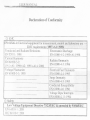
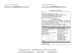
Declaration of Conformity
@EMC
EN 61326-1: Electrical equipmentformeasurR}J1e1ff;,co~kt~
EMC re ltirements (1997+~t~,l998
Conducted and Radiated Emissions
ElectrostaticDischarge
EN 55011: J998
EN 61000-4-2: 1995+Al:1998
Current Harmonic
Radiated Immunity
EN 6] 000-3-2:
EN
61000-4-3: 1996
j 99S+A]: ]998+A2: ]998 +A14: 2000
Electrical Fast Transients
Voltage Fluctuation
EN 6]000-3-3: ]995
EN 61000-4-4: 1995
-- -- _n - - - - -- - - - -- - - n - --
- -- n -- - -n_- - -- --n -- --nn
nnnn_--_----
Surge Immunity
EN 61000-4-5: 1995
Conducted Susceptibility
EN 61000-4-6: 1996
Voltage Dips/ Interrupts
EN 61000-4-11: 1994
@ Safety
Low-VoItage Equipment Directive 73/2.~IEEC&anlt~rideg.bY93/68!E~C
EN 61010-1 : 2001
lEC 61010-] : 2001
'-'--'-'-"-1_"ViU0ll-VUllUllVYVLa"C>UllLl
USER MANUAL
USER MANUAL
SECTION
1. INTRODUCTION
2. SPECIFICATIONS..
2-1 GeneraL
PAGE
1
...
""""'"
2
2
2-2 Operation lVIode
2-3 Constant Voltage Operation
2
2
2-4 Constant Current Operation
2-5 Tracking Mode
2-6lVleter
""""""'"
3
3
3
2-7 Insulation
3
3. TliEORY OF OPERATION
4. PANEL CONTROLS AND INDICATORS
4
6
4-1 Front Panel
4-2 Rear Panel
8
10
5. OPERATION INSTRUCTION
5-1 Precaution
"""""""'"
5-2 Setting Current Limit
11
11
11
5-3 Constant Voltage/ Constant Current Characteristic
5-4 Operation lVlode
6. 1VIAINTENANCE
12
13
18
6-1 Fuse Replacement
18
6..2Line Voltage Conversion
6-3 Adjustnlents
18
19
6-4 Cleaning
;.
6-5. Service, Repair and Calibration
"
21
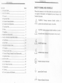
SAFETY TERMS AND SYMBOLS
Please take a imoment to review these safety terms and symbols which
may appear in this manual or on Equipment to prevent damage to the
Function Generators.
Jj\
ill
&
&
&
(f)
that!could result in damage to this product or other property.
DANGERH;gh Voltage
ATTENTIONrefer to Manual
Protective Conductor Terminal
(ground) Earth Terminal
rh
or
CAUTION. Caution statements identify conditions or practices
-L
, 21
11
WA~NING. Warning statements identify condition
practices that could result in injury or loss of life.
Frame or Chassis Terminal
'k-'k""JiHUL.d.L-'.JU.L.L
USER MANUAL
U.L
.L'.JHL.l',uU.L.LL.L
USER MANUAL
FOR UNITED KINGDOM ONLY
NOTE:
This lead/appliance
must only be wired
persons.
\VARNING: THIS APPLIANCE MUST BE EARTHED
IMPORTANT:
by competent
The wires in this lead are coloured in accordance
with the
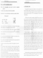
1. INTRODUCTION
The regulated DC power supply series is designed to be used in applications such as
powering operational amplifier, push-pull stages, logic circuit and definition systems
where plus and minus voltages are required to track with an insignificant error. To
represent an opera~ionconvenience, 72-7245 is two independent power supplies housed in
a single package,
following code:
Green/ Yellow: Earth
Blue:
Neutral
Brown:
Live(Phase)
E
OO
0 ~
N
L
As the colours of the wires in main leads may not correspond with the colours
marking identified in your plug/appliance, proceed as follows:
The wire which is coloured Green & Yellow must be connected to the Earth
tcnninal marked with tl1e Jetter E or by the earth symbol
@
or coloured Green
or Green & Yellow.
The wire which is coJoured Blue must be connected to the terminal which is
marked with the letter N or coloured Blue or Black.
The wire which is coloured Brown must be connected to the terminal marked with
the letter L or P or coloured Brown or Red.
If in doubt, consult the instructions provided with the equipment or contact the
supplier.
This cable/appliance should be protected by a suitably rated and approved HBC
mains fuse: refer to the rating information on the equipment and/or user
instructions for details. As a guide, cable of O.75mm2 should be protected by a
3Aor SA fuse. Larger conductors would normally require 13A types, depending
on the connection method used.
Any moulded mains connector that requires removal/replacement
must be
destroyed by removal of any fuse & fuse carrier and disposed of immediately, as a
plug with bared wires is hazardous if a engaged in live socket. Any re-wiring must
be carried out in accordance with the information detailed on this label.
72- 7245 consists of two identical, independent, adjustable DC power supplies. A front
panel switch selects one of three operation modes of independent, series and parallel. In tbe
independent mode', the output voltage and current of each supply are controlled separately,
and each supply i~ isolated up to 300V from output to chassis or output to output. In the
tracking mode, both outputs are automatically connected in series or parallel, and the
controls of the left supply adjust the magnitudes of both the positive and negative output
voltages. Because! the outputs are connected in a tracking configuration, any internal
disturbance in the! master supply (such as drift or ripple) wiJl cause an equal percentage
change in the outp'uts of both the supplies.
Both power. supplies are completely
transistorized,
well-regulated,
constant
voltage/constant cblTent supplies that will provide full rated output voltage at th~ maximum
output current or ckn be continuously adjusted throughout the output range. The front panel
current controls can be used to establish the output current limit (overload or short circuit)
.when
the supply is used as a constant voltage source (independent or tracking modes) and
the voltage controls can be used to establish the voltage limit (ceiling) when the supply is
used as a constant current source (independent mode only). The supply will automatically
cross over from constant voltage to con~tant current operation (current limited operation in
the tracking mode). Each power supply (CHI-CH2) has its own front panel meter that can
measure output voltage or current~ One power supply may be used as a CHI supply
controlling, and CH2 may be used for furnishing various voltages or currents for a system.
When operated with the front panel mode switch in the tracking position, the instrument is
automatically internally connected in auto-tracking configuration.
'
For audio production line, the continuous or dynamic load can be internally selected.
When the connector (nIl &1309)is connected to "ON" position the unit is suitable for
audio power Amplifier application (Normal setting to "OFF" position).
72-7245 MULTI-OUTPUT
POWER SUPPLY
72-7245 MULTI-OUTPUT POWER SUPPLY
USER MANUAL
USER MANUAL
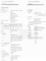
2. SPECIFICATIONS
2-1. General
Main Supply (switch selectable)
Operation Environment
Storage Tcmperature & Humidity
Accessories
Table 2-] :
TRACKING
Independent Series Para
GOY 30Y
0-30Yx2
72-7245
0-3Ax2
3A
6A
MODEL
Dinwnsions
Weight (kg)
2-2. Operation Mode
(1) Independent
(2) Series
(3)'ParaJIeI
2-3. Constant Voltage Operation
(1) Output voltage range
(2) Regulation
(3)
(4)
(5)
2-4.
(J)
(2)
Recovery time
Ripple & Noise
Temperature coefficient
Constant Current Operation
Output current range
Regulation
(3) Ripple current
: IOOVI120VI220V:I: 1O%(230V +10%--6%)
:Indoor use.
SO/60Hz.
'
Altitude up to 2000m.
Ambient temperature DoCto 40'C.
Relative humidity 80% (maximum).
Installation category II.
Pollution degree 2.
: -10°C to 70°C.70% (maximum).
: Operation Manual xl.
REPLACED FUSE TYPE RATES INPUT
TEST LEAD
IOOV/120Y 220V/230Y WATTS YA GTL- 104 GTL-I05
T6A
T3A
450
2
0
350
250Y
250Y
: 255(W) xI45(H) x265(D) m/m
: 7.0 kg.
; Two independent outputs and
Output from 0 to rating volts and 0 to rating amperes.
: Output from 0 to rating volts at rating amperes each.
: Output from 0 to double rating volts at rating amperes.
: Output from 0 to double rating amperes at rating
volts.
: 0 to rating voltage continuously adjustable.
: Line regulation;;?;O.OI% + 3mV.
; Load regulation;;?;O.OI %+3mV(rating eurrent;;?;3A).
: Load regulation;;?;0.02%+5mV (rating current>3A).
:;;?;100/.1 s (50% load change, minimum load O.SA ).
:;:;>ImVrms (5Hz-lMHz).
: ;;?;300ppmtC .
: 0 to rating current continuously adjustable.
: Line regulation;;?; 0.2% + 3mA.
: Load regulation;;?;0.2% +3mA.
:;;?;3mArms.
2.5. Tracing qperation
(1) Parallel Operation
Regulatio~
: Line regulation;;?;O.OI % + 3mV.
: Load regulation;;?;O.OI %+3mV (rating current;;?;3A).
;;?;0.02%+5mV (rating current >3A).
(2) Series OP9ration
Regulation
: Line regulation;;?; 0.01 %+5mV.
: Load regulation;;?;300mV.
A. Positive! and Negative supply (Fig 5-4) CH2 tracking error ;;?;0.5%+ IOIDV of t
CHI (No load, with load add load regulation;;?;300mV)
B. Single s)lpply (Fig. 5-3)
2-6. Meter'
A. Display'A
DisplayV
B. Accuracy
: 3 digits panel meterx2 (OS' Red LED display).
; 3 digits panel meter x 2 (OS' Green LED display).
:OUT ON:t(0.5% of rdg + 2 digits)
C. Voltmeter
D. Ammeter
: 99.9V of full scale.
: 9.99A of full scale.
2-7. Insulation
Between chassis and output tenninal ; 20M Q or above (DC SOOV).
Between chassis and AC cord:
30MQ or above (DC 500V).
USER MANUAL
USER MANUAL
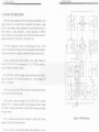
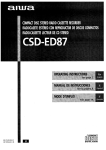
3. THEORY OF OPERATION
The power supply consists of an AC input circuit and transformer; a bias
supply consisting of an rectifier, filter, pre-regulator and reference voltage
source; a main regulator circuit consisting of the main rectifier and filter, a
series regulator, a current comparator, a voltage comparator, a reference
voltage ampJifier and a relay control circuit. The circuit element consists of
integrated circuit UlOl, UlOl, UI03, UlO4, UlOS, UlOS.
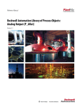
The circuit arrangement is shown as block diagram in Fig. 3-1. The
circuitl;Y is discussed with reference to the block diagram function description.
Single phase input power is applied to transformer through the input circuit.
::D
:::! C
"10a
::D
IT1
"
c.- .- IT1
CS;--i:D
w:;~~
fTl rrl C1
::D
IT1
'1
a
:::! C
c: -u 0.::D ...,
<:;;S5::D
..., en
a fTl
:JJ
Auxiliary rectifier D1O21-lO24 provides a bias voltage, filtered by
capacitor C1O3, ClO4 for the preregulator. VIOl, U1O8 that provides a
regulator voltage for elements of action.
n
On
::Ie
C:":JJ
-'::D :D
<S>:JJfTl
<J1::D Z
a-1...,
:JJ
C
(f1 a
co.-C...,:D
IS> :D ::D
NnGlZ
fTl fTl
cc
H1ffi
<S>oen
OO-::D
<S>...,
" IT1
::D
::I
'" (S)..., "Tl Z
~
~
fTl-
:x:>jj
U1O2 provides a reference voltage for UlO3, UlO5.U1O3 is a inverter
a111plifier.U1O4
is a comparator amplifier which compares reference voltage
3J1dfeedback voltage, and then delivers to Q1O3,QlO4, which then calibrates
the output voltage.
Q1l3 is activated when the unit is overload. It controls QlO3 CUITent
magnitude which limits the output current.
The
-,
. relay control circuit provides limited power dissipation in series
r::D
n
"z
C
...,
"Tl
".,'g
~~:;'J~
C»-,--
UIOS acts as a current limiter. When cunent is over predetermined rating it
is activated and decreases the current.
7;='-
x
CS; ;;;
-" :D
The main rectifier, a full wave bridge rectifier provides the power which is
filtered by capacitor, C1O2I and then regulated via a series regulator and
delivel'Sto the output.
rrl C
nn-i"'--(s)fTl-IJ
<:;;::Djj
<S>
W ,
I
".:DIJ
'" "Tl'J 2:S
-"
- "-
.0
(S)
::D
fTl
'1
fTl
fTl
n
fTl
O\P
Figure 3-1 Block Diagram
--~~
72-7245 MULTI-OUTPUT POWER SUPPLY
-- _~"~H~~"~'
USER MANUAL
USER MANUAL
25
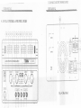
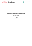
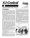
4. PANEL CONTROLS AND INDICA TORS
0
0
r-:ER.NO
"'-
~H"LM'
r-:APASS .
CE
0
~~,
~~
"-'I
L:: Cl:!1--.:U
&
Fig. 4-2 Rear Panel
0 0
&.
[[j[)u-
r;
-~
IE Iii I ~I~
~~
0 0 [O[]-o-u
@
"'""'00
I~ ~
0
0
.1~
i
USER MANUAL
USER MANUAL
+-1. Front Panel
(I)
Power switch
: ON/OFF the power input.
(2) Meter V
: Indicated the CHI output voltage.
(3) Meter A
: Indicates the CHI output current.
(4) Meter V
: Indicates the CH2 output voltage.
(5) Meter A
: Indicates the CH2 output current.
16) Voltage Control
: Adjust the output voltage of the CHI supply, and as the
adjustment control for the maximum output voltage of the
CH2 supply when either parallel or series tracking operation.
(7) Current Control
: Adjust the output current of the CHI supply, and as the
adjustment control for the maximum output current of the
CH2 supply when either parallel or series tracking operation.
(8) Voltage Control
: Adjust the output voltage of the CH2 supply when in
independent operation.
(9) Current Control
: Adjust the output current of the CH2 supply.
(10) CV&CC Indicator
: The CV light (green light) is on when the CHI supply is in the
constant voltage operation, or when both the CHI and CH2
supplies are in the constant voltage operation in either series or
parallel tracking mode.
The CC light (red light) is on when the CHI supply is in the
constant current operation.
(II) CV&CC Indicator
: The CV light (green light) is on when the CH2 supply is in the
constantvoltageoperation.
(12) Output Indicator
.
The CC light (red light) is on when the CH2 supply is in the
constant current operation or in parallel tracking mode.
: Switch the light on.
(13) + output ter{llinal
: Positive polarity output terminal for the CHI supply.
(14) - output terJ11inal
!
: Negative polarity output terminal for the CHI supply.
(15) GND terminal
: Earth and chassis ground.
(16) + output terminal
: Positive polarity output terminal for the CH2 supply.
(17) - output terminal
: Negative polarity output terminal for the CH2 supply.
(18) Output switches
: ON/OFF the output.
(19) TRACKING
& Mode Switch
Two push-button switches that select Independent mode, series
tracking mode, or parallel tracking mode as follows:
(20)
.
a. When both switches are disengaged (Ollt), the unit is in the Independent mode and
the CHI and CH2 power supplies are completely independent from each other.
b. When the left switch is engaged (in) and the right switch is disengaged (out), the
unit is in the Tracking series mode, maximum voltage of both supplies is set using
the CHI VOLTAGE controls (voltage at output terminals of the CH2 supply
tracks the voltage at the output terminals of the CHI SUPPLY). Also, in this mode
of operation, the positive terminal (Red) of the CH2 supply is connected to thc
negative terminal (Black) of the CHI supply to allow the two supplies to be used
as a 0 to double rating voltage supply.
c. When both switches are engaged (in), the unit is in the Tracking Parallel mode, the
CHI and CH2 supplies are wired together in parallel and both the maximum
current and voltage are set using the CHI controls. The CHI and CH2 output can
be used as two individual (but tracking) power supplies or just the CH I output can
be used as a 0 to rating voltage supply with a 0 to double rating current capability.
IL-IL'D
lY1ULll-VU
lYU
1 YVVYtK
.:>UYYLr
USER MANUAL
I L- / L'+:J1VlULll-VU
lYU 1 YVVYtK .:>UYYL r
USER MANUAL
5. OPERATION INSTRUCTION
4-2. Rear Panel
5-1. Precaution
(21) Fuse holder
(1) AC inp*
AC inp~t should be within the range of line voltage
+ 10%--6%) SO/60Hz.
(22) Power socket
(23) AC selects switch:
(24) HI-LO switch
(25) Cooling Fan
Selects to permit operation from 100, 120,220 or 230VAC,
SO/60Hzline voltage by using (24) HI-LO switch.
: HI position selects high voltage range (120, 230V AC inputs),
LO position selects low voltage range (100, 220V AC inputs).
: Ventilates the hot air out, to prevent output stage from thermo
shock, and improves the temperature coefficient.
,
WANING.
:!:lO% (230V
To avoid electrical shock, the power cord protective
;j\
grounding conductor must be connected to ground.
AVERTISSr Pour evitef;lesq6p~sel~ctriques, Ie fil de terre du
~ordon sectetIr,doirlrnperati;vemeiit~trerelie
it Ia terre.
(2) Installation
Avoid using the supply in a place where ambient temperature exceeds 40°C.
The heat sink located at the rear of the supply must have sufficient air space
for radiation.
ill
&
CAUTION. To avoid damaging the power supply, don't use
it in a place where ambient temperature exceeds 40°C.
(3) Output voltage overshoot
Voltage ,between output terminals never exceeds the preset value when the
power is turned on or off.
5-2. Setting Current Limit
(1) Determine the maximum safe current for the device to be powered.
(2) Temporarily short the (+) and (-) terminals of the power supply together with a test
lead.
(3) Rotate the VOLTAGE control away from zero sufficiently for the CC indicator to
light.
(4) Set the meter selection switch to "A" position to select the current metering mode.
(5) Adjust the CURRENT control for the desired current limit. Read the current value on
the Ammeter.
(6) The cun:ent limit (overload protection) has now been preset. Do not change the
CURREI'F control setting after this step.
(7) Remove the short between the (+) and (-) terminals and hook up for constant voltage
operation,
,~
USER MANUAL
'~'~H~~~~~~~~~~~~~,,~n~~~.~~
USER MANUAL
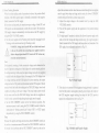
5-3. Constant Voltage/Constant Current Characteristics
The working characteristic of these series Power Supplies is called a constant
voltage/constant current automatic crossover type. This permits continuous
transition from constant current to constant voltage modes in response to the
load change. The intersection of constant voltage and constant current modes
is calJed the crossover point. Fig. 5-1 shows the relationship between this
crossover point and the load. .
For example, if the load is such that the power supply is operating in the
constant voltage mode, a regulated output voltage is provided. The output
voltage remains constant as the load increases, up until the point where the
present current limit is reached. At that point, the output current becomes
constant and the output voltage drops in proportion to further increases in
load. The point is indicated by the front panel LED indicators. The crossover
point is reached when the CV indicator goes off and the CC indicator comes
on.
crossover ~oint where the power supply goes into the constant voltage mode.
5-4. Operation Mode
(1) IndependentiOperation
The "CHI" and "CHT' supplies each provide a 0 to rating volts output at up to
rating amps. This procedure covers the use of the CHI and CH2 supplies only
when they are used independently from each other. When used in the
independent pperating mode, the operation controls of the two power supplies
are completely independent and either supply can be used individually or both
can be used simultaneously.
A. Disenga&e both Tracking mode switches (both switches out) so that the
power supply is in the independent operating mode.
B. Adjust "Voltage" control and "Current control to the desired output
voltage and current.
~
C. Turn off the power supply and the equipment
VO MAX
10 MAX
to be powered during
hook-up. !
D. Connect the positive polarity of the device being powered to the red (+)
CROSSOVER
i
CONSTANT
UOL TRGE
OUTPUT
VOLTAGE
POINT
RRNGE
terminal of the power supply.
E. Connect the negative polarity of the device being powered to the black (-)
terminal of the power supply.
OUT OUT
F. Fig.5-2 illustrates the connection procedure.
CURRENT
+
Fig. 5-1 Constant Voltage/Constant
Current
OJ!
Characteristic
Similarly, crossover from the constant current to the constant voltage mode
automatically occurs from a decrease in load. A good example of this would
be seen when charging a 12 volt battery. Initially, the open circuit voltage of
the power supply may be preset for 13.8 volts. A low battery will place a
heavy load on the supply and it will operate in the constant current mode,
which may be adjusted for a 1 amp charging rate. As the battery becomes
charged, and its voltage approaches 13.8 volts, its load decreases to the point
where it no longer demands the full 1 amp charging rate. This is the
,
Power
t;
Supply
Fig. 5-2 Independent Operation
USER MANUAL
(2) Series Tracking Operation
When the series tracking mode of operation is selected, the position (Red)
USER MANUAL
terminal of the CH2 supply output is internally connected to the negative
adjust the ma,ximum current value. Because current through the two supplies
must be equ~l when they are being used in series, the lowest CURRENT
control setting will set the maximum output cunent.
(black) terminal of the CHI supply.
In the series tracking mode, the maximum output voltage of both CHI and
C. Adjust the output voltage to the desired level by using the CHI
VOLTAGE controls.
CH2 supplies can be simultaneously varied with one control. The maximum
D. Turn off Ithe power supply and the equipment to be powered during
CH2 supply voltage is automatically set to the same as the CHI supply by
using the CH 1 VOLTAGE controls.
A. Set the power supplies to the Tracking series mode by engaging the left
Tracking switch and release the right Tracking switch.
WARNING. Voltage more than 60V DC has a lethal shock hazard
to the user. Be careful when connecting power supplies in series to
&
hook-up.:
E. If "single supply" operation is desired, this allows the power supply to be
used as twice the voltage and rating current simply by using the negative
(black) te~minal of the CH2 supply and the positive (red) terminal of the
CHI supply, the configuration as shown in Fig. 5-3.
achieve voltages higher than 60V DC total or 60V DC between any
connection and earth ground.
Note:
Simultaneously metering of both current and voltage can be obtained in the
mode of operation setting one of the displays for current metering and one
for voltage metering. In this case, the output voltage (across the two supplies)
is actually double the displayed value. For example, if the CHI display is set
for voltage metering and the CH2 display for current metering, the output
voltage across the CHI positive (red) terminal and the CH2 negative (black)
terminal would be double the reading on the CHI LED Display (since both
supplies are putting out the same voltage). The actual output current would
be the value read from the CH2 LED Display (since the two supplies are
wired in series, current flowing through each supply must be equal).
13.Set the CH2 CURRENT control to the full clockwise position. The
maximum current is set by using the CHI CURREN control. Follow the
instructions for "Setting current Limit" (select "CHI" or "CH2" supply
independently by using the CHI CURRENT control).
Note:
Because the supplies are being used in series, either CURRENT control can
be used to set maximum current. If desired, the CHI CURRENT control can
be rotated fuJly clockwise and the CH2 CURRENT control can be used to
Power
Supply
Fig. 5-3 Single Supply
F. If the chassis or common of the equipment being powered is separated
from both ,the positive and negative polarity power inputs, the outpLltof
the CH2 (negative) supply tracking the output of the CHI (positive)
supply, the configuration as shown in Fig. 5-4.
Fig. 5-4 Positive and Negative Supply
IL-IL'!-J
lVlULl.l-UUU'Ul YUwtKC:iUYYLY
USER MANUAL
USER MANUAL
(3) Parallel Tracking Operation
[11tile parallel tracking mode of operation, both supplies are strapped
together (in parallel). This allows for a rating voltage supply with a double
rating current capability, Only the CHI output terminals are used for parallel
tracking operation. In the parallel tracking mode, the CH2 supply output
voltage and current track the CHI supply output voltage and current.
A, Se! the power supplies to the Tracking Pm'allel mode by engaging both
Tracking switches,
B.Output voltage will now be read from the CHI VOLTAGE display.
Output cun'ent is exactly double the value read from the CHI CURRENT
display (because each supply is providing the same amount of current),
c.Because both voltage and CUlTentof the CH2 supply track the CHI supply,
the maximum current and voltage are set by using the CHI controls, Using
the CH I supply output jacks, follow the instructions for "Setting Current
Limit" (5-2 Section). Remember that the actual current output at the CHI
~upply output jack is double the reading on the CH2 indicator meter.
D.Adjust the output voltage to the desired level by using the CHI
VOLTAGE controls.
;
E.Turn off the power supply and the equipment to be powered during
hook-up,
F. Connect the positive polarity of the device being powered to the red (+)
terminal of the CH I power supply.
G. Connect the negative polarity of the device being powered to the black (-)
terminal of the CHI power supply. The configuration is shown as Fig.
5-5:
alJ
Power
11J2
Supply
Fig. 5.5 Parallel Tracking Operation
(4) Dynamic Load Operation & Application
A. When sdlect to dynamic load position, the max peak current is at 1,7
times rating current. The features are only applied for audio circuit of
amplifier and audio production lines. Change the position of wafer J IJ 1
of CHl and 1309 of CH2 from "OFF" to "ON". Please refer to Fig.6-1
Adjustment Location.
B: For other application and testing (Safety or CEoetc.), must set the wafer
at "OFF" position
(5) Output ON/OFF Action
The output ON/OFF action is controlJed with a single control, the output
switchis p~shedon, a highsingleoutputis on and outputLEDis on, while .
the output switch is pushed off, or tracking switch is pressed, output wi11
disable.
&
CAUTION: The output terminals
are for use only with the
equipment whicl1l1as no accessible live parts. The output terminals
should not be connected to any hazardous live parts.
(6) Fan Control
I) The fali of the power supply will not work upon power on until the
temperature of the heat sink rises up to 32°C :t5°C after adding load to
output terminal. The more the temperature of the heat sink rises, the
more the rol1ing speed of the fan gets fast. The fastest rolling speed is
when the temperature reaches to 70°C.
'
2)
To avoid damaging the power supply, if the fan fails to work when the
temperature reached to the appropriate value, turn off the instrument
and check the cause.
Tl-T14S
~_.
llSJ3R MANUAL
1 POWbK
:SUl'PL Y
USER MANUAL
6. MAINTENANCE
WARNING
The following instructions are for use by qualified personnel only. To avoid
electrical shock, do no perform any servicing other than the operation instruction
of the manual unless you are qualified to do so.
6.1. Fuse Replacement
If the fuse blows, the CV or CC indicators will not light and the power supply
will not operate. The fuse should not normally open unless a problem has
developed in the unit. Try to determine and correct the cause of the blown
fuse, then replace only with a fuse of the correct rating and type. The fuse is
located on.the rear panel (see Fig.4-2 & Table 2-1).
WARNING: For continued fire protection, replace fuse only
with 250V fuse of the specified type and rating, and disconnect
power cord before replacing fuse.
AVERTISS: Pour une protection contre les risques d'incendie,
remplacer Ie fusible eXcll1sivement par un modele aUK
caracteristiques equivalentes.
6-2. Line Voltage Conversion
The primary winding of the power transformer is tapped to permit operation
from] 00, 120, 22Q,or 230VAC, SO/60Hzline voltage. Conversion from one
line voltage to another is done by change AC selects switch as shown in Fig.
4-2.
The rear panel identifies the line voltage to which the unit was factory set. To
convert to a different line voltage, perform the following procedure:
(1) Make sure the power cord is unplugged.
(2) Change the AC selects switch to the desired line voltage position.
(3) A change in line voltage may also require a corresponding change of fuse
value. Install the correct fuse value as listed on rear panel.
&
MULTl-UUH'U
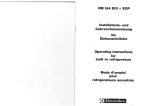
6-3. Adjustments
This unit was ,accuratelyadjusted at the factory before shipment. Readjustment
is recommended only if repairs have been made in a circuit affecting
adjustment a6curacy or if you have a reason to believe the unit is out of
adjustment. The recommended calibration device is a multimeter with an
accuracy of :tp.1% DCV or better.
If readjustment is required, use the following procedure. The location of the
adjustments is shown in Fig. 6-1.
(1) Independent Adjustment
.A.Disengage both Tracking mode switches (both switches out) so that the
power supply is in the independent operating mode.
B. Connett a 4-1/2 digital multimeter with an accuracy of :to.1% DCV to
measure the DC voltage at the output terminals of the CHI (CH2)
supplY;.
-
C. Set the CHI (CH2) VOLTAGE control to maximum (fully clockwise).
D. Adjust'trimmer potentiometer (VRlOI CHI,VR30l CH2) on the circuit
board (located on the right side of the supply) for a reading as close to
rating voltage x1.0S (on the multimeter) as possible.
E. Set output on by adjusting the trimmer potentiometer (VR80l CH2,
VR201 CHI) from the CHI (CH2) voltage indicator circuit board
(located on the meter or A/D converter board) for a reading of rate
voltage x1.0S on the CHI (CH2).
F. Conner.;tthe external multimeter across the CHI (CH2) SUPPLY output
terminals to read the output current (so that the meter causes a short
circuit! across the terminals) and adjust the CHI (CH2) CURRENT
control so that rating amps is read on the multimeter.
G. Set output on by adjusting the trimmer potentiometer (VR901 CH2,
VR701 CHI) so that the CHl(CH2) meter~alsoreads rating amps.
H. Rotate the CHI (CH2) current control fully clockwise (maximum).
1. Adjust VR103 on the CHI (VR303 CH2)supply circuit board (located
on the tight side of the supply) to obtain an output current of rating amps
x1.0S (read on the meter or LED display).
(2) Series Tracking Adjustment
A. Set the supply to Tracking series mode by engaging the left Tracking
. switch and releasing the right tracking switch.
B.Set the CH2 CURRENT control to midrange and set the CHI supply
voltage controls to minimum (fully counterclockwise).
72-7245 MULTI-OUTPUT POWER SUPPLY
USER MANUAL
USER MANUAL
c.COlllJect the multimeter to the CHI SUPPLY outputs and measure the
voltage.
D.Disconnect the multimeter from the CHI supply outputs and connect it
across the CH2 supply outputs.
E. Adjust trimmer potentiometer VR306 on the circuit board (located on the
right side of the supply) to obtain the exact same reading for the CH2
supply output as was preset at the CHI supply output (e.g., if the
minimum CHI supply output voltage is -IO.OOmV adjust VR306 to
obtain an output voltage as close to -IO.OOmV at the CH2 supply as
possible).
F. Set the CH2 CURRENT control to midrange and set the CHI supply
voltage controls to maximum (fully clockwise).
G. Connect the multi meter to the CH I supply outputs and measure the
voltage.
H. Disconnect the multi meter from the CHIsupply
across the CH2 supply outputs.
outputs and connect it
panel circuit board, VOLTAGE/CURRENT CONTROL potentiometer
board) until the voltage read from the multimeter is the same as it was
across the CH I output terminals. Return the multimeter to the CHI output
tennina]s and verify that the output voltage is identical. If not, repeat this
step.
(3) Parallel Tracking Adjustment
A. Disengage both Tracking mode switches (both switches out) so that the
power supply is in the independent operating mode.
U. Set the CHJ supply VOLTAGE and CURRENT controJs to minimum
(fully counterclockwise).
C. Connect the multimeter across the CH I supply output terminals and
measure the output current.
D. Set the CHI supply VOLTAGE contraJ to midrange and adjust the
control
to oht~in
~n OIltnllt
(,llrrpnt
6-4. Cleaning
To clean the power supply, use a soft cloth dampened in a solution of mild
detergent and water. Do not spray cleaner directly onto the instrument, since it
may leak into the cabinet and cause damage. Do not use chemicals containing
benzine, bertzene, toluene, xylene, acetone, or similar solvents. Do not use
abrasive cleaners on any portion of the instrument.
6-5. Service, Repair and Calibration
For Service, ,Repair
and calibration please contact your local Tenma distributor or go to
I
r. Set output on by adjusting VR50 I (located at the left of the lower front
.CURRENT
E. Engaged both Tracking mode switches (both switches in), so that the
power supply is in the parallel operating mode.
F. Set th~ CH2 supply CURRENT control to maximum (fuJly clockwise)
and set the VOLTAGE control to midrange.
G. Set output on by adjusting the trimmer potentiometer VR502 on the
circuit ~oard (located on the right side of the supply) to obtain an output
current!of double rating amps on the multimeter.
nf r<1t;ncr "mm
(r"",d
nn
httR://www.tenma.com
,
'
---
-------- -----
------------
-----
-----
---------- -----
-
----------- ------------I
~
, .
tj
~~
!
r:;;j
~
u
~EJi
~
~EJii
~
EJ 1
i
: -i.~!
:
!
Ii
t
!
B
$
.
"""
i
i, -1.
H
-
,
~EJ
,
i,~
[] ~-
EJ
fI<EJ
i-
~EJ [l
~tJ
~
<J::
;:J
Z
<J::
~
~
ll..)
CI)
;:J
Ii
i
:
C]
r:J
Q
CJ~
mc:J [2J
CJCJuCJi
i,
'
'
1
§
:,::
1:'::1
u
0
,.J
c
OJ
a
...
on
::I
.,
"'0,
<
,...,
,c
on
~