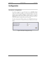
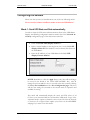
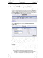
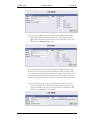
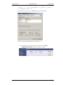
1
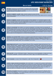
LED-Matrix Display
LED2 Matrix Display
User Manual
Version 2.0
Generex GmbH
LED-Matrix Display
Sep 08, 2006
www.generex.de
Revision
-001
History
First Release.
Date
09/2006
Legal Information
This documentation as well as the software and hardware described in it is
furnished under license and may only be used or copied in accordance with the
terms of the license. The information in this document is furnished for
informational use only, is subject to change without notice, and should not be
construed as a commitment by Generex GmbH. Generex GmbH assumes no
responsibility or liability for any errors or inaccuracies that may appear in this
document or any software that may be provided in association with this
document. Except as permitted by such license, no part of this document may
be reproduced, stored in a retrieval system, or transmitted in any form or by
any means without the express written consent of Generex GmbH.
Information in this document is provided in connection with Generex GmbH
products. No license, express or implied, by estoppel or otherwise, to any
intellectual property rights is granted by this document. Except as provided in
Generex GmbH's Terms and Conditions of Sale or License Agreement for
such products, Generex GmbH assumes no liability whatsoever, and Generex
GmbH disclaims any express or implied warranty, relating to sale and/or use
of Generex GmbH products including liability or warranties relating to fitness
for a particular purpose, merchantability, or infringement of any patent,
copyright or other intellectual property right. Generex GmbH products are not
intended for use in medical, life saving, or life sustaining applications. Generex
GmbH may make changes to specifications and product descriptions at any
time, without notice.
Third-party marks and brands are the property of their respective owners.
Copyright © 2006 Generex GmbH. All Rights Reserved.
LED2 User Manual
2
Generex GmbH
LED-Matrix Display
Sep 08, 2006
Contents
Introduction
Overview ...................................................................................................4
Display ......................................................................................................4
Configuration
LED-Matrix Configuration .......................................................................5
Configuring the Senders.........................................................................6
Mode 1: Send UPS State and Data automatically .....................................6
Mode 2: Send RCCMD messages from UPS Events.................................7
LED2 User Manual
iii
Generex GmbH
LED-Matrix Display
Sep 08, 2006
Introduction
Overview
The LED-Matrix Display is based on the CS121 Web Adapter. Please refer
to the CS121 user manual for an explanation regarding the configuration of
the network settings, event handling etc. The CS121 user manual is coming
with the LED MATRIX or can be downloaded from GENEREX Website,
Download Area, Documentation.
This document describes the special features that are unique to the LED
Matrix that do not pertain to the standard CS121 and provides instructions
on how to operate the LED Matrix.
The LED-Matrix Display is a remote display unit for relaying either UPS
status and values or customized RCCMD messages that can be operated
via the Ethernet. Any CS121 Web Adapter and other RCCMD 2
compatible products can send text messages or environmental data values
to the LED-Matrix and can add sounding alarms for warnings that require
immediate attention (optional, only with buzzer connected to AUX port).
Display
Depending on the length of the LED-Matrix-Display anywhere between 4
and 30 characters can be shown at once. If the intended message is too
long for the number of displayable characters, the message is scrolled
automatically through the display screen.
Figure: LED-Matrix Display, short version
Messages that are to be shown via the display of the LED-Matrix can be either
input automatically by CS121 devices in the network or through the RCCMD
sending mechanisms of other network enabled devices.
LED2 User Manual
4
Generex GmbH
LED-Matrix Display
Sep 08, 2006
Configuration
LED-Matrix Configuration
The default configuration of the LED-Matrix has the RCCMD Listener
enabled and its Port set to 6002. It is strongly recommended to keep these
settings. All other configuration parameters should be adjusted to the local
network settings using either TELNET, a Terminal program, or using the
simplest method, a Web browser. Simply activate a route to the default IP
10.10.10.10. Steps for the initial setup are covered in the Quickstart instructions
of the CS121 which is contained in the CS121 user manual.
All other settings and possibilities relating to the SNMP-WEB interface are
explained in the CS121 user manual that has been included with the LEDMatrix.
Figure: LED-Matrix Configuration Page
LED2 User Manual
5
Generex GmbH
LED-Matrix Display
Sep 08, 2006
Configuring the Senders
Please note that you have to decide between one of the two following modes.
Do not connect Senders in different modes to the same LED-Matrix!
Mode 1: Send UPS State and Data automatically
In order to show the UPS status and measurement values in the LED-MatrixDisplay, the following configuration must be made in the CS121 Network &
Security configuration page of the web browser interface:
•
Check the Enable LED Display Sender box
•
Enter a unique Number in the range from 0 to 9 in the field LED
Display Sender ID. This Number is used to identify this device on
the LED-Matrix.
•
Enter the IP Address of your LED-Matrix in the field LED
Display Listener Address“.
NOTE: Remember to click the Apply button; only then will the changes
be stored in the RAM of the CS121/LED MATRIX. Also, after all
changes have been made be sure to save and restart the system by clicking
the Save, Exit and Reboot on the Save Configuration page. Only then
will the new settings be activated in the current mode of operation and
available for testing.
This mode will automatically display the status and UPS values of all
CS121 in your network which have activated the LED mode. Usage of the
automatic mode 1 requires a firmware version on the CS121 in the network
of Version 3.45 or higher. Please update your CS121 via the GENEREX
webpage if you want to use this mode 1.
LED2 User Manual
6
Generex GmbH
LED-Matrix Display
Sep 08, 2006
Mode 2: Send RCCMD messages from UPS Events
Example: Configuring the CS121 to send Event messages to the LED-Matrix
In order to show the Battery Autonomy Time of the UPS in the LED-MatrixDisplay for example, the following configuration must be made in the CS121
Events and Alarms configuration page of the web browser interface. Click on
the event Powerfail in the Events and Alarm overview table.
Click the Add new job button and select Send RCCMD Command to
remote client.
The parameters for this job must include the target IP Address of the LEDMatrix, and the Port 6002. NOTE! 6003 is the default port that is reserved for
all other RCCMD commands. As explained earlier, Port 6002 is the default
listening port of the LED-Matrix. In addition the desired text and display
mode of the message are to be designated.
The command line syntax is as follows:
Examples:
1. “|UPSCMD|2000|Continual-display" : This causes the text
„Continual-display“ to be shown continually without change
and without scrolling until another display command has been
received.
2. The following configuration will make the text BATT display
immediately once in accordance with the selected stereo button after
the UPS has gone into battery mode following a power outage.
LED2 User Manual
7
Generex GmbH
LED-Matrix Display
Sep 08, 2006
3. If you wish to add other text messages to be displayed in the LEDMatrix then commit the current job to the settings by pressing the
apply button and return to the Event overview and click on an event.
Then click the Add new job button.
In the example above, the settings are similar to adding a plain text, but
instead the system variable #ATIME (Battery rest time) is entered. The
stereo button time settings cause the message to appear after a delay of 30
seconds which will also then be repeated every 30 seconds. The system
variable #ATIME is the battery rest time or „Autonomy time in minutes“.
4. To send an all-clear message to cancel the alarm such as a „Power
restored“ message after a „Powerfail“ alarm, simply select the event
„Power restored“ in the event overview and enter a suitable text like
„NETZ“ or „GRID OK“ for example.
LED2 User Manual
8
Generex GmbH
LED-Matrix Display
Sep 08, 2006
NOTE: Remember to click the apply button; only then will the changes be
stored in the RAM of the CS121/LED-Matrix. Also, after all changes have
been made be sure to save and restart the system by clicking the Save, Exit
and Reboot button on the Save Configuration page. Only then will the new
settings be activated in the current mode of operation and available for testing.
Tests: After the CS121 that is connected to the UPS has been restarted and
the green LED is blinking and the web browser is indicating measurement
values, tests can be conducted by either putting the UPS directly into battery
mode or by sending test signals in the Alarm and Events section of the Web
browser interface of the CS121. Information: When conducting test using the
Web browser, trying to send system variables like „ATIME“ will only result in
sending the variable name to the LED-Matrix display.
5. ALARMBUZZER: To toggle the ALARMBUZZER in the LED
Matrix, you have to send an RCCMD EXECUTE from your CS121
sender to the IP Address of your LED MATRIX, Port 6002. The
syntax for the command is: “|AUX|3|1” to switch on, “|AUX|3|0
“ to switch off.
Buzzer ON:
Buzzer OFF:
If you use a UPSMAN software or a RCCMD commandline as sender for your
LED-Matrix, it works accordingly.
Example:
To switch the buzzer off via a RCCMD command enter:
LED2 User Manual
9
Generex GmbH
LED-Matrix Display
Sep 08, 2006
“rccmd -s -a <your LED MATRIX IP adress> -p 6002 se "EXECUTE |AUX|1|0"
To switch the buzzer on via a UPSMAN software for Windows
Please note that any command has to start with „|“.
6. You may test your buzzer using the button in the AUX &
TEMPMAN STATUS page of your CS121 sender:
LED2 User Manual
10