1
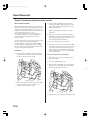
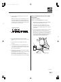
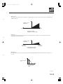
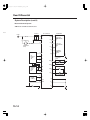
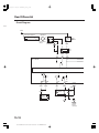
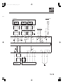
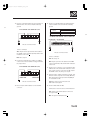
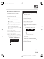
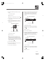
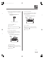
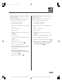
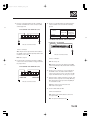
07/05/09 16:43:09 61SJC020_150_0001
Rear Differential
Rear Differential
Special Tools .................................................................
Component Location Index .........................................
General Troubleshooting Information .......................
DTC Troubleshooting Index ........................................
Symptom Troubleshooting Index ...............................
System Description ......................................................
Circuit Diagram .............................................................
DTC Troubleshooting ...................................................
Symptom Troubleshooting .........................................
Rear Differential Fluid
Inspection and Replacement ...................................
Rear Differential Function Test ....................................
Rear Differential Fluid Temperature Sensor
Replacement .............................................................
VTM-4 LOCK Switch Test/Replacement .....................
VTM-4 Control Unit Replacement ...............................
VTM-4 Relay Replacement ..........................................
Rear Differential Breather, Line, and Hose
Replacement .............................................................
Rear Differential Mount Replacement ........................
Rear Differential Removal ............................................
Backlash Inspection ......................................................
Rear Differential Installation ........................................
SJC8A000000000J1501ZCAT00
15-2
15-3
15-4
15-10
15-11
15-12
15-18
15-20
15-41
15-47
15-48
15-49
15-49
15-50
15-50
15-51
15-52
15-53
15-55
15-56
07/05/09 16:43:09 61SJC020_150_0002
Rear Differential
Special Tools
Ref. No.
Tool Number
07SAZ-001000A
07AAD-S9VA000
01
01
15-2
SJC8A000000000J1501PAAT00
Description
Backprobe Set
Driveshaft Remover
Qty
2
1
07/05/09 16:43:11 61SJC020_150_0003
Component Location Index
*01
VTM-4 LOCK
INDICATOR
VTM-4 LOCK SWITCH
Test, page 15-49
Replacement, page 15-49
VTM-4 INDICATOR
VTM-4 CONTROL UNIT
Replacement, page 15-50
REAR DIFFERENTIAL BREATHER LINE
Replacement, page 15-51
VTM-4 RELAY
Test, page 22-75
Replacement, page 15-50
REAR DIFFERENTIAL ASSEMBLY
Removal, page 15-53
Installation, page 15-56
15-3
SJC8A00E44381000000DAAT00
07/05/09 16:43:11 61SJC020_150_0004
Rear Differential
General Troubleshooting Information
VTM-4 Indicator
The VTM-4 indicator comes on under certain conditions even if the 4WD system is working normally. Here are some
examples:
• When you use high-powered wireless equipment such as a CB or Ham radio in the vehicle.
• When you keep spinning the front wheels while the vehicle is stuck in sand, mud, snow, etc.
• When the battery voltage suddenly drops below 8 volts or rises above 16 volts.
After the VTM-4 indicator comes on, it stays on until you turn the ignition switch off.
Diagnostic Trouble Code (DTC)
• The VTM-4 control unit can memorize up to seven different DTCs. The system displays the DTCs by blinking the
VTM-4 indicator. Multiple DTCs are displayed in the order they occured, beginning with the most recent.
• If the same DTC is detected more than once, the most recent DTC is written over the earlier one. Therefore, when the
same problem is detected more than once, it is memorized as a single DTC.
• The DTCs are memorized in the EEPROM (non-volatile memory). Therefore, the memorized DTCs are not cleared
when the battery is disconnected or the VTM-4 control unit is disconnected.
• If there is a problem in the central processing unit (CPU) of the VTM-4 control unit, the VTM-4 indicator comes on,
but no DTC is memorized.
Self-diagnosis
When a problem is detected by self-diagnosis, the system does the following:
•
•
•
•
Turns the VTM-4 indicator on.
Memorizes the DTC.
Stops 4WD control and puts the vehicle back in 2WD (FWD).
Reduces engine torque to suit the driving conditions when the abnormality was detected.
15-4
SJC8A00E44381000000BBAT00
07/05/09 16:43:12 61SJC020_150_0005
Initialization of the VTM-4 Control Unit
Whenever the VTM-4 control unit is replaced, it must be
initialized to make the 4WD system function.
There are two methods used to initialize the VTM-4
control unit. The recommended method is to use the
Honda Diagnostic System (HDS) with the appropriate
software plugged into the data link connector (DLC).
The other method is to initialize the VTM-4 control unit
manually.
Manual Initialization
1. Start the engine (the VTM-4 indicator comes on,
and the VTM-4 LOCK switch indicator is off).
2. Apply the brakes, and move the shift lever to either
R, 1, or 2, then push the VTM-4 LOCK switch (the
VTM-4 indicator stays on, and the VTM-4 LOCK
switch indicator is on). The 4WD system is now in
lock mode.
3. Turn the ignition switch OFF.
Initialization with the HDS
1. With the ignition switch OFF, connect the HDS to
the data link connector (DLC) (A) (located behind
the driver’s dashboard lower cover).
4. Turn the ignition switch ON (II) (the VTM-4 indicator
and the VTM-4 LOCK indicator both come on for
4 seconds, then go off). The VTM-4 control unit is
initialized.
01
*01
ON
VTM-4
INDICATOR
VTM-4 LOCK
INDICATOR
OFF
4 sec
ON
OFF
Engine VTM-4 LOCK Engine
start
switch push stop
4 sec
IG switch
ON (II)
A
2. Make sure the HDS communicates with the VTM-4
control unit. If it doesn’t go to the DLC circuit
troubleshooting (see page 11-194).
3. Turn the ignition switch ON (II), and follow the
prompts on the HDS screen.
NOTE: See the HDS user’s manual for specific
instruction.
(cont’d)
15-5
07/05/09 16:43:12 61SJC020_150_0006
Rear Differential
General Troubleshooting Information (cont’d)
How to Check for DTCs
When the VTM-4 control unit senses an abnormality in
the input or output systems, the VTM-4 indicator in the
gauge control module will usually come on, and the
malfunction indicator lamp (MIL), the D5 indicator, and/
or the VSA indicator may also come on.
There are two methods used to check for DTCs. The
recommended method is to use the HDS with the
appropriate software plugged into the data link
connector (DLC).
The other method is to connect the service check signal
(SCS) circuit with the HDS. When the data link
connector (DLC) is connected to the HDS, the VTM-4
indicator will blink the diagnostic trouble code (DTC)
when the ignition switch is turned ON (II) and the SCS
circuit is connected to body ground.
HDS Method
1. With the ignition switch OFF, connect the HDS to
the data link connector (DLC) (A) (located behind
the driver’s dashboard lower cover).
03
3. Turn the ignition switch ON (II), and follow the
prompts on the HDS to display the DTC(s) on the
screen. After determining the DTC(s), refer to the
DTC Troubleshooting.
NOTE: See the HDS user’s manual for specific
instruction.
4. If there are fuel and emissions DTCs, A/T DTCs, or
VSA DTCs at the same time, troubleshoot the fuel
and emissions DTCs first, then A/T DTCs second,
then VSA third, and then VTM-4 last.
5. After recording the DTCs, clear all DTCs.
6. Test-drive the vehicle for several minutes in 4WD
mode, and check for DTCs. If the DTC returns, refer
to the DTC Troubleshooting. If the DTC does not
return, there was an intermittent problem within
the circuit. Make sure all connectors and terminals
in the circuit are tight.
Service Check Signal Circuit (SCS) Method
1. Park the vehicle on level ground. Shift to P, then
turn off the engine.
2. Release the parking brake pedal.
3. With the ignition switch OFF, connect the HDS to
the data link connector (DLC) (A) (located behind
the driver’s dashboard lower cover).
04
A
2. Make sure the HDS communicates with the VTM-4
control unit. If it doesn’t go to the DLC circuit
troubleshooting (see page 11-194).
A
4. Short the SCS circuit to body ground with the HDS.
15-6
07/05/09 16:43:12 61SJC020_150_0007
5. Turn the ignition switch ON (II), and observe the
VTM-4 indicator.
NOTE: Codes above 10 are indicated by a series of
long and short blinks. One long blink equals 10
short blinks. Add the long and short blinks together
to determine the code. After determining the code,
refer to the DTC Troubleshooting.
How to Troubleshoot Circuits at the VTM-4
Control Unit
Special Tools Required
Backprobe set 07SAZ-001000A (two required)
1. Remove the right side kick panel (see page 20-60)
to gain access tothe VTM-4 control unit.
05
2. Inspect the circuit on the VTM-4 control unit
according to the DTC Troubleshooting using the
special tools and a digital multimeter or an analog
circuit tester.
Long blinks Short blinks
(2)
(4)
OFF
See DTC 24
3. Connect the backprobe adapters (A) to the stacking
patch cords (B), and connect the cords to the
multimeter or an analog circuit tester (C). Using the
wire insulator as a guide for the contoured-tip of
the backprobe adapter, gently slide the tip into the
connector from the wire side until it comes in
contact with the terminal end of the wires.
06
6. Record all the DTC(s), then refer to the DTC
Troubleshooting to determine the meaning of each
DTC.
7. Clear the DTCs from the VTM-4 control unit
memory.
C
8. If the MIL, D5 indicator, or the VSA indicator all
come on at the same time, troubleshoot the cause
for the MIL first, then A/T DTCs second, then VSA
third, and then VTM-4 last.
9. Test-drive the vehicle for several minutes in 4WD
mode, and check for DTCs.
If the DTC returns, refer to the DTC Troubleshooting.
If the DTC does not return, there was an
intermittent problem within the circuit. Make sure
all connectors and terminals in the circuit are tight.
A
07SAZ-001000A
B
07SAZ-001000A
(cont’d)
15-7
07/05/09 16:43:13 61SJC020_150_0008
Rear Differential
General Troubleshooting Information (cont’d)
How to Clear the VTM-4 Control Unit
Memory
There are two methods used to clear DTCs from the
VTM-4 control unit memory. The recommended
method is to use the HDS with the appropriate software
plugged into the data link connector (DLC).
The other method is to connect the service check signal
(SCS) connector with the HDS, and manually clear the
memory.
Service Check Signal Circuit (SCS) Method
1. Park the vehicle on level ground. Shift to P, then
turn off the engine.
2. Release the parking brake pedal.
3. With the ignition switch OFF, connect the HDS to
the data link connector (DLC) (A) (located behind
the driver’s dashboard lower cover).
08
HDS method
1. With the ignition switch OFF, connect the HDS to
the data link connector (DLC) (A) (located behind
the driver’s dashboard lower cover).
07
A
4. Short the SCS circuit to body ground with the HDS.
5. Turn the ignition switch ON (II).
A
2. Make sure the HDS communicates with the VTM-4
control unit. If it doesn’t go to the DLC circuit
troubleshooting (see page 11-194).
3. Turn the ignition switch ON (II), and follow the
prompts on the HDS screen to clear the DTC(s).
NOTE: See the HDS user’s manual for specific
instruction.
15-8
6. The VTM-4 indicator comes on and stays on for
4 seconds. Press and hold the VTM-4 LOCK swtich
while the VTM-4 indicator is on.
7. When the VTM-4 indicator goes off, release the
VTM-4 LOCK switch.
8. The VTM-4 indicator comes on and stays on for
4 seconds. Press and hold the VTM-4 LOCK switch
while the VTM-4 indicator is on.
07/05/09 16:43:13 61SJC020_150_0009
9. When the VTM-4 indicator goes off, release the
VTM-4 LOCK switch. The VTM-4 indicator will blink
twice quickly to confirm that the DTCs have been
cleared from the VTM-4 control unit memory.
NOTE: If the VTM-4 indicator does not blink twice
quickly, the memory has not been cleared. Turn the
ignition switch OFF, then repeat steps 5 through 9.
*02
How to End a Troubleshooting Session
(required after any troubleshooting)
1. Turn the ignition switch OFF.
2. Clear the DTCs from the VTM-4 control unit
memory.
3. Disconnect the HDS from the data link connector
(DLC).
IG switch ON (II)
IGNITION
SWITCH
PARKING BRAKE
SWITCH
PGM TESTER
CONNECT
VTM-4
INDICATOR
VTM-4 LOCK
INDICATOR
ON
OFF
ON
OFF
ON
OFF
ON
OFF
ON
OFF
4. Verify that the problem has been repaired; testdrive the vehicle for several minutes in 4WD mode.
0.3 sec
4 sec
4 sec
0.3 sec
0.3 sec
VTM-4 LOCK
VTM-4 LOCK
switch pushed
switch pushed
VTM-4 LOCK
VTM-4 LOCK
switch released switch released
10. Turn the ignition switch OFF, then disconnect the
HDS from the data link connector (DLC).
15-9
07/05/09 16:43:13 61SJC020_150_0010
Rear Differential
DTC Troubleshooting Index
DTC
21-1
22-1
23-1
24-1
26-1
VTM-4
Indicator
ON
ON
ON
ON
ON
37-1
38-1
41-1
ON
ON
ON
Detection Item
Left-front wheel sensor
Right-front wheel sensor
Left-rear wheel sensor
Right-rear wheel sensor
VSA modulator-control unit or wire
harness
Engine RPM signal circuit
CAN communication (PCM/VSA system)
Possible Cause
•
•
•
•
•
•
•
•
•
•
42-1
43-1
ON
ON
Differential oil temperature sensor
44-1
ON
VTM-4 relay
51-1
52-1
53-1
54-1
55-1
56-1
57-1
58-1
59-1
ON
ON
ON
ON
ON
ON
ON
ON
ON
Left clutch electromagnetic coil
•
•
•
•
•
•
•
•
•
Sensor is defective
Open or short in the wire harness
VTM-4 control unit is defective
VSA modulator-control unit is defective
Open or short in the wire harness from the
VTM-4 control unit to VSA modulator
VSA modulator-control unit is defective
Open or short in the wire harness
VTM-4 control unit or PCM is defective
Open or short in the wire harness from the
VTM-4 control unit to PCM/VSA
VTM-4 control unit or PCM is defective or
VSA modulator-control unit is defective
Sensor is defective
Open or short in the wire harness
VTM-4 control unit is defective
Relay is defective
Open or short in the wire harness
VTM-4 control unit is defective
Electromagnetic coil is defective
Open or short in the wire harness
VTM-4 control unit is defective
Right clutch electromagnetic coil
• Electromagnetic coil is defective
• Open or short in the wire harness
• VTM-4 control unit is defective
Right/left clutch electromagnetic coil
power supply
•
•
•
•
Low battery voltage
Fault in the charging system
VTM-4 control unit is defective
73-1
ON
MAP (manifold absolute pressure)
Fault in the PCM system/MAP (manifold
sensor or PCM
absolute pressure) sensor is defective
76-1
ON
Rear differential clutch warning system
• Sensor is defective
• Open or short in the wire harness
• VTM-4 control unit is defective
• VSA modulator-control unit is defective
77-1
ON
PCM
• PCM is defective
78-1
ON
VTM-4 control unit
• VTM-4 control unit is defective
41-2
ON
CAN communication (PCM/VSA system) • Open or short in the wire harness from
VTM-4 control unit to PCM (or VSA)
42-2
ON
Differential oil temperature sensor
• Sensor is defective
• Open or short in the wire harness
• VTM-4 control unit is defective
21-2
ON
Left-front wheel sensor
• Sensor is defective
22-2
ON
Right-front wheel sensor
• Open or short in the wire harness
23-2
ON
Left-rear wheel sensor
• VTM-4 control unit is defective
24-2
ON
Right-rear wheel sensor
• VSA modulator-control unit is defective
53-2
ON
Left or Right clutch electromagnetic coil
• Electromagnetic coil is defective
• Open or short in the wire harness
• VTM-4 control unit is defective
: DTCs are indicated by the VTM-4 indicator when the data link connector (DLC) is connected to the HDS.
15-10
SJC8A00E44381000000GAAT00
Page
(see page 15-20)
(see page 15-22)
(see page 15-24)
(see page 15-25)
(see page 15-27)
(see page 15-29)
(see page 15-30)
(see page 15-32)
(see page 15-34)
(see page 15-37)
(see page 15-37)
(see page 15-38)
(see page 15-40)
(see page 15-40)
(see page 15-27)
(see page 15-29)
(see page 15-20)
(see page 15-22)
(see page 15-32)
(see page 15-34)
07/05/09 16:43:13 61SJC020_150_0011
Symptom Troubleshooting Index
Symptom
Diagnostic Procedure
The VTM-4 indicator
comes on, but no DTCs
are stored in any system:
VTM-4, VSA, or PCM
Symptom troubleshooting (see page 15-41).
The VTM-4 indicator does
not come on
Symptom troubleshooting (see page 15-42).
The VTM-4 LOCK
indicator does not come
on when the VTM-4 LOCK
switch is pressed
Symptom troubleshooting (see page 15-43).
The VTM-4 LOCK
indicator comes on when
the ignition switch is
turned ON (II) and does
not go off
Symptom troubleshooting (see page 15-45).
The VTM-4 LOCK
indicator does not come
on for about 4 seconds
when the ignition switch
is turned ON (II)
Symptom troubleshooting (see page 15-46).
Noise and judder when
turning at full lock
1.
2.
3.
4.
Clunk noise and then a
bump when backing and
turning
Also check for
Drain and refill the rear differential with new VTM-4 fluid
(see page 15-47).
Do the Differential Function Test (see page 15-48).
Repeat steps 1 and 2.
Drain the rear differential, then install new drain plug
washers, and refill with new VTM-4 fluid (see page 15-47).
Normal clutch engagement at throttle opening
15-11
SJC8A00E44381000000HBAT01
07/05/09 16:43:14 61SJC020_150_0012
Rear Differential
System Description
This vehicle is equipped with a rear differential system called the variable torque management 4WD (VTM-4) system.
The VTM-4 control unit controls the current flowing through electromagnetic coils to engage and disengage the right
and left clutches in the rear differential assembly.
The operation of the VTM-4 system consists of the following functions:
• Vehicle acceleration torque control (VATC)
• Limited slip differential (LSD)
• Lock control
These functions automatically combine to distribute driving torque between the front and rear wheels when the
vehicle is being accelerated or when wheels are slipping. When the vehicle speed is about 18 mph (30 km/h) or below,
and the transmission is in R, 2, or 1, the system will manually engage the rear differential clutches when the VTM-4
LOCK switch is pressed. By design, in lock mode, the torque is reduced gradually at speeds above 6 mph (10 km/h) to
minimize the load on the 4WD system.
The VTM-4 control unit has a fail-safe function, a self-diagnosis function, and a provision to communicate with the
HDS.
*01
VTM-4 SYSTEM
VTM-4
LOCK
SWITCH
VTM-4
CONTROL
UNIT
Oil temperature
sensor signal
Right wheel
control current
VSA
MODULATORCONTROL UNIT
PCM
15-12
SJC8A00E44381000000CAAT00
Left wheel
control current
REAR DIFFERENTIAL
ASSEMBLY
07/05/09 16:43:14 61SJC020_150_0013
• VATC Control
The torque to be delivered to the rear wheels is calculated based on the acceleration of the vehicle calculated in the
VTM-4 control unit.
02
Amount of control
N·m (kgf·m)
0
Acceleration
Deceleration
Acceleration of vehicle
(calculation from driving torque)
• LSD Control
The torque to be delivered to the rear wheels is calculated based on the differences in speed and acceleration
between the front and rear wheels.
03
Amount of control
N·m (kgf·m)
0
Front wheel
rotation small
Front wheel
rotation large
Rotation difference between
front wheel and rear wheel
• LOCK Control
Rear differential clutch lock control is done by pushing the VTM-4 LOCK switch manually when the shift lever is in
R, 1, or 2.
04
100
Amount of control
(%)
6
Velocity of vehicle
(mph)
(cont’d)
15-13
07/05/09 16:43:14 61SJC020_150_0014
Rear Differential
System Description (cont’d)
Electronic Control System
VTM-4 Control Unit Electrical Connections
*02
VTM−4 CONTROL UNIT
VTM−4 RELAY
BATTERY
B7
A4
PWR
REAR DIFFERENTIAL
RCOH
FSR
RCOL
IGNITION SWITCH
IG1
A1
IG1
IG1 HOT in ON (II) and
START (III)
LCOH
LCOL
TOL
A9
A7
VSA
MODULATOR−
CONTROL
UNIT
A5
A3
FLP
TOH
B3
B4
RIGHT CLUTCH
ELECTROMAGNETIC
COIL
B1
B2
LEFT CLUTCH
ELECTROMAGNETIC
COIL
A13
A15
DIFFERENTIAL
OIL
TEMPERATURE
SENSOR
FRP
GAUGE CONTROL
MODULE
RLP
RRP
WARN1
A14
VTM−4 INDICATOR
WARN2
A11
POWERTRAIN
CONTROL
MODULE
(PCM)
A22
A12
B11
CANH
CANL
NEP
VTM−4LOCK SWITCH
LOCKSW
LOCKL
A8
A16
VTM−4 LOCK INDICATOR
A20
DATA LINK
CONNECTOR
A18
A16
SCS
PG
PARBRK
LG1
LG2
PARKING BRAKE SWITCH
15-14
B5
K−LINE
A10
B12
07/05/09 16:43:15 61SJC020_150_0015
VTM-4 Control Unit Inputs and Outputs
The VTM-4 control unit terminal voltage and measuring conditions for the 4WD control system are shown.
NOTE: Measure voltage with the connectors connected.
06
VTM-4 Control Unit Connector Terminal Locations
B (12P)
A (22P)
Wire side of female terminals
Terminal
number
A1
Wire color
A3
GRY/RED
RRP (Rear right
pulse)
A4
ORN/GRN
FSR (Fail-safe
relay)
Drives VTM-4 relay
A5
GRY/YEL
RLP (Rear left
pulse)
Detects left-rear wheel
sensor signal
A6
GRN/ORN
A7
LT GRN
PARBRK (Parking
brake)
FRP (Front right
pulse)
Detects parking brake
signal
Detects right-front
wheel sensor signal
A8
BRN/WHT
LOCKSW (LOCK
switch)
Detects VTM-4 LOCK
switch signal
A9
WHT/RED
FLP (Front left
pulse)
Detects left-front wheel
sensor signal
YEL
Terminal sign
(Terminal name)
IG1 (Ignition 1)
Description
Power supply for
activating the system
Detect right-rear wheel
sensor signal
Measurement
Conditions
Voltage
Ignition switch
Battery voltage
ON (II)
Turn wheel at 1
There should be 0−
rotation/second
about 5 V repeatedly.
(A digital voltmeter
reads about 2.5 V when
the wheel is turning
faster.)
Ignition switch
Battery voltage
ON (II)
Engine running
Less than 1 V
Turn wheel at 1
There should be 0−
rotation/second
about 5 V repeatedly.
(A digital voltmeter
reads about 2.5 V when
the wheel is turning
faster.)
Parking brake on
Less than 2 V
Parking brake off
Battery voltage
Turn wheel at 1
There should be 0−
rotation/second
about 5 V repeatedly.
(A digital voltmeter
reads about 2.5 V when
the wheel is turning
faster.)
Ignition switch
Less than 1 V
ON (II)
VTM-4 LOCK mode Battery voltage
Turn wheel at 1
There should be 0−
rotation/second
about 5 V repeatedly.
(A digital voltmeter
reads about 2.5 V when
the wheel is turning
faster.)
(cont’d)
15-15
07/05/09 16:43:15 61SJC020_150_0016
Rear Differential
System Description (cont’d)
VTM-4 Control Unit Inputs and Outputs
The VTM-4 control unit terminal voltage and measuring conditions for the 4WD control system are shown.
NOTE: Measure voltage with the connectors connected.
07
VTM-4 Control Unit Connector Terminal Locations
B (12P)
A (22P)
Wire side of female terminals
Terminal
number
A10
A11
Wire color
A12
BLU
BLK
WHT
Terminal sign
(Terminal name)
LG1 (Logic ground)
CANH
(CAN
communication
signal high)
NEP
(Engine revolution)
Description
Ground
CAN communication
signal
Detects engine
revolution signal
K-LINE
Communication signal
to HDS
SCS
(Service check
signal)
CANL
(CAN
communication
signal low)
Detects service check
connector signal
Ignition switch
ON (II)
Engine running at
1,000 rpm
Check at normal
temperature with
the ignition switch
ON (II)
VTM-4 indicator on
VTM-4 indicator off
Check at normal
temperature with
the ignition switch
ON (II)
VTM-4 LOCK
indicator on
VTM-4 LOCK
indicator off
Ignition switch
ON (II) (Not
connected to HDS)
SCS circuit shorted
SCS circuit opened
CAN communication
signal
Ignition switch
ON (II)
A13
BLK
TOL
(Temperature oil
low)
Detects differential oil
temperature sensor
signal
A14
RED/WHT
Drives VTM-4 indicator
A15
WHT
WARN1 (Warning
1)
TOH
(Temperature oil
high)
A16
YEL/BLK
LOCKL (Lock lamp)
Drives VTM-4 LOCK
indicator
A18
LT BLU
A20
BRN
A22
RED
15-16
Measurement
Conditions
Voltage
Less than 0.5 V
Ignition switch
About 2.5 V (pulses)
ON (II)
Power supply for
differential oil
temperature sensor
Above 8 V
5−8 V
1−3.6 V
Less than 4 V
Battery voltage
4−5 V
Less than 4 V
Battery voltage
About 9.0 V
Less than 2 V
About 5 V
About 2.5 V (pulses)
07/05/09 16:43:15 61SJC020_150_0017
Terminal
number
B1
Wire color
B2
BLK/WHT
B3
BLK/RED
Terminal sign
(Terminal name)
LCOH (Left coil
high)
Description
Drives left clutch
electromagnetic coil
(positive)
LCOL (Left coil
low)
Drives left clutch
electromagnetic coil
(negative)
BRN
RCOH (Right coil
high)
Drives right clutch
electromagnetic coil
(positive)
B4
GRN
RCOL (Right coil
low)
Drives right clutch
electromagnetic coil
(negative)
B5
B7
BLK
RED/BLU
PG (Power ground)
PWR (Power)
Ground
Power supply for
VTM-4 control unit
B11
RED/WHT
Drives VTM-4 indicator
B12
BLK
WARN2 (Warning
2)
LG2 (Logic ground)
Ground
Measurement
Conditions
Voltage
Ignition switch
Less than 1 V
ON (II)
Engine running
Less than 1 V
VTM-4 LOCK mode Above 3 V
Ignition switch
Less than 1 V
ON (II)
Engine running
Less than 1 V
VTM-4 LOCK mode Less than 1 V
Ignition switch
Less than 1 V
ON (II)
Engine running
Less than 1 V
VTM-4 LOCK mode Above 3 V
Ignition switch
Less than 1 V
ON (II)
Engine running
Less than 1 V
VTM-4 LOCK mode Less than 1 V
Less than 0.5 V
10 seconds after
Less than 3 V
ignition switch
ON (II)
Engine running
Battery voltage
VTM-4 LOCK mode Battery voltage
VTM-4 indicator on Less than 4 V
VTM-4 indicator off Battery voltage
Less than 0.5 V
15-17
07/05/09 16:43:15 61SJC020_150_0018
Rear Differential
Circuit Diagram
*90
BATTERY
UNDER−HOOD FUSE/RELAY BOX
No.22 (BAT) (120 A)
No.23 (IG) (50 A)
IGNITION SWITCH
G1
BAT
A6
IG1
IG1 HOT in ON (II) and
START (III)
No.18 (15 A)
D1
No.21 (7.5 A)
N44
UNDER−DASH
FUSE/RELAY BOX
No.4
(20 A)
BLK/YEL
YEL
A
WHT/RED
5
YEL
AUXILIALY
UNDER−HOOD
FUSE BOX
1
VTM−4
RELAY
3
2
RED/BLU
ORN/GRN
YEL
A1
A4
B7
IG1
FSR
PWR
VTM−4 CONTROL UNIT
WARN1
WARN2
LOCKH
LOCKSW
A14
B11
A16
A8
RED/WHT
RED/WHT
YEL/BLK
BRN/WHT
5
RED/WHT
TAILLIGHT
RELAY
1
3
INDICATOR
RED/BLK
LIGHT
C3
VTM−4
INDICATOR
GAUGE CONTROL MODULE
VTM−4 LOCK SWITCH
2
YEL
4
RED
A
DASH LIGHTS
BRIGHTNESS
CONTROLLER
(In the gauge
control module)
15-18
SJC8A00E44381000000EAAT00
07/05/09 16:43:16 61SJC020_150_0019
*90
REAR DIFFERENTIAL
: Shielding
LEFT CLUTCH
ELECTROMAGNETIC
COIL
RIGHT CLUTCH
ELECTROMAGNETIC
COIL
DIFFERENTIAL OIL
TEMPERATURE
SENSOR
MULTIPLEX
INTEGRATED
CONTROL
UNIT (MICU)
BLK/RED
BLK/WHT
BRN
GRN
WHT
BRN/BLK
BLK
GRN/ORN
DATA LINK CONNECTOR
9
1
2
6
3
2
5
BRN
GRN
WHT
BLK
7
GRN/ORN
4
BLK
BLK/RED
BLK/WHT
GRN/ORN
BRN
B1
B2
B3
B4
A15
A13
LCOH
LCOL
RCOH
RCOL
TOH
TOL
PARKING
BRAKE
SWITCH
LT BLU
G601
A20
A18
A6
SCS
K−LINE
PARBRK
VTM−4
CONTROL
UNIT
NEP
CANL
CANH
RRP
RLP
FRP
FLP
PG
LG
LG
A12
A22
A11
A3
A5
A7
A9
B5
A10
B12
GRY/RED
GRY/YEL
LT GRN
WHT/RED
RED
WHT
BLU
RED
A28
WHT
A1
POWERTRAIN CONTROL
MODULE (PCM)
A36
RED
12
BLK
BLK
BRN/YEL
WHT
37
5
7
28
26
VSA MODULATOR−CONTROL UNIT
G501
15-19
07/05/09 16:43:16 61SJC020_150_0020
Rear Differential
DTC Troubleshooting
DTC 21-1, 21-2, 22-1, 22-2: Front Wheel
Sensors
NOTE: Before you troubleshoot, review the general
troubleshooting information (see page 15-4).
1. Turn the ignition switch ON (II).
9. Measure voltage between the No. 7 and No. 9
terminals of the VTM-4 control unit connector A
(22P) and body ground while rotating the
appropriate wheel (1 rotation/second).
DTC
21 (Left-front)
22 (Right-front)
Appropriate Terminal
A9
A7
01
2. Clear the DTC (see page 15-8).
3. Test-drive the vehicle, and check for DTCs with the
HDS.
VTM-4 CONTROL UNIT CONNECTOR A (22P)
Is DT C 21-1, 21-2, and/ or 21-2 indicated?
YES−Go to step 4.
FRP (LT GRN)
FLP (WHT/RED)
NO−Intermittent failure, the system is OK at this
time.
4. Check for DTCs in the VSA system with the HDS.
Wire side of female terminals
Are there any V SA DT Cs indicated?
Is there about 2 V to 3 V ?
YES−Go to the indicated DTCs troubleshooting.
YES−Go to step 16.
NO−Go to step 5.
NO−Go to step 10.
5. Turn the ignition switch OFF.
10. Turn the ignition switch OFF.
6. Raise the vehicle, and make sure it is securely
supported.
7. Spin the rear wheels by hand, and check for rear
brake drag.
11. Disconnect the VTM-4 control unit connector A
(22P) and the VSA modulator-control unit 46P
connector.
Are the rear brakes dragging?
YES−Repair cause of rear brake drag, and retest.
NO−Go to step 8.
8. Turn the ignition switch ON (II).
15-20
SJC8A00K80200081211FAAT01
07/05/09 16:43:51 61SJC020_150_0021
12. Check for continuity between the terminals No. 7
and No. 9 of VTM-4 control unit connector A (22P)
and body ground.
15. Check for continuity between the VSA modulatorcontrol unit 46P connector terminals and body
ground.
02
VTM-4 CONTROL UNIT CONNECTOR A (22P)
Appropriate
wheel
Right-front
Left-front
Appropriate Terminal
VSA modulator-control unit
28
26
04
VSA MODULATOR-CONTROL UNIT 46P CONNECTOR
FRP (LT GRN)
FLP (WHT/RED)
FLP (WHT/RED)
FRP (LT GRN)
Wire side of female terminals
Is there continuity?
YES−Repair short to ground in the wire between
the VTM-4 control unit (A7 and/or A9) and the VSA
modulator-control unit.
Wire side of female terminals
Is there continuity?
NO−Go to step 13.
YES−Go to step 16.
13. Connect the terminals No. 7 and No. 9 of VTM-4
control unit connector A (22P) to body ground with
the jumper wires.
03
VTM-4 CONTROL UNIT CONNECTOR A (22P)
FRP (LT GRN)
JUMPER WIRE
FLP (WHT/RED)
NO−Repair open in the wire between the VTM-4
control unit (A7 and/or A9) and the VSA modulatorcontrol unit.
16. Check for poor connections or loose terminals at
the VTM-4 control unit and the VSA modulatorcontrol unit connectors. If the connections are OK,
replace the VTM-4 control unit, then go to step 17.
17. Test-drive the vehicle, and check for DTCs with the
HDS.
JUMPER WIRE
Is DT Cs 21-1, 21-2, and/ or 22-2 indicated?
Wire side of female terminals
14. Disconnect the VSA modulator-control unit 46P
connector.
YES−Replace the VSA modulator-control unit
(see page 19-94).
NO−The system is OK at this time.
15-21
07/05/09 16:43:51 61SJC020_150_0022
Rear Differential
DTC Troubleshooting (cont’d)
DTC 23-1, 23-2, 24-1, 24-2: Rear Wheel
Sensors
NOTE: Before you troubleshoot, review the general
troubleshooting information (see page 15-4).
1. Turn the ignition switch ON (II).
10. Measure voltage between the No. 3 and No. 5
terminals of the VTM-4 control unit connector A
(22P) and body ground while rotating the
appropriate wheel (1 rotation/second).
DTC
23 (Left-rear)
24 (Right-rear)
Appropriate Terminal
A5
A3
01
2. Clear the DTC (see page 15-8).
3. Start the engine, shift the transmission into D. Testdrive the vehicle at speeds over 25 mph (40 km/h),
while keeping the engine speed below 2,500 rpm
for at least 30 seconds.
NOTE: Be careful not to overheat the rear
differential clutch system.
VTM-4 CONTROL UNIT CONNECTOR A (22P)
RRP (GRY/RED)
RLP (GRY/YEL)
4. Check for DTSs with the HDS.
Is DT Cs 23-1, 23-2, 24-1, and/ or 24-2 indicated?
Wire side of female terminals
YES−Go to step 5.
Is there about 2 V to 3 V ?
NO−Intermittent failure, the system is OK at this
time.
5. Check for DTCs in the VSA system with the HDS.
YES−Go to step 18.
NO−Go to step 11.
Are there any V SA DT Cs indicated?
11. Turn the ignition switch OFF.
YES−Go to the indicated DTCs troubleshooting.
12. Disconnect the VTM-4 control unit connector A
(22P) and the VSA modulator-control unit 46P
connector.
NO−Go to step 6.
6. Turn the ignition switch OFF.
7. Raise the vehicle, and make sure it is securely
supported.
8. Spin the rear wheels by hand, and check for rear
brake drag.
Are the rear brakes dragging?
YES−Repair cause of rear brake drag, and retest.
NO−Go to step 9.
9. Turn the ignition switch ON (II).
15-22
SJC8A00K80200081231FAAT01
07/05/09 16:43:51 61SJC020_150_0023
13. Check for continuity between the same terminal of
VTM-4 control unit connector A (22P) and body
ground.
16. Check for continuity between the VSA modulatorcontrol unit 46P connector terminals and body
ground.
02
VTM-4 CONTROL UNIT CONNECTOR A (22P)
Appropriate
wheel
Right-rear
Left-rear
Appropriate Terminal
VSA modulator-control unit
5
7
04
VSA MODULATOR-CONTROL UNIT 46P CONNECTOR
RRP (GRY/RED)
RLP (GRY/YEL)
RLP (GRY/YEL)
RRP (GRY/RED)
Wire side of female terminals
Is there continuity?
YES−Repair short to ground in the wire between
the VTM-4 control unit (A3 and/or A5) and the VSA
modulator-control unit.
Wire side of female terminals
Is there continuity?
NO−Go to step 14.
YES−Go to step 17.
14. Connect the terminals No. 3 and No. 5 of VTM-4
control unit connector A (22P) to body ground with
the jumper wires.
03
VTM-4 CONTROL UNIT CONNECTOR A (22P)
RRP (GRY/RED)
JUMPER WIRE
RLP (GRY/YEL)
JUMPER WIRE
Wire side of female terminals
15. Disconnect the VSA modulator-control unit 46P
connector.
NO−Repair open in the wire between the VTM-4
control unit (A3 and/or A5) and the VSA modulatorcontrol unit.
17. Check for poor connection or loose terminals at the
VTM-4 control unit and the VSA modulator-control
unit connectors. If the connections are OK, replace
the VTM-4 control unit, then go to step 18.
18. Start the engine, shift the transmission into D. Testdrive the vehicle at speeds over 25 mph (40 km/h),
while keeping the engine speed below 2,500 rpm
for at least 30 seconds.
NOTE: Be careful not to overheat the rear
differential clutch system.
19. Check for DTCs with the HDS.
Is DT Cs 23-1, 23-2, 24-1, and/ or 24-2 indicated?
YES−Replace the VSA modulator-control unit
(see page 19-94).
NO−The system is OK at this time.
15-23
07/05/09 16:43:52 61SJC020_150_0024
Rear Differential
DTC Troubleshooting (cont’d)
DTC 26-1: VSA Modulator-Control Unit or
Wire Harness
NOTE: Before you troubleshoot, review the general
troubleshooting information (see page 15-4).
1. Turn the ignition switch ON (II).
2. Clear the DTC (see page 15-8).
3. Test-drive the vehicle, and check for DTCs with the
HDS.
Is DT C 26-1 indicated?
8. Measure voltage between the No. 3, No. 5, No. 7,
and No. 9 terminals of the VTM-4 control unit
connector A (22P) and body ground while rotating
the appropriate wheel one rotation a second.
Appropriate wheel
Left-front
Right-front
Left-rear
Right-rear
Appropriate Terminal
A9
A7
A5
A3
01
VTM-4 CONTROL UNIT CONNECTOR A (22P)
RRP (GRY/RED)
FLP (WHT/RED)
YES−Go to step 4.
NO−Intermittent failure, the system is OK at this
time.
RLP
(GRY/YEL)
FRP
(LT GRN)
4. Check for DTCs in the VSA system with the HDS.
Are there any V SA DT Cs indicated?
Wire side of female terminals
YES−Go to the indicated DTCs troubleshooting.
Are all f our readings about 2 V to 3 V ?
NO−Go to step 5.
5. Turn the ignition switch OFF.
6. Raise the vehicle, and make sure it is securely
supported.
7. Turn the ignition switch ON (II).
YES−Check for poor connections or loose
terminals at the VTM-4 control unit. If the
connections are OK, replace the VTM-4 control unit
(see page 15-50).
NO−Check for poor connections or loose terminals
between the VTM-4 control unit and the VSA
modulator-control unit. If the connections are OK,
replace the VSA modulator-control unit (see page
19-94).
15-24
SJC8A00K80200081261FAAT00
07/05/09 16:43:52 61SJC020_150_0025
DTC 37-1, 38-1: Engine RPM Signal Circuit
NOTE: Before you troubleshoot, review the general
troubleshooting information (see page 15-4).
Condition
Ignition switch ON (II)
Engine speed at 1,000 rpm
Voltage
Above 8 V
5−8 V
Is the voltage correct?
1. Turn the ignition switch ON (II).
YES−Go to step 18.
2. Clear the DTC (see page 15-8).
NO−Go to step 9.
3. Test-drive the vehicle, and check for DTSs with the
HDS.
9. Turn the ignition switch OFF.
Is DT Cs 37 -1 and/ or 38-1 indicated?
10. Jump the SCS line with the HDS.
YES−Go to step 4.
11. Disconnect PCM connector A (44P).
NO−Intermittent failure, the system is OK at this
time.
12. Turn the ignition switch ON (II).
4. Check for DTC’s in the PGM-FI DTCs indicated
13. Measure voltage between the No. 12 terminal of
the VTM-4 control unit connector A (22P) and body
ground.
02
Are there any PGM-F I DT Cs indicated?
YES−Go to the indicated DTCs troubleshooting.
VTM-4 CONTROL UNIT CONNECTOR A (22P)
NO−Go to step 5.
5. Turn the ignition switch OFF.
NEP (BLU)
6. Disconnect VTM-4 control unit connector A (22P).
7. Turn the ignition switch ON (II).
8. Measure voltage between the No. 12 terminal of
the VTM-4 control unit connector A (22P) and body
ground with the engine running.
01
Wire side of female terminals
Is there voltage?
VTM-4 CONTROL UNIT CONNECTOR A (22P)
YES−Repair short to power in the wire between
the VTM-4 control unit (A12) and the PCM (A28).
NO−Go to step 14.
NEP (BLU)
14. Turn the ignition switch OFF.
Wire side of female terminals
(cont’d)
15-25
SJC8A00K80200081371FAAT01
07/05/09 16:43:52 61SJC020_150_0026
Rear Differential
DTC Troubleshooting (cont’d)
15. Check for continuity between the No. 12 terminal of
the VTM-4 control unit connector A (22P) and body
ground.
03
17. Check for continuity between the No. 28 terminal of
the PCM connector A (44P) and body ground.
PCM CONNECTOR A (44P)
VTM-4 CONTROL UNIT CONNECTOR A (22P)
NEP (BLU)
Wire side of female terminals
NEP (BLU)
Wire side of female terminals
Is there continuity?
Is there continuity?
YES−Go to step 18.
YES−Repair short to ground in the wire between
the VTM-4 control unit (A12), and the PCM (A28).
NO−Repair open in the wire between the VTM-4
control unit (A12), and the PCM (A28).
NO−Go to step 16.
16. Connect the No. 12 terminal of the VTM-4 control
unit connector A (22P) to body ground with a
jumper wire.
18. Check for poor connections or loose terminals at
the VTM-4 control unit, and the PCM connectors. If
the connections are OK, replace the VTM-4 control
unit, then go to step 19.
01
VTM-4 CONTROL UNIT CONNECTOR A (22P)
19. Test-drive the vehicle, and watch the VTM-4
indicator.
Is DT Cs 37 -1 and/ or 38-1 indicated?
NEP (BLU)
JUMPER WIRE
Wire side of female terminals
15-26
YES−Replace the PCM (see page 11-205).
NO−The system is OK at this time.
02
07/05/09 16:43:53 61SJC020_150_0027
DTC 41-1, 41-2: CAN Communication (PCM/
VSA System)
NOTE: Before you troubleshoot, review the general
troubleshooting information (see page 15-4).
1. Turn the ignition switch ON (II).
9. Check for continuity between the VTM-4 control
unit connector A (22P) terminal No. 11 and PCM
connector A (44P) terminal No. 44, and between the
VTM-4 control unit connector A (22P) terminal
No. 11 and VSA modulator-control unit 46P
connector terminal No. 33.
VSA MODULATOR-CONTROL UNIT 46P CONNECTOR
2. Clear the DTC (see page 15-8).
3. Test-drive the vehicle, and check for DTCs with the
HDS.
Is DT Cs 41-1 and/ or 41-2 indicated?
CANH (WHT)
Wire side of female terminals
CANH (WHT) CANH (WHT)
VTM-4 CONTROL UNIT CONNECTOR A (22P)
YES−Go to step 4.
NO−Intermittent failure, the system is OK at this
time.
4. Check for a PCM/VSA system DTCs.
Wire side of female terminals
PCM CONNECTOR A (44P)
Is there a DT Cs?
YES−Troubleshoot the indicated PCM/VSA
DTCs.
CANH (WHT)
NO−Go to step 6.
Wire side of female terminals
5. Disconnect the VTM-4 control unit connector A
(44P), and VSA modulator-control unit 46P
connector.
Is there continuity?
6. Turn the ignition switch OFF.
YES−Go to step 10.
7. Jump the SCS line with the HDS.
NO−Repair open in the wire between the VTM-4
control unit (A11) and the PCM (A44), the VSA
modulator-control unit.
8. Disconnect the PCM connector A (44P).
(cont’d)
15-27
SJC8A00K80200081411FAAT01
01
07/05/09 16:43:53 61SJC020_150_0028
Rear Differential
DTC Troubleshooting (cont’d)
10. Check for continuity between the VTM-4 control
unit connector A (22P) terminal No. 22 and PCM
connector A (44P) terminal No. 9, and between the
VTM-4 control unit connector A (22P) terminal
No. 22 and VSA modulator-control unit 46P
connector terminal No. 12.
02
VSA MODULATOR-CONTROL UNIT 46P CONNECTOR
CANL (RED)
Wire side of female terminals
VTM-4 CONTROL UNIT CONNECTOR A (22P)
Wire side of female terminals
CANL (RED)
PCM CONNECTOR A (44P) CANL (RED)
Wire side of female terminals
Is there continuity?
YES−Check for poor connections or loose
terminals at the VTM-4 control unit, PCM, VSA
modulator-control unit connectors. If the
connections are OK, replace the VTM-4 control unit
(see page 15-50).
NO−Repair open in the wire between the VTM-4
control unit (A22) and the PCM (A9), the VSA
modulator-control unit.
15-28
07/05/09 16:43:53 61SJC020_150_0029
DTC 42-1, 42-2, 43-1: Differential Oil
Temperature Sensor
NOTE: Before you troubleshoot, review the general
troubleshooting information (see page 15-4).
9. Measure voltage between the No. 13 and No. 15
terminals of the VTM-4 control unit connector A
(22P) and body ground.
02
VTM-4 CONTROL UNIT CONNECTOR A (22P)
1. Turn the ignition switch ON (II).
2. Clear the DTC (see page 15-8).
3. Test-drive the vehicle, and check for DTCs with in
the HDS.
TOL (BLK)
TOH (WHT)
Is DT Cs 42-1, 42-2, and/ or 43-1 indicated?
YES−Go to step 4.
Wire side of female terminals
NO−Intermittent failure, the system is OK at this
time.
4. Turn the ignition switch OFF.
5. Remove the wire harness cover from the rear
differential (see page 15-49).
Is there voltage?
YES−Repair short to power in the wire between
the VTM-4 control unit (A13 or A15) and the
differential oil temperature sensor.
NO−Go to step 10.
6. Disconnect the 2P connector from the differential
oil temperature sensor, then measure resistance
between the No. 1 and No. 2 terminals of the
differential oil temperature sensor.
01
DIFFERENTIAL OIL TEMPERATURE
SENSOR 2P CONNECTOR
10. Turn the ignition switch OFF.
11. Check for continuity between the No. 13 and No. 15
terminals of the VTM-4 control unit connector A
(22P) and body ground.
03
VTM-4 CONTROL UNIT CONNECTOR A (22P)
Terminal side of male terminals
Oil temperature
32 °F (0 °C)
86 °F (30 °C)
212 °F (100 °C)
284 °F (140 °C)
Resistance
5.82 k to 7.26 k
1.53 k to 1.83 k
148 to 162
52 to 61
TOL (BLK)
TOH (WHT)
Wire side of female terminals
Is the resistance correct?
Is there continuity?
YES−Go to step 7.
NO−Replace the differential oil temperature
sensor (see page 15-49).
7. Disconnect VTM-4 control unit connector A (22P).
YES−Repair short to ground in the wire between
the VTM-4 control unit (A13 or A15) and the
differential oil temperature sensor.
NO−Go to step 12.
8. Turn the ignition switch ON (II).
(cont’d)
15-29
SJC8A00K80200081421FAAT01
07/05/09 16:43:54 61SJC020_150_0030
Rear Differential
DTC Troubleshooting (cont’d)
12. Connect the differential oil temperature sensor 2P
connector terminals to body ground with jumper
wires.
02
DIFFERENTIAL OIL TEMPERATURE
SENSOR 2P CONNECTOR
DTC 44-1: VTM-4 Relay
NOTE: Before you troubleshoot, review the general
troubleshooting information (see page 15-4).
1. Turn the ignition switch ON (II).
2. Clear the DTC (see page 15-8).
JUMPER WIRE
3. Test-drive the vehicle, and check for DTCs with the
HDS.
Is DT C 44-1 indicated?
YES−Go to step 4.
Terminal side of female terminals
13. Check for continuity between the No. 13 and No. 15
terminals of the VTM-4 control unit connector A
(22P) and body ground.
03
VTM-4 CONTROL UNIT CONNECTOR A (22P)
NO−Intermittent failure, the system is OK at this
time.
4. Measure voltage between the No. 4 terminal of the
VTM-4 control unit connector A (22P) and body
ground, and between the No. 7 terminal of the
VTM-4 control unit connector B (12P) and body
ground with the ignition switch ON (II), and with the
engine started.
01
VTM-4 CONTROL UNIT CONNECTORS
TOL (BLK)
TOH (WHT)
FSR (ORN/GRN)
A (22P)
B (12P)
PWR (RED/BLU)
Wire side of female terminals
Wire side of female terminals
Is there continuity?
YES−Check for poor connections or loose
terminals at the VTM-4 control unit and the
differential oil temperature sensor connectors. If
the connections are OK, replace the VTM-4 control
unit (see page 15-50).
NO−Repair open in the wire between the VTM-4
control unit (A13 or A15) and the differential oil
temperature sensor.
Condition
Ignition switch
ON (II)
Engine start
B7 (PWR)
Less than 3 V
Battery
voltage
A4 (FSR)
Battery
voltage
Less than 1 V
Is the voltage correct?
YES−Go to step 16.
NO−Go to step 5.
5. Turn the ignition switch OFF.
15-30
SJC8A00K80200081441FAAT00
07/05/09 16:43:54 61SJC020_150_0031
6. Remove the VTM-4 relay, and test it (see page
22-75).
Is the V T M-4 relay OK ?
12. Measure voltage between the No. 4 terminal of the
VTM-4 control unit connector A (22P) and body
ground, and between the No. 7 terminal of the
VTM-4 control unit connector B (12P) and body
ground.
YES−Go to step 7.
03
VTM-4 CONTROL UNIT CONNECTORS
NO−Replace the VTM-4 relay (see page 15-50).
FSR (ORN/GRN)
7. Turn the ignition switch ON (II) with the VTM-4
relay removed.
A (22P)
PWR (RED/BLU)
8. Measure voltage between the No. 1 and No. 5
terminals of the VTM-4 relay 5P connector and
body ground.
01
B (12P)
Wire side of female terminals
VTM-4 RELAY 5P CONNECTOR
Is there battery voltage?
BLK/YEL
WHT/RED
YES−Repair short to power in the wire between
the VTM-4 control unit (A4 or B7) and the VTM-4
relay.
NO−Go to step 12.
13. Turn the ignition switch OFF.
Terminal side of female terminals
Is there battery voltage?
YES−Go to step 9.
14. Check for continuity between the No. 4 terminal of
the VTM-4 control unit connector A (22P) and body
grond, and between the No. 7 terminal of the
VTM-4 control unit connector B (12P) and body
ground.
04
NO−Check for blown No. 4 (20 A) fuse in the
auxiliary fuse box or No. 18 (15 A) fuse in the
driver’s under-dash fuse/relay box. If the fuses are
OK, repair open in the wire between the auxiliary
fuse box or the driver’s under-dash fuse/relay box
and the VTM-4 relay.
VTM-4 CONTROL UNIT CONNECTORS
FSR (ORN/GRN)
A (22P)
B (12P)
PWR (RED/BLU)
9. Turn the ignition switch OFF.
10. Disconnect the VTM-4 control unit connector A
(22P) and connector B (12P).
11. Turn the ignition switch ON (II).
Wire side of female terminals
Is there continuity?
YES−Repair short to ground in the wire between
the VTM-4 control unit (A4 or B7) and the VTM-4
relay.
NO−Go to step 15.
(cont’d)
15-31
07/05/09 16:43:54 61SJC020_150_0032
Rear Differential
DTC Troubleshooting (cont’d)
15. Check for continuity between the No. 4 terminal of
the VTM-4 control unit connector A (22P) and the
No. 3 terminal of the VTM-4 relay, and between the
No. 7 terminal of the VTM-4 control unit connector
B (12P) and the No. 2 terminal of the VTM-4 relay.
02
VTM-4 RELAY CONNECTOR (5P)
DTC 51-1, 52-1, 53-1, 53-2, 54-1: Left Clutch
Electromagnetic Coil
NOTE: Before you troubleshoot, review the general
troubleshooting information (see page 15-4).
1. Turn the ignition switch ON (II).
2. Clear the DTC (see page 15-8).
RED/BLU
VTM-4 CONTROL UNIT
CONNECTOR A (22P)
FSR (ORN/GRN)
ORN/GRN
VTM-4 CONTROL UNIT
CONNECTOR B (12P)
PWR (RED/BLU)
3. Test-drive the vehicle, and check for DTCs with the
HDS.
Is DT Cs 51-1, 52-1, 53-2, and/ or 54-1 indicated?
YES−Go to step 4.
Wire side of female terminals
Is there continuity?
NO−Intermittent failure, the system is OK at this
time.
YES−Go to step 16.
4. Turn the ignition switch OFF.
NO−Repair open in the wire between the A4 or B7
terminals of the VTM-4 control unit and the VTM-4
relay.
5. Disconnect the left clutch electromagnetic coil 2P
connector on the differential.
16. Check for poor connections or loose terminals at
the VTM-4 control unit and the VTM-4 relay
connectors. If the connections are OK, go to step
17.
6. Measure resistance between the No. 1 and No. 2
terminals of the left clutch electromagnetic coil 2P
connector.
01
LEFT CLUTCH ELECTROMAGNETIC COIL
2P CONNECTOR
17. Test-drive the vehicle, and check for DTCs with the
HDS.
Is DT C 44-1 indicated?
YES−Replace the VTM-4 control unit (see page
15-50).
NO−The system is OK at this time.
Terminal side of male terminals
Is there 1 to 3
?
YES−Go to step 7.
NO−Replace the rear differential assembly.
15-32
SJC8A00K80200081511FAAT01
07/05/09 16:43:55 61SJC020_150_0033
7. Measure resistance between the No. 1 terminal of
the left clutch electromagnetic coil and differential
carrier assembly.
02
LEFT CLUTCH ELECTROMAGNETIC COIL
2P CONNECTOR
11. Turn the ignition switch OFF.
12. Check for continuity between the No. 1 and No. 2
terminals of the VTM-4 control unit connector B
(12P) and body ground.
04
VTM-4 CONTROL UNIT CONNECTOR B (12P)
LCOH
(BLK/RED)
LCOL
(BLK/WHT)
Terminal side of male terminals
Wire side of female terminals
Is there about 50 M
or more?
YES−Go to step 8.
Is there continuity?
NO−Replace the rear differential assembly.
YES−Repair short to ground in the wire between
the VTM-4 control unit (B1 or B2) and the left clutch
electromagnetic coil.
8. Disconnect the VTM-4 control unit connector B
(12P).
NO−Go to step 13.
9. Turn the ignition switch ON (II).
10. Measure voltage between the No. 1 and No. 2
terminals of the VTM-4 control unit connector B
(12P) and body ground.
03
VTM-4 CONTROL UNIT CONNECTOR B (12P)
LCOH
(BLK/RED)
LCOL
(BLK/WHT)
Wire side of female terminals
Is there battery voltage?
YES−Repair short to power in the wire between
the VTM-4 control unit (B1 or B2) and the left clutch
electromagnetic coil.
NO−Go to step 11.
(cont’d)
15-33
07/05/09 16:43:55 61SJC020_150_0034
Rear Differential
DTC Troubleshooting (cont’d)
13. Connect a jumper wire between the No. 1 and No. 2
terminals of the left clutch electromagnetic coil 2P
connector.
03
LEFT CLUTCH ELECTROMAGNETIC COIL
2P CONNECTOR
DTC 53-2, 55-1, 56-1, 57-1, 58-1: Right Clutch
Electromagnetic Coil
NOTE: Before you troubleshoot, review the general
troubleshooting information (see page 15-4).
1. Turn the ignition switch ON (II).
2. Clear the DTC (see page 15-8).
BLK/WHT
BLK/RED
JUMPER WIRE
3. Test-drive the vehicle, and check for DTCs with the
HDS.
Is DT Cs 53-2, 55-1, 56-1, 57 -1, and/ or 58-1
indicated?
Wire side of female terminals
YES−Go to step 4.
14. Check for continuity between the No. 1 and No. 2
terminals of the VTM-4 control unit connector B
(12P).
04
NO−Intermittent failure, the system is OK at this
time.
4. Turn the ignition switch OFF.
VTM-4 CONTROL UNIT CONNECTOR B (12P)
LCOH
(BLK/RED)
LCOL
(BLK/WHT)
5. Disconnect the right clutch electromagnetic coil/
differential oil temperature sensor 6P connector on
the differential.
6. Measure resistance between the No. 3 and No. 6
terminals of the right clutch electromagnetic coil/
differential oil temperature sensor 6P connector.
01
Wire side of female terminals
RIGHT CLUTCH ELECTROMAGNETIC COIL/
DIFFERENTIAL OIL TEMPERATURE SENSOR
6P CONNECTOR
GRN
Is there continuity?
YES−Do the Rear Differential Function Test
(see page 15-48). If the rear differential is normal,
replace the VTM-4 control unit (see page 15-50).
NO−Repair open in the wire between the VTM-4
control unit (B1 or B2) and the left clutch
electromagnetic coil.
BRN
Terminal side of male terminals
Is there 1 to 3
?
YES−Go to step 7.
NO−Replace the rear differential assembly.
15-34
SJC8A00K80200081532FAAT10
07/05/09 16:43:55 61SJC020_150_0035
7. Measure resistance between the No. 3 terminal of
the right clutch electromagnetic coil/differential oil
temperature sensor 6P connector and the
differential carrier assembly.
02
RIGHT CLUTCH ELECTROMAGNETIC COIL/
DIFFERENTIAL OIL TEMPERATURE SENSOR
6P CONNECTOR
GRN
11. Turn the ignition switch OFF.
12. Check for continuity between the No. 3 and No. 4
terminals of the VTM-4 control unit connector B
(12P) and body ground.
04
VTM-4 CONTROL UNIT CONNECTOR B (12P)
RCOH (BRN)
RCOL (GRN)
Terminal side of male terminals
Wire side of female terminals
Is there 50 M
or more?
Is there continuity?
YES−Go to step 8.
NO−Replace the rear differential assembly.
8. Disconnect the VTM-4 control unit connector B
(12P).
YES−Repair short to ground in the wire between
the VTM-4 control unit (B3 or B4) and the right
clutch electromagnetic coil.
NO−Go to step 13.
9. Turn the ignition switch ON (II).
10. Measure voltage between the No. 3 and No. 4
terminals of the VTM-4 control unit connector B
(12P) and body ground.
03
VTM-4 CONTROL UNIT CONNECTOR B (12P)
RCOH (BRN)
RCOL (GRN)
Wire side of female terminals
Is there battery voltage?
YES−Repair short to power in the wire between
the VTM-4 control unit (B3 or B4) and the right
clutch electromagnetic coil.
NO−Go to step 11.
(cont’d)
15-35
07/05/09 16:43:56 61SJC020_150_0036
Rear Differential
DTC Troubleshooting (cont’d)
13. Connect a jumper between the No. 3 and No. 6
terminals of the right clutch electromagnetic coil/
differential oil temperature sensor 6P connector.
03
RIGHT CLUTCH ELECTROMAGNETIC COIL/
DIFFERENTIAL OIL TEMPERATURE SENSOR
6P CONNECTOR
GRN
JUMPER WIRE
BRN
Wire side of female terminals
14. Check the for continuity between the No. 3 and
No. 4 terminals of the VTM-4 control unit connector
B (12P).
04
VTM-4 CONTROL UNIT CONNECTOR B (12P)
RCOH
(BRN)
RCOL
(GRN)
Wire side of female terminals
Is there continuity?
YES−Do the Rear Differential Function Test
(see page 15-48). If the rear differential is normal,
replace the VTM-4 control unit (see page 15-50).
NO−Repair open in the wire between the VTM-4
control unit (B3 or B4) and the right clutch
electromagnetic coil.
15-36
07/05/09 16:43:56 61SJC020_150_0037
DTC 59-1: Right/Left Clutch Electromagnetic
Coil Power Supply
DTC 73-1: MAP (Manifold Absolute Pressure)
Sensor or PCM
NOTE: Before you troubleshoot, review the general
troubleshooting information (see page 15-4).
NOTE: Before you troubleshoot, review the general
troubleshooting information (see page 15-4).
1. Turn the ignition switch ON (II).
1. Turn the ignition switch ON (II).
2. Clear the DTC (see page 15-8).
2. Clear the DTC (see page 15-8).
3. Test-drive the vehicle, and check for DTCs with the
HDS.
3. Test-drive the vehicle, and check for DTCs with the
HDS.
Is DT C 59-1 indicated?
Is DT C 7 3-1 indicated?
YES−Go to step 4.
YES−Go to step 4.
NO−Intermittent failure, the system is OK at this
time.
NO−Intermittent failure, the system is OK at this
time.
4. Check the battery.
Is the specif ied battery installed, and is it f ully
charged?
4. Check for DTCs in the PGM-FI system with the HDS.
Are there any PGM-F I DT Cs indicated?
YES−Go to the indicated DTCs troubleshooting.
YES−Go to step 5.
NO−Replace or charge the battery.
5. Watch the charging system indicator.
NO−Check for poor connections or loose terminals
at the VTM-4 control unit and the PCM connectors.
If the connections are OK, replace the VTM-4
control unit (see page 15-50).
Does the charging system indicator come on with
the ignition switch ON ( II), and go of f with the
engine started?
YES−Check for poor connections or loose
terminals at the VTM-4 control unit connectors. If
the connections are OK, replace the VTM-4 control
unit (see page 15-50).
NO−Check the charging system.
15-37
SJC8A00K80200081591FAAT01
SJC8A00K80200081731FAAT02
07/05/09 16:43:56 61SJC020_150_0038
Rear Differential
DTC Troubleshooting (cont’d)
DTC 76-1: Rear Differential Clutch Warning
System
NOTE: Before you troubleshoot, review the general
troubleshooting information (see page 15-4).
1. Turn the ignition switch ON (II).
10. Measure voltage between the No. 3 and No. 5
terminals of the VTM-4 control unit connector A
(22P) and body ground while rotating the
appropriate wheel (1 rotation/second).
Appropriate wheel
Left-rear
Right-rear
Appropriate Terminal
A5
A3
01
2. Clear the DTC (see page 15-8).
3. Start the engine, shift the transmission into D. Testdrive the vehicle at speeds over 25 mph (40 km/h),
while keeping the engine speed below 2,500 rpm
for at least 30 seconds.
NOTE: Be careful not to overheat the rear
differential clutch system.
VTM-4 CONTROL UNIT CONNECTOR A (22P)
RRP (GRY/RED)
RLP (GRY/YEL)
4. Check for DTCs with the HDS.
Is DT C 7 6-1 indicated?
Wire side of female terminals
YES−Go to step 5.
Is there about 2 to 3 V ?
NO−Intermittent failure, the system is OK at this
time.
5. Check for DTCs in the VSA system with the HDS.
YES−Go to step 18.
NO−Go to step 11.
Are there any V SA DT Cs indicated?
11. Turn the ignition switch OFF.
YES−Check the VSA system for DTCs (see page
19-39).
12. Disconnect the VTM-4 control unit and the VSA
modulator-control unit connectors.
NO−Go to step 6.
6. Turn the ignition switch OFF.
7. Raise the vehicle, and make sure it is securely
supported.
8. Spin the rear wheels by hand, and check for rear
brake drag.
Are the rear brakes dragging?
YES−Repair cause of rear brake drag, and retest.
NO−Go to step 9.
9. Turn the ignition switch ON (II).
15-38
SJC8A00K80200081761FAAT01
07/05/09 16:43:56 61SJC020_150_0039
13. Check for continuity between the No. 3 and No. 5
terminals of VTM-4 control unit connector A (22P)
and body ground.
15. Check for continuity between the VSA modulatorcontrol unit 46P connector terminals and body
ground.
02
VTM-4 CONTROL UNIT CONNECTOR A (22P)
Appropriate
wheel
Right-rear
Left-rear
RRP (GRY/RED)
RLP (GRY/YEL)
Appropriate Terminal
VTM-4
VSA
control unit
modulatorcontrol unit
A3
5
A5
7
04
VSA MODULATOR-CONTROL UNIT 46P CONNECTOR
RLP (GRY/YEL)
RRP (GRY/RED)
Wire side of female terminals
Is there continuity?
YES−Repair short to ground in the wire between
the VTM-4 control unit (A3 and/or A5) and the VSA
modulator-control unit.
Wire side of female terminals
NO−Go to step 14.
Is there continuity?
14. Connect the No. 3 and No. 5 terminals of VTM-4
control unit connector A (22P) to body ground with
the jumper wires.
03
VTM-4 CONTROL UNIT CONNECTOR A (22P)
YES−Go to step 16.
NO−Repair open in the wire between the VTM-4
control unit (A3 and/or A5) and the VSA modulatorcontrol unit.
16. Check for poor connections or loose terminals at
the VTM-4 control unit and the VSA modulatorcontrol unit connectors. If the connections are OK,
replace the VTM-4 control unit, then go to step 17.
RRP (GRY/RED)
JUMPER WIRE
RLP (GRY/YEL)
JUMPER WIRE
Wire side of female terminals
17. Start the engine, shift the transmission into D. Testdrive the vehicle at speeds over 25 mph (40 km/h),
while keeping the engine speed below 2,500 rpm
for at least 30 seconds.
NOTE: Be careful not to overheat the rear
differential clutch system.
18. Check for DTCs with the HDS.
Is DT C 7 6-1 indicated?
YES−Replace the VSA modulator-control unit
(see page 19-94).
NO−The system is OK at this time.
15-39
07/05/09 16:43:57 61SJC020_150_0040
Rear Differential
DTC Troubleshooting (cont’d)
DTC 77-1: PCM
DTC 78-1: VTM-4 Control Unit
NOTE:
• Before you troubleshoot, review the general
troubleshooting information (see page 15-4).
• Check the fuel and emissions system DTCs. If there is
a DTC, troubleshoot the indicated DTC first, then
troubleshoot DTC 77.
NOTE: Before you troubleshoot, review the general
troubleshooting information (see page 15-4).
1. Turn the ignition switch ON (II).
1. Turn the ignition switch ON (II).
2. Clear the DTC (see page 15-8).
3. Test-drive the vehicle, and check for DTCs with the
HDS.
2. Clear the DTC (see page 15-8).
Is DT C 7 8-1 indicated?
3. Test-drive the vehicle, and check for DTCs with the
HDS.
Is DT C 7 7 -1 indicated?
YES−Go to step 4.
NO−Intermittent failure, the system is OK at this
time.
YES−Go to step 4.
4. Check the battery.
NO−Intermittent failure, the system is OK at this
time.
4. Update the PCM if it does not have the latest
software (see page 11-7), or substitute a knowngood PCM (see page 11-8).
Is the specif ied battery installed, and is it f ully
charged?
YES−Go to step 5.
NO−Replace or charge the battery.
5. Test-drive the vehicle, and check for DTCs with the
HDS.
Is DT C 7 7 -1 indicated?
YES−Check for loose terminal fit in the VTM-4
control unit. If it is normal, replace the VTM-4
control unit (see page 15-50).
NO−If the PCM was updated, troubleshooting is
complete. If the PCM was substituted, replace the
original PCM (see page 11-205).
5. Watch the charging system indicator.
Does the charging system indicator come on with
the ignition switch ON ( II), and go of f with the
engine started?
YES−Go to step 6.
NO−Check the charging system.
6. Check for installation of any aftermarket CB or Ham
radios which may cause an RF signal interference.
Is there an af termarket radio installed?
YES−Disconnect the aftermarket radio, and
retest.
NO−Check for poor connections or loose terminals
at the VTM-4 control unit connectors. If the
connections are OK, replace the VTM-4 control unit
(see page 15-50).
15-40
SJC8A00K80200081771FAAT01
SJC8A00K80200081781FAAT02
07/05/09 16:44:22 61SJC020_150_0041
Symptom Troubleshooting
The VTM-4 indicator comes on, but no DTCs
are stored in any system: VTM-4, VSA, or
PCM
1. Check the No. 21 (7.5 A) fuse in the driver’s underdash fuse/relay box.
Is the f use OK ?
5. Turn the ignition switch OFF.
6. Disconnect the VTM-4 control unit and the gauge
control module connectors.
7. Check for continuity between the No. 14 terminal of
the VTM-4 control unit connector A (22P), and the
No. 11 terminal of the VTM-4 control unit connector
B (12P) to body ground.
YES−Go to step 2.
02
VTM-4 CONTROL UNIT CONNECTORS
NO−Replace the fuse, and recheck.
2. Reinitialize the VTM-4 control unit, and watch the
VTM-4 indicator (see page 15-5).
Does the V T M-4 indicator come on and stay on?
YES−Go to step 3.
A (22P)
B (12P)
WARN 1
(RED/WHT)
WARN 2
(RED/WHT)
NO−The system is OK at this time.
Wire side of female terminals
3. Turn the ignition switch ON (II).
4. Measure voltage between the No. 1 and No. 10
terminals of the VTM-4 control unit connector A
(22P), and the No. 1 terminal of the VTM-4 control
unit connector A (22P) and the No. 12 terminal of
the VTM-4 control unit connector B (12P).
Is there continuity?
YES−Repair short to ground in the wire between
the VTM-4 control unit (A14 or B11) and the gauge
control module.
01
VTM-4 CONTROL UNIT CONNECTORS
NO−Go to step 8.
8. Reconnect the gauge control module connectors.
LG (BLK)
B (12P)
IG 1 (YEL)
9. Turn the ignition switch ON (II).
A (22P)
10. Watch the VTM-4 indicator.
Does the V T M-4 indicator come on?
LG (BLK)
Wire side of female terminals
Is there battery voltage?
YES−Replace the gauge control module (see page
22-263).
NO−Check for poor connections or loose terminals
at the VTM-4 connectors. If the connections are OK,
replace the VTM-4 control unit (see page 15-50).
YES−Go to step 5.
NO−Repair open in the wire between the VTM-4
control unit (A1) and the driver’s under-dash fuse/
relay box, or repair open in the wire between the
VTM-4 control unit (A10 or B12) and body ground,
or check the poor ground (G501).
15-41
SJC8A00E44381000000FAAT02
07/05/09 16:44:22 61SJC020_150_0042
Rear Differential
Symptom Troubleshooting (cont’d)
The VTM-4 indicator does not come on
1. Do the gauge control module self-diagnosis
function (see page 22-244).
Is the gauge control module OK ?
8. Connect the No. 3 terminal of the gauge control
module connector C (20P) to body ground with a
jumper wire.
02
GAUGE CONTROL MODULE CONNECTOR C (20P)
RED/WHT
YES−Go to step 2.
NO−Go to the gauge control module input test
(see page 22-244) and check for an open or short in
the power and ground.
JUMPER WIRE
2. Disconnect the VTM-4 control unit connectors A
(22P) and B (12P).
Wire side of female terminals
3. Connect the No. 14 terminal of the VTM-4 control
unit connector A (22P) and No. 11 terminal of the
VTM-4 control unit connector B (12P) to body
ground with jumper wires.
01
VTM-4 CONTROL UNIT CONNECTORS
A (22P)
9. Check for continuity between the No. 14 terminal of
the VTM-4 control unit connector A (22P) and body
ground, and the No. 11 terminal of the VTM-4
control unit connector B (12P) and body ground.
03
VTM-4 CONTROL UNIT CONNECTORS
B (12P)
A (22P)
WARN 1
(RED/WHT)
JUMPER WIRE
B (12P)
WARN 2
(RED/WHT)
JUMPER WIRE
WARN 1
(RED/WHT)
WARN 2
(RED/WHT)
Wire side of female terminals
Wire side of female terminals
4. Turn the ignition switch ON (II).
5. Watch the VTM-4 indicator.
Does the V T M-4 indicator come on?
YES−Check for poor connections or loose
terminals at the VTM-4 control unit connectors. If
the connections are OK, replace the VTM-4 control
unit (see page 15-50).
NO−Go to step 6.
Is there continuity?
YES−Substitute a known-good gauge control
module and recheck. If the symptom/indication
goes away with the known-good gauge control
module, replace the original gauge control module
(see page 22-263).
NO−Repair open in the wire between the gauge
control module (C3) and the VTM-4 control unit.
6. Turn the ignition switch OFF.
7. Disconnect gauge control module connector A
(30P).
15-42
SJC8A00E44381000000FAAT03
07/05/09 16:44:22 61SJC020_150_0043
The VTM-4 LOCK indicator does not come on
when the VTM-4 LOCK switch is pressed
9. Connect a voltmeter between the A8 terminal of the
VTM-4 control unit and body ground.
03
NOTE: The VTM-4 LOCK indicator will only come on
when the engine is running and the transmission is in
R, 1, or 2 before the VTM-4 LOCK switch is pressed.
VTM-4 CONTROL UNIT CONNECTOR A (22P)
LOCKSW (BRN/WHT)
1. Check the No. 21 (7.5 A) fuse in the driver’s underdash fuse/relay box.
Is the f use OK ?
YES−Go to step 2.
NO−Replace the fuse, and recheck.
Wire side of female terminals
2. Turn the ignition switch ON (II).
3. Watch the VTM-4 LOCK indicator.
Is there battery voltage when the V T M-4 LOCK
switch is pressed?
YES−Go to step 4.
YES−Check for poor connections or loose
terminals at the VTM-4 control unit connectors. If
the connections are OK, replace the VTM-4 control
unit (see page 15-50).
NO−Go to step 11.
NO−Go to step 10.
Does the V T M-4 LOCK indicator come on, and
does it go of f about 4 seconds later?
4. Start the engine, and move the shift lever to R, 1,
and 2, then watch the VTM-4 LOCK indicator.
10. Test the VTM-4 LOCK switch (see page 15-49).
Is the V T M-4 LOCK switch OK ?
Does the V T M-4 LOCK indicator come on when
the V T M-4 LOCK switch is pressed?
YES−The system is OK at this time.
YES−Repair open in the wire between the VTM-4
LOCK switch and the VTM-4 control unit (see page
15-50).
NO−Go to step 5.
NO−Replace the VTM-4 LOCK switch.
5. Check for an A/T system DTC.
Is there a DT C?
YES−Troubleshoot the A/T system indicated
DTC.
NO−Go to step 6.
6. Turn the ignition switch OFF.
7. Disconnect the VTM-4 control unit connector A
(22P).
8. Turn the ignition switch ON (II).
(cont’d)
15-43
SJC8A00E44381000000FAAT04
07/05/09 16:44:23 61SJC020_150_0044
Rear Differential
Symptom Troubleshooting (cont’d)
11. Connect the No. 16 terminal of the VTM-4 control
unit connector A (22P) to body ground with a
jumper wire.
16. Check the continuity between the No. 16 terminal
of the VTM-4 control unit connector A (22P) and
body ground.
04
02
VTM-4 CONTROL UNIT CONNECTOR A (22P)
VTM-4 CONTROL UNIT CONNECTOR A (22P)
LOCKH (YEL/BLK)
LOCKH (YEL/BLK)
JUMPER WIRE
Wire side of female terminals
12. Watch the VTM-4 LOCK indicator.
Wire side of female terminals
Is there continuity?
Does the V T M-4 LOCK indicator come on?
YES−Go to step 17.
YES−Check for poor connections or loose
terminals at the VTM-4 control unit connectors. If
the connections are OK, replace the VTM-4 control
unit (see page 15-50).
NO−Repair open in the wire between the VTM-4
control unit (A16) and the VTM-4 LOCK switch.
NO−Go to step 13.
17. Turn the ignition switch ON (II).
18. Measure voltage between the No. 2 terminal of the
VTM-4 LOCK switch 6P connector and body ground.
*02
13. Turn the ignition switch OFF.
14. Remove the VTM-4 LOCK switch.
15. Connect the No. 5 terminal of the VTM-4 LOCK
switch 6P connector to body ground with a jumper
wire.
*01
VTM-4 LOCK SWITCH 6P CONNECTOR
YEL
VTM-4 LOCK SWITCH 6P CONNECTOR
Wire side of female terminals
YEL/BLK
JUMPER WIRE
Is there battery voltage?
YES−Replace the VTM-4 LOCK indicator bulb.
Wire side of female terminals
15-44
NO−Repair open in the wire between the No. 2
terminal of the VTM-4 LOCK switch 6P connector
and the driver’s under-dash fuse/relay box.
07/05/09 16:44:23 61SJC020_150_0045
The VTM-4 LOCK indicator comes on when
the ignition switch is turned ON (II) and does
not go off
1. Disconnect the VTM-4 control unit connector A
(22P).
2. Turn the ignition switch ON (II).
3. Watch the VTM-4 LOCK indicator.
Does the V T M-4 LOCK indicator come on?
YES−Go to step 4.
NO−Check for poor connections or loose terminals
at the VTM-4 control unit connectors. If the
connections are OK, replace the VTM-4 control unit
(see page 15-50).
4. Turn the ignition switch OFF.
5. Disconnect the VTM-4 LOCK switch 6P connector.
6. Check for continuity between the No. 16 terminal of
the VTM-4 control unit connector A (22P) and body
ground.
03
VTM-4 CONTROL UNIT CONNECTOR A (22P)
LOCKH
(YEL/BLK)
Wire side of female terminals
Is there continuity?
YES−Repair short to ground in the wire between
the VTM-4 control unit (A16) and the VTM-4 LOCK
switch.
NO−Replace the VTM-4 LOCK switch (see page
15-49).
15-45
SJC8A00E44381000000FAAT05
07/05/09 16:44:23 61SJC020_150_0046
Rear Differential
Symptom Troubleshooting (cont’d)
The VTM-4 LOCK indicator does not come on
for about 4 seconds when the ignition switch
is turned ON (II)
8. Check for continuity between the No. 16 terminal of
the VTM-4 conntrol unit connector A (22P) and
body ground.
04
1. Disconnect the VTM-4 control unit connector A
(22P).
VTM-4 CONTROL UNIT CONNECTOR A (22P)
2. Turn the ignition switch ON (II).
3. Connect the No. 16 terminal of the VTM-4 control
unit connector A (22P) to body ground with a
jumper wire.
LOCKH (YEL/BLK)
07
VTM-4 CONTROL UNIT CONNECTOR A (22P)
Wire side of female terminals
LOCKH
(YEL/BLK)
Is there continuity?
JUMPER WIRE
YES−Go to step 9.
Wire side of female terminals
NO−Repair open in the wire between the VTM-4
control unit (A16) and the VTM-4 LOCK switch.
4. Watch the VTM-4 LOCK indicator.
9. Turn the ignition switch ON (II).
Does the V T M-4 LOCK indicator come on?
YES−Check for poor connections or loose
terminals at the VTM-4 control unit connectors. If
the connections are OK, replace the VTM-4 control
unit (see page 15-50).
10. Measure voltage between the No. 2 terminal of the
VTM-4 LOCK switch 6P connector and body ground.
*02
VTM-4 LOCK SWITCH 6P CONNECTOR
NO−Go to step 5.
5. Turn the ignition switch OFF.
YEL
6. Remove the VTM-4 LOCK switch.
7. Connect the No. 5 terminal of the VTM-4 LOCK
switch 6P connector to body ground with a jumper
wire.
Wire side of female terminals
*01
VTM-4 LOCK SWITCH 6P CONNECTOR
Is there battery voltage?
YES−Replace the VTM-4 LOCK indicator bulb.
YEL/BLK
JUMPER WIRE
NO−Repair open in the wire between the No. 2
terminal of the VTM-4 LOCK switch 6P connector
and the driver’s under-dash fuse/relay box.
Wire side of female terminals
15-46
SJC8A00E44381000000FAAT06
07/05/09 16:44:24 61SJC020_150_0047
Rear Differential Fluid Inspection and Replacement
1. With the vehicle on level ground, inspect the
differential fluid with the ignition switch OFF.
2. Remove the oil filler plug (A) and sealing washer
(B), then check the condition of the fluid, and make
sure the fluid is at the proper level (C).
01
C
B
A
47 N·m
(4.8 kgf·m,
35 lbf·ft)
A
5. Clean the drain plug, then reinstall with a new
washer, and refill the differential with the
recommended fluid to the proper level.
Fluid capacity:
2.64 L (2.79 US.qt) at fluid change
Recommended fluid:
VTM-4 Differential Fluid (P/N 0822-9003)
6. Reinstall the oil filler plug with a new washer.
B
D
47 N·m
(4.8 kgf·m,
35 lbf·ft)
3. The fluid level must be up to the fill hole. If it is
below the hole, add the recommended fluid until it
runs out, then reinstall the oil filler plug with a new
sealing washer.
4. If the differential fluid is dirty, remove the drain
plug (D) and sealing washer (B), then drain the fluid.
15-47
SJC8A00E44300019635MDAT00
07/05/09 16:44:24 61SJC020_150_0048
Rear Differential
Rear Differential Function Test
NOTE: Before doing the Differential Function Test, the following conditions must be present.
• No DTCs detected
• Engine is OFF
• The VTM-4 control unit must be initialized
1. Connect the HDS to the data link connector (DLC).
2. Turn the ignition switch ON (II).
3. Make sure the HDS communicates with the VTM-4 control unit. If it doesn’t go to the DLC circuit troubleshooting
(see page 11-194).
4. Confirm that the temperature of the differential oil is between 68 °F (20 °C) and 140 °F (60 °C) with the HDS.
5. Turn the ignition switch OFF with the shift lever in P.
6. Raise the vehicle so all four wheels are off the ground, and make sure the vehicle is securely supported (see page
1-10).
7. Remove the rear wheels (see page 18-28).
8. Release the parking brake.
9. Turn the iginition switch ON (II).
10. Select MISCELLANEOUS TEST, then select the LEFT CLUTCH ELECTROMAGNETIC COIL TEST with the HDS, and
follow the screen prompts. If the results are NORMAL, the left clutch is OK, go to step 11. If the results are
ABNORMAL, replace the rear differential.
11. Select MISCELLANEOUS TEST, then select the RIGHT CLUTCH ELECTROMAGNETIC COIL TEST with the HDS,
and follow the screen prompts. If the results are NORMAL, the right clutch is OK. If the results are ABNORMAL,
replace the rear differential.
15-48
SJC8A00E44300000000FEAT00
07/05/09 16:44:24 61SJC020_150_0049
Rear Differential Fluid Temperature
Sensor Replacement
1. Remove the wire harness cover (A), then
disconnect the differential oil temperature sensor
2P connector (B).
01
6 x 1.0 mm
12 N·m (1.2 kgf·m, 8.7 lbf·ft)
VTM-4 LOCK Switch Test/
Replacement
1. Remove the instrument panel (see page 20-81).
2. Disconnect the 5P connector (A) from the VTM-4
LOCK switch (B), then remove the VTM-4 LOCK
switch.
01
A
A
B
C
18 N·m
(1.8 kgf·m, 13 lbf·ft)
D
B
2. Remove the differential oil temperature sensor (C).
3. Install the differential oil temperature sensor in the
reverse order of removal, with a new O-ring (D).
C
3. Check for continuity between the terminals in each
switch position according to the table.
*01
Terminal
1
2
3
4
5
Position
Release the switch
Press the switch
4. If the continuity check is not as specified, replace
the bulbs (C) or the VTM-4 LOCK switch.
15-49
SJC8A00E44381019638KBAT01
SJC8A00E44381063521FHAT02
07/05/09 16:44:25 61SJC020_150_0050
Rear Differential
VTM-4 Control Unit Replacement
NOTE: The VTM-4 control unit must be initialized
(see page 15-5) after replacement, otherwise the 4WD
system will not function.
VTM-4 Relay Replacement
1. Remove the instrument side panel (A) and the
screw (B).
01
D
1. Remove the right side kick panel (see page 20-60).
2. Remove the three bolts (A) from the VTM-4 control
unit (B).
01
A
12 N·m
(1.2 kgf·m, 8.7 lbf·ft)
A
C
B
2. Remove the instrument under panel (C) and the
connectors (D).
3. Remove the VTM-4 relay (A).
02
B
3. Disconnect the VTM-4 control unit connectors.
4. Install the VTM-4 control unit in the reverse order of
removal.
A
4. Install the VTM-4 relay in the reverse order of
removal.
15-50
SJC8A00E44381063501KBAT01
SJC8A00E44381063531KBAT02
07/05/09 16:44:25 61SJC020_150_0051
Rear Differential Breather, Line, and Hose Replacement
1. Remove the left side bed panel (see page 20-162).
2. Remove the bed floor panel (see page 20-163).
3. Remove the breather (A) and the line (C), then remove the hoses (B, D, F).
01
A
B
F
C
D
WHITE MARK
E
110 mm (4.33 in.)
4. Connect and install the breather (A) and the hose (B).
5. Clamp the line (C) into place, then connect it to the upper hose (B).
6. Connect the breather joint (E) to the line (C) with the short hose (D).
7. Connect the joint to the lower hose (F), then connect the hose to the differential.
8. Make sure that all the hoses are properly routed, clipped into place, and not pinched.
15-51
SJC8A00E44300019595KBAT00
07/05/09 16:44:25 61SJC020_150_0052
Rear Differential
Rear Differential Mount Replacement
01
REAR DIFFERENTIAL
MOUNT B RUBBER
INSULATER
Press.
REAR DIFFERENTIAL
MOUNT C RUBBER
INSULATER
Press.
REAR SUBFRAME
15-52
SJC8A00E44300019625KBAT00
07/05/09 16:44:26 61SJC020_150_0053
Rear Differential Removal
Exploded View
*01
A
A
A
B
A
B
A
B
A: 27 N·m (2.8 kgf·m, 20 lbf·ft)
B: 12 N·m (1.2 kgf·m, 8.7 lbf·ft)
REAR DIFFERENTIAL CARRIER
ASSEMBLY
REAR DIFFERENTIAL MOUNT A
RUBBER INSULATER
SET RING
Replace.
THRUST WASHER
Replace.
HALF SHAFT OUTER SEAL
Replace.
REAR DIFFERENTIAL HARNESS
BRACKET A
REAR DIFFERENTIAL CABLE
BRACKET C
REAR DIFFERENTIAL CABLE
BRACKET F
DIFFERENTIAL OIL TEMPERATURE
SENSOR
O-RING
Replace.
FILLER PLUG
47 N·m (4.8 kgf·m, 35 lbf·ft)
SEALING WASHER
Replace.
DRAIN PLUG
47 N·m (4.8 kgf·m, 35 lbf·ft)
REAR DIFFERENTIAL HARNESS
BRACKET B
(cont’d)
15-53
SJC8A00E44300000000KAAT00
07/05/09 16:44:26 61SJC020_150_0054
Rear Differential
Rear Differential Removal (cont’d)
6. Lower the rear differential a little on the
transmission jack.
Special Tools Required
Driveshaft remover 07AAD-S9VA000
A
1. Drain the differential fluid (see page 15-47).
2. Make a reference mark across the propeller shaft,
the transfer, and the rear differential, then remove
the propeller shaft (see page 16-40).
3. Remove the rear driveshaft (see page 16-24).
4. Place a transmission jack under the rear differential
(A).
02
D
C
B
D
7. Disconnect the breather hose (B) from the rear
differential.
8. Lower the rear differential on the transmission jack.
A
E
D
5. Disconnect the 6P (B) and 2P (C) connectors, then
remove the mounting bolts (D) and washer (E).
15-54
03
07/05/09 16:44:27 61SJC020_150_0055
Backlash Inspection
Connecting battery voltage to either the right or left
clutch electromagnetic coils for more than
3 minutes will damage the rear differential.
1. Install the left rear driveshaft, then connect the
battery power to the No. 1 terminal of the left clutch
electromagnetic coil 2P connector (A) and ground
to the No. 2 terminal.
01
A
B
C
2. Check the backlash of the companion flange (B)
with a dial indicator (C).
Standard: 1.23−2.38 mm (0.048−0.094 in.)
3. If the backlash is out of standard, replace the rear
differential.
15-55
SJC8A00E44300000000MAAT00
07/05/09 16:44:27 61SJC020_150_0056
Rear Differential
Rear Differential Installation
1. Raise the rear differential a little on the
transmission jack, then connect the breather tube
(A) to the rear differential.
01
A
4. Install the rear driveshaft (see page 16-36).
5. Install the new rear differential (A) onto the
propeller shaft (B), by aligning the reference mark
(C). Make sure you use new mounting bolts.
B
A
C
Yellow reference marks
6. Attach the propeller shaft to the transfer and the
rear differential by aligning the reference marks
(see page 16-41).
7. Refill the differential with recommended fluid
(see page 15-47).
2. Raise the rear differential to the mounting level,
then install the mounting bolts (A) and washer (B).
02
A
14 x 1.5 mm
85 N·m (8.7 kgf·m, 63 lbf·ft)
D
C
A
14 x 1.5 mm
85 N·m
(8.7 kgf·m,
63 lbf·ft)
B
A
10 x 1.25 mm
55 N·m (5.6 kgf·m, 41 lbf·ft)
3. Connect the 6P (C) and 2P (D) connectors.
15-56
SJC8A00E44300000000KCAT00
03


![高機能MP3再生ユニットボード [型式:STL-2000]](http://vs1.manualzilla.com/store/data/006591042_2-6e686e624c8c4d090dc36ee051cd95de-150x150.png)