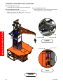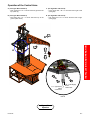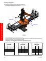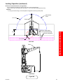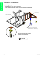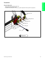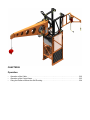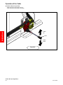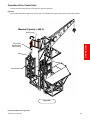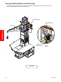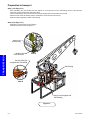
1
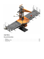
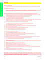
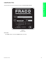
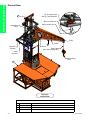
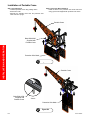
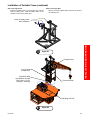
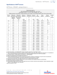
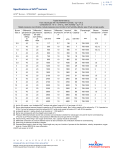
Annex B
FRH
User’s Guide
FRH-4000 r.04-09/2007
Congratulations!
You are about to use the excellent FRACO FRH-4000 portable crane system! This system stands out for its safety, stability and
flexibility.
All rights reserved. Any reproduction, in part or in whole, is prohibited without the written consent by Les Produits FRACO Ltée.
The instruction manual and safety rules presented on the following pages will safely guide you through all the possibilities of this
system. The platform cannot be sold or rented without this user’s guide.
Les Produits FRACO Ltée reserves the right to modify the portable crane or its manual without notice, and will not assume any
responsibility for any prejudices that may occur. The FRACO FRH-4000 portable crane system meets the OSHA and
CE EN 1495:1997F requirements, except for the non-applicable ring and pinion systems.
Les Produits FRACO Ltée
91 Chemin des Patriotes
St-Mathias-sur-Richelieu
Québec, Canada, J3L 6A1
www.fraco.com
[email protected]
St-Mathias-sur-Richelieu:
Canada:
Europe:
U.S.A.:
or by fax at:
FRACO is an ISO 9001 registered campany
(450) 658-0094
1-800-267-0094
+33 (0) 3.44.91.03.53
1-888-372 2648
(450) 658-8905
Warranty
Les Produits FRACO Ltée, hereafter referred to as FRACO, guarantees its new products against any material or
manufacturing defects for a period of one year from the date of delivery to the first user, or for a period of 12 months from the
date of delivery to the accredited dealer.
FRACO’s obligation and liability in virtue of this warranty are expressly limited to repairing or replacing with re-machined or new
materials, at FRACO’s discretion, any part which appears to have a material or manufacturing defect. These parts shall be
supplied free of charge according to the FOB terms of the dealer or user, at FRACO’s discretion.
Depending on the provisions of the service policy in force at the time of delivery, and in virtue of the provisions of this warranty,
FRACO shall pay the installation cost for any repaired or replaced part. FRACO shall not bear any labor costs unless written
authorization is obtained before the work begins.
This warranty does not apply to parts or accessories for products that were not manufactured by FRACO and which are covered
by a warranty from their own manufacturer, nor does it apply to normal maintenance (for example, motor tuning) or to parts used
in normal maintenance. FRACO offers no other warranty, either express or implicit, and gives no guarantee of commercial value
or pertinence for a given application.
FRACO’s obligation in virtue of this warranty does not cover customs duties, taxes or any other fees, nor does it bear any
liability for direct, indirect, incidental or resulting damage or delay. If FRACO so requests, the products or parts for which a
warranty claim is made must be returned to FRACO at the expense of the dealer or owner.
Any improper use, including use of the product after defective or worn parts have been discovered, shall cancel this warranty.
Other improper use that shall result in the cancellation of the warranty includes using the product beyond its rated capacity,
substituting other parts for FRACO-approved parts (including anchors), or any third-party alterations, modifications or repairs
which FRACO deems to have damaged the product.
Table of Contents
CHAPTER
A
CHAPTER
B
General Information
Warning . . . . . . . . . . . . . . . . . . . . . . . . . . . . . . . . . . . . . . . . . . . . . . . . . . . . . . . . . . . . . . . . . . . . . A-2
Indentification Plate . . . . . . . . . . . . . . . . . . . . . . . . . . . . . . . . . . . . . . . . . . . . . . . . . . . . . . . . . . . . A-3
General View . . . . . . . . . . . . . . . . . . . . . . . . . . . . . . . . . . . . . . . . . . . . . . . . . . . . . . . . . . . . . . . . . A-4
Installation and Operation
Installation of Portable Crane . . . . . . . . . . . . . . . . . . . . . . . . . . . . . . . . . . . . . . . . . . . . . . . . . . . . . B-2
Operation of the Control Arms . . . . . . . . . . . . . . . . . . . . . . . . . . . . . . . . . . . . . . . . . . . . . . . . . . . . B-5
Loading Capacities . . . . . . . . . . . . . . . . . . . . . . . . . . . . . . . . . . . . . . . . . . . . . . . . . . . . . . . . . . . . . B-6
CHAPTER A
General Information
•
•
•
Warning . . . . . . . . . . . . . . . . . . . . . . . . . . . . . . . . . . . . . . . . . . . . . . . . . . . . . . . . . . . . . . . . . . . . . .A-2
Identification Plate . . . . . . . . . . . . . . . . . . . . . . . . . . . . . . . . . . . . . . . . . . . . . . . . . . . . . . . . . . . . . .A-3
General View . . . . . . . . . . . . . . . . . . . . . . . . . . . . . . . . . . . . . . . . . . . . . . . . . . . . . . . . . . . . . . . . . .A-4
GENERAL INFORMATION
Warning
Safety is our first concern
-
For that reason, never remove or alter any part in order to adapt the portable crane to fit a specific area of the building.
Use only FRACO genuine parts
-
FRACO (and/or its importer / representative) cannot be responsible for any property damage, severe injury or death that
may result from failure to comply with the following safety recommendations, local rules and regulations.
Before operating this FRACO system, the following safety rules must be read and completely understood
1-
Unauthorized use is not permitted. You must be trained by an authorized FRACO representative or dealer. The operator
should be familar with the user’s guide and understand all the functions of this equipment.
2-
It is the responsibility of the operator to ensure that the proper load is not exceeded.
3-
Do not install the portable crane on a freestanding platform.
4-
The portable crane must never exceed the last anchor.
5-
Never assume anything. If you have questions concerning the operation of this FRACO system, STOP! Refer to the
proper user’s manual. If you are still unsure, do not continue and call FRACO immediately.
6-
Never replace components or parts without the consent of the manufacturer.
7-
This equipment is designed to be installed on the tower guard of a FRACO platform 20K only.
8-
Before operating the crane, all persons are to be alerted.
9-
The portable crane described herein is not designed for operations involving lifting or moving personnel.
10-
Do not lift or carry loads over people.
11-
Do not jerk the winch. Always smoothly accelerate and decelerate the loads.
12-
Do not operate a damaged, noisy or malfunctionning portable crane.
13-
Do not leave a load suspended for any extended period of time.
14-
Never leave a suspended load unattended.
15-
Inspect winch, rigging, mounting bolts and hoses before each shift.
16-
Warm-up equipment before operating the portable crane, particularly at low ambient temperatures.
17-
Wear proper clothing to avoid entanglement in rotating machinery.
18-
Always stay at a safe distance from the load.
19-
Maintain the portable crane and equipment in good operating condition. Perform scheduled maintenance regularly.
20-
Keep hands clear from the crane boom when winding wire cable onto the winch drum.
21-
Do not lift a load with a twisted, kinked or damaged wire cable.
22-
The replacement of the wire cable must be done by an authorized technician. Authorized technician must have level A2
FRACO mechanical licence.
23-
Maintain five wraps of wire cable on the cable drum at all times.
24-
Mark out with beacons and forbid the access under the lifting area.
25-
The load must be lifted vertically at a 2° angle (see chart in page B-6).
26-
Verify that the pulley can turn easily and the raised load cannot be lowered by itself
27-
If the warning panel on the equipment is damaged or missing , do not use and call your FRACO representative for a
replacement.
28-
If the guardrails are removed, wear your safety harness
29-
A minimum of (5) five wraps of wire rope should remain on the cable drum at all times
Always wear your safety harness when installing and dismantling the mast sections, the wall ties and when
manipulating the planks when passing the wall ties. Safety harnesses that meet the local safety code must be available
at all times for each person on the platform. A safety line, also conform to those codes and of sufficient length for the
working height of the platform must be available at all times on the platform.
A-2
User’s Guide
GENERAL INFORMATION
Indentification Plate
This plate is placed on the side of the protective cab engine and must be visible at all times.
91, CHEMIN DES PATRIOTES, ST-MATHIAS-SUR-RICHELIEU,
QUÉBEC, CANADA, J3L 6A1
SERIAL NO.
NO. SÉRIE
NO. SERIE
SERIE NR
Patent pending no: 9,114,943
MODEL
MODÈLE
MODELO
MODEL
FRH-4000
YEAR
ANNÉE
ANO
BOUWJAAR
Vertical travel speed
Vitesse de déplacement vertical
Velocidad de elevacion
Verticale verplaatsingsnel heid
MADE IN
FABRIQUÉ AU
HECHO EN
VERNAARDIDGD IN
}
0 - 7,2' / min
0 - 2,2 m / min
0 - 0,036 m / s
CANADA
Figure A.1
Identification plate
Serial number
YYY - ZZZZ = YY (Year of manufacture) ZZZZ (Portable crane number)
FRH-4000 - Annex B
A-3
GENERAL INFORMATION
General View
(2) Two Way Valve
with (2) Two Directions
3
Boom Control Arm
Cable Control Arm
Installation
Hook
View A
Pulley
2
A
Hydraulic
Cylinder
Boom
Winch
Steel Cable
(see chart on page B-7)
Crane
Structure
Self-Locking
Hook
1
Figure A.2
General View
List of Components
A-4
No.
Code
Description
1
10060018
20K Elevating Unit
2
12490118
Portable Crane for 20” x 20” Mast
3
12490118
Self-Erecting
User’s Guide
CHAPTER B
Installation and Operation
•
•
•
Installation of Portable Crane. . . . . . . . . . . . . . . . . . . . . . . . . . . . . . . . . . . . . . . . . . . . . . . . . . . . . .B-2
Operation of the Control Arms . . . . . . . . . . . . . . . . . . . . . . . . . . . . . . . . . . . . . . . . . . . . . . . . . . . . .B-5
Loading Capacities . . . . . . . . . . . . . . . . . . . . . . . . . . . . . . . . . . . . . . . . . . . . . . . . . . . . . . . . . . . . .B-6
Installation of Portable Crane
Step 1 (see Figure B.1)
- Unbolt the portable crane using a lifting device.
- Remove the bolts.
- Seperate the portable crane from the protection wire
mesh and set it up right.
Step 2 (see Figure B.2 and View A)
- Install the hoist on the protection wire mesh and bolt it
using (4) four bolts supplied with protection wire mesh.
Portable Crane
INSTALLATION AND OPERATION
Bolts BOA-2030
Supplied with
Portable Crane
Protection Wire Mesh
1
Figure B.1
Portable Crane
A
Bolts BOA-2030
Supplied with
Portable Crane
View A
Protection Wire Mesh
2
B-2
Figure B.2
User’s Guide
Installation of Portable Crane (continued)
Step 3 (see Figure B.3)
Step 4 (see Figure B.4)
- Install the portable crane on the elevating unit and fold
back the safety rollers. Install the safety rollers on the
portable crane using the safety pins.
- Bolt (4) four bolts supplied with protection wire mesh to
the elevating unit.
3
INSTALLATION AND OPERATION
Close the safety rollers
after installation.
Figure B.3
Portable Crane
User's Guide
Compartment
Bolts BOA-2030
with Washers and Nut
O3/4"-10unc x 5 1/2",
A325 galv. assembly
Protection Mesh
Elevating Unit 20K
4
FRH-4000
Figure B.4
B-3
Installation of Portable Crane (continued)
Step 5 (see Figure B.5, View A)
- Connect the crane’s hydraulic hose on the elevating unit.
INSTALLATION AND OPERATION
Step 6 (see Figure B.5, View B)
- Screw on the control arms on the control valve.
- These arms are in the user’s guide compartment
mounted on the protection wire mesh.
Step 7 (see Figure B.5, View A)
- When using the crane, you must ensure that the selector
of the elevating unit is on positon «CRANE».
Control arms
Control arms
B
View B
(bottom view)
From crane
From crane
A
View A
B.5
Figure B.5
Connection
B-4
User’s Guide
Operation of the Control Arms
A (see Figure B.6 and View A)
- Push control arm « A » to move load from ground to the
top (cable up).
C (see Figure B.6 and View A)
- Push control arm « B » to move the boom right to left
(swing left).
B (see Figure B.6 and View A)
- Pull control arm « A » to move load from top to the
ground (cable down).
B (see Figure B.6 and View A)
- Pull control arm « B » to move the boom left to right
(swing right).
INSTALLATION AND OPERATION
B
A
A
B
A
« A » (Up-Down)
Cable
control arm
« B » (Left-Right)
Boom
control arm
View A
Figure B.6
Operation
FRH-4000
B-5
Loading Capacities
The loading area is located on the each side of the elevating unit
- It is important to distribute the load on the platform.
- Refer to the platform user’s guide to know the proper load distribution.
INSTALLATION AND OPERATION
Loading Area
Loading Area
Figure B.7
Loading Area
- Valid for Braden Gearmatic Winch (Model: B64A05 119-01)
- The hydraulic pressure must be ajusted according to the cable diameter and the assembly of this cable must be done by a
person who has received « Level 3 » training given by FRACO.
- A minimum of (5) five wraps of wire rope should remain on the cable drum at all times.
- Always put loads in the loading area of the cantilever section (see Figure B.7).
Cable Dia.3/8 in
2,850 Psi
4,000 Lb Max
Cable Dia.5/16 in
1,850 Psi
2,500 Lb Max
Cable Dia.1/4 in
1,200 Psi
1,000 Lb Max
Layer
Length
Capacity
Layer
Length
Capacity
Layer
1
26’ 0”
4,000 lb
1
33’ 0”
2,500 lb
2
66’ 0”
4,000 lb
2
79’ 0”
2,500 lb
3
109’ 0”
4,000 lb
3
129’ 0”
4
156’ 0”
3,800 lb
4
5
B-6
Length
Capacity
1
43’ 0”
1,000 lb
2
100’ 0”
1,000 lb
2,500 lb
3
160’ 0”
1,000 lb
183’ 0”
2,500 lb
4
224’ 0”
1,000 lb
241’ 0”
2,500 lb
5
292’ 0”
1,000 lb
6
364’ 0”
1,000 lb
User’s Guide
Loading Capacities (continued)
Dimension of mouvement zone (see Figure B.8)
- 40 1/2” behind the elevating unit and the cable of the crane (see Profil View).
- Rayon 8’-7/8” of the mouvement zone and rayon 1’-9 1/2” of the self-erecting (see Plan View)
Important :
- For using the self-erecting, the minimal planks configuration must be (3) three planks.
Mouvement
Zone
R 8'-7/8"
Crane
INSTALLATION AND OPERATION
Minimum three planks
for using the self-erecting
34 1/2"
(2) two first planks
R 1'-9 1/2"
Plan View
Crane
40 1/2"
Profil View
Figure B.8
FRH-4000
B-7
User’s Guide
Self-Erecting
of FRH-4000
Self-Erecting of FRH-4000 - User’s guide r.00-09/2007
Table of Contents
CHAPTER
A
CHAPTER
B
CHAPTER
C
Installation
Preparation to Install. . . . . . . . . . . . . . . . . . . . . . . . . . . . . . . . . . . . . . . . . . . . . . . . . . . . . . . . . . . . A-2
Installation on the FRH-4000 . . . . . . . . . . . . . . . . . . . . . . . . . . . . . . . . . . . . . . . . . . . . . . . . . . . . . A-3
Installation of the Control Arm . . . . . . . . . . . . . . . . . . . . . . . . . . . . . . . . . . . . . . . . . . . . . . . . . . . . A-4
Connection . . . . . . . . . . . . . . . . . . . . . . . . . . . . . . . . . . . . . . . . . . . . . . . . . . . . . . . . . . . . . . . . . . . A-5
Operation
Operation of the Cable . . . . . . . . . . . . . . . . . . . . . . . . . . . . . . . . . . . . . . . . . . . . . . . . . . . . . . . . . . B-2
Operation of the Control Arm . . . . . . . . . . . . . . . . . . . . . . . . . . . . . . . . . . . . . . . . . . . . . . . . . . . . . B-3
Using the Platform Without the Self-Erecting . . . . . . . . . . . . . . . . . . . . . . . . . . . . . . . . . . . . . . . . . B-4
Transportation
Preparation to transport . . . . . . . . . . . . . . . . . . . . . . . . . . . . . . . . . . . . . . . . . . . . . . . . . . . . . . . . . C-2
CHAPTER A
Installation
•
•
•
•
Preparation to Install . . . . . . . . . . . . . . . . . . . . . . . . . . . . . . . . . . . . . . . . . . . . . . . . . . . . . . . . . . . .A-2
Installation on the FRH-4000 . . . . . . . . . . . . . . . . . . . . . . . . . . . . . . . . . . . . . . . . . . . . . . . . . . . . . .A-3
Installation of the Control Arm . . . . . . . . . . . . . . . . . . . . . . . . . . . . . . . . . . . . . . . . . . . . . . . . . . . . .A-4
Connection. . . . . . . . . . . . . . . . . . . . . . . . . . . . . . . . . . . . . . . . . . . . . . . . . . . . . . . . . . . . . . . . . . . .A-5
INSTALLATION
Preparation to Install
Step 1 (see Figure A.1)
- Cut the Tie-Raps.
- Unscrew the pins.
- Remove the pins.
Self-Erecting
Pin supplied with
self-erecting
Pin supplied with
self-erecting
1
A-2
Figure A.1
User’s Guide
INSTALLATION
Installation on the FRH-4000
Step 2 (see Figure A.2)
- Position the self-erecting on the crane structure.
- Fix the self-erecting with two pins supplied with the self-erecting.
- Screw the pins.
Self-Erecting
Crane Structure
A
Pins with Bolts
Supplied with Self-Erecting
View A
2
Self-Erecting of the FRH-4000
Figure A.2
A-3
INSTALLATION
Installation of the Control Arm
Step 3 (see Figure A.3)
- Unscrew the (2) two bolts under the self-erecting.
- Position and bolt the control arm with the (2) two bolts supplied with the self-erecting.
Self-Erecting
Crane Structure
B
Control Arm for Self-Erecting
Supplied with the Self-Erecting
Bolts with Lock Washers and Washers
Supplied with the Self-Erecting
View B
A-4
3
Figure A.3
User’s Guide
INSTALLATION
Connection
Step 4 (see Figure A.4)
- Remove the fitting cap and the plastic cap.
- Connect the hose tube to the valve.
- Screw the Lever (This lever is in the user’s guide comparment. See Figure B.4 on page B-3).
Hose Tube
Fitting Hose 45°
Plastic Cap
Fitting Cap
Fitting 90°
Lever
4
Self-Erecting of the FRH-4000
Figure A.4
A-5
CHAPTER B
Operation
•
•
•
Operation of the Cable. . . . . . . . . . . . . . . . . . . . . . . . . . . . . . . . . . . . . . . . . . . . . . . . . . . . . . . . . . .B-2
Operation of the Control Arms . . . . . . . . . . . . . . . . . . . . . . . . . . . . . . . . . . . . . . . . . . . . . . . . . . . . .B-3
Using the Platform Without the Self-Erecting. . . . . . . . . . . . . . . . . . . . . . . . . . . . . . . . . . . . . . . . . .B-4
Operation of the Cable
Operation Cable (see Figure B.2)
- Raise the lever and the cable move up.
- Lower the lever and the cable move down.
OPERATION
Cable
Up
Lever
Cable
Down
Figure B.1
Control Arm (see Figure B.2)
B-2
User’s Guide
Operation of the Control Arm
- To move the self-erecting above the mast sections, used the control arm.
Important
- Once the last mast section reaches the security device, the portable crane stops but the cable of self-erecting operates.
Maximal Capacity = 400 lb
Self-Erecting
OPERATION
Control Arm
Supplied with
Self-Erecting
Strap
Mast Section
Figure B.2
Using the platform (see Figure B.3)
Self-Erecting of FRH-4000
B-3
Using the Platform Without the Self-Erecting
- Turn the self-erecting to exterior of crane structure and attach the self-erecting to the handle of the crane structure.
- Raise the cable to tighten the cable of the self-erecting.
Self-Erecting
Self-Erecting
Crane
OPERATION
A
Hook of the
Self-Erecting
View A
Figure B.3
B-4
User’s Guide
CHAPTER C
Transportation
•
Preparation to transport . . . . . . . . . . . . . . . . . . . . . . . . . . . . . . . . . . . . . . . . . . . . . . . . . . . . . . . . . C-2
Preparation to transport
Step 1 (see Figure C.1)
- After dismantling the mast sections and the platform is on the ground, turn the self-erecting into the crane structure
(the boom must be pointed at the side of the valve).
- Fix the self-erecting on the crane structure with the pin supplied with crane structure (see View B).
- Attach the hook of the self-erecting into the handle of the crane structure (see View A).
- Raise the cable to tighten the cable of self-erecting.
Step 2 (see Figure C.1)
- Remove the crane with wire mesh protection
- Install to transport as shown in Figure C.1.
Hook of the
Self-Erecting
TRANSPORTATION
Handle of the
Crane Structure
View A
Pin and Safety Pin
Supplied with FRH-40000
Self-Erecting
View B
B
A
Control Arm Supplied with
Self-Erecting
Figure C.1
C-2
User’s Guide