1
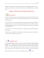
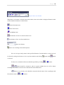
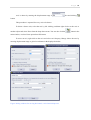
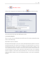
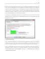
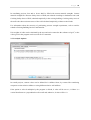
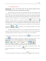
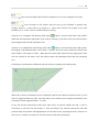
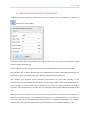
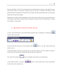
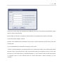
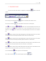
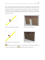
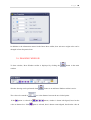
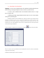
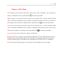
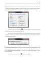
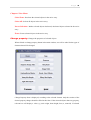
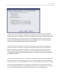
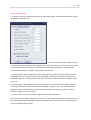
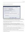
StatiCAD-Yigma
USER MANUAL
V.3.0.0.0
Page 1
TABLE OF CONTENTS
Chapter 1 Introduction
1.1 StatiCAD-Yigma Software Description
5
1.2 General Technical Features of the Software
5
Chapter 2 Installing the Software on PC
7
2.1 Installing the Main Software
7
2.2 Installing Supporting Programs
7
2.2.1 Pdf Creator Software
7
2.2.2 Adobe Reader Software
8
2.2.3 Vector Draw Lite File Converter Software
8
2.3 Running the Software
8
2.3 Updating the Software
8
Chapter 3 Data Entry with Graphic Editor (Draw)
3.1 Select Mode
9
3.2 Draw Axis
9
3.3 Draw Wall
13
3.4 Draw Slab
16
3.5 Draw Horizontal Bond Beam
21
3.6 Draw Vertical Bond Beam
22
3.7 Draw Door
24
3.8 Draw Window
26
Page 2
3.9 Draw Foundation
29
3.10 Draw Retrofit Jacket
30
Chapter 4 File Menu
New
32
Open
32
Save
32
Save As
32
Rescue Last Project
32
Exit
32
Chapter 5 Edit Menu
33
Undo
33
Redo
33
Copy Story .
33
Erase
34
Selection Mode
34
Make All Objects Unselected In the Story
34
Make All Objects Selected In the Story
34
Invert Selection in the Story
34
Filter Selection
35
Find Object
35
Page 3
Chapter 6 View Menu
36
Chapter 7 Modify Menu
Selected Element Properties
36
Chapter 8 Analysis
Load Transfers in a Story
38
Load Transfers between Stories
40
Performance and Retrofit
41
Determining The Earthquake Performance Of Existing Building
41
Drawing Retrofit Jackets
43
Retrofitted Building Analysis Options
46
Page 4
This page was intentionally left blank.
Page 5
Chapter 1 Introduction
1.1 StatiCAD-Yigma Software Description
StatiCAD-Yigma is computer software that functions in static analysis and project drawings
of masonry constructions as per earthquake code.
The software can perform static calculations and drawings of masonry constructions in
accordance with earthquake code 2007.
The software at once resolves the building system constructed with axis, wall, slab, horizontal
bond beam, vertical bond beam, door basic elements drawn in the graphic interface; regarding
analysis options. Performed analysis include earthquake code 2007 geometry checks, shear
and mass center checks, shear and vertical stress checks on walls, slab calculations, and
preparing report files.
All project drawings including project cover can be collected at once with a single
button. Drawings can be edited by the integrated drawing editor, or can be exported to graphic
design software like AutoCAD.
1.2 General Technical Features of the Software
1.2.1 A complete modeling of the building by basic elements: axis, wall, slab, horizontal
bond beam, vertical bond beam, door, window
1.2.2 Ease of editing and use by commands like undo, redo, find object, zoom in, zoom out,
layer, calculate distance, auto-name elements, merge walls, select all, select none,
invert selection, delete object, copy object, change object properties
1.2.3 Customized pop-up menu based on the right-clicked element
1.2.4 Zoom function by scrolling center mouse wheel, pan function by clicking center
mouse wheel and dragging
1.2.5 Selective reporting based on analysis results (horizontal bond beam loads, wall loads,
slab calculations, earthquake loads on stories, shear and mass center summary table,
Page 6
shear center coordinates, wall shear forces, wall vertical stress checks, wall shear
stress checks)
1.2.6 Creating evaluation report for the building by terms from the earthquake code
regarding masonry buildings
1.2.7 Saving reports and drawings in PDF format
1.2.8 Automatically drawing section details for project drawings
1.2.9 Selective story copying
1.2.10 While drawing, following operations can be performed optionally: Automatic setting
of sheet size, automatic adding project cover, foundation application plan and
foundation bond beam detailed drawings, drawing wall plan, displaying door and
window locations in wall plan, adding horizontal and vertical bond beam detailed
drawings to wall plan or formwork plan, drawing formwork sections and slab
reinforcements.
1.2.11 Drawings can be edited in internal drawing editor or exported as dxf/dwg file format
without shape loss.
1.2.12 Integrated multi-functional drawing editor for organizing, modifying and printing
project drawings
1.2.13 Fault checks after analysis: Displaying construction elements with insufficient sections
and walls with insufficient lengths
1.2.14 Retrofitting calculations and reports
1.2.15 Retrofitting section drawings
Page 7
Chapter 2 Installing the Software on PC
2.1 Installing the Main Software
2.1.1 Run the StatiCAD-Yigma_Setup_v3.xxx.exe setup file provided in the installation CD.
2.1.2 Click "İleri" (Next) in the displayed form. If you agree with the terms, click " Lisans
sözleşmesini tüm maddeleri ile kabul ediyorum" (I accept all articles of the license
agreement) option, and then click "İleri" (Next).
Do not change the installation directory “C:\Program Files\StatiCAD Yigma” . Click "Başlat"
(Start) for starting the installation.
When the software is automatically installed and "StatiCAD-Yigma Başarı ile kuruldu"
(StatiCAD-Yigma has been installed successfully) message is displayed, the installation is
completed.
2.1.3 Exit installation by clicking "İleri" (Next) and "Çıkış" (Exit) buttons.
2.2 Installing Supporting Programs
StatiCAD-Yigma comes with a bundle of supporting programs for full functionality. You can
find the supporting programs in the installation CD, in supporting programs folder.
Supporting programs and their functions are listed below. Supporting programs are not
provided with the demo version. They can be downloaded from our website
http://www.staticad-yigma.com .
2.2.1 Pdf Creator Software: This program enables you to save report and drawing files
created by StatiCAD-Yigma in PDF format. It also allows any printable document to be
converted into PDF format. For personal uses, you can convert any document to PDF by
selecting PDF creator as a printer in your print menu and clicking "Print" button. This is a
freeware program.
Page 8
To install PDF Creator, run the PDFCreator-x_x_x_setup.exe program located in C:\Program
Files\StatiCAD Yigma\ supporting programs. Do not change the printer name during
installation.
If the software is already installed in your computer, the installation may not be completed. In
this case, you can remove the old program (Control Panel/Add or Remove Programs) and
install the new version.
You can download the new version of the freeware PDF Creator program from our website
www.staticad-yigma.com or http://www.pdfforge.org/ .
2.2.2 Adobe Reader Software: Enables you to display the documents created by the software
or other programs in PDF format. If the software is already installed, you can skip reinstalling
it.
To install Adobe Reader, run the AdbeRdrxxx_tr_TR.exe program located in C:\Program
Files\StatiCAD Yigma\ supporting programs.
You can download the latest version of the software from http://get.adobe.com/reader/
2.3 Running the Software: Attach the program dongle provided with the installation CD to
your computer. Installation of the dongle will be performed automatically. When the dongle is
attached for the first time, automatic installation generally takes less than 60 seconds. After
the dongle is recognized by the computer, a success message is displayed. Now you can run
StatiCAD-Yigma software.
We hope you enjoy your experience with this software...
2.4 Updating the Software: Run the StatiCAD-Yigma_3_xxx_Guncelleme_Setup.exe
program. Click "İleri" (Next) in the displayed form. If you agree with the terms, click "Lisans
sözleşmesini tüm maddeleri ile kabul ediyorum" (I accept all articles of the license
agreement) option, and then click "İleri" (Next).
Do not change the installation directory “C:\Program Files\StatiCAD Yigma” . Click "Başlat"
(Start) for starting the installation.
When the software is automatically installed and "StatiCAD-Yigma Başarı ile kuruldu"
(StatiCAD-Yigma has been installed successfully) message is displayed, update is completed.
Page 9
Upgrade or downgrade can be performed by this process. By installing the update, you will
upgrade your program to the current version, whether you have installed the previous versions
or not.
Chapter 3 Data Entry with Graphic Editor (Draw)
3.1
Selection Mode
Only one construction object is active in project data entry in Draw menu. Project objects may
first need to be selected, in order to modify them. Toggle selection mode to select objects and
exit drawing mode.
To enter selection mode, you can either click the selection mode button in the Draw toolbar of
the main window, or you can click Selection Mode option in Draw menu. When the object is
in drawing mode (wall, slab, etc.) a right click will automatically cancel the active mode and
enter selection mode.
To select objects, you can create a selection frame. Clicking on the objects will also select or
deselect them.
To create a selection frame, first and second points of the frame is marked by left mouse click.
Selected objects are displayed in orange color.
3.2-
DRAWING AXIS
Axes should necessarily be drawn first, in order to perform any drawing in StatiCAD-Yigma
software. Axes are drawing guides that ensure the project is carried out by sharp and absolute
measures. As static calculations are based on axes; static connections between elements connected to
different axes in walls, horizontal bond beams and slabs in the same story cannot be considered.
However, sharing axes of same coordinates or names is not necessary for the objects to perform load
transfer between stories. Draw Axis toolbar can be displayed by clicking
button.
P a g e 10
Figure: Draw Axis Toolbar
When Draw Axis button is clicked in the main window, draw axis toolbar is displayed. Buttons in this
toolbar and their functions are listed below.
Draw Horizontal Axis
Draw Vertical Axis
Draw Oblique Axis
Get distance of new axis from last drawn axis
Get distance of new axis from marked axis
New axis distance
Draw axis according to the marked options
If no axis was previously drawn in the specified direction, first horizontal or vertical axis can
be drawn by setting axis distance to 0 (or any other number) and clicking
button when
button
is selected.
To draw axis, orientation of the axis should be specified by clicking
or
or
button.
button should be selected in order to specify whether the axis will be drawn
according to the distance from last axis or the distance from marked axis.
If
button is on, reference axis should be selected with left mouse click, accordingly with
the selection status of
or
buttons.
P a g e 11
Axis is drawn by entering the displacement range in
box and clicking
button.
This procedure is repeated for every axis to be drawn.
To delete a drawn axis, select the axis by left clicking; and then right click over the axis or
another object and select Erase from the drop-down menu. You can also click the
button in the
main window, or select Erase option from Edit menu.
To move an axis, right click on the axis and select Axis Property Change. Move the axis by
entering displacement range or global coordinates in the displayed window.
Figure: Dialog windows for moving horizontal, vertical and oblique axis
P a g e 12
To draw an oblique axis, orthogonal drawing mode (ortho) option
To draw an oblique axis,
should be disabled.
button is selected; first and second points of the oblique axis are marked
in the main window, regarding the intersection points of previously drawn axes.
To erase an incorrect oblique axis, left click on an empty area on the axis, then click erase command in
the right-click menu or Edit menu.
P a g e 13
3.3-
DRAWING WALL
To draw walls, wall properties form is displayed by clicking the
button in the main window.
There are three tabs for data entry in the Wall Properties window.
3.3.1 General Settings Tab
There is no need to enter any information in the wall ID section. The software automatically assigns
names to walls while drawing.
Wall widths are entered as centimeters.
Horizontal bond beam height over the wall is entered. Horizontal bond beam width over the wall is
automatically generated as the width of the wall stated here. Horizontal bond beam over the wall is
automatically drawn when the wall is drawn. No additional bond beam should be defined over the
wall. If additional bond beams are defined over the wall; the slab load would be distributed both to the
wall and horizontal bond beam, and the bond beam would transfer the load to the construction
elements at endpoints; so load transfer would be performed twice. To avoid such error, no horizontal
bond beam should be defined over the wall. Horizontal bond beams over the wall are automatically
generated.
P a g e 14
Wall Top Level value is the distance between story top coordinate point and horizontal bond beam top
level over the wall. Wall Bottom Level is the distance of the wall base from the story base defined in
general story settings. Wall Bottom Level value should be zero except for gradual buildings. Distance
values are positive (+) for up, negative (-) for down. Story coordinate settings and descriptions are
performed in general story settings. If you prefer to draw a wall of the same height as the story, Wall
Top Level and Wall Bottom Level values should remain zero.
For example, for a wall with the wall top level 1m below the story top level, wall top level value
should be set to -100. After the value is set, horizontal bond beam top level over the wall would be 100
cm below the story level.
3.3.2 Static/Material Tab
If one of the defined walls E1-E7 is selected; wall unit weight, pressure safety stress of wall and
cracking safety stress of wall values are selected from earthquake code tables and entered in relevant
boxes. If E1-E7 defined material is used, those values need not be changed and are colored green.
Table 5.3 of Earthquake Code 2007 is used for Pressure Safety Stress of Wall value (fem) that is
automatically selected. If desired, user can perform modeling by entering values obtained from
methods within the scope of Turkish Earthquake Code 2007, 5.3.2 Pressure Safety Stress on Walls or
other methods and experiments.
P a g e 15
In retrofitting projects, fem and to boxes shall be filled with current material strengths. Current
material strengths are Pressure Safety Stress of Wall (not reduced according to slenderness ratio) and
Cracking Safety Stress of Wall, obtained empirically in the existing building. Cracking safety stress of
the wall is the shear resistance stress of the wall calculated empirically, without vertical loads.
For information about the necessity of performing pressure strength experiments, refer to articles
related to Existing Building Reviews and Retrofits.
Unit weights of walls can be calculated by the user and can be entered to the software as kg/m3; or the
values given in the program can be used for E1-E7 materials.
3.3.3 Analysis Options
In retrofit projects, custom values can be defined for k stiffness factor, by reasons like considering
composite section relative stiffness or using different relative wall stiffness.
If the option to select k multiplier by the program is clicked, k value will be set to 1,2 if there is a
vertical bond beam or a perpendicular wall at wall end; otherwise, k value will be 1.0.
P a g e 16
3.4- DRAWING SLAB
Important note: In order to perform load transfer, slab edge should be supported from the
center of the element (static axis), to which load will be transferred.
In StatiCAD-Yigma software, slabs are used for transferring loads and self weights to walls.
Slab calculation axes enable the reinforcement calculations of concrete slabs. Lack of slab calculation
axis in an area where a slab is present would result in lack of concrete slab calculation and drawing
operations. Similarly, lack of slab in an area where slab calculation axis is present would cause lack of
load transfer from the calculation axis to wall; and slab calculation axis weights cannot be used in
earthquake calculations. When slab is created with rectangular slab
or quadrilateral slab
commands, slab calculation axes are automatically generated with the same properties. In slabs with
special shapes like L, T, Z, H; slab calculation axes' coordinates should be changed in order to draw
slab reinforcements in a proper way. In such situations, slab calculation axes can be modified with
commands like
,
and
. As calculation axes are automatically generated except special
conditions, no other operation is necessary.
By definition, different G and Q loads, levels, slab heights and supporting conditions can be
applied to slabs and slab calculation axes. So, when you change G, Q, K, Level values of drawn slabs,
you should change slab calculation axis properties as well (if there are no special conditions).
To draw slab, slab properties form is displayed by clicking the
When
button in the main window.
button is selected, (slab toolbar is displayed) slab drawing mode is active.
Total coating load except self concrete weight (ceiling coating+leveling concrete under
coating+coating weight+etc..) is entered in the
box in Draw Slab toolbar. Entry unit is
kg/m2.
Live load on the slab and slab calculation axis is entered in the
box in Draw Slab toolbar.
P a g e 17
is the concrete height of slab and slab calculation axis. It can be changed if necessary.
is the elevation of slab surface from the story up level defined in general story
settings. Positive (+) values refer to up, negative (-) values refer to down. For example, Level value
should be set as -25 for a slab 25 cm below the story ceiling.
Software is in rectangular slab drawing mode when
button is selected in the Draw Slab toolbar.
When top left and bottom right points of the slab are selected by left mouse click, the software draws
the rectangular slab and slab calculation axes.
Software is in quadrilateral slab drawing mode when
button is selected in the Draw Slab toolbar.
Rectangular or quadrilateral slabs can be drawn. To define slab, four corners should be clicked in the
main window, with respect to nodes. When top left, bottom right, bottom left, top right points of the
slab are selected by left mouse click, the software draws the quadrilateral slab and slab calculation
axes.
If clickings are performed in a different order, the software rearranges the clicking order.
When slab is drawn, load transfer areas are displayed (with bisectors drawn from slab corners) as if all
slabs are supported from four sides. After the analysis, the software tries to display load transfer areas
accurately for slabs supported from 1-2-3 sides.
If any slab bisector intersection points (blue inner lines) are present outside the slab, it will be
convenient to erase the slab and redraw it. After the analysis, the software detects the slabs that
perform faulty load transfer and highlight those on the main screen, reporting the slab is incorrect. In
such cases, it would be convenient to erase the incorrect slab and rerun analysis.
P a g e 18
While transferring loads from the slab to horizontal bond beams and walls, StatiCAD-Yigma linearizes
load transfers compared to triangular and trapezoid areas and performs load transfer to connected
elements. In order to perform load transfer, slab edge should be supported from the center of the
element (static axis), to which load will be transferred.
If there are no bearing elements in the entirety of slab edge, there is not any problem with load
transfer. However, slab concrete calculations can only be carried out in four-side and one-side
supported slabs (cantilever). Efforts were taken in order to preserve safety for two and three side
supported slabs.
If there are no bearing elements (wall, horizontal bond beam) in parts of slab edge, no load transfer is
performed in those parts. As the calculations slightly differ for slabs of L, T, +, H, etc. shapes; a user
willing to make more accurate calculations can place horizontal bond beams next to slab edges, in
order to maintain continuity.
Slab static and concrete calculations are performed with regard to the simple method presented in
TS.500. The user must investigate the situations that the method can be used; and must perform slab
calculations as well where the method cannot be used.
When slab is created with rectangular slab
or quadrilateral slab
commands, slab
calculation axes are automatically generated with the same properties. In slabs with special shapes like
L, T, Z, H; slab calculation axes' coordinates should be changed in order to draw slab reinforcements
in a proper way. In such situations, slab calculation axes can be modified with commands like
and
,
. As calculation axes are automatically generated except special conditions, no other
operation is necessary.
When delete
command is active in Draw Slab toolbar, slab calculation axis can be deleted
by clicking on it.
When edit
command is active in Draw Slab toolbar, after deleting slab calculation axis, a
new axis with the same properties can be created by clicking top left, bottom right, bottom left and top
right points of the slab calculation axis.
P a g e 19
When
command is active in Draw Slab toolbar, a new axis can be created by clicking top
left, bottom right, bottom left and top right points of the slab calculation axis. A new slab calculation
axis is created.
Note:
and
commands create slabs and slab calculation axes at the same time, where
command only creates slab calculation axis. It does not recreate the slab used in load transfer and
earthquake calculations. Except for special conditions,
and
commands will suffice.
If a wall is defined over the slab, no load transfer is performed between up story walls and down story
slabs. Hence, when it is necessary to define wall over the slab, it would be convenient to draw
horizontal bond beam under the wall (down story ceiling) If no horizontal bond beam is present, beam
height can be equal to slab height.
button opens a window, from which Draw Slab toolbar settings can be performed in
another form. This feature is not necessary for new slabs and slab calculation axes to be drawn. When
slab or slab calculation axis properties will be changed, property changes are done in this form.
There is no need to enter any information in the Slab ID section. The software automatically assigns
names while drawing.
P a g e 20
H Slab thickness is entered as centimeters.
Slab concrete dead load should not be entered while entering slab coating weight per unit area. The
software automatically calculates the dead load of the slab, regarding slab thickness. Weights of
coating materials over and under the slab concrete are calculated and values (coating, screed, drop
ceiling, ceramic, timber, etc.) are entered in kg/m2.
Slab live load should be selected by the user, as per TS.498 terms.
After entering data in Draw Slab form, the window is closed by clicking OK. Desired number of slabs
are drawn by marking first and second points, so that they go through the axis intersections drawn
earlier.
In order to keep the program in Drawing mode, Draw Slab toolbar should not be closed while
drawing.
P a g e 21
3.5- DRAWING HORIZONTAL BOND BEAM
To draw horizontal bond beam, horizontal bond beam properties form is displayed by clicking the
button in the main window.
There is no need to enter any information in the Beam ID section. The software automatically assigns
names to beams while drawing.
Beam widths are entered as centimeters. Beam width is recommended to be equal to wall width.
Beam height value is entered. Beam height is recommended to be equal to horizontal bond beam over
wall for short gaps, and for the long gaps it should satisfy deflection requirements.
The software pays attention to the horizontal bond beams over wall while drawing. It also
automatically generates horizontal bond beams over door and window. Horizontal bond beams over
door or window are erased, when a door or window is erased. They are moved when a door or window
is moved. After drawing door or window, the user should not draw any horizontal bond beams in that
area.
Static and concrete calculations are not performed by the software, as horizontal bond beams are
generally used in short gaps. Use of beams with long gaps is not recommended; however, if they are
used, static and concrete calculations and drawings must be completed independently. The software
constructively draws the horizontal bond beam reinforcements in line with the earthquake code.
P a g e 22
If a wall is defined over the slab, no load transfer is performed between up story walls and down story
slabs. Hence, when it is necessary to define wall over the slab, it would be convenient to draw
horizontal bond beam under the wall (down story ceiling) If no horizontal bond beam is present, beam
height can be equal to slab height.
Bond beams are used in masonry buildings, as they ensure that vertical loads are evenly transferred to
walls and the slabs function according to the calculation estimates (lowers slab deflection by creating
extra stiffness over the walls).
3.6- DRAWING VERTICAL BOND BEAM
To draw vertical bond beam, vertical bond beam properties form is displayed by clicking the
button in the main window.
Vertical bond beam drawing can be performed when
button is on and vertical bond beam
toolbar is active.
Vertical bond beams are drawn by clicking twice on the main window. First click marks the reference
point of the beam. Second click defines the drawing direction of the beam.
The value to be entered in
box is the distance between the two clicked points.
If the leftmost option is selected in
based on the value in distance box.
buttons, vertical bond beam is drawn left-aligned,
P a g e 23
There is no need to enter any information in the Beam ID section. The software automatically assigns
names to beams while drawing.
Beam widths are entered as centimeters. Beam width is recommended to be equal to wall width.
Vertical bond beam length is entered.
Distance From Marked Point determines how far the vertical bond beam will be drawn from the
clicked point.
It is recommended that you keep the eccentricity value as zero.
To draw vertical bond beam, you must left-click twice on the main window. First clicked point marks
the node of the vertical bond beam. If the second clicked point is horizontally in line (or close) with
the first one, vertical bond beam is drawn horizontally (x-x axis oriented). If the second clicked point
is vertically in line (or close) with the first one, vertical bond beam is drawn vertically (y-y axis
oriented).
P a g e 24
3.7- DRAWING DOOR
To draw door, Draw Door toolbar is displayed by clicking the
button in the main
window.
Door drawing can be performed when
The value to be entered in
If the
box is the distance between the two clicked points.
option is selected in
in distance box. If the
distance box. If the
button is on and Draw Door toolbar is active.
buttons, door is drawn left-aligned, based on the value
option is selected, door is drawn center-aligned, based on the value in
option is selected, door is drawn right-aligned, based on the value in distance
box.
When
button is selected, if the second clicked point is to the right of the first one, the software
uses the distance between clicked point and the left side of the door as node distance.
When
button is selected, if the second clicked point is to the left of the first one, the software
uses the distance between clicked point and the right side of the door as node distance.
When
button is selected, if the second clicked point is above the first one, the software uses the
distance between clicked point and the bottom side of the door as node distance.
When
button is selected, if the second clicked point is below the first one, the software uses the
distance between clicked point and the top side of the door as node distance.
It is recommended that
Door width is entered in
button is kept active for functionality.
box and door height is entered in
box.
P a g e 25
Doors are drawn by clicking twice on the main window. First click marks the reference point of the
door. Second click defines the drawing direction of the door. Performing the first click on the axis
intersection point and the next one towards the moving distance over the axis would be appropriate for
dividing the wall on the axis and the door to be integrated with the wall. If the door is correctly drawn
on the wall, the software will automatically divide the wall into two parts and will create horizontal
bond beam over the door.
Figure: Correct wall drawing in plan view
Correct wall drawing in 3D view
Figure: Incorrect wall drawing in plan view
Incorrect wall drawing in 3D view
button allows you to modify additional door properties that are not displayed in the toolbar. It is
used for extra modifications. Clicking
button displays the Door Properties form.
P a g e 26
In addition to the information entered in the Draw Door toolbar, door unit area weight value can be
changed in Door Properties form.
3.8- DRAWING WINDOW
To draw window, Draw Window toolbar is displayed by clicking the
button in the main
window.
Window drawing can be performed when
The value to be entered in
If the
option is selected in
value in distance box. If the
button is on and Draw Window toolbar is active.
box is the distance between the two clicked points.
buttons, window is drawn left-aligned, based on the
option is selected, door is drawn center-aligned, based on the value in
P a g e 27
distance box. If the
option is selected, door is drawn center-aligned, based on the value in distance
box.
When
button is selected, if the second clicked point is to the right of the first one, the software
uses the distance between clicked point and the left side of the window as node distance.
When
button is selected, if the second clicked point is to the left of the first one, the software
uses the distance between clicked point and the right side of the window as node distance.
When
button is selected, if the second clicked point is above the first one, the software uses the
distance between clicked point and the bottom side of the window as node distance.
When
button is selected, if the second clicked point is below the first one, the software uses the
distance between clicked point and the top side of the window as node distance.
It is recommended that
window width is entered in
button is kept active for functionality.
box and window height is entered in
box.
Windows are drawn by clicking twice on the main window. First click marks the reference point of the
window. Second click defines the drawing direction of the window. Performing the first click on the
axis intersection point and the next one towards the moving distance over the axis would be
appropriate for dividing the wall on the axis and the window to be integrated with the wall. If the
window is correctly drawn on the wall, the software will automatically divide the wall into two parts
and will create horizontal bond beam over the window.
Figure: Correct window drawing in plan view
Correct window drawing in 3D view
P a g e 28
Figure: Incorrect window drawing in plan view
Incorrect window drawing in 3D view
button allows you to modify additional window properties that are not displayed in the toolbar. It
is used for extra modifications. Clicking
button displays the Window Properties form.
In addition to the information entered in the Draw Window toolbar, window unit area weight value and
parapet height of window can be changed in Window Properties form. Parapet height of window is
equal to the height of wall section between top of slab and bottom of window (height of bottom of
window from top of slab).
P a g e 29
3.9- DRAWING FOUNDATION
Important: 1- In order to detect foundation under wall, foundations should be defined from the
static axis that goes through the midpoint of walls (eccentricity is possible if desired).
2- In order to detect foundation under wall, foundations should be drawn as a single
piece covering the walls.
3- Modeling by drawing a single foundation under all walls of an axis is a better method,
with regards to performing step 2.
Foundations should be drawn in foundation story. When you perform copy operation from the
basement to foundation story, the axes are copied into foundation story. For this operation, select
foundation story in the window displayed by clicking Copy Story button when the active story is the
basement story. Later, when foundation is the active story, copied basement axes and wall projections
will ease the drawing of foundation.
To draw foundation, Foundation form is displayed by clicking the
button in the main window.
There is no need to enter any information in the Foundation ID section. The software automatically
assigns names while drawing.
Foundation width and height is entered in centimeters.
P a g e 30
Left delta and right delta values define the extension length of the foundation from axis node, in
centimeters. This value can be set as half the foundation width of the opposite orientation.
Eccentricity is the distance of the virtual axis of the foundation center axis to the program axis.
Foundation top level value can be equal to wall bottom level value in gradual buildings and buildings
with English basements. Foundation top level value does not affect the way static calculations are
performed. In other words, the software can perform load transfer even if foundation bottom level
value is not changed in gradual buildings or buildings with English basement.
After setting foundation parameters, exit by clicking OK, and in the main window foundation is drawn
by clicking first and second points over the nodes.
3.10 - DRAWING RETROFITTING JACKET (SHOTCRETE)
Important: Retrofitting jacket should be modeled from the static axis passing through wall
center.
The term retrofitting jacket refers to the reinforcement operation completed with applying
steel mesh by shotcrete or repair mortar on wall, and applying reinforced concrete anchoraged to wall.
To draw retrofit jacket, Wall Retrofit Jacket form is displayed by clicking the
the main window.
button in
P a g e 31
Jacket ID is automatically generated by the software; so there is no need for a change. Wall
thickness is entered in centimeters. Wall and jacket eccentricity value should be left as zero. Jacket
Left/Down Delta Length determines the extension length to left or down, starting from the clicked
point; and Jacket Right/Up Delta Length determines the extension length to right or up, starting from
the clicked point. Concrete jacket thickness value is entered. If the building is not gradual or the top
level/bottom level values on walls are zero, top and bottom levels of concrete jacket should also be left
as zero.
If left or down side of the wall will be coated,
if right or up side of the wall will be coated,
radio button is selected;
radio button is selected.
If the walls are completely jacketed, the software can calculate the required steel bar
reinforcement in line with earthquake code 2008 7.F.4 formula. If the user desires to use a specific
value, one of the steel mesh options can be used.
After exiting with OK button, jacket is drawn by clicking first and second points in the axis of
the wall to be jacketed.
P a g e 32
Chapter 4 File Menu
New: Deletes current project and opens a new project. This command is not necessary in
startup. Command is also represented with
icon in the top toolbar.
Open: Opens a saved project. Projects saved by the software have .syp file extension. With
"Open" command, standard file open window is displayed and projects saved in any folder of
the computer can be opened. Command is also represented with
icon in the top toolbar.
Save: Saves current project. Projects saved by the software have .syp file extension. With
"Save" command, standard file save window is displayed and projects can be saved in any
folder of the computer. Command is also represented with
icon in the top toolbar.
Save As: Saves a copy of the project with a new filename.
Rescue Last Project: Projects exited without saving can be restored. When the last project is
loaded this way, undo and redo options are enabled for all operations performed in previous
session. If the last project is loaded as such, it should be saved with "Save As" command.
Exit: Exits by closing the program. You can also use the closing button on top right.
P a g e 33
Chapter 5 Edit Menu
Undo: Reverses all operations performed in the last session, step by step. Undo's can be done
any number of times. If you wish to undo operations from the previous session, you can load
the previous project at startup by "Rescue Last Project" option and perform undo operation.
Command is also represented with
icon in the top toolbar.
Redo: All operations that are undone can be repeated by Redo button. Command is also
represented with
icon in the top toolbar.
Copy Story: Copies the objects on the current story to other selected stories. Before
performing copy story operation, sufficient number of stories should be added to the project
by Settings/General Story Settings command or by clicking
button in the top toolbar.
Stories and construction elements to be copied are selected from the window displayed
by Copy Story command. If foundation story is selected among stories to be copied, the
software copies only the axes of the active story to the foundation story.
Copy Story command is also represented with
icon in the top toolbar.
P a g e 34
Erase: To erase desired objects, first the objects are selected, then Erase command is clicked.
Command is also represented with
icon in the top toolbar. If there are no selected objects
in the active story, the button is not active.
Selection Mode: Only one construction object is active in project data entry in Draw menu.
Project objects may first need to be selected, in order to modify them. Toggle selection mode
to select objects and exit drawing mode.
To enter selection mode, you can either click the selection mode button in the Draw toolbar of
the main window, or you can click Selection Mode option in Draw menu. When the object is
in drawing mode (wall, slab, vb.) a right click will automatically cancel the active mode and
enter selection mode.
To select objects, you can create a selection frame. Clicking on the objects will also select or
deselect them.
To create a selection frame, first and second points of the frame is marked by left mouse click.
Selected objects are displayed in orange color.
Command is also represented with
icon in the top toolbar.
Make All Objects Unselected In the Story: Deselects all objects. Command is also
represented with
icon in the top toolbar.
Make All Objects Selected In the Story: Selects all objects on the story with a single button.
After this command is performed, changing elements with Change Property command or
applying selection filter will be useful. Command is also represented with
icon in the top
toolbar.
Invert Selection In The Story: Makes selected objects deselected; deselected objects
selected. Command is also represented with
icon in the top toolbar.
P a g e 35
Filter Selection: Among all selected objects, keeps desired objects selected. In the form
displayed by clicking this command, keep the checkboxes of the elements that you wish to
keep selected as checked. Uncheck the elements that you wish to cancel their selection.
Command is also represented with
icon in the top toolbar. If there are no selected
objects in the active story, the button is not active.
Find Object: Selects an object on the story when the object name is known. After the
command is clicked, object name is entered in the displayed window, paying attention to
lowercase/uppercase letters.
Construction element is selected by "Bul ve Seç" (Find and select) button. This
command is particularly useful in selecting incorrect objects that were drawn successively and
the bottom objects cannot be selected or located. After Bul ve Seç (find and select) button is
used, selected object can be modified by clicking Erase button in edit menu or change
properties button.
Command is also represented with
icon in the top toolbar.
P a g e 36
Chapter 6 View Menu
Select None: Deselects the selected objects in the active story.
Select All: Selects all objects in the active story.
Invert Selection: Makes selected objects deselected; deselected objects selected in the active
story.
Erase: Erases selected objects in the active story.
Change property: Changes the properties of selected objects.
When clicked on change property button in the main window, one will be asked for the types of
elements that will be changed.
Change Property form is displayed, according to the selected element. Only the sections of the
desired property changes should be filled in this form. If the selected objects share any property,
relevant box will display a value (e.g. unit weight, beam height, fem, to, material). If selected
P a g e 37
object have different properties, relevant boxes will display zero or will be blank (e.g. wall ID,
wall width). Only the values related to the filled boxes will be changed in selected objects.
If Change Property option from the menu displayed by right-clicking on a selected object is
clicked, Change Property window of the hovered element will be displayed.
In addition, right clicking on any object in the drawing area allows changing property of the
hovered object.
P a g e 38
LOAD TRANSFERS
LOADS TRANSFERRED BY HORIZONTAL BOND BEAM
Description:
Horizontal bond beam: Horizontal beams over door or window gaps and in user-defined
building parts, with no filled walls or no walls underneath are referred to as horizontal bond
beam.
Horizontal bond beam over wall: Construction elements that evenly distribute the loads to
walls, where their width is same as the wall and their height is set from Draw Wall form.
The software automatically pays attention to the horizontal bond beams over wall
while drawing. Beams should not be drawn once more over drawn walls.
The software also automatically generates horizontal bond beams over door and
window. Horizontal bond beams over door or window are erased, when a door or window is
erased. They are moved when a door or window is moved. After drawing door or window, the
user should not draw any horizontal bond beams in that area.
Horizontal bond beams may be used for purposes like shrinking slab gaps, increasing
the stiffness of cantilever slabs, etc.
If the user-drawn horizontal bond beams are desired to transfer loads to walls, one of
the left or right ends of the beam should start from the wall axis.
Static and concrete calculations are not performed by the software, as horizontal bond
beams are generally used in short gaps. Use of beams with long gaps is not recommended;
however, if they are used, static and concrete calculations and drawings must be completed
independently. The software constructively draws the horizontal bond beam reinforcements in
line with the earthquake code.
Bond beams are used in masonry buildings, as they ensure that vertical loads are
evenly transferred to walls and the slabs function according to the calculation estimates
(lowers slab deflection by creating extra stiffness over the walls).
P a g e 39
The software transfers the distributed loads in the slabs to horizontal bond beams and
walls around, by automatically calculating dead weight. Horizontal bond beams receive load
from the following elements:
1- Self: Dead weight of element
2- Weights of Up Story walls; and dead and live loads on this walls
3- Slab dead and live loads connected to the axis in the story of the horizontal bond beam
4- Vertical bond beam loads on horizontal bond beam up story and that does not continue on
the story of horizontal bond beam (including external loads on vertical bond beam, both dead
and live)
5- Dead weight of the wall section over door or window below the horizontal bond beam
6- Dead weight of the door or window and dead weight of the parapet under the window on
horizontal beam up story
7- Dead and live loads of another horizontal bond beam anchoraged to the beam
Horizontal bond beams transfer load to the following elements:
1- Story walls, to which left or right end of the beam is connected (if there are multiple walls
at the left or right end of the beam, the loads to be transferred by the horizontal bond beam is
automatically divided to the number of walls)
a - If one end of the horizontal bond beam is at loose, the software automatically
considers it as a cantilever and transfers all loads to the construction element it is connected
to.
b - If both ends of the horizontal bond beam are at loose, a warning message is
displayed during analysis.
c - Horizontal bond beam separates received loads as G and Q and transfers loads
evenly to both ends.
Wall and Vertical Bond Beam transfers to be added to the Help file.
P a g e 40
LOAD TRANSFERS BETWEEN STORIES
As is known, earthquake code dictates that the walls should overlap. If load transfer
is desired in down story and up story walls, it is enough for the walls to overlap roughly.
Walls do not need to be drawn from the same axis for load transfer. Load transfer of the
walls
between
stories
is
performed
under
the
situations
listed
below.
As seen in the figures, load transfer is performed in the case that at least one edge
of the up story wall projection lies within down story walls. Load transfer of walls can be
controlled from wall load reports.
P a g e 41
Performance Evaluation and Strengthening of Masonry Constructions via StatiCAD-Yigma
Introduction
StatiCAD-Yigma software performs structural (static) calculations for masonry constructions as per
earthquake regulations based on the principles of the theory of elasticity.
Scope
Principles of calculations for masonry construction are mainly within the scope of the theory of
elasticity. (Allowable/Working stress method) Static and performance analyses of an existing
construction, static and performance analyses of strengthened buildings and composite section
investigations of strengthened buildings can be performed with StatiCAD-Yigma software.
In order to perform mentioned calculations, the checkbox “Project General
Settings>Performance>This project is the current structure checkup and/or Retrofit project” must
first be checked. After then, appropriate selections must be made in the Project General Settings
form.
DETERMINING THE EARTHQUAKE PERFORMANCE OF AN EXISTING BUILDING
1- Construction modeling is carried out based on the construction drawing and building survey and
measurements on the construction site.
2- fd value (wall’s pressure strength) must be filled in the fem (pressure safety stress of wall) textbox
in the Wall Properties form. Pressure strength values can be obtained empirically, or by following
table values in line with Earthquake Code 2007, article 5.3.2.
3- Wall Properties values are defined or modified according to values obtained empirically or by
measurements in the building.
4 - In order to perform earthquake performance of the existing construction the checkbox “Project
General Settings>Performance>This project is the checkup and strengthening project of the current
construction” must be checked.
P a g e 42
5- When Project General Settings>Performance>"This project is the checkup and strengthening
project of the current construction" checkbox is checked, if Project General Settings>Retrofit>"Use
retrofit jackets stiffness and weight in the analysis" checkbox is not checked, retrofitting jackets will
not be considered in the performance report of the existing building and the report title will be
"MEVCUT BİNA DEPREM PERFORMANS RAPORU (GÜÇLENDİRME ÖNCESİ)" (EXISTING BUILDING
EARTHQUAKE PERFORMANCE REPORT (BEFORE RETROFITTING)).
6- When Project General Settings>Performance>"This project is the checkup and strengthening
project of the current construction" and Project General Settings>Retrofit>"Use retrofit jackets
stiffness and weight in the analysis" checkboxes are checked, retrofitting jackets' weights and
stiffness will be considered in the performance report of the building and the report title will be
“GÜÇLENDİRİLMİŞ BİNA DEPREM PERFORMANS RAPORU” (RETROFITTED BUILDING EARTHQUAKE
PERFORMANCE REPORT).
7- When you select building level from Project General Settings>Performance>Building Information
Level as per the terms of earthquake code article 7.2.13, element capacities (pressure safety stress
and shear resistance stress) are multiplied by information level coefficients as a result of the analysis.
8- Project General Settings>Performance>Spectrum Acceleration Factor value selected as per the
terms of earthquake code Table 7.7 is multiplied by earthquake forces. Building importance factor is
not used in existing building examinations and retrofittings (I=1 for every building type).
P a g e 43
Drawing Retrofit Jackets
1- In order to calculate composite capacities of walls (with jackets), retrofit jackets and walls should
be defined in the same axis.
2- There is no need to change Jacket ID section
in Wall Retrofit Jacket Properties. The software auto-names the elements; if the elements are drawn
in mixed order, automatic sorting can be performed by clicking Order button in the top toolbar.
3- Wall thickness value is entered in Coating Wall Thickness box.
4- Jacket left/down delta length value of outer wall jackets can be set as half the width of the wall
anchoraged from left or down of the wall to be jacketed. Left/down delta length determines the
back/forth imminence of the left/down axis where the jacket is defined. Positive or negative values
can be set.
6- Jacket left/down delta length value of inner wall jackets can be set as half the width of the wall
anchoraged from left or down of the wall to be jacketed, as negative (e.g. -10). Left/down delta
length determines the back/forth imminence of the left/down axis where the jacket is defined.
Positive or negative values can be set.
7- You can refer to entries (5) and (6) for Right/Up delta length definitions.
8- Concrete jacket thickness should be at least 3 cm, as per the Earthquake Code. Jacket thickness is a
factor in determining the earthquake load of the jackets, when static calculation is performed with
respect to stiffness of the jackets.
P a g e 44
9- Bottom Level: If you are modeling basement story and your building is gradual, you can equal the
jacket bottom level to wall bottom level.
10- Top Level: If you are modeling top story and your building is gradual, you can equal the jacket top
level to wall top level. If jacket top or bottom level values are entered as different from wall top or
bottom level, analysis may produce unexpected results.
11- If jacket top or bottom level values are different from wall top or bottom level, the earthquake
performance of the building may be poor.
12- You can activate Left/Down side coating option, in order to coat left face of vertical walls or down
face of horizontal walls.
13- You can activate Right/Up side coating option, in order to coat right face of vertical walls or upper
face of horizontal walls.
14- After clicking OK, mark the first and second endpoints of the jacket by clicking axis intersection
points in the main modeling window. Jacket will be drawn.
15- If you wish to consider the contribution of retrofit jackets on pressure safety stress, or calculate
them by the help of earthquake code's formula 7F.4, you should set the starting and ending points of
outer wall jackets as equal to or greater than wall starting and ending points (by definition of 7F.4
formula).
15- If you wish to consider the contribution of retrofit jackets on pressure safety stress, or calculate
them by the help of earthquake code's formula 7F.4, you should set the starting and ending points of
inner wall jackets as equal to or greater than wall starting and ending points (by definition of 7F.4
formula).
As the jacket will be drawn in jacket and wall cross-section (jacket and the perpendicularly
anchoraged wall intersection area) , there will be an excess in jacket stiffness, as much the length of
wall cross-section. However, this situation is considered in the analysis and no difference is produced
in calculations, as jacket area is shrunk as the size of intersection area. In addition, trimming the
jacket line in drawings in jacket/wall intersection will be convenient .
16- Wall jacket is drawn to cover door or window opening, jackets are automatically divided by door
or window openings and constructive jackets are automatically produced.
Detailed information regarding constructive jackets is provided in the next chapter.
P a g e 45
What is a constructive jacket?
Note: Constructive retrofitting jacket is the extension of the jacket in wall sections under/over the
window or over the wall. Extending the jacket in wall openings increases the stiffness of the jackets in
filled walls and therefore provides a better retrofitting. While drawing retrofit jackets, constructive
coats corresponding to doors or windows are automatically produced by the software and their
properties can be changed by changing the information in this form.
In order to perform a Performance Evaluation of a Masonry Construction with StatiCAD-Yigma
software, relevant options should be selected in General Project Settings window; in Performance,
Retrofit and Other Options tabs.
Retrofit options and their effects on analysis reports are listed as follows.
P a g e 46
RETROFITTED BUILDING ANALYSIS OPTIONS
In order to consider retrofit jackets in the project, "Use retrofit jackets stiffness and weight in the
analysis" checkbox should be checked. When this box is checked, retrofit jacket weights are added to
dead weights of walls. Unit weight of the retrofit jacket is entered as 2500 kg/m3.
Stiffness of retrofit jackets are considered with the ratio entered in Ejc/Ewall (Jacket's elasticity
module/Wall elasticity module ratio) box.
For example, if Ejc/Ewall ratio = 5 in a jacket with 5cm thickness and 300cm length, stiffness of the
jacket is calculated by adding Ejc/Ewall factor to k*A/H formula and is therefore
(Ejc/Ewall)*k*A/H=(5)*1*(0,05*3)/H . H in this formula is the height of the shorter gap among door
or window openings. If there is no door or window opening at jacket ends, H value is entered as equal
to height of story.
For H value to be considered as the shorter one of the door or window openings at jacket ends, there
should be a constructive jacket defined over and below the window or over the door.
As is seen in the formula, considering H value of the doors and windows at jacket ends will increase
jacket stiffness and therefore increases the earthquake force of the jacket.
Entering Ejc/Ewall ratio is one of the most important steps in retrofit project, and it determines the
earthquake load of the jackets.
P a g e 47
If this value is entered as zero, no earthquake load will act on jackets. This will also increase the shear
capacity of the wall it is connected, by reason of the minimum reinforcement to be placed in the
jacket.
If you do not wish to determine jacket stiffness with Ejc/Ewall ratio calculated regarding the theory of
elasticity, you can define a specific stiffness factor for the retrofitted wall. Of course, the stiffness
factor you define should be based on generally accepted approaches and calculations.
As is known, wall stiffness was defined as k*A/H and k in the formula could be equal to 1 or 1,2 with
respect to the wall's endpoints.
Increasing k value for retrofitted wall would increase the shear force of the wall by the given ratio.
In Wall Properties dialog box, you can perform analysis with custom defined k factor, by defining how
much the retrofitting increases the current wall stiffness.