1
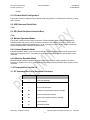
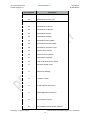
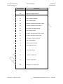
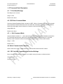
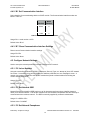
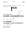
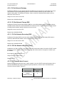
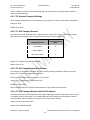
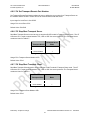
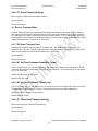
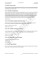
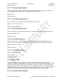
eS-WiFi Module
AT Command Set
User Manual
AT Command Set V2.00
Inventek Systems, Inc.
DOC-UM-20035-1.1
User Manual
eS-WiFi Module
eS-WiFi Module
‘embedded Serial-to-WiFi’
AT Command Set
Version 2.00
User Manual
Inventek Systems, Inc.
01/02/2012
Preliminary - Subject to change
eS-WiFi Module User Manual Version v1.2 01/02/2012
2
AT Command Set V2.00
Inventek Systems, Inc.
DOC-UM-20035-1.1
User Manual
eS-WiFi Module
Inventek System, Inc.
AT Command Set Copyright and Company Information
Contact Information:
Telephone: +1 978-667-1962
Fax : 1 978-667-1949
Location/Mailing Address:
Inventek Systems
2 Republic Road,
Billerica, MA 01862
Hours of Operation
Monday - Friday
U.S. EST 08:00 a.m. - 05:00 p.m
Send E-mail inquiries to:
Sales Support:
[email protected]
____
__
__ _ _____ _
___ / ___|
\ \
/ /(_)| ___|(_)
/ _ \\___ \ _____\ \ /\ / / | || |_
| |
| __/ ___) ||_____|\ V V / | || _| | |
\___||____/
\_/\_/
|_||_|
|_|
Inventek Systems
Inventing Your Tomorrow Today!
Copyright (c)2011
At Inventek Systems we pride ourselves in being a USA-based, full service GPS and Wi-Fi company.
While GPS modules and GPS antennas has been our primary focus, we are expanding to provide a full
line of Wi-Fi products. We also provide complete GPS services from consulting to custom design,
manufacturing and training.
For more information, call 978-667-1962 or email Sales Support or Technical support
Copyright ©2011 Inventek Systems
Technical support:
[email protected]
Preliminary - Subject to change
eS-WiFi Module User Manual Version v1.1 12/15/2011
3
AT Command Set V2.00
Inventek Systems, Inc.
DOC-UM-20035-1.1
User Manual
eS-WiFi Module
AT Command Set User Manual
Table of Contents
1. INTRODUCTION
7
1.1. SCOPE
1.2. SUPPORTED PRODUCT VERSIONS
1.3. AT COMMAND SET
1.3.1. Entering AT Commands
1.4. SUPPORTED CHARACTER SETS
7
7
7
7
8
2. HARDWARE INTERFACE AND MODULE OPERATION
8
2.1. RS-232 SERIAL COMMUNICATION
2.1.1. Data Mode
2.1.2. Flow Control
2.1.3. Supported Baud Rates
2.1.4. Default Serial Configuration
2.2. USB (UNIVERSAL SERIAL BUS)
2.3. SPI (SERIAL PERIPHERAL INTERFACE BUS)
2.4. MODULE OPERATION MODES
2.4.1. Human Readable Mode
2.4.2. Machine Readable Mode
8
8
8
8
9
9
9
9
9
9
3. AT COMMAND SET VERSION 2.0
9
3.1. AT COMMAND SET LIST OF SUPPORTED FUNCTIONS
9
4. AT COMMAND DETAIL DESCRIPTION
12
4.1. ‘?’ PRINT HELP MESSAGE
4.2. ‘$$$’ ENTER COMMAND MODE
4.3. ‘---’ EXIT COMMAND MODE
4.4. SELECT COMMUNICATION INTERFACE
4.4.1. ‘B0’ Activate Communication Interface Settings
4.4.2. ‘B1’ Set Communication Interface
4.4.3. ‘B?’ Show Communication Interface Settings
4.5. CONFIGURE NETWORK SETTINGS
4.5.1. ‘C0’ Join a Network
4.5.2. ‘C1’ Set Network SSID
4.5.3. ‘C2’ Set Network Passphrase
4.5.4. ‘C3’ Set Network Security Type
4.5.5. ‘C4’ Set Network DHCP
4.5.6. ‘C5’ Set Network IP Version
4.5.7. ‘C6’ Set Network IP Address
4.5.8. ‘C7’ Set Network IP Mask
4.5.9. ‘C8’ Set Network Gateway
4.5.10. ‘C9’ Set Network Primary DNS
4.5.11. ‘CA’ Set Network Secondary DNS
4.5.12. ‘CB’ Set Network Join Retry Count
12
12
12
12
12
13
13
13
13
13
13
14
14
15
15
15
16
16
16
16
Preliminary - Subject to change
eS-WiFi Module User Manual Version v1.2 01/02/2012
4
AT Command Set V2.00
Inventek Systems, Inc.
DOC-UM-20035-1.1
4.5.13. ‘CC’ Network Auto Connect
4.5.14. ‘CD’ Disconnect from Network
4.5.15. ‘C?’ Show Network Settings
4.6. SCAN FOR NETWORK ACCESS POINTS
4.6.1. ‘F0’ Scan for Network Access Points
4.6.2. ‘F1’ Set Scan Repeat Count
4.6.3. ‘F2’ Set Scan Delay
4.6.4. ‘F?’ Show Scan Settings
4.7. SOFTWARE INFORMATION
4.7.1. ‘I0’ Application Name
4.7.2. ‘I1’ Firmware Version
4.7.3. ‘I2’ Platform Software Version
4.7.4. ‘I3’ IP Stack Name and Version
4.7.5. ‘I4’ RTOS Name and Version
4.7.6. ‘I?’ Show Applications Information
4.8. TRANSPORT COMMUNICATION
4.8.1. ‘P0’ Activate Transport Settings
4.8.2. ‘P1’ Set Transport Protocol
4.8.3. ‘P2’ Set Transport Local Port Number
4.8.4. ‘P3’ Set Transport Remote Host Port IP Address
4.8.5. ‘P4’ Set Transport Remote Port Number
4.8.6. ‘P5’ Stop/Start Transport Server
4.8.7. ‘P6’ Stop/Start Transport Client
4.8.8. ‘P?’ Show Transport Settings
4.1. RECEIVE TRANSPORT DATA
4.9.1. ‘R0’ Read Transport Data
4.9.2. ‘R1’ Set Read Transport Packet Size (bytes)
4.9.3. ‘R2’ Set Read Transport Timeout (ms)
4.9.4. ‘R?’ Show Read Transport Settings
4.10. WRITE TRANSPORT DATA
4.10.1. ‘S0’ Write Transport Data
4.10.2. ‘S1’ Set Write Transport Packet Size (bytes)
4.10.3. ‘S2’ Set Write Transport Timeout (ms)
4.10.4. ‘S?” Show Write Transport Settings
4.11. PING IP TARGET ADDRESS
4.11.1. ‘T0’ Ping IP Target Address
4.11.2. ‘T1’ Set Ping Target Address
4.11.3. ‘T2’ Set Ping Repeat Count
4.11.4. ‘T3’ Set Ping Delay (ms)
4.11.5. ‘T?’ Show Ping Settings
4.12. CONFIGURE UART
4.12.1. ‘U0’ Activate UART Settings
4.12.2. ‘U1’ Set UART Comm Port
4.12.3. ‘U2’ Set UART Baud Rate
4.12.4. ‘U3’ Set UART Data Mode
4.12.5. ‘U4’ Set RX Timeout
Preliminary - Subject to change
User Manual
eS-WiFi Module
16
17
17
17
17
18
18
18
18
18
18
19
19
19
19
19
20
20
20
20
21
21
21
22
22
22
22
22
22
23
23
23
23
23
23
24
24
24
24
24
24
24
25
25
26
26
eS-WiFi Module User Manual Version v1.1 12/15/2011
5
AT Command Set V2.00
Inventek Systems, Inc.
DOC-UM-20035-1.1
4.12.6. ‘U5’ Set TX Timeout
4.12.7. ‘U?’ Show UART Setting
User Manual
eS-WiFi Module
26
26
5. EXAMPLE ES-WIFI MODULE AT COMMAND USAGE
27
5.1. ENTERING HUMAN READABLE COMMAND MODE
5.2. CHANGING THE BAUD RATE
5.3. FINDING ACCESS POINTS
5.4. JOIN NETWORK ACCESS POINT
5.5. PING A SYSTEM ON A NETWORK
5.6. TRANSMISSION CONTROL PROTOCO
5.6.1. TCP Server Set up and Data Transport
27
27
28
29
31
32
32
5.6.1.1. TCP Server Set Up
5.6.1.2. Read and Write TCP Data in Server Mode
32
32
5.6.2. TCP Client Setup and Data Transport
33
5.6.2.1. TCP Client Set Up
5.6.2.2. Read and Write TCP Data in Client Mode
33
34
5.6.3. UDP Server Set Up and Data Transport
35
5.6.3.1. UDP Server Set Up
5.6.3.2. Read and Write UDP Data in Server Mode
35
35
5.6.4. UDP Client Setup and Data Transport
36
5.6.4.1. UDP Client Set Up
5.6.4.2. Read and Write UDP Data in Client Mode
36
37
6. DOCUMENT REVISION HISTORY
39
Preliminary - Subject to change
eS-WiFi Module User Manual Version v1.2 01/02/2012
6
AT Command Set V2.00
Inventek Systems, Inc.
DOC-UM-20035-1.1
User Manual
eS-WiFi Module
1. Introduction
1.1. Scope
The scope of this document is to introduce users to Inventek Systems’ AT Command Set for the eS-WiFi
Module product, and to explain how to take advantage of the AT Command Set for WiFi Communications.
AT Command Usage in the User Manual is shown as
Usage: < AT Command > < optional ‘=’ > < data if ‘=’ is used > < Carriage Return (CR) >
or
< AT Command > < CR >
And default values are show as
Default: <AT Command>=<Value>
1.2. Supported Product Versions
2
This document is covers the following currently available eS-WiFi modules:
ISM4319-M3-L44-C
ISM4319-M3-L44-E
ISM4319-M3-L44-U
(Ceramic Antenna)
(Printed Micro-strip Antenna)
(U.FL Connector to external antenna)
1.3. AT Command Set
In the early 1980’s, Hayes Microcomputer Products, Inc. was one of the first modem manufactures to use
an ‘AT’ type Command Set to control operations of their modem products for communication over the
Plain Old Telephone Service (POTS).
Since then a number of products have been developed for communications that use the ‘AT Command
Set’ for device control.
‘AT’ is short for ‘AT’tention, and is used to get the attention of a device for set up and control of it’s
functions. Normally, following the ‘AT’ command would be other letters and numbers that would control
the functions associated with the command. For example, ‘ATDT1234567‘ means ATtention modem Dial
with Tone the number following the command, which in this case is 1234567.
Common practice today is to shorten the ‘AT’ command to just the function command, which using the
example above, the shorten command to dial using tone for a number would be DT1234567.
1.3.1. Entering AT Commands
As mentioned above, it is common practice to drop the ‘AT’ in front of a device control command and just
use the device control function command letters and number combinations. Inventek System has
adopted this method for controlling the functions of the eS-WiFi module. In addition, Inventek System has
added an ‘=’ to the command to delimit the command from its data. For example, the AT Command to
set the eS-WiFi module’s IP Address would be ‘C6=127.0.0.1’ instead of ‘ATC6=127.0.0.1.
Preliminary - Subject to change
eS-WiFi Module User Manual Version v1.1 12/15/2011
7
AT Command Set V2.00
Inventek Systems, Inc.
DOC-UM-20035-1.1
User Manual
eS-WiFi Module
Also, a number of AT Commands for eS-WiFi module only use a single letter or a single letter plus
number to execute the command. For instance, ‘?’ will return available help information on the eS-WiFi
module. While a ‘C0’ command would command the eS-WiFi module to joined a network.
The format for entering AT Commands is shown as follows:
< AT Command > < optional ‘=’ > < data if ‘=’ is used > < Carriage Return (CR) >
or
< AT Command > < CR >
All AT Commands must be followed by a <CR> to activate the command.
Empty string values for AT Commands are shown with ‘NONE’ in the User Manual.
1.4. Supported character sets
Currently, the eS-WiFi module only supports 8 bit ASCII. All AT Commands must be in capital letters;
however, data can contain both upper and letter case letters, and numbers.
Future support for binary data transfers to be added.
2. Hardware Interface and Module Operation
The eS-WiFi module supports RS-232 Serial Communications Universal Serial Bus (USB), and Serial
Peripheral Interface Bus (SPI). A Micro-Controller or System Host can easily interface up to the eS-WiFi
module using one of the support hardware interfaces.
The eS-WiFi module has two modes of operation: Human Readable Mode and Machine Readable Mode.
2.1. RS-232 Serial Communication
2.1.1. Data Mode
When the eS-WiFi module is interfaced serially, the serial interface needs to be configured for 8 bit data,
no parity, and one stop bit -- (8-n-1).
2.1.2. Flow Control
The eS-WiFi module doesn’t require or support Flow Control, so Flow Control should be ‘None’
2.1.3. Supported Baud Rates
The eS-WiFi module support the following serial baud rates:
1200
2400
4800
9600
19200
38400
57600
115200
230400
460800
Preliminary - Subject to change
eS-WiFi Module User Manual Version v1.2 01/02/2012
8
AT Command Set V2.00
Inventek Systems, Inc.
DOC-UM-20035-1.1
User Manual
eS-WiFi Module
921600
2.1.4. Default Serial Configuration
The eS-WiFi module is shipped with the default serial configuration of 115200 baud, 8 data bits, no party,
and 1 stop bits.
2.2. USB (Universal Serial Bus)
(TDB)
2.3. SPI (Serial Peripheral Interface Bus)
(TDB)
2.4. Module Operation Modes
The eS-WiFi module has two modes of operation, Human Readable Mode (verbose) and Machine
Readable Mode, that can be used to control the operation of the module. At power up, the eS-WiFi
module defaults to Machine Readable Mode. An AT command is used to put the eS-WiFi module into
Human Readable Mode or Machine Readable Mode.
2.4.1. Human Readable Mode
In Human Readable Mode, a user can interact with the module via the module’s built-in console and a
serial terminal program. All AT commands will return detail information related to the operation of the
command.
2.4.2. Machine Readable Mode
Machine Readable Mode is intended for direct control of the eS-WiFi module operation via a MicroController or System Host. All AT commands will return short, limited information about operation of the
command.
3. AT Command Set Version 2.0
3.1. AT Command Set List of Supported Functions
AT Command
?
$$$
Description
Print Help Message
Enter Command Mode
---
Exit Command mode
B0
Activate Communication Interface Settings
B1
Set Communication Interface
B?
Show Communication Interface Settings
C0
Join a Network
C1
Set Network SSID
Preliminary - Subject to change
eS-WiFi Module User Manual Version v1.1 12/15/2011
9
AT Command Set V2.00
Inventek Systems, Inc.
DOC-UM-20035-1.1
AT Command
User Manual
eS-WiFi Module
Description
C2
Set Network Passphrase
C3
Set Network Security Type
C4
Set Network DHCP Mode
C5
Set Network IP Version
C6
Set Network IP Address
C7
Set Network IP Mask
C8
Set Network Gateway
C9
Set Network Primary DNS
CA
Set Network Secondary DNS
CB
Set Network Join Retry Count
CC
Network Auto Connect
CD
Disconnect from Network
C?
Show Network Settings
F0
Scan for Network Access Points
F1
Set Scan Repeat Count
F2
Set Scan Delay (ms)
F?
Show Scan Settings
I0
Application Name
I1
Firmware Version
I2
Platform Software Version
I3
IP Stack Name and Version
I4
RTOS Name and Version
I?
Show Application Information
P0
Activate Transport Settings
P1
Set Transport Protocol
P2
Set Transport Local Port Number
P3
Set Transport Remote Host IP Address
Preliminary - Subject to change
eS-WiFi Module User Manual Version v1.2 01/02/2012
10
AT Command Set V2.00
Inventek Systems, Inc.
DOC-UM-20035-1.1
AT Command
User Manual
eS-WiFi Module
Description
P4
Set Transport Remote Port Number
P5
Stop/Start Transport Server
P6
Stop/Start Transport Client
P?
Show Transport Settings
R0
Read Transport Data
R1
Set Read Transport Packet Size (bytes)
R2
Set Read Transport Timeout (ms)
R?
Show Read Transport Settings
S0
Write Transport Data
S1
Set Write Transport Packet Size (bytes)
S2
Set Write Transport Timeout (ms)
S?
Show Write Transport Settings
T0
Ping Target Address
T1
Set Ping Target Address
T2
Set Ping Repeat Count
T3
Set Ping Delay (ms)
T?
Show Ping Settings
U0
Active UART Settings
U1
Set UART COMM Port
U2
Set UART BAUD Rate
U3
Set UART Data Mode
U4
Set UART RX Timeout (ms)
U5
Set UART TX Timeout (ms)
U?
Show UART Settings
Table 3.1: AT Command Set List
Preliminary - Subject to change
eS-WiFi Module User Manual Version v1.1 12/15/2011
11
AT Command Set V2.00
Inventek Systems, Inc.
DOC-UM-20035-1.1
User Manual
eS-WiFi Module
4. AT Command Detail Description
4.1. ‘?’ Print Help Message
Print Help menu to console.
Usage: ?<CR>
Default Value: None
4.2. ‘$$$’ Enter Command Mode
Command (Human Readable) Mode is entered via ‘$$$”. While in Command mode, all AT Commands
return detail text formatted information to the user when the command is executed. Command Mode is
helpful when debugging network interfaces or interaction with the eS-WiFi module.
Usage: $$$<CR>
Default Value: None
4.3. ‘---’ Exit Command Mode
Command Mode is exited via ‘---’, which places the eS-WiFi module in Machine Readable mode where
AT Commands generate short, limited coma delimited information on the execution of a command.
Machine mode is intended for Micro-Controller or Host System control of the eS-WiFi module.
Usage: ---<CR>
Default Value: ---
4.4. Select Communication Interface
Used to select SPI, UART, or USB interface for communication with the eS-WiFi module.
4.4.1. ‘B0’ Activate Communication Interface Settings
Store Communication Interface Settings to non-volatile memory for power on default selection.
Usage: B0 <CR>
Default Value: None
Preliminary - Subject to change
eS-WiFi Module User Manual Version v1.2 01/02/2012
12
AT Command Set V2.00
Inventek Systems, Inc.
DOC-UM-20035-1.1
User Manual
eS-WiFi Module
4.4.2. ‘B1’ Set Communication Interface
Select interface for communicating with the eS-WiFi module. The Communication Interface modes are
listed in Table 4.1.
Interface
Mode
Number
UART
0
SPI
1
USB
2
Table 4.1: Communication Interface Modes
Usage: B1=< mode number ><CR>
Default Value: B1=0
4.4.3. ‘B?’ Show Communication Interface Settings
Return current Communication Interface settings.
Usage: B?<CR>
Default Value: None
4.5. Configure Network Settings
Used to set up the network parameters needed to access a WiFi network.
4.5.1. ‘C0’ Join a Network
Using the user define parameters of SSID, Passphrase, Security Type, etc. attempt to join a WiFi network
for access. A successful Join, returns SSID and IP Address; otherwise, an error message is return. A
network can not be re-joined once the eS-WiFi module has joined a network without first closing the
current network connection.
Usage: C0<CR>
Default Value: None
4.5.2. ‘C1’ Set Network SSID
Network Service Set Identifier (SSID) can be up to 32 characters and is an unique identifier (network
name) for a wireless network. The eS-WiFi module must use the SSID, Passphrase and WiFi Security to
communicate with a wireless network. The SSID is normally supplied by a network administrator.
Usage: C1=<SSID><CR>
Default Value C1=NONE
4.5.3. ‘C2’ Set Network Passphrase
Preliminary - Subject to change
eS-WiFi Module User Manual Version v1.1 12/15/2011
13
AT Command Set V2.00
Inventek Systems, Inc.
DOC-UM-20035-1.1
User Manual
eS-WiFi Module
Network Passphrase can be up to 32 characters and is an unique security keyword for access to a
wireless network. The eS-WiFi module must use the Passphrase associated with the network SSID and
the WiFi Network Security to communicate with a wireless network. The Passphrase is normally supplied
by a network administrator.
Usage: C2=<Passphrase><CR>
Default Value: C2=NONE
4.5.4. ‘C3’ Set Network Security Type
Select the WiFi Network Security to use for communication with a WiFi network. Below is a list of WiFi
Security Modes. The eS-WiFi module must use one the WiFi Security modes with the associated SSID
and Passphrase to communicate with a wireless network. The WiFi Security is normally supplied by a
network administrator. The Network WiFi Security Modes are listed in Table 4.2.
WiFi Security
WiFi Security
Mode
Open
0
No WiFi Security
WEP
1
Wired Equivalent Privacy
WPA
2
WiFi Protected Access
WPA2
3
WiFi Protected Access 2
WPA + WPA2
4
WiFi Protected Access and
WiFi Protected Access 2
Description
Table 4.2: Network WiFi Security Modes
Usage: C3=<WiFi Security Modes><CR>
Default Value: C3=0
4.5.5. ‘C4’ Set Network DHCP
Dynamic Host Configuration Protocol (DHCP) is used to query a network for an available IP Address that
would be used for communications on the network. The eS-WiFi module can use DHCP or a user defined
IP Address. The eS-WiFi module must have an IP Address to communicate with a wireless network. The
Network DHCP Modes are listed in Table 4.3.
DHCP
DHCP Mode
Disabled
User supplied IP Address
0
Enabled
Network supplied IP Address
1
Table 4.3: Network DHCP Modes
Usage: C4=<DHCP Modes><CR>
Default Value: C4=1
Preliminary - Subject to change
eS-WiFi Module User Manual Version v1.2 01/02/2012
14
AT Command Set V2.00
Inventek Systems, Inc.
DOC-UM-20035-1.1
User Manual
eS-WiFi Module
4.5.6. ‘C5’ Set Network IP Version
Set Network IP Version is used to select between Internet Protocol Version 4 (IPV4) and Internet Protocol
Version 6 (IPV6). The IP Version must be set for correct operation of the eS-WiFi module on a wireless
network. The Network IP Version settings are listed in Table 4.4.
IP Version
IP Version
Mode
IPV4
0
IPV6
1
Table 4.4: Network IP Version Modes
Usage: C5=<IP Version Modes><CR>
Default Value C5=0
4.5.7. ‘C6’ Set Network IP Address
Set Network IP Address allows the user to define the IP Address that the eS-WiFi module will use on a
wireless network. If DHCP is disabled, the IP Address must be set to allow the eS-WiFi module to work
correctly on a wireless network. The IP Address must be entered in dotted-decimal notation, which is
defined as xxx.xxx.xxx.xxx for the network address.
If DHCP is enabled, the IP Address will be set by the wireless network on a network join.
Usage: C6=<xxx.xxx.xxx.xxx.><CR>
Default Value: 000.000.000.000
4.5.8. ‘C7’ Set Network IP Mask
Set Network IP Mask is user define value for the network net mask (subnetting of the network) used on
the WiFi Network. If DHCP is disabled, the net mask must be set to allow the eS-WiFi module to work
correctly on a wireless network The net mask must be entered in dotted-decimal notation, which is
defined as xxx.xxx.xxx.xxx.
if DHCP is enabled, the Net Mask will be set by the wireless network on a network join.
Usage: C7=<xxx.xxx.xxx.xxx><CR>
Default Value: 000.000.000.000
Preliminary - Subject to change
eS-WiFi Module User Manual Version v1.1 12/15/2011
15
AT Command Set V2.00
Inventek Systems, Inc.
DOC-UM-20035-1.1
User Manual
eS-WiFi Module
4.5.9. ‘C8’ Set Network Gateway
Set Network Gateway is a user define Gateway IP Address use by the devices on the network to access
other networks or as a default gateway when no other IP Address matches any other routes in the
network routing table. The Gateway IP Address must be entered in dotted-decimal notation, which is
defined as xxx.xxx.xxx.xxx.
Usage: C8=<xxx.xxx.xxx.xxx><CR>
Default Value: 000.000.000.000
4.5.10. ‘C9’ Set Network Primary DNS
Set Network Primary Domain Name System (DNS) is a user define address used for translating human
readable domain names into numerical identifiers for network devices. The Primary DNS must be entered
in dotted-decimal notation, which is defined as xxx.xxx.xxx.xxx.
Usage C9=<xxx.xxx.xxx.xxx><CR>
Default Value: 000.000.000.000
4.5.11. ‘CA’ Set Network Secondary DNS
Set Network Secondary DNS is used as a back up to the Primary DNS. The Secondary DNS must be
entered in dotted-decimal notation, which is defined as xxx.xxx.xxx.xxx.
Usage: CA=<xxx.xxx.xxx.xxx><CR>
Default Value: 000.000.000.000
4.5.12. ‘CB’ Set Network Join Retry Count
Set Network Join Retry Count is a user define value that controls the number of times the eS-WiFi module
will attempt to join a wireless network before stopping with a failure notice if the system is unable to join
the network.
Input range for Join Retries is 0 to 10.
Usage: CB=<Join Retries><CR>
Default Value: 5
4.5.13. ‘CC’ Network Auto Connect
Network Auto Connect allows the user to define weather or not the eS-WiFi module will attempt a Join a
wireless network after the system is powered up and operational, or after a reset. The Network Auto
Connect modes are listed in Table 4.5.
Auto Connect
Mode
Auto Connect
Disable
Network Auto-Join
Preliminary - Subject to change
0
eS-WiFi Module User Manual Version v1.2 01/02/2012
16
AT Command Set V2.00
Inventek Systems, Inc.
DOC-UM-20035-1.1
User Manual
eS-WiFi Module
Auto Connect
Mode
Auto Connect
Enable
Network Auto-Join
1
Table 4.5: Network Auto Connect Modes
Usage: CC=<Auto Connect Modes><CR>
Default Value: 0
4.5.14. ‘CD’ Disconnect from Network
To disconnect the eS-WiFi module from a wireless network, the AT Command ‘CD’ is used. ‘CD’ will
shutdown the network communications and clear the network IP Address, Net Mask, and Gateway
Address assigned to the eS-WiFi Module
Usage: CD<CR>
Default Value: None
4.5.15. ‘C?’ Show Network Settings
Return current Configured Network Settings.
Usage: C?<CR>
Default Value: None
4.6. Scan for Network Access Points
The eS-WiFi module can scan for available networks and return detail information about networks found
without having to join a network. The information return on the available networks includes SSID, BSSID,
RSSI, Data Rate, Network Type, Security, Radio Band, and Channel. The information return about
Network Access Points can be used in Joining one of the networks.
Scanning for Network Access Points is a very handy command for determining what wireless networks
are in listening range of the eS-WiFi module.
4.6.1. ‘F0’ Scan for Network Access Points
Find Networks can be used to scan for available networks and return information about the networks
found.
Usage: F0<CR>
Default Value: None
Preliminary - Subject to change
eS-WiFi Module User Manual Version v1.1 12/15/2011
17
AT Command Set V2.00
Inventek Systems, Inc.
DOC-UM-20035-1.1
User Manual
eS-WiFi Module
4.6.2. ‘F1’ Set Scan Repeat Count
Set Repeat Count is a user defined value that controls the number of times to scan for Network Access
Points.
Input range for Set Scan Repeat Count is 0 to 255.
Usage: F1=<Set Scan Repeat Count><CR>
Default Value: 0
4.6.3. ‘F2’ Set Scan Delay
Set Scan Delay is a user defined value that set the amount of time in milliseconds to wait between scans
for Network Access Points.
Input range for Set Scan Delay is 0 to 5000, which represents the delay in milliseconds.
Usage: F2=<Set Scan Delay><CR>
Default Value: 1000
4.6.4. ‘F?’ Show Scan Settings
Return current Scan Settings.
Usage: F?<CR>
Default Value: None
4.7. Software Information
Information about the AT Command application that includes Firmware Version, Wiced Version, IP Stack
Name and Version, RTOS Name and Version can be access using the following AT Commands.
4.7.1. ‘I0’ Application Name
Information about the Application Name running on the eS-WiFi Module can be returned using the AT
Command ‘I0’.
Usage: I0<CR>
Default Value: None
4.7.2. ‘I1’ Firmware Version
Information about the Application Firmware Version running on the eS-WiFi Module can be returned using
the AT Command ‘I1’.
Usage: I1<CR>
Default Value: None
Preliminary - Subject to change
eS-WiFi Module User Manual Version v1.2 01/02/2012
18
AT Command Set V2.00
Inventek Systems, Inc.
DOC-UM-20035-1.1
User Manual
eS-WiFi Module
4.7.3. ‘I2’ Platform Software Version
Information about WiFi Platform Software Version running on the eS-WiFi Module can be returned using
the AT Command ‘I2’.
Usage: I2<CR>
Default Value: None
4.7.4. ‘I3’ IP Stack Name and Version
Information about the IP Stack and Version running on the eS-WiFi Module can be returned using the AT
Command ‘I3’.
Usage: I3<CR>
Default Value: None
4.7.5. ‘I4’ RTOS Name and Version
Information about the RTOS and Version running on the eS-WiFi Module can be returned using the AT
Command ‘I4’.
Usage: I4<CR>
Default Value: None
4.7.6. ‘I?’ Show Applications Information
The AT Command ‘I?’ will return Application, Firmware, Platform, IP Stack, and FreeRTOS information.
Usage: I?<CR>
Default Value: None
4.8. Transport Communication
Transmission Control Protocol (TCP) and User Datagram Protocol (UDP) are used for point to point or
port to port communications on a network. TCP is a guarantee port to port communication protocol that is
used to insure data is transfer error free between a server and client. UDP is consider to be faster than
TCP for the movement of data over a network; however, UDP does not guarantee the delivery of data
between a server and a client. UDP lite is UDP with the partial removable of checksums which may
improve network data movement performance but may be more prone to data errors.
The eS-WiFi module supports TCP, UDP, and UDP lite for port to port communication.
The eS-WiFi module can be configured as a server or client on a network for TCP/UDP communication.
In Transport server mode, the eS-WiFi module will wait in the background for connection requests. Once
a network device request a connection to the server, the server will enter a mode were data can be
requested by a client and data delivered to a client.
The eS-WiFi module can also be configured as a client for TCP/UDP communications to make requests
to a Transport server on the wireless network.
Preliminary - Subject to change
eS-WiFi Module User Manual Version v1.1 12/15/2011
19
AT Command Set V2.00
Inventek Systems, Inc.
DOC-UM-20035-1.1
User Manual
eS-WiFi Module
If UDP or UDP lite is used, it recommended that the user develop their on packet numbering and error
checking for data transfers.
4.8.1. ‘P0’ Activate Transport Settings
Store Transport configurations to non-volatile memory for power on or after a reset default configuration.
Usage: P0 <CR>
Default Value: None
4.8.2. ‘P1’ Set Transport Protocol
Set Transport Protocol allows the user to enable selection of ether TCP, UDP, or UDP Lite for network
port to port communications. The Transport Protocols modes are listed in Table 4.6.
Transport Protocol
Transport Protocol
Mode
TCP Enabled
0
UDP Enabled
1
UDP Lite Enabled
2
Table 4.6: Transport Protocol Modes
Usage: P1=<Transport Protocol Modes><CR>
Default Value: P1=0
4.8.3. ‘P2’ Set Transport Local Port Number
Set Transport Local Port Number allows the user to define the local port that the eS-WiFi module will
listen on for Transport communication connections.
Input range for Transport Local Port Number is 0 to 65535.
Usage: P2=<Transport Local Port Number><CR>
Default Value: P2=5024
Refer to documentation on TCP/UDP communications for pre-defined port information.
4.8.4. ‘P3’ Set Transport Remote Host Port IP Address
Set Transport Remote Host IP Address is a user define address that eS-WiFi module will used to contact
a Transport server on the network. The Transport Remote Host IP Address must be entered in dotteddecimal notation, which is defined as xxx.xxx.xxx.xxx for the network address.
Usage: P3=<xxx.xxx.xxx.xxx><CR>
Default Value: 000.000.000.000
Preliminary - Subject to change
eS-WiFi Module User Manual Version v1.2 01/02/2012
20
AT Command Set V2.00
Inventek Systems, Inc.
DOC-UM-20035-1.1
User Manual
eS-WiFi Module
4.8.5. ‘P4’ Set Transport Remote Port Number
Set Transport Remote Port Number allows the user to define the port number for a Transport Server on
the network that the eS-WiFi module will use to communications with that server.
Input range for Local Port is 0 to 65535.
Usage: P4=<Local Port><CR>
Default Value: P4=5025
4.8.6. ‘P5’ Stop/Start Transport Server
Stop/Start Transport Server is used to stop or start the eS-WiFi module’s Transport Server mode. The AT
Command ‘P1’ is used to select between TCP, UDP or UDP Lite server protocols. The Transport Server
modes are listed in Table 4.7.
Transport Server
Transport Server
Mode
Server Disable
0
Server Enable
1
Figure 4.7: Transport Server Modes
Usage: P5=<Transport Server Modes><CR>
Default Value: P5=0
4.8.7. ‘P6’ Stop/Start Transport Client
Stop/Start Transport Client is used to stop or start the eS-WiFi module’s Transport Client mode. The AT
Command ‘P1’ is used to select between TCP, UDP or UDP Lite server protocols. The Transport Server
modes are listed in Table 4.8.
Transport Client
Transport Client
Mode
Client Disable
0
Client Enable
1
Figure 4.8: Transport Server Mode
Usage: P6=<Transport Client Modes><CR>
Default Value: P5=0
Preliminary - Subject to change
eS-WiFi Module User Manual Version v1.1 12/15/2011
21
AT Command Set V2.00
Inventek Systems, Inc.
DOC-UM-20035-1.1
User Manual
eS-WiFi Module
4.8.8. ‘P?’ Show Transport Settings
Return current Transport Communication Settings.
Usage: P?<CR>
Default Value: None
4.1. Receive Transport Data
Once the Transport Protocol has been defined and either the server or client mode has been enabled,
Data can be received from a connected server or client using the AT Command ‘R0’ with AT Command
‘R1‘ setting the size of data to read from the transport protocol stack. For TCP data, multiple reads may
been needed to return all of the available data; however, for UDP, data received greater than the number
of bytes defined by the AT Command ‘R1’ will be lost.
4.9.1. ‘R0’ Read Transport Data
Available receive data is read using the AT Command ‘R0’. ‘R0’ reads the transport buffer for AT
Command ‘R1’ size bytes. Multiple reads may been needed to read all of the available TCP data. UDP
data received greater than the bytes size defined by R1 will be lost.
Usage: R0<CR>
Default Value: None
4.9.2. ‘R1’ Set Read Transport Packet Size (bytes)
The AT Command ‘R1’ is a user defined value for the packet size of data to return a data read. The AT
Command ‘R1’ should be set before a performing AT Command ‘R0’. The input range for AT Command
‘R1’ is 0 to 1200 bytes.
Usage: R1=<Data Packet Size><CR>
Default Value: R1=1200
4.9.3. ‘R2’ Set Read Transport Timeout (ms)
The AT Command ‘R2’ is a user defined value for the amount of time in milliseconds to wait on the Read
Transport Data AT Command ‘R2’ to finish. The input range for R2 is 0 to 30000 milliseconds.
Usage: R2=<Read Transport Timeout><CR>
Default Value: R1=5000
4.9.4. ‘R?’ Show Read Transport Settings
Return current Receive Transport Data Settings.
Usage: R?<CR>
Default Value: None
Preliminary - Subject to change
eS-WiFi Module User Manual Version v1.2 01/02/2012
22
AT Command Set V2.00
Inventek Systems, Inc.
DOC-UM-20035-1.1
User Manual
eS-WiFi Module
4.10. Write Transport Data
Once the Transport Protocol has been define and either the server or client mode has been enabled, data
can be written to a connected Transport Server or Client using the AT Command ‘S0’ with AT Command
‘S1‘ defining the size of data to write.
4.10.1. ‘S0’ Write Transport Data
The At Command ‘S0’ is used to write data to a Transport Server or Client. The size of the data to write is
defined via the AT Command ‘S1’. After the AT Command ‘S0’ is entered any data writing to eS-WiFi
module selected communicating interface will be sent to a connected Transport Server or Client. Once
the number bytes defined by AT Command ‘S1’ have been sent, the eS-WiFi module will return back to
the AT Command mode waiting for the next ‘AT Command’. If more bytes are written to the eS-WiFi
module then are defined by the AT Command ‘S1’, the data will be lost and error message will be
returned on the excess data written to the eS-WiFi module selected communication interface.
Usage: S0<CR>
4.10.2. ‘S1’ Set Write Transport Packet Size (bytes)
AT Command ‘S1’ is used to define the packet size of data to write to a connect Transport Server or
Client. The AT Command ‘S1’ should be set before a performing AT Command ‘S0’.
Usage: S1=<Data Packet Size><CR>
Default Value: S1=1200
4.10.3. ‘S2’ Set Write Transport Timeout (ms)
The AT Command ‘S2’ is a user defined value for the amount of time in milliseconds to wait on the Write
Transport Data AT Command ‘R2’ to finish. The input range for S2 is 0 to 30000 milliseconds.
Usage: S2=<Write Transport Timeout><CR>
Default Value: S1=5000
4.10.4. ‘S?” Show Write Transport Settings
Return current Write Transport Data Settings.
Usage: S?<CR>
Default Value: None
4.11. Ping IP Target Address
Ping is a network utility for testing the reachability of hosts on a network. Ping will measure the round-trip
time to a host or return a timeout if the host is not reachable.
Preliminary - Subject to change
eS-WiFi Module User Manual Version v1.1 12/15/2011
23
AT Command Set V2.00
Inventek Systems, Inc.
DOC-UM-20035-1.1
User Manual
eS-WiFi Module
4.11.1. ‘T0’ Ping IP Target Address
The AT Command ‘T0’ will Ping a remote host returning the round-trip time or a timeout message. The
host IP Address used by Ping must be set up by using the AT Command ‘T1’.
Usage: T0<CR>
Default Value: None
4.11.2. ‘T1’ Set Ping Target Address
The AT Command ‘T1’ is used to set the IP Address of the host to Ping.
Usage T1=<xxx.xxx.xxx.xxx><CR>
Default Value: 000.000.000.000
4.11.3. ‘T2’ Set Ping Repeat Count
The AT Command ‘T2’ is used to define the number of times to repeat a Ping of a host on the network.
Usage T2=<Repeats><CR>
Default Value: T2=0
4.11.4. ‘T3’ Set Ping Delay (ms)
The AT Command ‘T3’ is used to define the amount of time to wait between Pinging a host on the
network. The amount of time to wait is defined in milliseconds and is limited to the range of 0 to 5000.
Usage T3=<delay in ms><CR>
Default Value: T3=0
4.11.5. ‘T?’ Show Ping Settings
Return current Ping Settings.
Usage: T?<CR>
Default Value: None
4.12. Configure UART
The eS-WiFi module can be configured to use it’s serial interface for communications with a host
computers or a terminal console programs. Currently, the only UART Configuration mode for the eS-WiFi
module is the serial interface, which is set to 8 data bits, no parity, one stop bits. The eS-WiFi module
can support baud rates from 1200 to 921600 baud. The AT Command ‘U2’ is used to set the baud rate.
The eS-WiFi module interface can also be set up in ASCII or Binary mode for data. In addition, the eSWiFi module can be configured to generate timeout messages on the serial communications.
4.12.1. ‘U0’ Activate UART Settings
Preliminary - Subject to change
eS-WiFi Module User Manual Version v1.2 01/02/2012
24
AT Command Set V2.00
Inventek Systems, Inc.
DOC-UM-20035-1.1
User Manual
eS-WiFi Module
The AT Command ‘U0’ is used to store the current eS-WiFi module UART settings in non-volatile memory
for power on or after a reset for automatic configuration of the UART.
Usage: U0<CR>
Default Value: None
4.12.2. ‘U1’ Set UART Comm Port
Currently, the eS-WiFi module only support UART for Micro-Controlling or Host System interfacing.
Future versions of the eS-WiFi module will support SPI and UART. Table 4.9 list the eS-Wfif Module
Comm Port modes.
Comm Port
Comm Port Mode
UART
0
USB
1
Table 4.9: Comm Port Modes
Usage: U1=<Comm Port Modes><CR>
Default Value: U1=0
4.12.3. ‘U2’ Set UART Baud Rate
The AT Command ‘U2’ is used to set the baud rate for the Comm Port selected using the AT Command
‘U1’. Table 4.10 list the available eS-WiFi module baud rates.
Baud Rates
1200
2400
4800
9600
19200
38400
57600
115200
230400
460800
921600
Table 4.10: Baud Rates
Preliminary - Subject to change
eS-WiFi Module User Manual Version v1.1 12/15/2011
25
AT Command Set V2.00
Inventek Systems, Inc.
DOC-UM-20035-1.1
User Manual
eS-WiFi Module
Usage: U2=<Baud Rate><CR>
Default Value: U2=115200
4.12.4. ‘U3’ Set UART Data Mode
The eS-WiFi module system interface can be set up for ASCII or Binary data modes. Table 4.11 list the
UART Data modes.
Data
Data Mode
ASCII
0
Binary
1
Table 4.11: UART Data Modes
Usage: U3=<Data Modes><CR>
Default Value: U3=0
4.12.5. ‘U4’ Set RX Timeout
<TDB>
4.12.6. ‘U5’ Set TX Timeout
<TDB>
4.12.7. ‘U?’ Show UART Setting
Return current UART Configuration.
Usage: U?<CR>
Default Value: None
Preliminary - Subject to change
eS-WiFi Module User Manual Version v1.2 01/02/2012
26
AT Command Set V2.00
Inventek Systems, Inc.
DOC-UM-20035-1.1
User Manual
eS-WiFi Module
5. Example eS-WiFi Module AT Command Usage
This section of the eS_WiFi Module User Manual covers example usage of the AT Command Set. Area
covered are Changing the Baud Rate, Scanning for Access Points, Joining Networks, transferring data
via Transmission Control Protocol using TCP and UDP.
5.1. Entering Human Readable Command Mode
The eS-WiFi Module supports a Human Readable Command Mode for console interaction with the ATCommand set. For the AT Command usage examples that follow, the Human Readable Command Mode
will be used. Sending the AT Command ‘$$$’ at the console prompt will put the eS-WiFi Module in
human readable mode. Sending the AT Command ‘---‘ will take the eS-WiFi Module out of Human
Readable mode and back into Machine Readable Mode, which is the default console mode for the eSWiFI Module.
Entering Human Readable Mode example:
>$$$
Entering CMD mode …
OK
>
5.2. Changing The Baud Rate
One of the first things that may be useful when using the eS-WiFi Module is to up the data rate of the eSWiFi Module serial interface for faster interaction with the console and data transfer.
Check Current Baud Rate:
>U?
Communication Port:
Baud Rate:
Data Width:
Parity:
Stop Bits:
Mode:
RX Timeout:
TX Timeout:
OK
>
UART
115200
8 bit
NONE
1
ASCII
0 ms
0 ms
Set New Baud:
>U2=921600
OK
>
Activate Baud Change:
>U0
At this point the eS-WiFi Module will expect a faster or slower baud depending on the baud used for U2.
The next step is to change the baud rate of the system to continue communicating with the eS-WiFI
Module. After changing the System baud, sending a <CR> should return the console prompt ‘>’, If not
reset the eS-WiFi Module and retry changing the baud.
Check Baud Rate After Change:
Preliminary - Subject to change
eS-WiFi Module User Manual Version v1.1 12/15/2011
27
AT Command Set V2.00
Inventek Systems, Inc.
>U?
Communication Port:
Baud Rate:
Data Width:
Parity:
Stop Bits:
Mode:
RX Timeout:
TX Timeout:
OK
>
DOC-UM-20035-1.1
User Manual
eS-WiFi Module
UART
921600
8 bit
NONE
1
ASCII
0 ms
0 ms
5.3. Finding Access Points
The first steps in joining a network is to determining available Access Points in the listening range of the
eS-WiFi Module. The eS-WiFi Module AT Command Set supports functions for finding Access Points.
The AT Command for finding Access Points can be used without joining a network.
Find Access Points:
> F0
Waiting for scan results...
#001 SSID
: mars
BSSID
: CC:33:CC:99:39:00
RSSI
: -39dBm
Max Data Rate : 54.0 Mbits/s
Network Type : Infrastructure
Security
: WPA2 AES
Radio Band
: 2.4GHz
Channel
: 2
#002 SSID
: jupiter
BSSID
: EE:99:FF:AA:DD:00
RSSI
: -90dBm
Max Data Rate : 54.0 Mbits/s
Network Type : Infrastructure
Security
: WPA2 AES
Radio Band
: 2.4GHz
Channel
: 1
#003 SSID
: saturn
BSSID
: FF:11:00:55:CC:EE
RSSI
: -90dBm
Max Data Rate : 54.0 Mbits/s
Network Type : Infrastructure
Security
: WEP
Radio Band
: 2.4GHz
Channel
: 6
#004 SSID
: uranus
BSSID
: 33:44:99:44:11:CC
RSSI
: -94dBm
Max Data Rate : 54.0 Mbits/s
Network Type : Infrastructure
Security
: WPA2 AES
Radio Band
: 2.4GHz
Channel
: 11
End of scan results
OK
>
If needed, the eS-WiFi Module can be set up to scan a number of times for Access Points. This mode
can be helpful during set up or debug on a network. The example below sets up the eS-WiFi Module to
run 5 Access Point scans.
Preliminary - Subject to change
eS-WiFi Module User Manual Version v1.2 01/02/2012
28
AT Command Set V2.00
Inventek Systems, Inc.
DOC-UM-20035-1.1
User Manual
eS-WiFi Module
> F1=5
OK
>
> F0
Waiting for scan results...
... (returned data)
End of scan results
Waiting for scan results...
... (returned data)
End of scan results
Waiting for scan results...
... (returned data)
End of scan results
Waiting for scan results...
... (returned data)
End of scan results
Waiting for scan results...
... (returned data)
End of scan results
OK
>
The eS-WiFi Module can also be set up using an AT Command to delay between scans. The delay is set
in milliseconds. The time range for delay is 0 to 5000 milliseconds.
Delay one second between scans:
> F2=1000
OK
>
Check current Find settings:
> F?
Scan Repeats:
Scan Delay in ms:
OK
>
10
1000
5.4. Join Network Access Point
To join a Network Access Point, the SSID, the PASSWORD, the Security Mode, and the IP Address
mode (DHCP or locally assigned IP Address) must be set. See your network administrator for information
needed to accessing Access Points on your network.
Using the information returned from previous network scan (F0) and network information supplied by the
Network Administrator, the eS-WiFi module can be configured to join an Access Point on the Network.
The following example shows how to join an Access Point using DHCP; however, a locally define IP
Address can also be used. Refer to the sections 4.5.5, 4.5.7, and 4.5.8 on setting a local IP Address for
the eS-WiFi module.
Set SSID for Access Point:
> C1=mars
Preliminary - Subject to change
eS-WiFi Module User Manual Version v1.1 12/15/2011
29
AT Command Set V2.00
Inventek Systems, Inc.
DOC-UM-20035-1.1
User Manual
eS-WiFi Module
Ok
>
Set Password for Access Point:
> C2=PASSWORD
OK
>
Set Security Mode (WPA2 AES) for Access Point:
> C3=3
OK
>
Set eS-WiFi Module IP Address via DHCP:
> C4=1
OK
>
Check Network Join settings before joining Access Point:
> C?
SSID:
PSWD:
SECURITY:
DHCP:
IP:
IP ADDR:
MASK:
GW ADDR:
DNS1:
DNS2:
Join Retries:
Auto Connect:
Status:
OK
>
mars
PASSWORD
WPA2 AES
Enabled
IPV4
0.0.0.0
0.0.0.0
0.0.0.0
0.0.0.0
0.0.0.0
5
0
Not Connected
Join Network Access Point mars, using PASSWORD, WPA2 AES, and DHCP:
> C0
Joining : mars
Successfully joined : mars
Obtaining IP address via DHCP
Network ready IP: 192.168.1.117
OK
>
Check Network Join Settings after joining Access Point:
> C?
SSID:
PSWD:
SECURITY:
DHCP:
IP:
IP ADDR:
MASK:
GW ADDR:
DNS1:
mars
PASSWORD
WPA2 AES
Enabled
IPV4
192.168.1.117
255.255.255.0
192.168.1.1
0.0.0.0
Preliminary - Subject to change
eS-WiFi Module User Manual Version v1.2 01/02/2012
30
AT Command Set V2.00
Inventek Systems, Inc.
DNS2:
Join Retries:
Auto Connect:
Status:
OK
>
DOC-UM-20035-1.1
User Manual
eS-WiFi Module
0.0.0.0
5
0
Connected
5.5. Ping a System on a Network
From time to time there is a need to Ping a system on a network or Ping a system while debugging a
connection on the network. The eS-WiFi module can be configured to Ping systems on a network. To
Ping a system on a network from the eS-WiFi Module, the IP Address of the system must be set up. In
addition to setting up IP Address for the system to ping, the number of times to perform the Ping and the
delay between Pings can be set. Assuming that eS-Wifi Module has already joined to a network, the
following steps will ping a system on the network.
Set Ping IP Address to 192.168.1.90 for a system on the Network:
> T1=192.168.1.90
OK
>
Set Ping Repeats to 5:
> T2=5
OK
>
Set Ping Delay to 500 milliseconds:
> T3=500
OK
>
Check Ping Settings:
> T?
Ping Target Address:
Ping Repeats:
Ping Delay:
OK
>
192.168.1.90
5
500 ms
Ping 192.168.1.90 on the network for five times with a 500 millisecond delay between pings:
> T0
Pinging: 192.168.1.90
Ping Reply 32ms
Pinging: 192.168.1.90
Ping Reply 5ms
Pinging: 192.168.1.90
Ping Reply 3ms
Pinging: 192.168.1.90
Ping Reply 4ms
Pinging: 192.168.1.90
Ping Reply 6ms
OK
>
Preliminary - Subject to change
eS-WiFi Module User Manual Version v1.1 12/15/2011
31
AT Command Set V2.00
Inventek Systems, Inc.
DOC-UM-20035-1.1
User Manual
eS-WiFi Module
5.6. Transmission Control Protoco
To move data across a network, Transmission Control Protocol is often used. The eS-WiFi Module can be
configured to be a Server or Client on a network for Transmission Control Protocol communications.
Also, the eS-WiFi Module supports TCP and UDP protocols for data transfer. The examples that follow
show TCP and UDP Server, and TCP and UDP Client operational modes of the eS-WiFi module. The
following examples also assume that Transmission Control Protocol software is used on the remote
Server or remote Client system and that a port number has been set up for use.
5.6.1. TCP Server Set up and Data Transport
The first step in setting up the eS-WiFi Module to be a TCP server on the Network, assuming the eS-WiFi
has been joined to a Network, is to set the protocol mode, followed by enabling the TCP server mode.
Once the eS-Wifi Module is in TCP server mode, data can then be written to and read from a remote
client on the network.
5.6.1.1. TCP Server Set Up
Set protocol to TCP:
> P1=0
OK
Set local TCP Port Number to 5024:
> P2=5024
OK
>
Enable TCP Server mode (the eS-WiFi Module will wait for a connection from a remote Client):
> P5=1
TCP Task set up
OK
> Waiting on TCP connection ...
> Accepted TCP connection from 192.168.1.107 on port 5024
>
Check TCP Server Mode Configuration:
> P?
Transport Protocol:
Client IP ADDR:
Local Port:
Remote Host IP ADDR:
Remote Host Port:
TCP Server Enabled:
UDP Server Enabled:
OK
>
TCP
192.168.1.107
5024
0.0.0.0
5025
Yes
No
5.6.1.2. Read and Write TCP Data in Server Mode
The eS-WiFi Module can read and write data over the network using Transmission Control Protocol. To
aid in moving data over the network, the eS-WiFi Module’s AT Command Set has commands for setting
Preliminary - Subject to change
eS-WiFi Module User Manual Version v1.2 01/02/2012
32
AT Command Set V2.00
Inventek Systems, Inc.
DOC-UM-20035-1.1
User Manual
eS-WiFi Module
the Packet Size and for setting the Timeouts for data movement. For TCP communications, multiple
reads may be needed to read all available data received. If no data is available, the read will timeout.
Set 1200 byte packet size for Read (range 1 to 1200):
> R1=1200
OK
>
Set five second timeout for Read in milliseconds (range 0 to 5000):
> R2=5000
Check Read Configuration:
> R?
Number of TCP/UPD bytes to receive per read:
TCP/UPD receive timeout:
OK
>
1200
5000 ms
Perform Read of Remote Client:
> R0
testing... 1234567890
OK
>
Write data to Remote Client:
> S0
0123456789
timeout detected... bytes sent 10
OK
>
The timeout was detected because the packet size was set to 1200 bytes, but only 10 bytes were written
to the remote client. After a 5000 millisecond delay and no further data, the 10 bytes were sent.
5.6.2. TCP Client Setup and Data Transport
The first step in setting up the eS-WiFi Module to be a client on a Network, assuming the eS-WiFi has
been joined to a Network, is to set the protocol mode, the remote port number, and remote server IP
Address. Once the eS-Wifi Module has been set up as a client for TCP data transfer, data can then be
written and read from a remote server on the network.
5.6.2.1. TCP Client Set Up
Set protocol to TCP:
> P1=0
OK
Set remote Server IP Address:
> P3=192.168.1.110
OK
Preliminary - Subject to change
eS-WiFi Module User Manual Version v1.1 12/15/2011
33
AT Command Set V2.00
Inventek Systems, Inc.
DOC-UM-20035-1.1
User Manual
eS-WiFi Module
Set remote TCP Port Number to 5025:
> P4=5025
OK
>
Enable TCP Client mode:
> P6=1
Connecting to 192.168.1.110
OK
>
Once the TCP Client mode AT Command returns to the console, a connection has been established with
a remote server or an error message will be generated on a connection failure.
Check TCP Client Mode Configuration:
> P?
Transport Protocol:
Client IP ADDR:
Local Port:
Remote Host IP ADDR:
Remote Host Port:
TCP Server Enabled:
UDP Server Enabled:
OK
>
UDP
0.0.0.0
5024
192.168.1.110
5025
NO
No
5.6.2.2. Read and Write TCP Data in Client Mode
The eS-WiFi Module can read and write data over the network using Transmission Control Protocol. To
aid in moving data over the network, the eS-WiFi Module’s AT Command Set has commands for setting
the Packet Size and for setting the Timeouts for data movement. For TCP communications, multiple
reads may be needed to read all available data received. If no data is available, the read will timeout.
Set 1200 byte packet size for Read:
> R1=1200
OK
>
Set five second timeout for Read in milliseconds:
> R2=5000
Check Read Configuration:
> R?
Number of TCP/UPD bytes to receive per read:
TCP/UPD receive timeout:
OK
>
1200
5000 ms
Perform Read of Remote Client:
> R0
testing... 1234567890
OK
Preliminary - Subject to change
eS-WiFi Module User Manual Version v1.2 01/02/2012
34
AT Command Set V2.00
Inventek Systems, Inc.
DOC-UM-20035-1.1
User Manual
eS-WiFi Module
>
Write data to Remote Client:
> S0
0123456789
timeout detected... bytes sent 10
OK
>
The timeout was detected because the packet size was set to 1200 bytes, but only 10 bytes were written
to the remote client. After a 5000 millisecond delay and no further data, the 10 bytes were sent.
5.6.3. UDP Server Set Up and Data Transport
The first step in setting up the eS-WiFi Module to be a UDP server on the Network, assuming the eS-WiFi
has been joined to a Network, is to set the protocol mode, followed by enabling the UDP server mode.
Once the eS-Wifi Module is in UDP server mode, data can then be written to and read from a remote
client on the network.
5.6.3.1. UDP Server Set Up
Set protocol to UDP:
> P1=1
OK
Set local UDP Port Number to 5024:
> P2=5024
OK
>
Enable UDP Server mode (the eS-WiFi Module will wait for a connection from a remote Client):
> P5=1
UDP Task set up
OK
> Waiting on UDP connection ...
> Accepted UDP connection from 192.168.1.110 on port 5024
>
Check UDP Server Mode Configuration:
> P?
Transport Protocol:
Client IP ADDR:
Local Port:
Remote Host IP ADDR:
Remote Host Port:
TCP Server Enabled:
UDP Server Enabled:
OK
>
UDP
192.168.1.110
5024
0.0.0.0
5025
No
Yes
5.6.3.2. Read and Write UDP Data in Server Mode
Preliminary - Subject to change
eS-WiFi Module User Manual Version v1.1 12/15/2011
35
AT Command Set V2.00
Inventek Systems, Inc.
DOC-UM-20035-1.1
User Manual
eS-WiFi Module
The eS-WiFi Module can read and write data over the network using Transmission Control Protocol. To
aid in moving data over the network, the eS-WiFi Module’s AT Command Set has commands for setting
the Packet Size and for setting the Timeouts for data movement. For UDP communications, the number
bytes sent to the server must match the number bytes to read -- any additional data sent to the server
may be lost.
Set 1200 byte packet size for Read (range 1 to 1200):
> R1=1200
OK
>
Set five second timeout for Read in milliseconds (range 0 to 5000):
> R2=5000
Check Read Configuration:
> R?
Number of TCP/UPD bytes to receive per read:
TCP/UPD receive timeout:
OK
>
1200
5000 ms
Perform Read of Remote Client:
> R0
testing... 1234567890
OK
>
Write data to Remote Client:
> S0
0123456789
timeout detected... bytes sent 10
OK
>
The timeout was detected because the packet size was set to 1200 bytes, but only 10 bytes were written
to the remote client. After a 5000 millisecond delay and no further data, the 10 bytes were sent.
5.6.4. UDP Client Setup and Data Transport
The first step in setting up the eS-WiFi Module to be a client on a Network, assuming the eS-WiFi has
been joined to a Network, is to set the protocol mode, the remote port number, and remote server IP
Address. Once the eS-Wifi Module has been set up as a client for UDP data transfer, data can then be
written and read from a remote server on the network.
5.6.4.1. UDP Client Set Up
Set protocol to UDP:
> P1=0
OK
Set remote Server IP Address:
Preliminary - Subject to change
eS-WiFi Module User Manual Version v1.2 01/02/2012
36
AT Command Set V2.00
Inventek Systems, Inc.
DOC-UM-20035-1.1
User Manual
eS-WiFi Module
> P3=192.168.1.110
OK
Set remote UDP Port Number to 5025:
> P4=5025
OK
>
Enable UDP Client mode:
> P6=1
Connecting to 192.168.1.110
OK
>
Once the UDP Client mode AT Command returns to the console, a connection has been established with
a remote server or an error message will be generated on a connection failure.
Check UDP Client Mode Configuration:
> P?
Transport Protocol:
Client IP ADDR:
Local Port:
Remote Host IP ADDR:
Remote Host Port:
TCP Server Enabled:
UDP Server Enabled:
OK
>
UDP
0.0.0.0
5024
192.168.1.110
5025
NO
No
5.6.4.2. Read and Write UDP Data in Client Mode
The eS-WiFi Module can read and write data over the network using Transmission Control Protocol. To
aid in moving data over the network, the eS-WiFi Module’s AT Command Set has commands for setting
the Packet Size and for setting the Timeouts for data movement. For UDP communications, the number
bytes sent to the server must match the number bytes to read -- any additional data sent to the server
may be lost.
Set 1200 byte packet size for Read:
> R1=1200
OK
>
Set five second timeout for Read in milliseconds:
> R2=5000
Check Read Configuration:
> R?
Number of TCP/UPD bytes to receive per read:
TCP/UPD receive timeout:
OK
>
Preliminary - Subject to change
1200
5000 ms
eS-WiFi Module User Manual Version v1.1 12/15/2011
37
AT Command Set V2.00
Inventek Systems, Inc.
DOC-UM-20035-1.1
User Manual
eS-WiFi Module
Perform Read of Remote Client:
> R0
testing... 1234567890
OK
>
Write data to Remote Client:
> S0
0123456789
timeout detected... bytes sent 10
OK
>
The timeout was detected because the packet size was set to 1200 bytes, but only 10 bytes were written
to the remote client. After a 5000 millisecond delay and no further data, the 10 bytes were sent.
Preliminary - Subject to change
eS-WiFi Module User Manual Version v1.2 01/02/2012
38
AT Command Set V2.00
Inventek Systems, Inc.
DOC-UM-20035-1.1
User Manual
eS-WiFi Module
6. Document Revision History
Date
Name
Description
12/08/11
Robert Shuler
Initial Creation
0.1
AT Command Set.docx
12/15/11
Robert Shuler
Initial Release
1.0
AT Command Set r1.0.docx
12/15/11
Stephen Profit
Minor corrections/formatting
1.1
AT Command Set r1.1.docx
1/2/2012
Robert Shuler
Added Usage Examples
1.2
AT Command Set r1.2.docx
Preliminary - Subject to change
Revision
File Name
eS-WiFi Module User Manual Version v1.1 12/15/2011
39
AT Command Set V2.00
Inventek Systems, Inc.
DOC-UM-20035-1.1
User Manual
eS-WiFi Module
Inventek Systems
2 Republic Road
Billerica, MA 01862
www.inventeksys.com
Preliminary - Subject to change
eS-WiFi Module User Manual Version v1.2 01/02/2012
40