1
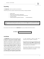
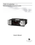
600i Evolution Series Dual-Mono Integrated Amplifier Owner’s Manual 600i Evolution Series Owner’s Manual Important Safety Instructions 1. Read these instructions. 2. Keep these instructions. 3. Heed all warnings. 4. Follow all instructions. 5. Do not use this apparatus near water. 6. Clean only with a dry cloth. 7. Do not block ventilation openings. Install in accordance with the manufacturer’s instructions. 8. Do not install near any heat sources such as radiators, heat registers, stoves or another apparatus that produces heat. 9. Do not defeat the safety purpose of the polarized or grounding type plug. A polarized plug has two blades with one wider than the other. A groundingtype plug has two blades and a third grounding prong. The wide blade or the third prong is provided for safety. If the provided plug does not fit into the outlet, consult an electrician for replacement of the obsolete outlet. 10. Protect the power cord from being walked on or pinched, particularly at plugs, convenience receptacles, and the point where they exit from the apparatus. Unplug mains cord during transportation. 11. Only use attachments and accessories specified by the manufacturer. 12. Use only with the cart, stand, tripod, bracket, or table specified by the manufacturer or sold with the apparatus. When a cart is used, use caution when moving the cart/apparatus combination to avoid injury from tip over. 13. Unplug this apparatus during lightning storms or when unused for long periods of time. 14. Refer all servicing to qualified service personnel. Servicing is required when the apparatus has been damaged in any way, such as when the power cord or plug has been damaged; liquid has been spilled or objects have fallen into the apparatus; or the apparatus has been exposed to rain or moisture, does not operate normally, or has been dropped. 15. No naked flame sources, such as candles, should be placed on the apparatus. WARNING: TO REDUCE THE RISK OF FIRE OR ELECTRIC SHOCK, DO NOT EXPOSE THIS APPLIANCE TO RAIN OR MOISTURE. 600i Evolution Series Important Safety Instructions (cont’d) The lightning flash with the arrowhead symbol, within an equilateral triangle, is intended to alert the user to the presence of uninsulated “dangerous voltage” within the product’s enclosure that may be of sufficient magnitude to constitute a risk of electric shock to persons. The exclamation point within an equilateral triangle is intended to alert the user to the presence of important operating and maintenance (servicing) instructions in the literature accompanying the appliance. Marking by the “CE” symbol (shown left) indicates compliance of this device with the EMC (Electromagnetic Compatibility) and LVD (Low Voltage Directive) standards of the European Community Please read all instructions and precautions carefully and completely before operating your MOON 600i Integrated Amplifier. 1. ALWAYS disconnect your entire system from the AC mains before connecting or disconnecting any cables, or when cleaning any component. To completely disconnect this apparatus from the AC mains, disconnect the power supply cord plug from the AC receptacle. 2. 6. NEVER wet the inside of the MOON 600i with any liquid. If a liquid substance does enter your MOON 600i, immediately disconnect it from the AC mains and take it to your MOON dealer for a complete check-up. The MOON 600i must be terminated with a three-conductor AC mains power cord which includes an earth ground connection. To prevent shock hazard, all three connections must ALWAYS be used. Connect the MOON 600i only to an AC source of the proper voltage; Both the shipping box and rear panel serial number label will indicate the correct voltage. Use of any other voltage will likely damage the unit and void the warranty 7. NEVER spill or pour liquids directly onto the MOON 600i. 8. NEVER block air flow through ventilation slots or heatsinks. 9. NEVER bypass any fuse. AC extension cords are NOT recommended for use with this product. The mains plug of the power supply cord shall remain readily accessible. 12. NEVER expose the MOON 600i to extremely high or low temperatures. 4. NEVER use flammable or combustible chemicals for cleaning audio components. 14. ALWAYS keep electrical equipment out of reach of children. 5. NEVER operate the MOON 600i with any covers removed. There are no user-serviceable parts inside. An open unit, especially if it is still connected to an AC source, presents a potentially lethal shock hazard. Refer all questions to authorized service personnel only. 15. ALWAYS unplug sensitive electronic equipment during lightning storms. 3. 10. NEVER replace any fuse with a value or type other than those specified 11. NEVER attempt to repair the MOON 600i. If a problem occurs contact your MOON dealer. 13. NEVER operate the MOON 600i in an explosive atmosphere. 16. WARNING: Do not expose batteries or battery pack to excessive heat such as sunshine, or fire or the like. Owner’s Manual Table of Contents Introduction Unpacking Installation & Placement Front Panel Controls Software Setup Rear Panel Connections SimLink™ Operating the 600i Remote Control Operation Troubleshooting Balanced Operation Specifications Quick Reference: Setup Menus 6 7 7 8 9 15 16 16 17 19 19 20 Appendix www.simaudio.com Simaudio Ltd., 1345 Newton Road Boucherville, Québec J4B 5H2 CANADA Date Code: 20150802 600i Evolution Series Introduction Thank you for selecting the MOON 600i Dual-Mono integrated amplifier as a part of your hi-fi reproduction system. This integrated amplifier has been designed to offer state-of-the-art high-end performance in an elegant package, while retaining all the sonic hallmarks on which Simaudio has made its reputation. We have spared no effort to ensure that it is among the finest two-channel integratedamplifiers available. We have been building high-performance audio equipment for over 30 years, and the know-how gained through our cumulative experience is an important reason why MOON integrated amplifiers are so musically satisfying. Your new integrated amplifier is a true Dual-mono design, whereby each channel operates completely independent of the other. The chassis, power cord and power switch are the only parts of this amplifier that both channels share. The performance of your 600i will continue to improve during the first 400 hours of listening. This is the result of a “break-in” period required for the numerous high quality electronic parts used throughout this amplifier. Before setting up your new 600i, we encourage you to please read this manual thoroughly to properly acquaint yourself with its features. We hope you enjoy listening to the MOON 600i Dual-Mono integrated amplifier as much as the pride we have taken in creating this fine audio product. We understand the power and emotion of music and build our products with the goal of faithfully capturing these elusive qualities. Our “no overall feedback” amplifier circuit design. The results are: Real-time amplification is achieved since interactions from the speaker back to the amplifier are virtually eliminated; More accurate musical reproduction with respect to tonality; Virtually non-existent transient intermodulation distortion (which is far more degrading to sonic performance than harmonic distortion); The elimination of common phase errors resulting from feedback. Custom proprietary toroidal transformer design with lower magnetic, electrical and thermal loss, yielding an improved power transfer and lower regulation factor. The result is increased current speed and better dynamics. An oversized dual-mono power supply and “Class A” power output to 5 watts for greater efficiency. SimLinkTM controller port allows for 2-way communications between other compatible MOON Evolution Series components. Each line input is fully configurable to be “home theater ready”, where the volume control of the 600i is bypassed. M-eVOL2 volume control circuit using MDAC’s (operating in a current steering R-2R configuration) which alter the audio signal’s amplitude and yield no sonic degradation of the signal regardless of the selected volume setting . M-Lock circuit for “user selectable” maximum volume setting lock-out for each line input. RS-232 port for i) full unsolicited bidirectional feedback in custom installation setups and ii) firmware updates. Gain offset for each individual line input with a ±10dB range. The information contained in this manual is subject to change without notice. The most current version of this manual is available on our official website at http://www.simaudio.com Proprietary MOON Bipolar Output transistors with unprecedented gain linearity resulting in improved bass response and even more accurate sonic reproduction. 530 individual volume steps in 1dB and 0.1dB increments. Your MOON 600i dual-mono integrated amplifier incorporates many significant design features to achieve its “world-class” level of performance. This is an abbreviated list of the more important features: 6 Ultra rigid chassis construction to minimize the effects of external vibrations. Owner’s Manual Unpacking The MOON 600i should be removed from its box with care. The following accessories should be included inside the box with your integrated amplifier: 9 9 9 9 9 AC power cable FRM-3 remote control with three ‘AAA’ batteries) SimLink™ cable with 1/8” mini plug terminations on each end This owner’s manual Warranty and product registration information (USA and Canada only) Once the 600i is unpacked, inspect it thoroughly and report any damage to your dealer immediately. We suggest that you keep all of the original packaging, storing it in a safe, dry place in case you’re required to transport this product. The customized packaging is specially designed to protect the 600i from any potential damage during transit. Please write the serial number of your new MOON 600i in the space provided below for future reference. Serial Number Installation The MOON 600i Dual-Mono integrated amplifier is both powerful and heavy. It requires reasonable ventilation to maintain an optimum and consistent operating temperature, especially since it will radiate heat when driven hard. Consequently, it should be placed in a location with empty space around it for proper heat dissipation. You should never place another component on top of this integrated amplifier. As well, the integratedamplifier should be placed on a solid level surface. You should avoid placing it near a heat source or inside a closed cabinet that is not well ventilated as this could compromise the amplifier’s performance and reliability. The 600i uses two large toroidal transformers in its power supply; even though they are well shielded, you should not place this integrated amplifier too close to source components sensitive to EMI, such as turntables, phono preamplifiers and CD Players. If the surface you have chosen isn’t perfectly level, each of the four (4) cones of your 600i are height adjustable; carefully using your fingers, you can either raise each leg by turning the cone underneath clockwise, or lower each leg by turning it counterclockwise. We strongly recommend that you leave these cones mounted to the component at all times for reasons related to both performance and aesthetics. 7 600i Evolution Series Front Panel Controls Figure 1: Front panel of MOON 600i dual-mono Integrated Amplifier The front panel will look similar to Figure 1 (above). The large display window normally indicates the current volume level and, whenever you change the input, it will briefly show the selected input label. The “Standby” button disengages the input section from the rest of the 600i’s circuitry and turns off the digital display. However, when in “Standby” mode all audio circuitry remains powered up to help maintain optimal performance. When switching back from “Standby”, both the ‘input’ and volume settings are reestablished from the previous listening session. The blue pilot LED will not be illuminated when the 600i is in “Standby” mode. The “Mute” button reduces your volume setting to zero. Pressing the “Mute” button a second time will return the output volume to its previous level. As well, adjusting the volume level while the “Mute” function is engaged will effectively defeat the muting function. The “Display” button allows you to adjust the brightness of the large digital display window. It also provides you with the option of turning off the display. There are three (3) different levels of brightness; The default is medium. Pressing the “Display” button once will increase the level to the highest setting. Pressing the button a second time will decrease the brightness to the lowest setting. Pressing the “Display” button a third time returns the display to its default setting of medium. If you want to turn the display off, press and hold the “Display” button for 2 seconds. When the display is turned off, it will still come back on for a short period of time whenever you press any of the buttons located on the front panel or the remote control, using the 8 brightness level that was previously set; the display will automatically turn off again once you are done. To turn the display back on, simply press and hold the “Display” button for 2 seconds. The “ Bal ” buttons control channel balance; Pressing the left arrow button causes a decrease in the volume level of the right channel; pressing the right arrow button causes a decrease in the volume level of the left channel. The balance adjustment operates in 1% increments. When the balance is equal for both channels, “Å 00 Æ” will appear in the front panel display. The range for the balance control varies from “Å 100” for left channel only to “100 Æ” for right channel only. The “ Input ” buttons allow you to choose which input source you wish to listen to. The MOON 600i dual-mono integrated amplifier has a total of five (5) inputs; The first input is fully-balanced and uses XLR connectors labeled B1. The next four (4) inputs are single-ended and use RCA connectors labeled S1, S2, S3 and S4. Assuming that you’re currently listening to a source component connected to input B1, the “” allows to sequentially scroll forward through the available inputs from S1 to S4. The “” button allows you to sequentially scroll backwards from S4 to B1. Holding down either the “” or ““ button will allow only a single change of the selected input. You must press the button again to select the next or previous input. Owner’s Manual The rotary “volume” control determines the gain setting, which ranges from ‘0.0dB’ (no output) to ’80.0dB’ (full output). This control does not function like a typical volume: When you rotate the dial, either clockwise to raise the volume or counter-clockwise to lower the volume, you are actually engaging a precision optical encoder which selects very high quality metalfilm resistors that the audio signal passes through. The result is a proprietary gain circuit, called M-eVOL2 that doesn’t degrade the audio signal regardless of the setting, unlike all potentiometer based circuits. Since this circuitry operates in a fully balanced differential mode, no noise is introduced to the audio signal. Furthermore, there are no actual moving parts, so this technology has a minimum life expectancy of one million rotations. The MOON 600i integrated amplifier provides a range of five-hundred and thirty (530) unique volume settings. This is achieved as follows: Within the 0.0dB to 30.0dB range, you can increase and decrease the volume in 1.0dB steps. From the 30.0dB to 80.0dB range, you can increase and decrease the volume by either 0.1dB or 1.0dB steps; By rotating the volume control slowly, the level will change by 0.1dB increments. A quicker rotation will change the volume in 1.0dB increments. The “Setup” and “OK” buttons are used for programming the numerous software functions available on this integrated amplifier. The next section, entitled “Software Setup”, explains their usage in detail. Please refer to the accompanying quick reference diagram for a snapshot of the entire Setup menu layout. When you are in Setup mode, there are five (5) front panel items used to program this integrated amplifier; The “Setup” button for navigating up and down through the various menu levels, the rotary volume control for scrolling through the available choices within each programmable item, and the “OK” button for confirming and saving your selections. What follows are step-by-step examples of how to configure an input, assign the 12 Volt trigger and reset the software back to the factory default. We will begin by walking through all 5 available options for the “B1” input: 1. To enter the Setup mode, begin by pressing the “Setup” button; “SETUP” will appear in the display window. 2. Rotate the volume control clockwise until “INPUTS” appears in the display. Press “OK”. 3. Rotate the volume control clockwise until “B1” appears in the display. Press “OK”. 4. “LABEL” will appear in the display. Press “OK”. 5. “AUX1” will appear in the display. By rotating the volume control clockwise, you will scroll through more than 25 generic choices appearing in alphabetical order (AUX … CD … TUNER, etc.), various MOON source model names (i.e. ANDROMEDA … 750D, etc) and finally a choice called “CUSTOM” which allows you to create your own text label of up to 8 characters in length (refer to the example at the end of this section for more details). If you assign the ‘’B1’ input label to “MiND” (for the MOON intelligent Network Device music streamer), you are also automatically configuring this component’s internal software which will allow it to operate with the MiND app, provided that the proper SimLink connections have been made with your other MOON components. Functions available using the MiND app are discussed in the next section. 6. When the label name you wish to assign to the B1 input appears in the display, press the “OK” button. Software Setup The MOON 600i integrated amplifier includes powerful software that allows you to configure it to meet your specific needs. For each of the five (5) inputs, you can assign a label to replace the factory assigned name (i.e. B1, S1, etc.), assign a maximum volume level of less than 80.0dB, create an offset volume level ranging from – 10.0dB to +10.0dB, bypass the volume control (to exclusively use the source component’s volume instead) and disable the input completely when it’s not in use. As well, you can assign any and all inputs to activate the 600i’s 12 Volt trigger, disable the front panel infrared sensor and change the IR code set for use with a universal remote control. Finally, there’s a facility to reset all software settings back to their factory defaults. 9 600i Evolution Series “SAVED” will briefly appear in the display followed by “LABEL”. 7. Press the “Setup” button and the label you’ve just assigned to the B1 input will appear in the display. 8. At this point you can (i) continue configuring other options for the B1 input (see the next step), (ii) configure another input such as S1 (rotate the volume control clockwise to access the S1 input), or (iii) leave the Setup mode (press the “Setup” button once and “INPUTS” appears in the display; the press it again and “EXITING” will appear in the display). 9. The next option to configure for the B1 input is the maximum volume setting. Press “OK” and “LABEL” will appear in the display. Then slowly rotate the volume control clockwise until “MAX VOL” appears in the display. Press “OK” and the factory default of “80.0dB” will appear in the display; this is the maximum volume level. 10. The maximum setting can be changed by rotating the volume control. A slow rotation makes 0.5dB adjustments and a faster rotation results in 1.0dB adjustments. Once you’ve found a desired setting, press “OK” and “SAVED” will briefly appear in the display followed by “MAX VOL”. The lowest possible setting is 40.0dB. 11. The next option to configure for the B1 input is volume offset. This allows you to compensate for the different output levels amongst your various source components you will be connecting to the 600i. Slowly rotate the volume control clockwise and “OFFSET” will appear in the display. Press “OK” and the factory default of “+6.0dB” will appear in the display. 12. You can adjust the volume offset in either 0.5dB (slow rotation) or 1.0dB (faster rotation) increments to either +10.0dB by rotating the volume control clockwise or –10.0dB rotating the volume control counter-clockwise. Once you’ve found the appropriate setting, press “OK” and “SAVED” will briefly appear in the display the “OFFSET”. 13. The fourth configurable option is the volume bypass feature for use with home-theater processors and source components that have their own volume control. When activated, the volume 10 control of the 600i is bypassed and the volume level is adjusted using the component connected to the input. Slowly rotate the volume control clockwise and “BYPASS” will appear in the display. Press “OK”. 14. The factory default of “BYPASS N” will appear in the display. Use the volume control to alternate between “BYPASS N” and “BYPASS Y” and then press “OK”. Next you will be asked to confirm your selection as “SURE ? N” will appear in the display. Rotate the volume control until “SURE ? Y” appears in the display. Press “OK” and “SAVED” will briefly appear in the display followed by “BYPASS”. When you set the volume bypass to “Y”, the volume setting you saved for the input with “OFFSET” will be maintained. 15. The fifth and final configurable option for the B1 input is to disable it if it won’t be used. Slowly rotate the volume control clockwise and “ENABLE” will appear in the display. Press “OK”. 16. The factory default is “ENABLE Y” which will appear in the display. Use the volume control to alternate between “ENABLE N” and “ENABLE Y”. Press “OK” and “SAVED” will briefly appear in the display followed by “ENABLE”. When an input has been disabled it will appear only in the Setup menu as “B1 N/A”. 17. You have now passed through all five configuration options for the B1 input. At this point, you can (i) repeat the above process for the another input by pressing the “Setup” button and then use the volume control to select the next input to configure, (ii) exit from the Setup procedure by pressing the “Setup” button three times or (iii) continue with the Setup procedure by assigning the 12 Volt trigger outputs, disabling the infrared remote sensor, changing the IR codes, or resetting the 600i back to factory default status (see the following examples). The MOON 600i is equipped with software that allows the MiND app to control various features of this preamplifier. With the MiND app you will be able to adjust the volume level, mute the output, place the preamplifier into ‘Standby’ mode and then place it back into operational mode. As well, when you begin playing Owner’s Manual a music track from the MiND app, the 600i will automatically switch to the input configured for the MiND. With the MiND app, you are essentially controlling your entire MOON system using a hand-held Apple (iPad, iPhone, iPod Touch,) device. 2. When “CUSTOM” appears in the display press the “OK” button. The display will show “……………………………” . 3. Rotate the volume control clockwise to scroll through the 26 letters of the English alphabet, first in uppercase and then lowercase, followed by the numbers 0 through 9, and finally several miscellaneous symbols including the space character. When you see the letter, number or symbol you wish to use, press “OK” to select it and then repeat this step for the next character. You must assign all 8 characters when creating a custom input label; If your label requires only 5 characters, you will need to input a blank space for the remaining 3 characters. Note: If you decide to create a custom input label for MiND, it must be spelled exactly as it appears here – the software is case sensitive. You don’t need to LABEL an input with “MiND” to achieve these aforementioned functions , but you must configure one input for MiND functionality. An example for this scenario would be the 180 MiND streaming device feeding a digital signal to a MOON 650D DAC /Transport, which then outputs its analog signal to the MOON 600i. 4. Only one of the five inputs may be configured for the MiND. “B1” is the default input. If, in the previous section, you already assigned the “MiND” label to one of this preamplifier’s inputs, then there’s nothing required to do here – The corresponding input has been automatically configured for MiND and cannot be changed until you change the input ‘LABEL” assigments. However, if you haven’t assigned the “MiND” label to one of the 600i’s inputs, the following example shows how to configure an input for MiND functionality: 1. You may either continue where we left off in the previous example by pressing “Setup” twice to return to the main menu and the turn the volume control until “MiND” appears in the display OR enter into the “Setup” mode from the beginning by pressing the “Setup” button and rotating the volume control until “MiND” appears in the display. 2. Press “OK” and “MiND:B1” will appear in the display. 3. Rotate the volume control clockwise until the input you want to configure appears in the display. 4. Press “OK” and “SAVED” will appear brielfy in the display followed by “MiND”. 5. Press the “Setup” button and “EXITING” will appear in the display. 5. Once you’ve filled the last position, press”OK” and “SAVED” will briefly appear in the display followed by “INPUTS”. 6. Press the “SETUP” button to exit from the Setup menu. A pair of single-ended RCA connectors labeled “LINE OUT” can be found on the MOON 600i’s rear panel. The output level can be configured as either fixed level (for use with a recording device) or variable level (for use with a sub-woofer or when using the MOON 600i only as a preamplifier). This is done as follows: 1. You may either continue where we left off in the previous example by pressing “Setup” twice to return to the main menu and the turn the volume control until “LINE OUT” appears in the display OR enter into the “Setup” mode from the beginning by pressing the “Setup” button and rotating the volume control until “LINE OUT” appears in the display. 2. Press “OK” and “VARIABLE” will appear in the display. 3. To change the output to fixed, rotate the volume control to alternate from “VARIABLE” to “FIXED” Assigning a custom label to an input: 1. Using the example from the previous page for configuring an input, repeat steps 1 through 5. 11 600i Evolution Series 4. Press “OK” and “SAVED” will appear briefly in the display followed by “LINE OUT”. The MOON 600i is equipped with a 12 Volt trigger output. When an input is assigned to the 12 Volt trigger, the device connected to the trigger will automatically start-up whenever you switch to that input. The default setting for all five inputs is on. When you set the IR input to “Y”, all inputs previously set to “Y” for that trigger will automatically be set to “N”. Then the trigger will be controlled exclusively by an external IR signal. The following example shows how to configure it: 1. You may either continue where we left off in the previous example by pressing “Setup” twice to return to the main menu and the turn the volume control until “TRIGGER” appears in the display OR enter into the “Setup” mode from the beginning by pressing the “Setup” button and rotating the volume control until “TRIGGER” appears in the display. 2. Press “OK” and “B1 : Y” will appear in the display. 3. To disable the 12 Volt trigger, press “OK” and “B1 ? Y” appears in the display; rotate the volume control to alternate from “Y” to “N” . 4. Press “OK” and “SAVED” will appear briefly in the display followed by “B1 : N”. 5. To configure another input, rotate the volume control until that input appears in the display, then press “OK”. 6. Repeat steps 3 and 4. 7. When you have finished with all of the inputs for the “TRIGGER” press the “Setup” button and “TRIGGER” will appear in the display. From this point you can (i) exit from the Setup procedure by pressing the “Setup” button again and “EXITING” will appear in the display or (ii) continue with the Setup procedure by disabling the infrared remote sensor, changing the IR codes, resetting the 600i back to factory default status (see the following examples) (iii) or configuring more inputs (example on previous page). 12 If you want to control the MOON 600i using a wired aftermarket infrared remote control receiver with a universal remote control, you can disable the IR sensor located on the front panel as follows: 1. You may either continue where we left off in the previous example by pressing “Setup” twice to return to the main menu and the turn the volume control until “INFRARED” appears in the display OR enter into the “Setup” mode from the beginning by pressing the “Setup” button and rotating the volume control until “INFRARED” appears in the display. 2. Press “OK” and “NORMAL” will appear in the display. 3. To disable the MOON 600i’s front panel IR sensor, rotate the volume control to alternate from “NORMAL” to “DISABLED” . 4. Press “OK” and “SAVED” will appear briefly in the display followed by “INFRARED” 5. Press the “Setup” button to exit from the Setup menu. The MOON 600i is equipped with a rear mounted IR input for use with aftermarket wired infrared remote control receivers. In the event that you want control the MOON 600i with a universal remote control and NOT the one included (FRM-3), you can change the RC-5 remote control system codes. This procedure is recommended when you have a large custom install setup that uses multiple integrated amplifiers and/or preamplifiers that operate on the RC-5 standard and you need to make each component unique w.r.t. remote control operation – up to 4 components. Before making the following change, you should have a basic understanding how to program a universal remote control. The following example shows how to change the IR codes that the MOON 600i will recognize: 1. You may either continue where we left off in the previous example by pressing “Setup” twice to return to the main menu and the turn the volume control until “IR CODE” appears in the display OR enter into the “Setup” mode from the beginning by pressing the “Setup” button and rotating the Owner’s Manual volume control until “IR CODE” appears in the display. 2. Press “OK” and “DEFAULT” will appear in the display. 3. To change the RC-5 system codes, rotate the volume control to scroll through the available sets of RC-5 compatible codes: “SYS11”, “SYS14”, “SYS15”, and “SYS19”. 4. 5. Once you’ve decided on one, Press “OK” and “SAVED” will appear briefly in the display followed by “IR CODE”. From this point you can (i) exit from the Setup procedure by pressing the “Setup” button again and “EXITING” will appear in the display or (iii) continue with the Setup procedure by disabling the infrared remote sensor, changing the IR codes, resetting the 600i back to factory default status (see the following example), configure the 12 Volt Trigger Output or configure more inputs (examples on previous pages). 1. You may either continue were we left off in the previous example by turning the volume control until “RESET” appears in the display OR enter into the “Setup” mode from the beginning by pressing the “Setup” button and then rotating the volume control until “RESET” appears in the display. 2. Press “OK” and “RESET N” will appear in the display. 3. Rotate the volume control until “RESET Y” appears in the display. 4. Press “OK” and “SURE ? N” will appear in the display. 5. Rotate the volume control until “SURE ? Y” appears in the display. 6. Press “OK” and “SAVED” will briefly appear in the display followed by “RESET”. 7. Press the “Setup” button again and “EXITING” will appear in the display. Reset the MOON 600i software settings back to their factory defaults: 13 600i Evolution Series Rear Panel Connections Figure 2: Rear panel of MOON 600i Integrated Amplifier The rear panel of the MOON 600i dual-mono integrated amplifier will look similar to Figure 2 (above). There are two rows of connectors; the upper row contains one pair of heavy duty gold-plated speaker binding posts for each channel to connect to your loudspeakers. In between these binding posts are four (4) pairs of single-ended RCA inputs labeled S1, S2, S3, and S4. This layout is the result of 600i’s dual-mono design, the left channel inputs/outputs are grouped together on one side and the right channel inputs/outputs are grouped together on the opposite side. On the lower row, beginning on the left side, you will find a full-function bi-directional RS-232 port control and status for custom integration or automation using a DB9 connector. Immediately to the right of the RS-232 port are two (2) “SimLink” connectors labeled “in” and “out” on 1/8” mini jacks. Please refer to the next section entitled SimLink for more details. As well, there’s a 1/8” mini-jack input for use with aftermarket infrared remote control receivers. Further to the right, there’s a 12V trigger output on a 1/8” mini-jack. The MOON 600i is equipped with a “Line Out”, that can be configured as either a fixed or variable output (refer to page 12 in the section entitled “Software Setup” for details). Beside each of the “Line Out” connectors are balanced XLR inputs labeled B1, with each channel’s input connector located on its respective side, just like the single-ended inputs. Finally, on the right is the “AC Power” section with the “AC Fuse” socket cover, a main power switch (“0”=off, “1”=on) and the IEC receptacle for the included AC power cord. As well, don’t hesitate to use high quality interconnect cables. Poor quality interconnect cables can degrade the overall sonic performance of your system. All rear panel connectors have been chosen because they provide the best possible connections for your unit. A poor contact will degrade the signal substantially, and plugs and sockets should all look 14 clean and free of dirt and corrosion. The easiest way to clean them is to remove the cables from their sockets and push them back in again. This procedure requires that your integrated amplifier and the rest of your components be completely turned off. SimLink™ The SimLink™ provides communication features between various MOON components. For example, if you were to connect the 750D CD Player to the 600i Integrated Amplifier via the SimLink™, pressing the X (play) button on the 750D would cause the integrated amplifier to automatically switch to it’s designated input for the CD Player. You must assign the input with the name “750D” for this feature to work. If you were to adjust the brightness level of the large digital display window using the “Display” button on the 600i, the brightness level of the 750D’s display will automatically adjust to the same brightness level as that of the 600i. Conversely, since the SimLink™ is a true bi-directional connection, adjusting the 750D’s brightness level will automatically adjust the brightness level of the 600i. Owner’s Manual A third feature of SimLink™ involves the “Standby” function. By pressing down and holding the “Standby” button for 2 seconds on the 600i, all other MOON components connected via the SimLink will go into “Standby” mode along with the 600i. The same logic applies when switching from “Standby” to active mode. The connection rules for the SimLink™ are very basic. You must always connect the supplied cable between one component’s “SimLink™ Out” jack and another component’s “SimLink™ In” jack. If you inadvertently connect the cable between either two “SimLink™ In” or two “SimLink™ Out” jacks, the SimLink™ communication feature will not function. Also, there is no master component in a SimLink™ chain; no one particular component operates as the main communications controller. If you are using your MOON 600i with an older MOON product such as a SuperNova, you will need to update the software of the older product to allow for complete SimLink™ functionality. Contact your retailer for further details. Operating the 600i We recommend that you leave your MOON 700i dualmono integrated amplifier powered up at all times to maintain optimal performance. When you plan to be away from your home for a few days, powering off the preamplifier may not be a bad idea. Once fully “brokenin”, please keep in mind that your 700i will require several hours of playing time before it reaches its peak performance after you’ve powered it up again. Turning on your MOON 700i for the first time Prior to turning the integrated amplifier on for the first time, make sure that every cable is properly connected to avoid any problems. Flick the main rocker switch, located on the rear panel, labeled “POWER” to the ‘1’ (on) position to place your 700i in to standby mode. Next, briefly press the push button labeled “Standby” located on the front panel. You will hear a very faint click sound confirming that everything is in order. The blue LED on the front panel will illuminate, indicating that the 700i is now powered up and ready for use. On and Off Sequence To avoid having any annoying noises (ie. “thumps” and “pops”) emanate from your speakers when powering your 700i on or off, you should always power up your 700i integrated amplifier after powering up your source component(s). As well, always power down your 700i before powering down your source component(s). 15 600i Evolution Series Remote Control Operation The MOON 600i Dual-Mono Integrated Amplifier uses the ‘FRM-3’ full function, all aluminum backlit remote control (figure 3). It operates on the Philips RC-5 communication protocol and is can be used with other MOON components such as CD Players, DAC’s, Integrated Amplifiers, as well as other Preamplifiers. The ‘FRM-3’ remote uses three AAA batteries (included). To install them, use a Phillips head screwdriver #1 to remove the three screws located on the rear plate; insert the batteries in the correct direction and then screw the rear plate back into place. To operate the 600i with this remote control, you must first press the AMP button located on the second row from the top. The power button switches the 600i between ‘Standby’ and ‘On’ mode. The Balance W and Balance X buttons control channel balance; Pressing the left arrow button causes a decrease in the volume level of the right channel; pressing the right arrow button causes a decrease in the volume level of the left channel. The balance adjustment operates in 1% increments. When the balance is equal for both channels, “Å 00 Æ” will briefly appear in the front panel display. The range for the balance control varies from “Å 100” for left channel only to “100 Æ” for right channel only. The Input S and Input T buttons allow you to sequentially scroll through each of the preamplifier’s inputs, performing the identical function as the ‘Input’ buttons located on the 600i’s front panel The Mute button, located between the input and volume buttons, reduces your volume setting to zero, performing the identical function as the ‘Mute’ button located on the 600i’s front panel. The VolS and VolT buttons increase and decrease the volume level. From 30 to 80dB, holding either button down results in 1.0dB volume changes; repeatedly pressing either button very briefly results in 0.1dB volume changes. The Disp button allows you to adjust the brightness of the digital display window. It also provides you with the option of turning off the display, performing the identical function as the ‘Display’ button located on the 600i’s front panel. Figure 3: FRM-3 Remote Control 16 Owner’s Manual Backlight Function Your FRM-3 features a backlight capability that allows you to effortlessly operate this remote control in a darkened environment. Since battery lifespan is substantially reduced when the backlighting feature is activated, the FRM-3 includes 3 different operational modes to help preserve battery life: Default Mode (#1): The backlight is triggered on by either moving the remote control (via an internal motion detector) or by pressing any button on the remote’s keypad; The backlight will remain illuminated for a full five (5) seconds after the last event (motion or pressed button). To activate the “Default Mode”, press and hold the “CD” button for three (3) seconds. The backlight will illuminate once, very briefly for confirmation. Button Mode (#2): The backlight is triggered ONLY by pressing any button on the remote’s keypad - the internal motion detector is deactivated; The backlight will remain illuminated for a full five (5) seconds after the last button is pressed. To activate the “Button Mode”, press and hold the “AMP” button for three (3) seconds. The backlight will illuminate twice, very briefly for confirmation. Off Mode (#3): The backlight feature is completely disabled. To activate the “Off Mode”, press and hold the “DAC” button for three (3) seconds. The backlight will illuminate three times, very briefly for confirmation. Remote operation with multiple MOON components Figure 4: Remote Operation with SimLink™ In figure 4 we have a 180 MiND Music Streamer connected to a 650D DAC via their respective SimLink™ ports (using a 1/8” mini-jack cable), and the 650D connected to a 600i Integrated Amplifier also via their respective SimLink™ ports. When you launch the MiND App on your Apple smart device (full list on the MiND page of our website) and select this system’s ZONE, the 180 MiND will turn on, as will the 650D and 600i; The 600i will automatically switch to its “MiND” assigned input. To shut down the system, press “Off” for this ZONE in the MiND app. 17 600i Evolution Series Figure 5: Remote Operation with 12V Trigger In figure 5 we have a 600i Integrated Amplifier (used either as ONLY a preamplifier or in a bi-amping configuration) connected to a 860AP Power Amplifier via their respective 12V triggers (using a 1/8” mini-jack cable). When you turn on the 600i via remote control (or its Standby button), the 860A will turn on automatically. The same rule applies when you put the 600i into Standby mode. Troubleshooting Balanced Operation Your MOON 600i is a “smart” integrated amplifier equipped with a self-diagnostic system that will automatically shut itself down when it (i) detects DC (direct current) from any input or (ii) reaches a dangerously high operating temperature. When DC is present, the front panel display will show “DC LEVEL”; when overheating “OVERTEMP” will appear in the display. If your 600i powers itself off or will not power up, there may very well be DC present in one (or more) of the inputs coming from one (or more) of your source components. You must determine if there is any DC present. The best way to accomplish this is by first powering down the 600i via the main power rocker switch, then physically removing all inputs to the 600i leaving only the speakers connected. Attempt to power up your 600i again: A successful power up will indicate the presence of DC coming from one of your signal sources (ie. CD Player). When using an unbalanced interconnect, the audio signal runs through both the center wire and the shield/ground wire. Any noise picked up by this interconnect (ie. nearby magnetic fields such as an AC power cord) will be reproduced by the integrated amplifier, then heard through the loudspeakers. Conversely, a balanced interconnect has three separate conductors; one for the ground and two for the actual signal. These two signals are identical except that one is 180 degrees out of phase with the other. For example, when one conductor is carrying a signal of +10 Volts, the other will be carrying a signal of –10 Volts. When these two inverted signals on a balanced line are output from the MOON 600i, any noise picked up by the interconnect will be eliminated since a differential circuit amplifies only the difference between these two signals: Noise on a balanced interconnect will be equal on both conductors and therefore cancel out. 18 Owner’s Manual Specifications Configuration Fully balanced, dual-mono Power Supply Transformers 2 x 400VA Power Supply Capacitance 80,000μF Single-ended inputs (RCA) 4 pairs Input Impedance 23,700Ω Input Sensitivity 490mV – 6,0V RMS Preamplifier line-level output (RCA) 1 pair @ 50Ω Output Device Type – Amplifier Proprietary MOON Bipolars - 4 per channel Output Power @ 8Ω 125 Watts per channel Output Power @ 4Ω 250 Watts per channel Volume Steps 0.5dB from 0-30 and 0.1dB from 30-80 Gain Control M-eVOL2 Gain 37dB Signal-to-noise Ratio (Preamplifier/Amplifier) 120dB (20-20kHz) / 105dB @ 125W Frequency Response 10Hz – 100kHz +0/-0.1dB Crosstalk @ 1kHz 100dB Intermodulation Distortion 0.02% THD (20Hz - 20kHz @ 1 watt) 0.015% THD (20Hz - 20kHz @ 125 watts) 0.04% Remote Control All Aluminum Full-Function (FRM-3) Display Type 8 character dot matrix LED Power Consumption @ idle 45 Watts AC Power Requirements 120V / 60Hz or 240V / 50Hz Shipping Weight 48 lb. / 21 Kg. Dimensions (W x H x D, inches / cm.) 18.75 x 4.0 x 18.1 / 47.6 x 10.0 x 46.0 Balanced Input Pin Assignment: Pin 1 Pin 2 Pin 3 Ground Positive Negative 19 600i Evolution Series NOTE: If you require the RS-232 codes for your 600i, please visit the "Contact Us" page and complete the "Information request" form on our website at www.simaudio.com. Fuse Replacement: For the 120V version use a 6A fast blow (3AG size). For the 230V version use a 3A fast blow (3AG size) 20 B1 S1 S2 S3 S4 INPUTS SETUP MAX 80.0dB* MAX 79.9dB . . MAX 40.0dB AUX CD DVD PHONO SACD SAT SURROUND TAPE TUNER TV VIDEO ANDRMEDA MiND SUP.NOVA 260D 280D 380D 430HA 650D 750D 780D CUSTOM: A… Z a… z 0… 9 ():.,< >-#* MAX VOL LABEL +10.0dB +9.9dB . . +6.0dB * +5.9dB . . 0.0dB . . -10.0dB OFFSET B1 * S1 S2 S3 S4 SURE ? N SURE ? Y BYPASS N* BYPASS Y BYPASS MiND: MiND: MiND: MiND: MiND: MiND B1: Y S1: Y S2: Y S3: Y S4: Y IR: N TRIGGER NORMAL * DISABLED INFRARED * Denotes factory default setting ENABLE Y* ENABLE N ENABLE VARIABLE * FIXED LINE OUT Quick Reference: MOON 600i Setup Menus DEFAULT * SYS 11 SYS 14 SYS 15 SYS 19 IR CODE V. 03 FIRMWARE SURE ? N SURE ? Y RESET N RESET Y RESET