1
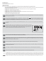
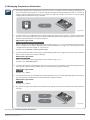
GSM ALARM AND MANAGEMENT SYSTEM user manual ESIM364 User Manual v1.1 Valid for ESIM364 v02.01.18 and up Safety instructions Please read and follow these safety guidelines in order to maintain safety of operators and people around: • GSM alarm & management system ESIM364 (also referenced as alarm system, system or device) has radio transceiver operat ing in GSM 850/900/1800/1900 bands. • DO NOT use the system where it can be interfere with other devices and cause any potential danger. • DO NOT use the system with medical devices. • DO NOT use the system in hazardous environment. • DO NOT expose the system to high humidity, chemical environment or mechanical impacts. • DO NOT attempt to personally repair the system. • System label is on the bottom side of the device. GSM alarm system ESIM364 is a device mounted in limited access areas. Any system repairs must be done only by quali fied, safety aware personnel. The system must be powered by main 16-24V 50 Hz ~1.5A max or 18-24V 1,5A max DC power supply which must be approved by LST EN 60950-1 standard and be easily accessible nearby the device. When connecting the power supply to the system, switching the pole terminals places does not have any affect. Any additional devices linked to the system ESIM364 (computer, sensors, relays etc.) must be approved by LST EN 60950-1 standard. Main power supply can be connected to AC mains only inside installation room with automatic 2-pole circuit breaker capable of disconnecting circuit in the event of short circuit or over-current condition. Open circuit breaker must have a gap between con nections of more than 3mm and the disconnection current 5A. Phase Null PE AC/DC AC 230V 50 Hz/DC 24V ESIM364 USB cable Mains power and backup battery must be disconnected before any installation or tuning work starts. The system installa tion or maintenance must not be done during stormy conditions. Backup battery must be connected via the connection which in the case of breaking would result in disconnection of one of battery pole terminals. Special care must be taken when connecting positive and negative battery terminals. Switching the pole terminals places is NOT allowed. In order to avoid fire or explosion hazards the system must be used only with approved backup battery. The device is fully turned off by disconnecting 2-pole switch off device of the main power supply and disconnecting backup battery connector. Fuse F1 type – Slow Blown 3A. Replacement fuses have to be exactly the same as indicated by the manufacturer. If you use I security class computer for setting the parameters it must be connected to earth. The WEEE (Waste Electrical and Electronic Equipment) marking on this product (see left) or its documentation indicates that the product must not be disposed of together with household waste. To prevent possible harm to human health and/or the environ ment, the product must be disposed on in an approved and environmentally safe recycling process. For further information on how to dispose of this product correctly, contact the system supplier, or the local authority responsible for waste disposal in your area. Limited Liability The buyer must agree that the system will reduce the risk of fire, theft, burglary or other dangers but does not guarantee against such events. “ELDES UAB” will not take any responsibility re garding personal or property or revenue loss while using the system. “ELDES UAB” liability ac cording to local laws does not exceed value of the purchased system. “ELDES UAB” is not affiliated with any of the cellular providers therefore is not responsible for the quality of cellular service. Manufacturer Warranty The system carries a 24-month warranty by the manufacturer “ELDES UAB”. Warranty period starts from the day the system has been purchased by the end user. The warranty is valid only if the system has been used as intended, following all guidelines listed in the manual and within speci fied operating conditions. Receipt must be kept as a proof of purchase date. The warranty is voided if the system has been exposed to mechanical impact, chemicals, high humidity, fluids, corrosive and hazardous environ ments or other force majeure factors. Technical Support If you require more detailed information on your system or in case of system failure occurrence, please, contact your alarm system installer. About User Manual This document describes basic configuration and usage of alarm system ESIM364. It is very impor tant to read the user manual before starting to use the system. Package Content 1. ESIM364................................................. qty. 1 2. Microphone.......................................... qty. 1 3. SMA antenna....................................... qty. 1 4. Backup battery connection wire.qty. 1 Contents 1. General Information...................................................................... 4 1.1 1.2 1.3 1.4 Short Description of Main Definitions................................................4 EKB2 Keypad Overview............................................................................5 EKB3/EKB3W Keypad Overview............................................................7 Partitions.......................................................................................................7 2. Technical Specifications................................................................ 8 2.1 2.2 2.3 Electrical & Mechanical Characteristics..............................................8 Main Unit, LED & Connector Functionality.......................................9 Wiring Diagrams...................................................................................... 10 2.3.1 General Wiring.......................................................................... 10 2.3.2 Zone Connection Types......................................................... 10 3. Basic Configuration & Use...........................................................11 3.1 Setting Up Date & Time......................................................................... 11 3.2. Arming, Disarming the System & Turning Off the Alarm.......... 12 3.2.1 Arm, Disarm & Turn off the Alarm by Phone Call.......... 12 3.2.2 Arm by SMS text message.................................................... 13 3.2.3 Disarm & Turn off the Alarm by SMS text message..... 13 3.2.4 Arm by EKB2 Keypad.............................................................. 14 3.2.5 Disarm & Turn off the Alarm by EKB2 Keypad............... 14 3.2.6 Arm by EKB3/EKB3W Keypad.............................................. 15 3.2.7 Disarm & Turn off the Alarm by EKB3/EKBW Keypad.. 15 3.2.8 Arm by iButton® Key............................................................... 16 3.2.9 Disarm & Turn off the Alarm by iButton® Key................ 16 3.2.10 Arm by EWK1 – Wireless Key-fob........................................ 17 3.2.11 Disarm & Turn off the Alarm by EWK1 – Wireless Key-fob.................................... 18 3.3 Activating STAY Mode........................................................................... 19 3.3.1 Arm by EKB2 Keypad in STAY Mode Manually............... 19 3.4 Alarm Indications & Viewing Violated Zones / Tampers............ 21 3.5 Bypassing & Activating Zones............................................................ 22 3.6 Viewing System Information............................................................... 23 3.7 Managing Periodical System Information...................................... 23 3.8 Viewing Zone & PGM Output Information..................................... 24 3.9 Managing Temperature Information............................................... 25 3.10 Indication of System Faults.................................................................. 26 3.11 Controlling Electrical Appliances...................................................... 28 3.12 Turning ON/OFF the Electrical Appliances for a Determined Time Period..................................... 29 4. If the Alarm System is Connected to Monitoring Station.........30 5. User manual......................................... qty. 1 6. Resistor 5,6kΩ....................................qty. 12 7. Resistor 3,3kΩ...................................... qty. 6 NOTE: For complete system configuration and control, please refer to ESIM364 installation manual located at www.eldes.lt/en/download Copyright © “ELDES UAB”, 2012. All rights reserved It is not allowed to copy and distribute information in this document or pass to a third party without advanced written authorization by “ELDES UAB”. “ELDES UAB” reserves the right to update or modify this document and/or related products without a warning. Hereby, “ELDES UAB” declares that this GSM alarm and management system ESIM364 is in compliance with the essential requirements and other relevant provisions of Directive 1999/5/EC. The declaration of conformity may be consulted at www.eldes.lt 1. General Information ESIM364 is an alarm system for private houses, cottages, village houses, garages, warehouses and other buildings, also capable of turning on/off the electrical appliances by SMS text message and alarm system keypad. This alarm system provides a simple thus effective way of use. The system may consist of: • ESIM364 alarm system device. • Up to 4 EKB2/EKB3 wired keypads. • Up to 4 EKB3W wireless keypads. • Wired and/or wireless detection devices: movement sensors, magnetic door contacts, smoke sensors etc. • Other devices: indoor/outdoor sirens, zone/PGM output expansion modules, heating, lighting, gates etc. For more details on ESIM364 system, please, consult with your alarm system installer. 1.1 Short Description of Main Definitions The following table provides the explanation of main definitions which are met in this user manual. Definition Description System; alarm system ESIM364 device SMS Short Message Service text Keypad Device with a set keys allowing to configure & control the system, view violated zones & system troubles EKB2 Model of wired LCD keypad EKB3 Model of wired LED keypad EKB3W Model of wireless LED keypad User phone number; User 1... 10 Phone number of the user allowed to control and receive SMS text messages from the system System phone number Phone number of the SIM card inserted in ESIM364 device User password 4-digit combination intended for system arming/disarming using a keypad iButton® key Small metal tab containing a unique ID code intended for system arming/disarming Zone Alarm system input for wired and wireless sensor connection PGM output Alarm system output for connection of electrical appliances (heating, lighting, gates etc.) Partition Section dividing one alarm system into two independent parts software-wise 4 1.2 EKB2 Keypad Overview EKB2 is an LCD keypad intended for using with ESIM364 alarm system. Temperature Keys Functionality One menu level back / cancel GSM Signal Strength Digital Clock 20,20C Menu navigation – up System Status Message Menu navigation – down Confirm (enter) value ... Value typing Keypad partition switch / minus symbol for entering negative temp. value STAY BYP TBL 00:45 ready GARAGE Home Screen View Bypass Mode Indication System Trouble Indication Stay Mode Indication Custom Keypad Partition Title Additional menu / minus symbol for entering negative temp. value Fig. No. 1 Main Messages & Icons Icon / Message Description Delay zone violated when system is disarmed. Exit delay countdown initiated. System is armed and menu is locked. System is disarmed and menu is unlocked Icon / Message 24H zone violated. FIRE ALARM Fire zone violated. TAMPER ALARM READY NOT READY ARMED + CONFIGURATION MODE BURGLARY ALARM Configuration Mode activated. Delay, Instant or Follow zone violated when system is armed. MANUAL ELDES ESIM364 v1.1 Description 24 ALARM Tamper violated System is ready to be armed. System is not ready to be armed – one or more zones / tampers violated. System is armed (optional feature). STAY Stay mode activated BYP One or more zones bypassed TBL One or more system troubles are present 5 EKB2 LCD screen is intended for displaying alarm system status messages and alerts. Message READY is displayed on the screen that no zones are violated or no troubles are present and the system is prepared for arming. Message NOT READY (and TBL) shows up in case of zone violation or if system troubles are present. The alarm system cannot be armed until the troubles are removed or violated zone (-s) is restored, bypassed or set up to operate under Force mode. The following troubles allow system arming when present: • main power supply is lost. • low battery. • battery dead or missing. • battery failed. • siren failed. • GSM jammer detected. • date/time not set. • GSM connection failed. • GSM antenna failed. Audio Indication The built-in buzzer uses two types of sound signals – three short beeps and one long beep. Three short beeps stand for successfully carried out configuration command, one long beep – for invalid configuration command. In addition, the buzzer continuously emits short beeps in case of alarm and during exit/entry delay. Visual Indication EKB2 can be used even in dark premises as the LCD screen and keys are illuminated continuously. In case of alarm the keypad illumina tion level is boosted and stays in this state until the system is disarmed. The illumination level lowers down in 3 minutes after the last key-touch while the system is disarmed. 6 1.3 EKB3/EKB3W Keypad Overview EKB3/EKB3W is a LED keypad intended for using with ESIM364 alarm system. LED Functionality ARMED Alarm system is armed /Configuration mode READY System is prepared for arming SYSTEM System troubles / valid command is being entered BYPS Zone bypass mode 1-12 Violated zone A B ARMED READY SYSTEM 1 BYPS 7 8 2 9 3 4 5 6 10 11 12 1 2 3 STAY 4 5 6 BYPS 7 8 9 INST * 0 # CODE Fig. No. 2 Keys Functionality [BYPS] Zone bypass mode [CODE] Additional options - system trouble list / violated high zone indication / violated tamper indication [*] Configuration Mode (when typed as a 1st character) / cancel command (when typed as a 2nd character) / keypad partition switch (if enabled) [#] Confirm (enter) command [0] ... [9] Command typing [STAY] Manual Stay mode activation [INST] (currently inactive) The green indicator READY indicates that no zones are violated or no troubles are present and the system is prepared for arming. Yellow indicator SYSTEM lights up or flashes in case of zone violation or if system troubles are present. The alarm system cannot be armed until the troubles are removed or violated zone (-s) is restored, bypassed or set up to operate under Force mode. The following troubles allow system arming when present: • main power supply is lost. • low battery. • battery dead or missing. • battery failed. • siren failed. • GSM jammer detected. • date/time not set. • GSM connection failed. • GSM antenna failed. Audio Indication The built-in buzzer uses two types of sound signals – three short beeps and one long beep. Three short beeps stand for successfully carried out configuration command, one long beep – for invalid configuration command. In addition, the buzzer continuously emits short beeps in case of alarm and during exit/entry delay. Visual Indication EKB3 keys have a LED back-light, therefore it is possible to use this keypad even in dark premises. In case of alarm the keypad backlight turns on and lasts until the system is disarmed. The back-light lasts for 3 minutes after the last key-stroke while the system is disarmed. Due to battery power saving reasons the EKB3W keypad back-light and LED light last for 10 seconds after the last key-stroke. However, this duration is configurable. 1.4 Partitions Your alarm system may be divided into up to 4 partitions: Partition 1 - Partition 4 . Each system partition operates independently from each other, therefore dividing the system into partitions allows to use 1 alarm system unit to secure up to 4 different areas, for example: office and warehouse, house and garage etc. By default configuration, the system is NOT divided into partitions and all user phone numbers, user passwords, keypads, iButton® keys, zones are assigned to Partition 1. MANUAL ELDES ESIM364 v1.1 7 2. Technical Specifications 2.1 Electrical & Mechanical Characteristics Electrical & Mechanical Characteristics Main Power Supply Current in Standby without External Sensors and Keyboard Recommended Backup Battery Voltage, Capacity Recommended Backup Battery Type Maximum Battery Charge Current GSM Modem Frequency Cable Type for GSM Antenna Connection Number of Zones on Board Nominal Zone Resistance Number of PGM Outputs on Board ESIM364 PGM Output Circuit 16-24V 50 Hz ~1.5A max / 18-24V Up to 80mA 12V; 1,3-7Ah Lead-Acid 900mA 850/900/1800/1900MHz Shielded 6 (ATZ mode: 12) 5,6kΩ (ATZ Mode: 5,6kΩ and 3,3kΩ) 4 Maximum Commuting PGM Output Values BELL: Siren Output when Activated BELL: Maximum Siren Output Current BELL: Maximum Cable Length for Siren Connection BELL: Cable Type for Siren Connection AUX: Auxiliary Equipment Power Supply Voltage AUX: Maximum Accumulative Current of Auxiliary Equipment AUX: Maximum Cable Length for Auxiliary Equipment Connection AUX: Cable Type for Auxiliary Equipment Connection BUZ: Maximum Current of Mini Buzzer BUZ: Power Supply Voltage of Mini Buzzer BUZ: Cable Type for Mini Buzzer Connection Dimensions Operating Temperature Range Supported Temperature Sensor Model Maximum Supported Number of Temperature Sensors DATA: Maximum Cable Length for 1-Wire® Communication DATA: Cable Type for 1-Wire® Communication Supported iButton® Key Model Maximum Supported Number of Keyboards Y/G: Maximum Cable Length for RS485 Communication Y/G: Cable Type for RS485 Communication MIC: Maximum Cable Length for Microphone Connection MIC: Cable Type for Microphone Connection Voltage – 30V; Current – 100mA; Connected to COM 1A up to 30 meters Unshielded 13,8V DC 1,1A up to 100 meters Unshielded 150mA 5V DC Unshielded 140x100x18mm -20...+550C Maxim®/Dallas® DS18S20, DS18B20 8 up to 30 meters Unshielded Maxim®/Dallas® DS1990A 4 x EKB2 / EKB3 up to 100 meters Unshielded Up to 2 meters Unshielded Wireless Transmitter-Receiver Frequency 868 Mhz Wireless Communication Range Maximum Supported Number of Wireless Devices Event Log Size Maximum Supported Number of Zones Maximum Supported Number of PGM Outputs Cable Type for Zone and PGM Output Connection Communications Supported Protocols Up to 30m in premises; up to 150m in open areas 32 500 events 76 76 Unshielded SMS, Voice calls, GPRS network, RS485, CSD, PSTN Ademco Contact ID®, 4+2, EGR100, Kronos, Cortex® 8 1R OUT 1,5A max Open Collector Output. Output is pulled to COM when turned ON. 2.2 Main Unit, LED & Connector Functionality Main Unit Functionality GSM network 850/900/1800/1900MHz modem SIM card slot / holder SIM CARD2 SIM card slot / holder DEF Pins for restoring default settings USB Mini USB port FUSE F1 3A fuse W-LESS ANT Wireless antenna SMA type connector GSM ANT GSM antenna SMA type connector MODULES* Slots for EA1, EA2 or EPGM8 module SIM CARD1 GSM ANT SIM CARD2 GSM MODEM DEF 3A PRG FUSE F1 SIM CARD1 W-LESS ANT C4 C3 GSM MODEM STAT C4 C3 C2 C1 NETW USB MODULES TIP RING AKU+ AKU- AC/DC AC/DC AUX+ AUXBELL+ BELLCOM G Y C2 C1 BUZ+ BUZMIC+ MIC+5V DATA COM Z6 COM Z5 Z4 COM Z3 Z2 COM Z1 LED Functionality NETW GSM network signal strength C1 PGM output C1 status - on/off C2 PGM output C2 status - on/off C3 PGM output C3 status - on/off C4 PGM output C4 status - on/off STAT Micro-controller status Fig. No.1 Connector Functionality TIP* PSTN (landline) terminal RING* PSTN (landline) terminal DATA 1-Wire® interface for iButton® key & temperature sensor connection +5V Temperature sensor power supply terminal (+5V) MIC- Microphone negative terminal MIC+ Microphone positive terminal BUZ- Mini buzzer negative terminal BUZ+ Mini buzzer positive terminal C1 - C4 PGM output terminals Z1 - Z6 Security zone terminals Y RS485 interface for communication (yellow wire) G RS485 interface for communication (yellow wire) COM Common return terminal BELL- Siren negative terminal BELL+ Siren positive terminal AUX- Negative power supply terminal for auxiliary equipment AUX+ Positive power supply terminal for auxiliary equipment AC/DC Main power supply terminals AKU- Backup battery negative terminal AKU+ Backup battery positive terminal * - Optional, implementable on request in advance MANUAL ELDES ESIM364 v1.1 9 2.3 Wiring Diagrams 2.3.1 General Wiring AKU+ AKU- Backup Battery 12V 1.3-7Ah AC/DC AC/DC AUX+ AUXBELL+ BELLCOM G Y C2 C1 BUZ+ BUZMIC+ MIC+5V DATA COM Z6 COM Z5 Z4 COM Z3 Z2 COM Z1 Metal box PE contact Fuse 500 mA ~16-24V Z6 5.6k 5.6k 5.6k 5.6k 5.6k Z5 Z4 Z3 Z2 Z1 BUZ MIC SIREN/BELL Fig. No. 2 ~230V 50Hz EPGM1 1A max. iButton® key reader Relay module EKB3 Temperature sensor EKB2 ATTENTION: Please, assure that the installed siren/bell does not exceed 100Ω resistance, otherwise the system will indicate Siren Failed trouble. 2.3.2 Zone Connection Types Type 1 Normally open contact with 5,6KΩ end of line resistor Fig. No. 3 10 Type 2 Normally closed con tact with 5,6KΩ end of line resistor Type 3 Tamper and 5,6KΩ end of line resistor and 3,3KΩ end of line resistor with normally closed contact Type 4 Type 5 ATZ Mode: 5,6KΩ end of line resistor and nor mally closed contact with 3,3KΩ end of line resistor and normally closed contact ATZ Mode: Tamper, 5,6KΩ end of line resistor, 5,6KΩ end of line resistor with nor mally closed contact and 3,3KΩ end of line resistor with normally closed contact. 3. Basic Configuration & Use ATTENTION: System configuration described in this chapter is based on default system parameter values. Your alarm system installer may have changed those values. For more details, please, contact your alarm system installer. This chapter provides a description of basic configuration and use of ESIM364 alarm system by the following methods: • SMS text message. • Phone call. • EKB2 keypad. • EKB3 keypad. • EKB3W keypad. • iButton® key. SMS EKB2 EKB3/ EKB3W In order to configure and control the system using SMS text message, send the text command to the ESIM364 system phone number from one of the preset user phone numbers. In this user manual the underscore symbol ”_” represents one space character. Every underscore symbol must be replaced by a single space character. There must be no spaces or other unnecesary characters at the beginning and at the end of the message. ssss – 4-digit SMS password set by your alarm system installer. The system configuration and control by EKB2 keypad is performed by navigating throughout the menu section list dis played on LCD screen. To navigate in the menu path, touch ↓, ↑ keys to select the desired menu section and touch OK key to open the selected section. To enter a required value, use 0... 9 keys and touch OK key for value confirmation or cancel/ go one menu section back by touching ←key. The value can be typed in directly by touching 0... 9 keys while highlighting the desired menu section. EKB2 menu type is “circle”, therefore when the last section in the menu list is selected, you will be brought back to the beginning of the list after touching the ↓ key. In this user manual, the menu path is provided under “tree” view by starting at home screen view. In this user manual valid parameter range is indicated in brackets.. The system configuration and control by EKB3/EKB3W keypad is performed by entering a valid configuration command using the number keys 0... 9 and [#] key for confirmation. Some commands require [BYPS], [CODE] and [STAY] keys as well. The structure of standard configuration command is a combination of digits. In this user manual, valid parameter range is indicated in brackets. 3.1 Setting Up Date & Time NOTE: When the alarm system is connected to a monitoring station the date and time are set automatically. The system retrie ves this data from the monitoring station by itself. SMS 1. Send the following SMS text message to the phone number of ESIM364 alarm system: SMS text message content: ssss_yyyy.mm.dd_hr:mn Value: yyyy – year; mm – month, range – [01... 12]; dd – day, range - [01... 31]; hr – hours, range – [00... 23], mn – minutes, range – [00... 59]. Example: 1111_2011.12.15_13:45 2. The system will reply with confirmation by SMS text message to user phone number who sent the SMS text message after the date & time is set successfully. EKB2 Navigate through the following menu path using OK and arrow keys and enter the date and time values using the number keys: Menu path: OK → DATE/TIME SET → OK → yyyy-mm-dd_hr:mn → OK Value: yyyy – year; mm – month, range – [01... 12]; dd – day, range - [01... 31]; hr – hours, range – [00... 23], mn – minutes, range – [00... 59]. Example: 2011-12-15 13:45 MANUAL ELDES ESIM364 v1.1 11 3.2. Arming, Disarming the System & Turning Off the Alarm Before arming the system it is necessary to close all doors and windows in the secured area and move yourself away from the move ment detection field. Don’t stand in movement sensor detection zone Close all doors Close all windows Close all doors Fig. No. 6 3.2.1 Arm, Disarm & Turn off the Alarm by Phone Call ATTENTION: User must leave the secured area before arming the system by phone call. 1. To arm, disarm the system & turn off the alarm, make a phone call to the system‘s phone number from any of 10 available user phone numbers. The phone call is free charge as the system rejects it and carries out arming/ disarming procedure after-wards. When arming – the system rejects the phone call after 2 rings, when disarming – the system rejects the phone call immediately. 2. When the system is successfully armed or disarmed, it will reply with confirmation by SMS text message to the user phone number that made a phone call. CALL SMS User ESIM364 Fig. No. 7 3. When attempting to arm the system in case of violated zone / tamper presence, the system will reply with viola ted zone / tamper number. For more details, please refer to chapter 3.5 Bypassing & Activating Zones. 12 3.2.2 Arm by SMS text message SMS 1. Leave the secured area. 2. To arm the system, send the following SMS text message to the system‘s phone number from any out of 10 preset user phone numbers: SMS text message content: ssss_ARMp or ssss_ARMp,p,p,p Value: p - partition number, range - [1... 4] Example: 1111_ARM1 3. When the system is successfully armed, it will reply with confirmation by SMS text message to the user phone number that sent the SMS text message. SMS SMS User ESIM364 Fig. No. 8 4. When attempting to arm the system in case of violated zone / tamper presence, the system will reply with violated zone / tamper number. For more details, please refer to chapter 3.5 Bypassing & Activating Zones. 3.2.3 Disarm & Turn off the Alarm by SMS text message SMS 1. The system will initiate the entry delay countdown (by default – 15 seconds) after the user has entered the secured area. Entry delay countdown is intended for user to enter a valid user password before the alarm is caused. 2. To disarm the system or turn off the alarm, send the following SMS text message to the system‘s phone number from any out of 10 preset user phone numbers: SMS text message content: ssss_DISARMp or ssss_DISARMp,p,p,p Value: p - partition number, range - [1... 4] Example: 1111_ARM1,3,4 3. When the system is successfully disarmed, it will reply with confirmation by SMS text message to the user phone number that sent the SMS text message. SMS SMS User MANUAL ELDES ESIM364 v1.1 ESIM364 Fig. No. 9 13 3.2.4 Arm by EKB2 Keypad EKB2 1. To arm the system, enter any out of 30 available 4-digit user passwords using the number keys: 1 2 3 4 5 6 7 8 9 0 Enter user password (and select partition): If only 1 partition is enabled: uuuu → OK → If more than 1 partition is enabled: uuuu → OK → [p] part-name → OK Fig. No. 10 Value: uuuu – 4-digit user password; p – partition number, range – [1... 4], part-name – up to 15 characters partition name. Example: 1111 → OK → [2] PART2 → OK 2. The system will initiate the exit delay countdown (by default – 15 seconds) intended for user to leave the secu red area. The exit delay is indicated by short beeps emitted by keypad buzzer, buzzer connected to the alarm icon displayed next to the countdown timer on EKB2 keypad screen. system (if any) and 3. When the system is successfully armed, it will reply with confirmation by SMS text message to User 1 phone icon on the screen for 5 seconds and switch to home scre number (by default) and the keypad will display en view. 4. When attempting to arm the system in case of violated zone / tamper presence, the system will reply with violated zone / tamper number. For more details, please refer to chapter 3.5 Bypassing & Activating Zones. 3.2.5 Disarm & Turn off the Alarm by EKB2 Keypad EKB2 1. The system will initiate the entry delay countdown (by default – 15 seconds) after the user has entered the secured area. Entry delay countdown is intended for user to enter a valid user password before the alarm is caused. The countdown is indicated by short beeps emitted by keypad buzzer and by long steady beep emit ted by buzzer connected to the alarm system (if any). 2. To disarm the system or turn off the alarm, enter any out of 30 available 4-digit user passwords using the num ber keys: 1 2 3 4 5 6 7 8 9 0 Enter user password (and select partition): If only 1 partition is enabled: uuuu → OK → If more than 1 partition is enabled: uuuu → OK → [p] part-name → OK Fig. No. 11 Value: uuuu – 4-digit user password; p – partition number, range – [1... 4], part-name – up to 15 characters partition name. Example: 1111 → OK → [2] PART2 → OK 3. When the system is successfully armed, it will reply with confirmation by SMS text message to User 1 phone number (by default) and if: 14 icon on the screen for 5 seconds and switch to home • only 1 partition is enabled, the keypad will display screen view. • more than 1 partition is enabled, the keypad will display part-name DISARMED message on the screen for 3 seconds and switch to partition selection menu. 3.2.6 Arm by EKB3/EKB3W Keypad EKB3/ EKB3W 1. To arm the system, enter any out of 30 available 4-digit user passwords using the number keys: 1 2 3 4 5 6 7 8 9 Enter user password: uuuu Value: uuuu – 4-digit user password Example: 1111 0 Fig. No. 12 2. The system will initiate the exit delay countdown (by default – 15 seconds) intended for user to leave the secu red area. The countdown is indicated by short beeps provided by keypad built-in buzzer (if any). 3. When the system is successfully armed, it will reply with confirmation by SMS text message to User 1 phone number (by default) and EKB3/EKB3W red indicator ARMED will light ON. SMS User ESIM364 Fig. No. 13 4. When attempting to arm the system in case of violated zone / tamper presence, the system will reply with violated zone / tamper number. For more details, please refer to chapter 3.5 Bypassing & Activating Zones. 3.2.7 Disarm & Turn off the Alarm by EKB3/EKBW Keypad EKB3/ EKB3W 1. The system will initiate the entry delay countdown (by default – 15 seconds) after the user has entered the secured area. Entry delay countdown is intended for user to enter a valid user password before the alarm is caused. 2. To disarm the system or turn off the alarm, enter any out of 30 available 4-digit user passwords using the number keys: 1 2 3 4 5 6 7 8 9 Enter user password: uuuu Value: uuuu – 4-digit user password Example: 1111 0 Fig. No. 14 3. When the system is successfully armed, it will reply with confirmation by SMS text message to User 1 phone number (by default) and EKB3/EKB3W red indicator ARMED will light OFF SMS User MANUAL ELDES ESIM364 v1.1 ESIM364 Fig. No. 15 15 3.2.8 Arm by iButton® Key 1. To arm the system, touch the iButton® key reader by any out of 5 iButton® keys: Fig. No. 16 2. The system will initiate the exit delay countdown (by default – 15 seconds) intended for user to leave the secu red area. The countdown is indicated by short beeps provided by ESIM364 buzzer (if any). 3. When the system is successfully armed, it will reply with confirmation by SMS text message to User 1 phone number (by default). SMS User ESIM364 Fig. No. 17 4. When attempting to arm the system in case of violated zone / tamper presence, the system will reply with violated zone / tamper number. For more details, please refer to chapter 3.5 Bypassing & Activating Zones. 3.2.9 Disarm & Turn off the Alarm by iButton® Key 1. The system will initiate the entry delay countdown (by default – 15 seconds) after the user has entered the secured area. Entry delay countdown is intended for user to enter a valid user password before the alarm is caused. 2. To disarm the system or turn off the alarm, touch the iButton® key reader by any out of 5 iButton® keys: Fig. No. 18 3. When the system is successfully disarmed, it will reply with confirmation by SMS text message to User 1 phone number (by default). SMS User ESIM364 Fig. No. 19 16 3.2.10 Arm by EWK1 – Wireless Key-fob EWK1 1. To arm the system, press 1 out of 4 EWK1 buttons (by default – button) assigned to arm the alarm system. Arm the system Fig. No. 20 2. The system will initiate the exit delay countdown (by default – 15 seconds) intended for user to leave the secured area. 3. When the system is successfully armed, it will reply with confirmation by SMS text message to User 1 phone number (by default). SMS User ESIM364 Fig. No. 21 4. When attempting to arm the system in case of violated zone / tamper presence, the system will reply with violated zone / tamper number. For more details, please refer to chapter 3.5 Bypassing & Activating Zones. MANUAL ELDES ESIM364 v1.1 17 3.2.11 Disarm & Turn off the Alarm by EWK1 – Wireless Key-fob EWK1 1. The system will initiate the entry delay countdown (by default – 15 seconds) after the user has entered the secu red area. Entry delay countdown is intended for user to enter a valid user password before the alarm is caused. 2. To disarm the system or turn off the alarm, press 1 out of 4 EWK1 buttons (by default – disarm the alarm system button) assigned to Disarm the system Fig. No. 22 3. When the system is successfully disarmed, it will reply with confirmation by SMS text message to User 1 phone number (by default). SMS User 18 ESIM364 Fig. No. 23 3.3 Activating STAY Mode EKB2 EKB3 EWK1 Stay mode allows the user to remain in the secured area after arming the system. In Stay mode, the system does not cause the alarm when the zones, set up to operate under this mode, become violated. This mode is usually used when arming the system before night. There are two ways to activate Stay mode: • Automatic - This mode is activated automatically in case the user does not leave the secured area (if delay zone is not violated and restored) during exit delay countdown when arming the system. • Manual - The system goes into Stay mode after the user opens an additional menu or presses [STAY] key and enters a valid user password by EKB2 and EKB3/EKB3W keypad respectively. There is no exit delay countdown when activating Stay mode manually. Stay mode status is indicated in the home screen view of EKB2. Stay mode is NOT activated when arming the system by phone call or SMS text message. NOTE: Delay Zone Becomes Instant in Stay Mode feature may be enabled on your system. In that case the alarm will be caused instantly instead of entry delay countdown being initiated if a delay zone becomes violated while the system is operating in Stay mode. For more details, please, contact your alarm system installer. 3.3.1 Arm by EKB2 Keypad in STAY Mode Manually EKB2 1. Navigate through the following menu path using P2 and arrow keys and enter a valid user password using the number keys to arm the system in Stay mode manually: Menu path: If only 1 partition is enabled: P2 → uuuu → OK If more than 1 partition is enabled: P2 → uuuu → OK → [p] part-name → OK Value: uuuu - 4-digit user password 2. When the system is successfully armed, it will reply with confirmation by SMS text message to User 1 phone number (by default). SMS User ESIM364 Fig. No. 24 For more details on how to disarm & turn off the alarm by EKB2 keypad, please refer to chapter 3.2.5 Disarm & Turn off the Alarm by EKB2 Keypad. MANUAL ELDES ESIM364 v1.1 19 3.3.2 Arm by EKB3/EKB3W Keypad in STAY Mode Manually EKB3 1. Arm the system in Stay mode manually by entering the following combination using [STAY] and number keys: Press the [STAY] key & enter user password: STAY uuuu Value: uuuu - 4-digit user password Example: Stay1111 2. When the system is successfully armed, it will reply with confirmation by SMS text message to User 1 phone number (by default). SMS User ESIM364 Fig. No. 25 For more details on how to disarm & turn off the alarm by EKB3/EKB3W keypad, please refer to chapter 3.2.7 Disarm & Turn off the Alarm by EKB3/EKB3W Keypad. 20 3.4 Alarm Indications & Viewing Violated Zones / Tampers By default configuration, the system makes a phone call to User 1 in case of alarm. By answering the call, the user is able to listen on his/her mobile phone to what is happening in area surrounding ESIM364 unit. This feature is pro vided by a microphone (if any) connected to ESIM364. The phone call is made to the next preset user (presumably to User 2) in a row in case the previous user was unreach able (was “out of radio coverage”, provided “busy” signal or did not answer the call). This routine is continued until one of the preset users is reachable, but will not go in a circle i. e. return to User 1 if none of the users were reachable. In addition, the system will not make a phone call to the next preset user in a row if the previous user was reachable, but rejected the phone call. The phone calls will cease to be made to the user as soon as the system is disarmed. CALL User ESIM364 Fig. No. 26 NOTE: Your alarm system installer may have configured the system to make the phone calls to the next available user even if the previous one has answered the call. SMS By, default configuration the system sends an SMS text message containing violated zone or tamper number in case of alarm. The SMS text message can also contain a star * character next to the violated tamper in case the tamper violation is caused due to wireless connection loss between ESIM364 and a wireless device (if any). This SMS text message is sent to User 1. The system sends the SMS text message to the next preset user (presumably to User 2) in a row only if the previous user was unreachable (the system did not receive a successful SMS text mes sage delivery confirmation in 20 seconds from the recipient). This routine is continued until one of the preset users is reachable, but will not go in a circle i. e. return to User 1 if none of the users were reachable. The SMS text messages will cease to be sent to the user as soon as the system is disarmed. SMS User ESIM364 Fig. No. 27 See also chapter 3.6 Viewing System Information. NOTE: Your alarm system installer may have configured the system to send the SMS text message to the next available user even if the previous one has received it. MANUAL ELDES ESIM364 v1.1 21 EKB2 EKB3 The built-in EKB2 buzzer and ESIM364 buzzer (if any) provide short beeps continuously in case of alarm. In addi tion, the LCD screen back-light level is boosted and the alarm message (depending on violated zone type or tamper violation) is displayed in the main screen view of EKB2 screen. The buzzer can be silenced by disarming the system using any method. Navigate through the following menu path using OK and arrow keys to view the violated zone or tamper number: Menu path: OK → VIOLATED ZONES → OK → ZONE 1... 76 View violated zone: View violated tamper: OK → VIOLATED TAMPERS → OK → TAMPER 1... 76 The built-in EKB3/EKB3W buzzer emits short beeps continuously and ESIM364 buzzer (if any) emits a steady beep in case of alarm. In addition, the violated zone number is indicated by illuminated zone LED or flashing indicator SYSTEM (if the violated zone number is above 12). The violated tamper number is indicated by illuminated indicator SYSTEM. The buzzer can be silenced by disarming the system using any method. For more details on EKB3/EKB3W violated high-numbered zone & tamper number indication, please refer to chapter 3.10 Indication of System Faults. By default configuration, the siren/bell (if any) provides continuous alarm sound for 1 minute in case of alarm. The fire alarm is indicated by pulsating siren/bell alarm sound. The alarm sound can be silenced by disarming the system using anymethod. 3.5 Bypassing & Activating Zones Arming the system is disabled while there’s at least 1 violated zone. Bypassing allows to temporally deactivate a certain violated zone and arm the alarm system after-wards. EKB2 Navigate through the following path using OK and arrow keys to bypass a violated zone (-s): Menu path: OK → BYPASS → OK → BYPASS LIST 1... 3 → OK → ZONE 1... 76 → OK → BYPASS → OK Bypass a zone: OK → BYPASS → OK → BYP VIOLATED ZONES → OK Bypass all zones: Navigate through the following path using OK and arrow keys to activate a bypassed zone: Menu path: Activate a bypassed zone: OK → BYPASS → OK → BYPASS LIST 1... 3 → OK → ZONE 1... 76 → OK → UNBYPASS → OK NOTE: Zones can only be bypassed and activated when the system is not armed. EKB3 Bypass a violated zone by entering the following combination using [BYPS], number and [#] keys: Press the [BYPS] key, enter zone number & user password: BYPS nn uuuu # Value: nn – zone number, range – [01... 76]; uuuu – 4-digit user password. Example: BYPS051111# NOTE: The zone will stay bypassed until the system is disarmed. Once the system is disarmed, the zone‘s current state will be indicated on the keypads. ATTENTION: Bypassing a violated tamper is NOT allowed. Please, restore the tamper (for example: close sensor‘s enclosure) before arming the system 22 3.6 Viewing System Information SMS 1. In order to find out the system‘s current information, send the following SMS text message to the system‘s phone number from any out of 10 preset user phone numbers: SMS text message content: ssss_INFO Example: 1111_INFO 2. The system will reply to the user phone number that sent the SMS text message with the following up-to-date information: • • • • • • System date & time. System status: partition armed (ON)/disarmed (OFF). GSM signal strength level. Main power supply status. Temperature of the area surrounding ESIM364 primary & secondary temperature sensors (if any). State of zones (OK/alarm). SMS SMS User ESIM364 Fig. No. 28 See also 3.9 Managing Temperature Information. 3.7 Managing Periodical System Information SMS 1. By default configuration, the SMS text message mentioned in chapter 3.6 Viewing System Information is sent periodically to User 1 phone number at 11:00 daily. SMS User ESIM364 Fig. No. 29 2. In order to set a different SMS sending frequency (in days) and time, send the following SMS text message to the system‘s phone number from any out of 10 preset user phone numbers: SMS text message content: ssss_INFO:ff.tt Value: ff – frequency in days, range – [0... 125]; tt – time, range – [0... 23] Example: 1111_INFO:2.15 (every 2nd day at 15:00) NOTE: Unlike system information SMS text message upon request, periodical system information SMS text message does not included zone states, PGM output names and status. MANUAL ELDES ESIM364 v1.1 23 3. In order to disable periodic SMS text message, send the following SMS text message to the system‘s phone number from any out of 10 preset user phone numbers: SMS text message content: ssss_INFO:0.0 Example: 1111_INFO:0.0 4. The system will reply with confirmation by SMS text message to the user phone number that sent the SMS text message. SMS SMS User ESIM364 Fig. No. 30 3.8 Viewing Zone & PGM Output Information SMS 1. In order to find out the current zone & PGM output information, send the following SMS text message to the system‘ s phone number from any out of 10 preset user phone numbers: SMS text message content: ssss_STATUS Example: 1111_STATUS 2. The system will reply to the user phone number that sent the SMS text message with the following up-to-date information: • • • • System status: partition armed (ON)/disarmed (OFF). Status of zones & PGM outputs (ON/OFF). Zone alarm texts. PGM output names. SMS SMS User 24 ESIM364 Fig. No. 31 3.9 Managing Temperature Information SMS 1. The system supports up to 8 temperature sensors. If at least 1 or 2 (primary and/or secondary) temperature se sors are installed in your system, it can send an SMS text message containing temperature value in case the set lowest or highest temperature limit value is exceeded. This SMS text message is sent to User 1 only. By default configuration this SMS text message is disabled. SMS User ESIM364 Fig. No. 32 2. In order enable or set a different lowest, highest temperature limit value or specify a name for a determined primary or secondary temperature sensor, send the following SMS text message to the system‘s phone num ber from any out of 10 preset user phone numbers: SMS text message content: ssss_TEMPn:MIN:tm,MAX:tmx,NAME:temp-sens-name Value: n - primary or secondary temperature sensor number, range - [1... 8]; tm - lowest temperature limit boun dary in °C, range - [-55... 125]; tmx - highest temperature limit boundary in °C, range - [-55... 125]; temp-sens-name - temperature sensor name, length - 4... 24 characters. Example: 1111_TEMP2:MIN:-15,MAX:30,NAME:Garage 3. In order to disable this SMS text message, send the following SMS text message to the system‘s phone number from any out of 10 preset user phone numbers: SMS text message content: ssss_TEMPn:MIN:0,MAX:0 Value: n - primary or secondary temperature sensor number, range - [1... 8] Example: 1111_TEMP1:MIN:0,MAX:0 4. In order to find out, which temperature sensors are set as primary and secondary, send the following SMS text message to the system‘s phone number from any out of 10 preset user phone numbers: SMS text message content: ssss_TEMPI? Example: 1111_TEMPI:? 5. In order to find out the current temperature of all temperature sensors, send the following SMS text message to the system‘s phone number from any out of 10 preset user phone numbers: SMS text message content: ssss_ITEMP:? Example: 1111_ITEMP:? 6. The system will reply with confirmation by SMS text message to the user phone number that sent the SMS text message. SMS SMS User ESIM364 Fig. No. 33 See also chapter 3.6 Viewing System Information MANUAL ELDES ESIM364 v1.1 25 EKB2 Navigate through the following path using OK and arrow keys to view real-time temperature sensor values: Menu path: OK → TEMP SENSORS INFO → OK → 1... 8 3.10 Indication of System Faults EKB2 Message TBL displayed in the lower left side of the home screen view indicates presence of system faults. In order to find out more on the particular system fault, please open menu section TROUBLES. The description on each system fault is indicated in the table below. Menu path: OK → TROUBLES → OK → [TROUBLE] 26 Name Description MAIN POWER LOSS Main power supply is lost LOW BATTERY Backup battery voltage is 10.5V or lower BATTERY DEAD/MISS Backup battery is not present or the battery voltage runs below 5V BATTERY FAILED Backup battery resistance is 2Ω or higher SIREN FAILED Siren is disconnected/broken VIOLATED TAMPER One or more tampers are violated DATE/TIME NOT SET Date/time not set GSM CONNECT FAILED GSM connection is lost GSM ANTENNA FAILED GSM antenna is disconnected/broken EKB3/ EKB3W Yellow LED SYSTEM indicates system faults. SYSTEM LED indications are mentioned in the table below. SYSTEM LED Description Illuminated continously One ore more zones or tampers are violated; other system faults Flashing One or more high-numbered zones are violated In order to find out more on the particular system problem please , enter command A. After this procedure the system will activate red zone LEDs for 15 seconds. The description on each LED indication is mentioned in the table below. Zone LED Description 1 Main power supply is lost 2 Backup battery voltage is 10.5V or lower 3 Backup battery is not present or the battery voltage runs below 5V 4 Backup battery resistance is 2Ω or higher 5 Siren is disconnected/broken 7 One or more tampers are violated 8 Date/time not set 9 GSM connection is lost 10 One or more high-numbered zones (Z13 - Z76) are violated 11 GSM antenna is disconnected/broken In order to find out which particular high-numbered zone is violated please , enter command B. In order to find out which particular tamper is violated please , enter command C. A. System trouble indication - enter command: [CODE#] B. Violated high zone indication – enter command: [CODE1] C. Violated tamper indication – enter command: [CODE2] The number of violated high-numbered zone or tamper can be calculated using the table below according to the formu la: number from zone LED section B + number from zone LED section A. Example: LED #3 from section A is flashing and LED #8 from section B is illuminated continuously. According to the table below LED #8 is equal to number 18, therefore 18 + 3 = 21. Result: Violated high-numbered zone or tamper number is 21. Zone LED section - A (flashing) Zone LED section - B (illuminated continously) Zone LED 1 = 1 Zone LED 7 = 12 Zone LED 2 = 2 Zone LED 8 = 18 Zone LED 3 = 3 Zone LED 9 = 24 Zone LED 4 = 4 Zone LED 10 = 30 Zone LED 5 = 5 Zone LED 11 = 36 Zone LED 6 = 6 Zone LED 12 = 42 MANUAL ELDES ESIM364 v1.1 27 3.11 Controlling Electrical Appliances Your system features 4 or more PGM outputs intended for connection and control of various electrical appliances. This provides a possibility to control garage gates, turn on and off your house heating, lighting, cooling system, reset smoke sensors to restored state etc. The PGM outputs must be configured by your installer before using them. SMS 1. In order to turn ON a specified PGM output, send the following SMS text message to the system’s phone num ber from any out of 10 preset user phone numbers: SMS text message content: ssss_Coo:ON or ssss_out-name:ON Value: oo – PGM output number, range – [1... 76]; out-name – PGM output name. Example: 1111_Pump:ON 2. In order to turn OFF a specified PGM output, send the following SMS text message to the system‘s phone number from any out of 10 preset user phone numbers: SMS text message content: ssss_Coo:OFF or ssss_out-name:OFF Value: oo – PGM output number, range – [1... 76]; out-name – PGM output name. Example: 1111_C2:OFF 3. The system will reply with confirmation by SMS text message to the user phone number that sent the SMS text message. SMS SMS User 28 ESIM364 Fig. No. 34 3.12 Turning ON/OFF the Electrical Appliances for a Determined Time Period SMS 1. In order to instantly turn ON a specified PGM output and keep it in this state for a determined time period, send the following SMS text message to the system’s phone number from any out of 10 preset user phone numbers: SMS text message content: ssss_Coo:ON:hr.mn:sc or ssss_out-name:ON:hr.mn:sc Value: oo – PGM output number, range – [1... 76]; hr – hours, range – [00... 23], mn – minutes, range – [00... 59]; sc – seconds, range – [00... 59]; out-name – PGM output name. Example: 1111_Pump:ON 2. In order to instantly turn OFF a specified PGM output and keep it in this state for a determined time period, send the following SMS text message to the system’s phone number from any out of 10 preset user phone numbers: SMS text message content: ssss_Coo:OFF:hr.mn:sc or ssss_out-name:OFF:hr.mn:sc Value: oo – PGM output number, range – [1... 76]; hr – hours, range – [00... 23], mn – minutes, range – [00... 59]; sc – seconds, range – [00... 59]; out-name – PGM output name. Example: 1111_C3:OFF:13.25:56 3. The system will reply with confirmation by SMS text message to the user phone number that sent the SMS text message. SMS SMS User ESIM364 Fig. No. 35 NOTE: PGM output can be turned ON for a determined time period only when it is in OFF state. NOTE: PGM output can be turned OFF for a determined time period only when it is in ON state. MANUAL ELDES ESIM364 v1.1 29 4. If the Alarm System is Connected to Monitoring Station The following system features become disabled automatically or may be disabled by your alarm system installer if the system is con nected to a monitoring station: • Confirmation by SMS text message when arming, disarming & turning off the alarm by phone call, SMS text message, EKB2/EKB3/EKB3W keypad, iButton® key, EWK1 - wireless key-fob. • Alarm indication by phone call. • Alarm indication by SMS text message. • Violated zone/tamper name indication by SMS text message. • Temperature indication by SMS text message. • Periodical system information by SMS text message. • Main power loss/restore indication by SMS text message. • Any other SMS text message generated by the system. NOTE: For complete system configuration and control, please refer to ESIM364 installation manual located at www.eldes.lt/en/download Made in Lithuania. www.eldes.lt iButton is a registered trademark of Maxim Integrated Products, Inc.