1
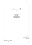
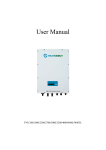
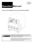
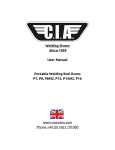
Safety ● The Flux oven sold with this manual should not be used for any purpose other than that for which it was designed. ● Before operating the oven it is advised that this user manual is read and understood by all users. Accidents and potential risks can be reduced by a thorough knowledge of the ovens operations and ideal working environment. ● It is important that the manual is kept in a tidy condition for any future reference, if a manual is misplaced or damaged, a replacement can be obtained from CIA Ovens. ● Do not damage or remove the safety and rating labels from the oven All mineral coated electrodes begin absorbing moisture once they are unpacked. Welding with moist electrodes leads to increase arc spatter, undercutting and poor slag removal. Other side effects include porosity, underbead cracking and generally low grade welds. The range of ovens provides facilities for every application where quality welds are required. NOTE: ELECTRODES MUST ALWAYS be removed from their wrappers or packets prior to heating. Failure to do so will result in an increased risk of fire and moisture not being carried off and being re-absorbed into the coating when the electrodes cool. ● In the event of danger such as fire or overheating it is important that the electrical supply be switched off at the first sight of danger ● Take great care when removing flux from the oven after heating, wear gloves and keep clear of the element(s) which may still be very hot. ● Undergo all operations with general due care and attention Electrical Information To ensure that your CIA product is electrically safe, it is important to ensure that a suitably rated fuse is used in the plug when using the oven. By following simplistic electrical codes of practice such as Ohms law and the Power Triangle, determining the correct and appropriately rated fuse is used. Below is a explanation of these electrical theories: Oven C100 110-220V Single Phase 380V Three Phase Capacity Max Temp Power Output 80 KG 370 3 Elements 4kW 200KG 370 Description C200 380V Three Phase 3 Elements 6.7kW C400 380V Three Phase 400KG 370 6 Elements 13.2kW C400/ C400D 110-220V Single Phase 380V Three Phase 400KG 370 6 Elements 13.2kW Installation The oven is transported in a rigid wooden crate to stop the oven moving around in transit. Be sure to dispose of the crate in an environmentally responsible way. Great care should be taken with the ovens location and operating environment, please consider the following to ensure your CIA Flux Oven is located safely: ● Where possible place the oven on flat or level ground, avoid slanted, uneven and undulating surfaces, or any environment in which the oven could become unstable or fall over completely. ● Use the eyebolts located on the body of the oven to place it in its desired location. ● Do not place the oven in places where it could be subject to draft or high levels of humidity. Once the oven is placed in its optimal location adhere to the following guidelines for an efficient and safe installation: ● Check that the mains electrical supply is suitable for the oven. The voltage and power requirements are given on the rating plate located next to the mains supply cable. ● Connection to the mains electrical supply should be made via a fused isolator switch for a permanent installation. ● It is recommended that the earth lead is connected with provision for some `slack` so that, in the event of the cable coming under stress the earth wire is the last to be affected The colour coding of the mains supply is as follows Single Phase T hree Phase Wire Colour Connection Wire Colour Connection Brown Live Brown Line Conductor 1 Blue Neutral Black Line Conductor 2 Green/Yellow Earth Grey Line Conductor 3 - - Blue Neutral (Where Fitted) - - Green/Yellow Earth Operating Instructions Starting the Oven for the first time: Load the oven with the desired amount of flux Ensure the door is fully shut Check that the power connections are secure Turn the oven on via the main switch and check for power After 10 seconds the thermoregulators are able to be programmed to the desired conditions. Altering the temperature and time set-points In cases where a custom programme is required, please follow the instructions below: 1. 2. 3. 4. 5. a) ADJUSTMENT OF THE HEATING ELEMENTS CONTROL AND SAFETY THERMOREGULATOR (°C heating element) : press and release the key L1 : the L1 led starts flashing, 1SP is displayed for one second , then the value linked to the setpoint appears; press LEFT or RIGHT to change the value ; the new value and the return to normal mode can be saved; the same happens after 10 seconds of inactivity. Press 0/1 to return to normal mode without saving any value. b) ADJUSTMENT OF THE OVEN-ENVIRONMENT THERMOREGULATOR (°C oven- environment) at active “SET POINT” stage ( SP1 or SP2 ). Cycle SP1 (drying): pressing the “P” key (for 1 sec.max.) , the SP1 adjustment is activated; act on UP and DOWN and set the required temperature (400°C max.); enter by pressing the P” key (for max. 1 sec.) After 6 hours (the time is adjustable from MENU as per following description) you can go to: Cycle SP2 (keeping): pressing the “P” key (for 1 sec.max.), the SP2 adjustment is activated; act on UP and DOWN set the required temperature (200°C max.); enter by pressing the “P” key (for 1 second max.) During the programming time checking is halted c) ADJUSTMENT OF THE OVEN-ENVIRONMENT THERMOREGULATOR (°C oven- environment) at inactive “SET-POINT” stage ( SP1 – SP2 ): The programming menu is activated pressing on “P” key for more than 2 seconds. Through UP and DOWN keys, select ‘’OPER’’ and confirm with the ‘’P’’ key. Select by UP/DOWN and choose “SP2”, enter by pressing “P”, 120° (or last programming) appears, select by UP/DOWN until the required value is achieved, enter by pressing “P” key. ( The thermoregulator gets back to start, whether no change is done in 20 seconds) Drying Time Programming (T Lasting) The programming menu is activated pressing on “P” key for more than 2 seconds . Through UP & DOWN keys, select ‘’OPER’’ and confirm with the ‘’P’’ key. ‘’ SP” appears, select by UP /DOWN keys, “] REG” appears, press “P” and time last. appears, press “P” and 6.00 (last programming stated in hours, min.) appears, select by UP/DOWN keys, until the required value is achieved, enter by pressing “P” key. (The thermo regulator gets back to start, if no change is completed within 20 seconds). It is necessary to switch the oven off and switch it on again when you change the parameters to apply them. Suggested temperature settings These are typical temperature settings for the treatment of most welding flux. Always consult the flux manufacturer’s specification for the drying and holding temperature of flux. Operation Time Set Point ‘’1’’ Drying 350-420 Celsius Set Point ‘’2’’ Drying cycle Keeping Timer 4H + 2H 120-150 Celsius Maintenance Plan the routine maintenance when the oven is not in use. Pay attention to the thermocouple feeler, which is connected to the heating element, when the oven is unloaded. Check the oven is always in efficient condition. Check the mains supply cable at regular intervals and, if damaged, replace it immediately. Check the heating elements are clean from flux slags and the temperature sensors are correctly fixed on the heating element. Heating Element Replacement To replace the heating element, proceed as follows: 1.Switch off the mains supply 2.Make sure that the heating element are cool prior to performing maintenance 3.Remove the metal hat shaped cover located on the rear of the oven 4.Disconnect the faulty heating element and replace with a new one having the same properties and sizes. 5.Correctly restore electrical connections 6.Carefully refit the temperature sensor 7.Reassemble the bottom cover on the rear of the oven 8.Switch on the oven via the main power switch for a few minutes to eliminate any possible humidity residual on the new heating element. 9.Switch it off and await about 15 minutes before switching it on again, making the oven operational. This allows the heating element to stabilize The oven is now ready for operation Extraordinary maintenance Periodically check the quality and connection of electrical wires and components, and replace where necessary. In the case of any further problem, please contact your dealer or directly to CIA Ovens who are on hand to help resolve your problem. Part Labels MPS Main Power Switch 3x16/3x25/3x32A ThE Element Thermoregulator ThAT Air temp Thermoregulator IND1 Green ‘’ON’’ signal lamp IND2 White ‘’CONNECTION’’ signal lamp HERCS Element(s) remote control switch HE1HE2HE3 Heating Elements 230V 1500W x C3C6C9Fm2/ 2750W x FmFm1/ 1300W x C100 C200C400D TR 220380/24V Transformer F10F20F30 Fuses 16A (C100)20A (C200)32A (C400(D)) F4050 Fuse 2A F60 Fuse 6A IND3 Red Thermal Pressure signal Lamp SELAB Selector AB Wiring Diagrams C100-C200-C400 C400-D (Dual Controller) Useful Information Model Power (kW) Capacity Kg Internal dimensions (mm) Shipping Weight Kg C100 4 80 530 x 390 x 640 mm 100 C200 6.7 200 690 x 690 x 740 mm 130 C400 13.2 400 (Dual Tank) 1 Controller 690 x 690 x 740 mm 1 tank 225 C400D 13.2 400 (Dual Tank) 2 Controllers 690 x 690 x 740 mm 2 tanks 225 Warranty General conditions CIA guarantees the product mentioned in this manual for a period of 12 (twelve) months from the date of delivery. The warranty is valid for the above mentioned period and only for the parts that will have defect of design or defective material. CIA will give you further instructions for repairing or replacing the complained parts, free of charge. Any transport expenses will be covered by the customer. Limitations CIA Ovens Ltd is not and will not be responsible for: ● ● ● ● ● ● ● Improper use of the oven A use against the national and/or International regulations in force (where applicable) Improper or wrong connection Improper or insufficient care and maintenance Unauthorized modifications and/or services Use of non-original spare parts or non-specific components Partial or total Inobservance of the instructions