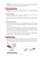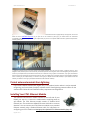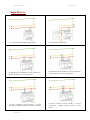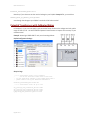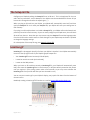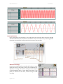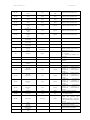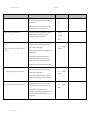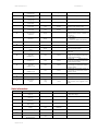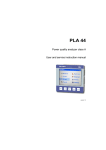
1
PQube User Manual 2.1
Revised Mar-15
®
PQube
Installation & User’s Manual
Firmware Rev 2.1
PSL
Power Standards Lab
2020 Challenger Drive #100
Alameda CA 94501 USA
www.PowerStandards.com
© 2008-2012 Power Standards Lab
Page 1 of 113
PQube User Manual 2.1
Revised Mar-15
WARNING: Death, serious injury, or fire hazard could result from improper connection or
operation of this instrument. Carefully read and understand manual before connecting this
instrument.
AVERTISSEMENT: Si l'instrument est mal connecté, la mort, des blessures graves, ou un
danger d'incendie peuvent s'en suivre. Lisez attentivement le manuel avant de connecter
l'instrument.
WARNUNG: Der falsche Anschluß dieses Gerätes kann Tod, schwere Verletzungen oder
Feuer verursachen. Bevor Sie dieses Instrument anschließen, müssen Sie die Anleitung lesen und
verstanden haben.
ADVERTENCIA: Una conexión incorrecta de este instrumento puede producir la muerte,
lesiones graves y riesgo de incendio. Lea y entienda el manual antes de conectar.
If this equipment is used in a manner not specified by the manufacturer, the protection provided
by the equipment may be impaired. Installation, service, and maintenance of your PQube must
only be done by an expert for electrical installations.
© 2008-2012 Power Standards Lab. All rights reserved. No parts of this document may be copied,
reproduced, or translated to another language without the prior written consent of Power
Standards Laboratory. “PQube” is a registered trademark of Power Standards Lab. “Windows”
“Excel”, and “PowerPoint” are registered trademarks of Microsoft Corporation.
The information contained in this document is subject to change without notice.
PSL MAKES NO WARRANTY OF ANY KIND WITH REGARD TO THIS MATERIAL, INCLUDING, BUT NOT
LIMITED TO, THE IMPLIED WARRANTIES OF MERCHANTABILITY AND FITNESS FOR A PARTICULAR
USE.
PSL shall not be liable for errors contained herein or for incidental or consequential damages in
connection with the furnishing, performance, or use of this material. If you do not accept this
limitation on liability, please return the product to PSL prior to use.
Produced in the United States of America.
Symbol
Meaning
Caution. Consult this manual in all cases where
this symbol is used.
Caution. Risk of electric shock
Alternating current
Alternating current (a.c.) or direct current (d.c.)
Double or Reinforced insulation
Functional earth terminal not relied on for safety
First Release: July 2012
Page 2 of 113
PQube User Manual 2.1
Revised Mar-15
Table of Contents
Table of Contents
3
Introduction
6
What Can Your PQube Do? .......................................................................................................... 6
How Is Your PQube Different?..................................................................................................................................... 7
Applications .................................................................................................................................................................. 8
Choosing Modules ....................................................................................................................... 8
Measure Current, Power, and Energy ......................................................................................................................... 9
Remote Communication .............................................................................................................................................. 9
XCT5 and ETH1 combined into 1 module .................................................................................................................... 9
Power your PQube from 100~240Vac ....................................................................................................................... 10
Measure Temperature and Humidity........................................................................................................................ 10
DC Monitoring ............................................................................................................................................................ 10
Installation
11
Quickstart .................................................................................................................................. 11
General Installation ................................................................................................................... 13
Mount your PQube securely ...................................................................................................................................... 13
PQube instrument power .......................................................................................................................................... 14
Connecting the wires ................................................................................................................................................. 14
Using your PQube with external Potential Transformers......................................................................................... 16
Include overcurrent protection and a disconnecting device .................................................................................... 17
Protect the operator from the hazardous terminals ................................................................................................ 17
Protect antenna terminals from lightning ................................................................................................................. 18
Installing Your ETH1 Ethernet Module ...................................................................................................................... 18
Installing Your PS1 or PS2 Power Supply Module ..................................................................................................... 19
Installing Current Modules ........................................................................................................................................ 19
Wiring Diagrams ........................................................................................................................ 21
Single-Phase L-N ......................................................................................................................................................... 21
Split-Single-Phase L-N-L.............................................................................................................................................. 22
Single-Phase L-L .......................................................................................................................................................... 23
Delta ........................................................................................................................................................................... 24
Wye/Star .................................................................................................................................................................... 25
Wye/Star (continued) ................................................................................................................................................ 26
Overview of connections and controls ...................................................................................................................... 27
Disconnect mains prior to servicing........................................................................................................................... 27
Page 3 of 113
PQube User Manual 2.1
Revised Mar-15
Calibration Information for Your PQube .................................................................................... 27
Setting up your PQube
28
Setting the Date and Time ......................................................................................................................................... 28
Setting Your Languages .............................................................................................................................................. 28
Check your Power Configuration ............................................................................................................................... 28
Setting Your Potential Transformer Ratio ................................................................................................................. 28
Potential Transformers with Calibrated Ratios ......................................................................................................... 29
Setting up Your Optional Current Module ................................................................................. 30
Setting Current Transformer Ratio ............................................................................................................................ 30
Inverting Current Channels ........................................................................................................................................ 30
Calculating Current With a Missing CT ...................................................................................................................... 30
Fix installation errors, simply and easily .................................................................................... 31
Setting Relays for Triggering on Events ...................................................................................... 31
Setting up Your Optional ETH1 Ethernet Module ...................................................................... 32
Network Setup ........................................................................................................................................................... 32
Email Setup................................................................................................................................................................. 32
Web Server Setup ...................................................................................................................................................... 35
FTP Setup .................................................................................................................................................................... 35
Modbus Setup ............................................................................................................................................................ 35
Simple Network Management Protocol (SNMP) ...................................................................................................... 36
The Setup.ini File........................................................................................................................ 37
Location.gif ................................................................................................................................ 37
DC Monitoring ........................................................................................................................... 38
Individual Ratios for each Analog channel ................................................................................................................ 38
DC Power and Energy................................................................................................................................................. 38
Swap AN1 and AN2 in software................................................................................................................................. 38
Customize your Analog channels............................................................................................................................... 38
User Guide
39
Using Your PQube ...................................................................................................................... 39
Your PQube’s Display and User Interface.................................................................................................................. 39
Inserting and Removing Your SD Card ....................................................................................... 44
What Channels Does My PQube Measure? ............................................................................... 44
Standard PQube Channels ......................................................................................................................................... 44
Additional Channels Available With Optional Current Module ............................................................................... 48
Temperature and Humidity ....................................................................................................................................... 49
Page 4 of 113
PQube User Manual 2.1
Revised Mar-15
PQube Recordings...................................................................................................................... 50
Event and Snapshot Recordings ................................................................................................................................ 50
Trends and Statistics Recordings ............................................................................................................................... 56
Trends and Statistics Channels .................................................................................................................................. 57
Changing the configuration during a measurement interval ................................................................................... 59
File Formats ................................................................................................................................................................ 59
Manually Trigger Snapshots or Daily Trends ............................................................................................................. 61
User Counter .............................................................................................................................................................. 61
Getting Data Into and Out of Your PQube ................................................................................. 62
SD Card ....................................................................................................................................................................... 62
ETH1 ............................................................................................................................................................................ 62
Maintenance.............................................................................................................................. 65
Upgrading Your PQube’s Firmware ........................................................................................................................... 65
Turning Off Your PQube ............................................................................................................................................. 65
Replacing your PQube’s battery ................................................................................................................................ 65
Cleaning Instructions.................................................................................................................................................. 65
PQube Specifications
66
Appendix 1: Modbus
71
A brief introduction to Modbus ................................................................................................................................. 71
PQube® Modbus registers ......................................................................................................................................... 71
PQube Modbus Register Table .................................................................................................. 72
Appendix 2 – Setup File Guide
78
PQube Setup............................................................................................................................................................... 78
Configure Event Triggering......................................................................................................................................... 87
Network Configuration .............................................................................................................................................. 95
Setting up your Trends and Statistics ...................................................................................................................... 101
Appendix 3 – Ride-Through Curves
105
STANDARD ............................................................................................................................................................... 105
SEMI F47 ................................................................................................................................................................... 106
Samsung Power Vaccine .......................................................................................................................................... 106
ITIC ............................................................................................................................................................................ 107
CBEMA ...................................................................................................................................................................... 107
MIL-STD 704E ........................................................................................................................................................... 108
MIL-STD 1399 ........................................................................................................................................................... 108
Appendix 4 –MIB Table for SNMP
109
PQube MIB Table ..................................................................................................................... 109
Page 5 of 113
PQube User Manual 2.1
Revised Mar-15
Introduction
What Can Your PQube Do?
Your PQube® is an instrument for monitoring electric power systems.
It is convenient to think of it as a combination of a power disturbance monitor, a power meter, a
power recorder, and a digital camera – it combines the best features of all four.
Your PQube records disturbances on the mains circuit: sags/dips, swells, interruptions, frequency
variations, and disturbances on two analog input channels. It also records impulses, waveform
snapshots, unbalance, flicker, and THD, and trend data (strip charts and cumulative statistics).
When equipped with an optional current sensing module,
your PQube also records current waveforms, RMS amps,
power and carbon. It measures watts, watt-hours, VAR’s,
power factor, and other power-related parameters.
You don’t need any software from PSL to use
your PQube. It records all data on a SD
memory card, which can be read by any
computer. No special software is required – just open the GIF picture files with
standard image programs, or even Microsoft Word® and Microsoft PowerPoint®,
or open the CSV files with any spreadsheet program such as Microsoft Excel® (or
OpenOffice.org Calc if you prefer something free). Configure your PQube with our
free PQube Configurator program, or by editing a text file on the SD card.
It can monitor single-phase or three-phase circuits, at up to 690 VAC phase-to-phase (400 VAC
phase-to-earth), at 50 Hz, 60 Hz, and 400 Hz.
It includes channels for measuring auxiliary voltages – typically 24V AC or 48V DC.
It also has a general-purpose digital input, which you can control with switch contacts or a logic
signal, and a relay contact output, which opens for at least 3 seconds whenever your PQube
detects an event.
It can be directly powered from 24V AC or 24~48V DC, or it can be equipped with an optional PS1
power supply that operates from 100V ~ 240V, 50/60 Hz.
Your PQube also measures and triggers on temperature and humidity at up to two locations, using
optional TH1 temperature-humidity probes.
When equipped with an optional ETH1 Ethernet module, your PQube can automatically send you
e-mails whenever it detects an event. You can send your PQube a new setup file, or even update its
firmware via e-mail. The Ethernet module also includes a web server, an FTP server, and MODBUS
over TCP, giving you even more ways to communicate with your PQube.
Page 6 of 113
PQube User Manual 2.1
Revised Mar-15
How Is Your PQube Different?
There are many power quality meters, energy meters, and energy recorders available. What
makes the PQube stand out from other products?
•
No software. No rental fees. Open data. -- You don’t need any software from PSL to use
the PQube. Do you have a web browser? A text editor? A spreadsheet program like
Microsoft Excel®? That’s all you need! All the data that the PQube records are in open
formats that are easy to understand. You don’t have to buy or lease software from Power
Standards Lab, you don’t have to pay us to see your data, and the files are easy to pass on
to third parties.
•
Friendly data. – When you look at information about your electric power, you don’t want
to spend a lot of time learning to use software to get the view that you want. You simply
want your data organized and presented to your in a format you can understand. Your
PQube presents power quality events, trends, and statistics in formats you can easily use
and lays the data out in a way that’s understandable. Your PQube knows what’s
important.
•
Free firmware updates – From time to time, we offer firmware updates to add new
features to your PQube. Other instrument manufacturers charge for firmware updates, we
don’t.
•
Works out of the box, or configure everything to work for you – With our patent-pending
auto configuration, you can connect your PQube to the power that you want to measure
and the PQube will immediately start recording data. If you don’t like the default settings
you can change almost any setting in the PQube Configurator program, or by editing a text
file on the SD card.
•
Works with or without a network – Do you have an Ethernet network? Use an optional
ETH1 module and get emails when an event occurs, browse the recorded events and
trends with your web browser, or integrate it into your Modbus system. Don’t have a
network? No problem, just walk up to the PQube and take the SD card. You can look at all
the files on any computer (you don’t need software). You don’t need a sophisticated
centralized data collection system to get started. Just connect a PQube and start getting
data right away.
•
Store years of data on standard SD cards. – Your PQube comes with an 8GB SD card which
will store about 4 years’ worth of data based on 2 gigabyte typical usage per year of data.
•
Small size – The PQube is tiny (a little bit bigger than your fist), and that makes it easier to
integrate into your product.
•
Low cost – At Power Standards Lab, we’re experts at building power sensor electronics.
We know how to do it right, and we know how to do it inexpensively. The PQube costs far
less than comparable instruments.
•
It’s everything you need. – Power quality data: dips, swells, frequency variation, and highfrequency impulses. Energy data: kWh, kVAh, and carbon. Trend data: daily, weekly, and
monthly strip charts, cumulative probability and load duration. Why buy multiple meters
when the PQube can do it all?
Page 7 of 113
PQube User Manual 2.1
Revised Mar-15
Applications
Your PQube is ideal for reducing your service costs on sensitive equipment, such as semiconductor
manufacturing equipment and sophisticated medical scanners. By detecting and recording power
disturbances, you can easily and quickly separate intermittent power problems from other
intermittent problems: software bugs, user errors, supply stock problems, etc.
And your PQube is an excellent choice for monitoring the power that feeds industrial controls, such
as automated machinery, robotics, and elevator/lift controls.
You can use your PQube in dozens of other applications: monitoring the power quality at key
accounts, doing national surveys of power quality, safely recording power data for research
projects, understanding why your wind turbine drops off line unexpectedly, and many other
purposes.
Choosing Modules
Your PQube records events, trends, and statistics by monitoring your AC mains voltages. It also
measures two analog input channels for additional signals (for example, the output of a power
supply), a digital input channel, an output relay, and a full color display. Your PQube records all
information to a standard SD memory card.
IMPORTANT: Installation, service, and maintenance of your PQube must only be done by an
expert for electrical installations. 1
1
This is a requirement for Japanese safety standard approvals.
Page 8 of 113
PQube User Manual 2.1
Your PQube clicks together with several optional modules to provide extra features.
modules for your application, you’ll need to answer four simple questions:
Revised Mar-15
To choose
•
Are you interested in measuring current, power, or energy?
•
Do you want to power your PQube from 100~240Vac (50/60Hz)?
•
Are you interested in any of the following: email, a web server, an FTP server, or Modbus
over TCP?
•
Do you want to record the temperature and humidity in addition to everything about the
electric power?
Measure Current, Power, and Energy
Are you interested in measuring current, power, or energy? If so, you’ll need a PQube current
module. There are three versions; please pick the one that is best for you.
XCT4 – External CTs with current secondary outputs
If you already have CTs (Current Transformers) with current outputs, you
can use an XCT4. This module accepts 1-Amp or 5-Amp CT secondaries.
For more information, see the XCT4 Current Module section (page 19).
XCT5 - External CTs with voltage secondary outputs
If you already have CTs with voltage output, or you purchase them from
Power Standards Lab, you can use an XCT5. This module accepts 0.333 Volt,
1 Volt, 5 Volt, or 10 Volt secondaries. This module comes with five current
channels, allowing you to measure all three phase currents, neutral current,
and earth current simultaneously!
CT4 – Current Sensing Module
If you don’t want to use CTs, the CT4 current module might be right for
you. This module is rated for 20 amps and has the CTs built in already.
Just pass the conductors through. For more information, see the CT4
Current Module section (page 19).
Remote Communication
ETH1
Are you interested in any of the following: email, a web server, an FTP
server, or Modbus over TCP? If you need any of these features, you
need an ETH1 Ethernet module. For more information, see the ETH1
section (page 62).
XCT5 and ETH1 combined into 1 module
CTE1
Are you interested in having network capability and measuring current,
but don’t have the space for both an ETH1 module and XCT5 module? Use
a CTE1 module to take advantage of the ETH1 and XCT5 functionality in a
single compact module.
Page 9 of 113
PQube User Manual 2.1
Power your PQube from 100~240Vac
PS1
PS2
Do you want to power your PQube from 100~240Vac (50/60Hz)? If you have
24~48Vdc or 24Vac, you can use your PQube’s internal power supply (just
connect to the power supply screw terminals). If you want to use
100~240Vac, you’ll need an optional PS1 Power supply module.
In addition to powering your PQube from 100 ~ 240VAC (50/60Hz), you can
power external accessories with the PS2’s 24VDC output.
Measure Temperature and Humidity
TH1
Do you want to record the temperature and humidity in addition to
everything about the electric power? You can use up to two TH1
Temperature/Humidity sensors. Measure the local environment or
connect a second sensor with an extension cable and measure the
temperature and humidity at two locations simultaneously. Just plug
them into your PQube and it will start recording data immediately.
DC Monitoring
ATT1
Interested in High Voltage DC Monitoring? Use an ATT1 module. It is
available with a full scale of 600VDC and 1200VDC, and can measure up to
1000VDC and 2000VDC, respectively. Measure 1 differential voltage, or 2
voltages relative to earth.
ATT2
Do you want to monitor both DC voltage and DC current? Use an ATT2
module, it is available with a full scale of 600VDC and can measure up to
1000VDC. The ATT2 module accepts a DC current sensor that is powered by
±15VDC, and has a ±5V nominal output.
Page 10 of 113
Revised Mar-15
PQube User Manual 2.1
Revised Mar-15
Installation
Quickstart
Snap your PQube on to your DIN rail, then snap on and slide together any modules.
Don’t have an ETH1, XCT4, XCT5, CTE1 or CT4 plug-in module? Go to step 3.
a) ETH1 module? Connect your Ethernet cable.
b) CTE1 module? Connect your Ethernet cable to the RJ45 port, and your current transformer
wires to the terminal blocks.
c) XCT4 or XCT5 current interface module? Connect your current transformer to the screw
terminals of your XCT module. Note: You can only install ONE current module (CTE1,
XCT4, XCT5, or CT4) to the PQube.
d) CT4 current sense module? Pass your current carrying conductors through the CT openings.
(a) (b)
(c)
Connect Earth and Mains wires to your PQube.
Page 11 of 113
(d)
PQube User Manual 2.1
Revised Mar-15
Connect 24VAC or 24-48VDC POWER to your PQube, or plug in a PS1 or PS2 Power Supply
module and connect 100~240VAC to it.
or
Use the joystick and pushbutton to navigate through the screens …
… And verify that your voltage and/or current readings are correct. If using AUTO-configuration,
verify that your PQube “locks on” to the correct power configuration and nominal voltage. Very
important: Your PQube requires a min. 30VAC to lock on and start recording data.
Page 12 of 113
PQube User Manual 2.1
Revised Mar-15
Your PQube is recording power quality events and trends on its SD card. If you have a current
transformer module, your PQube is also measuring energy.
General Installation
Mount your PQube securely
Your PQube, and its optional modules, are designed to be mounted on an industry-standard 35mm
DIN rail as rack- or panel-mounted equipment.
The optional PS1 Power Supply module connects to the right side of your PQube. The optional
Ethernet module or current sensing modules connect to the left side of your PQube. Connect them
to your PQube in any order that is convenient. Do not connect multiple current sensing modules.
Only connect one current sensing module, either a CT4, XCT4, XCT5 or CTE1.
In the United States and Canada, the equipment installation shall meet ANSI/NFPA 70, NEC, with
CSA C22.1, CEC, Part I or with both as appropriate. In other countries, follow all local installation
requirements and regulations.
Your PQube’s “enclosure”, as defined in UL/IEC 61010-1, is provided by the installation, and must
be evaluated in the end product.
Page 13 of 113
PQube User Manual 2.1
Revised Mar-15
IMPORTANT: Your PQube must be installed only by an expert for electrical installations 2. The
instrument power screw terminals must be connected to no more than 24Vac +/- 20%, or
24Vdc~48Vdc +/- 20%, supplied by a certified isolating power supply.
PQube instrument power
Your PQube can take its operating power from three different sources: its Power screw terminals
[23][31], its internal Lithium Polymer rechargeable battery, or an optional PS1 Power Supply
module.
Power screw terminals
Your PQube’s Power screw terminals [23][31] accept 24VAC nominal, or 24Vdc~48Vdc nominal.
They are most commonly connected to 24Vdc, 24VAC, or -48Vdc.
Polarity does not matter. Also, your PQube provides a minimum of 150V of transformer-based
isolation between these terminals and all other terminals, eliminating any problems with ground
loops.
Internal Li-Polymer battery
Your PQube’s internal Li-Polymer battery is automatically charged from all the other power
sources. An application-specific chip manages the charging process, paying attention to voltage,
current, and temperature. The battery itself is equipped with an internal high-temperature shutdown circuit.
The battery operating capability depends on the options installed in your PQube, and on the
ambient temperature. In typical tests, the battery can operate your PQube for about one hour.
However, you can choose the operating duration by writing a value in your Setup.ini file. The value
can be set from 1 to 9 minutes (the default is 3 minutes). This guarantees that there will be enough
charge in the battery to record several successive power interruptions.
As the battery ages, its capacity will decline. For maximum performance, it may be necessary to
replace the battery in 5 years. Some normal swelling of the battery may result from high
temperature operation, but this does not interfere with battery performance.
Connecting the wires
Observe the wire size specifications and limitations. All conductors must be stranded copper. All
conductors and insulation systems and crimped devices must be appropriate for the application.
PSL recommends crimped ferrules on stranded wire, or crimped snap-on forked lugs. Tighten the
screw terminals to 0,8 newton-meters (7 inch-pounds) of torque. Observe all voltage ratings and
limits.
2
This is a requirement for Japanese safety standard approvals.
Page 14 of 113
PQube User Manual 2.1
Revised Mar-15
®
For mains connections and current connections, PSL recommends snap-on forked terminals, such as 3M Scotchlok P/N MU186FL or MU14-6FL, or Panduit P10-6lF. For other connections, PSL recommends wire ferrules for stranded wire, such as Panduit
F77 series, for example Panduit F77-6-M.
Figure 1: Your PQube meets all IEC requirements for highfrequency emissions and susceptibility, both conducted and
radiated. For further protection, you can use clamp-on
ferrites on signal cables to minimize radio-frequency
emissions. For example, these are Panasonic
KRCBC160928B and KRCBC130714B.
Conductor characteristics
Figure 2: To minimize emissions with the optional PS1
Power Supply module, optionally use a shielded power
conductor.
Connection
Minimum wire size
PQube terminals
L1, L2, L3, N
[9] [11] [13] [15]
20AWG (0,52 mm )
14 AWG (2.1mm )
PQube Earth terminal
[32]
Wire size used for
L1,L2,L3,N terminals
14 AWG (2.1mm )
Optional
PQube RLY4 terminals
[25] [26]
20AWG (0,52 mm )
All other PQube
terminals
Optional PS1
terminals
20AWG (0,52 mm )
Optional XCT4
terminals
20AWG (0,52 mm )
Optional CT4 passthrough inputs
20AWG (0,52 mm )
Page 15 of 113
2
Maximum wire size
2
2
2
14 AWG (2.1mm )
2
14 AWG (2.1mm )
2
14 AWG (2.1mm )
2
14 AWG (2.1mm )
2
Limited by physical
dimension of passthrough locations:
8.5 mm (0.34”) dia.
20AWG (0,52 mm )
2
2
2
2
Limitations and remarks
Comply with all local safety and installation
requirements and regulations.
Min 600V UL-recognized insulation system required.
These terminals require less than 0,01 amps.
Connection to N (15) is optional. For single phase
monitoring, connect either L1-N or L1-L2 as
appropriate for the mains configuration.
Connect this terminal to a suitable earth connection.
For proper PQube operation, you must connect this
terminal to earth. It is used as a measurement
reference, and as a reference for your PQube’s low
voltage circuits.
Min 600V UL-recognized insulation system required.
Wire size must be adequate for relay contact load.
These terminals are rated at 30 VAC max, 60 Vdc
max, 2 amps max.
Min 600V UL-recognized insulation system required.
Min 600V UL-recognized insulation system required.
Shielded cable recommended for minimizing
emissions.
Ring lugs or snap-on forked terminals are
recommended for CT connections. Self-retaining
screws in terminals may make ring lugs challenging to
install. Wire size must be adequate for 1-amp or 5amp currents. Min 600V UL-recognized insulation
system required
Min 600V UL-recognized insulation system required.
Insulated wire is required!
PQube User Manual 2.1
Maximum voltages
Connection
PQube terminals
L1, L2, L3, N
[9] [11] [13] [15]
Maximum voltage
with respect to Earth
400 Vrms, CAT III
Revised Mar-15
Maximum current
Corresponds to 690 Vrms phase-to-phase on centeredneutral mains systems.
Corresponds to 480Vrms phase-to-phase on centeredneutral mains systems.
All voltage channels must be covered after installation.
up to 300Vrms, CAT
IV
PQube Earth terminal
[32]
Optional PQube RLY4
terminals [25] [26]
All other PQube
terminals
Optional PS1 terminals
N/A
Optional XCT4 terminals
400 Vrms, CAT III
30 Vrms or 60 Vdc
30 Vrms or 60 Vdc
240 Vrms, CAT III
1 amp for XCT4-1A
5 amps for XCT4-5A
up to 300Vrms, CAT
IV
Optional CT4 passthrough inputs
Insulated wire is
required!
Limitations and remarks
400 Vrms, CAT III
up to 300Vrms, CAT
IV
20 amps for CT4-20
50 amps for CT4-50
AC voltage input terminal must be covered after
installation.
Usually connected to external current transformer
secondaries, which provide insulation from mains.
Corresponds to 690 Vrms phase-to-phase on centered
neutral mains systems.
Usually connected to external current transformer
secondaries, which provide insulation from mains.
Corresponds to 480Vrms phase-to-phase on centered
neutral mains systems.
Corresponds to 480Vrms phase-to-phase on centered
neutral mains systems.
Corresponds to 690 Vrms phase-to-phase on centered
neutral mains systems.
Note: “CAT III” means Measurement Category III as defined in UL / IEC 61010-1: “Measurement category III is for
measurements performed in the building installation…. Examples are measurements on distribution boards, circuit-breakers,
wiring, including cables, bus-bars, junction boxes, switches, socket-outlets in the fixed installation, and equipment for industrial
use…”
“CAT IV” means Measurement Category IV as defined in UL / IEC 61010-1: “measurements performed at the source of the lowvoltage installation…. Examples are electricity meters and measurements on primary overcurrent protection devices and ripple
control units.”
Using your PQube with external Potential Transformers
If you want to measure nominal voltages higher than 690 volts, you can connect your PQube
voltage inputs to the secondary windings (low voltage windings) of any standard Potential
Transformer.
In general, the accuracy of your PQube’s voltage measurements are so precise (roughly ±0.1%) that
any accuracy specification will be determined almost entirely by the potential transformer that you
select. If using calibrated potential transformers, you can enter the calibration constants into your
PQube to further improve your accuracy.
For information on configuring your PQube to read correct voltages when using a potential
transformer, see Setting Your Potential Transformer Ratio (page 28).
Page 16 of 113
PQube User Manual 2.1
Revised Mar-15
Include overcurrent protection and a disconnecting device
An external overcurrent protection device, such as a fuse or a circuit breaker, must be installed on
each mains connection. The device shall meet the relevant requirements of IEC 60947-1 and IEC
60947-3, and be suitable for the application.
The overcurrent protection device must be rated between 1 amp (minimum) and 20 amps
(maximum).
Your PQube can share the overcurrent protection device with other loads.
An operator-activated disconnecting device, such as a switch or a circuit breaker, must be installed
on the mains connections. This device must be clearly marked as the disconnecting device for your
PQube, and must be marked to indicate the disconnection function. Do not install your PQube in
such a way that it becomes difficult to operate this disconnecting device. The disconnecting device
must not disconnect the earth connection. The disconnecting device should be installed near your
PQube, within easy reach of the operator.
Protect the operator from the hazardous terminals
IMPORTANT: All high voltage parts must be covered, including the AC power to your PQube.
Install your PQube so that all of the screw terminals are not ACCESSIBLE 3 to the operator. Your
PQube can also be installed without a cover if installed in a lockable IUL 508 control panel.
The operator must be protected from the hazardous screw terminals by a barrier. The screw terminals must be made “not
ACCESSIBLE”, as defined in UL /IEC 61010-1 6.2, using an enclosure or barrier that meets the rigidity requirements of UL /IEC 610101 8.1 and that requires a tool to remove.
3
Accessible, as defined in UL 61010-1, means able to be touched with a standard test finger or test pin, when used as
specified in UL61010-1 6.2.
Page 17 of 113
PQube User Manual 2.1
Revised Mar-15
If you choose to install your PQube in an enclosure, select a UL-listed enclosure that is appropriate for the purpose, such as the
Altech EK series (www.AltechCorp.com). If you plan to use an enclosure of this type, you should review its mechanical
compatibility with any optional features of your PQube that you plan to use: optional USB connections, optional temperaturehumidity probes, etc.
A different example of how to correctly protect your PQube operator from the screw terminals. A 6,35mm (0.25 in) clear
®
Plexiglass sheet, which requires a tool to remove, protects the operator. A rectangular cutout in the Plexiglass gives the operator
access to your PQube controls, the Ethernet connection, etc. Note the 1-amp, 3-phase circuit breaker, at far right, used both as
external overcurrent protection and disconnecting device, near your PQube. The rectangular opening in the Plexiglass should be
74mm x 47mm (for your PQube alone), or 110mm x 47mm (for your PQube and the ETH1 module, or your PQube and the PS1
module), or 146mm x 47mm (for your PQube and both the ETH1 and PS1 modules).
Protect antenna terminals from lightning
If you install a PQube antenna (GPS, Zigbee, etc.) in an outdoor location where it may be exposed
to lightning, you must include a properly installed UL-497C-listed lightning protection device on the
antenna cable. Follow all local installation safety requirements and regulations.
Installing Your ETH1 Ethernet Module
The optional ETH1 Ethernet module connects to the left side of your
PQube; just snap it in. Connect the module before supplying power to
your PQube. The ETH1 Ethernet module contains a standard RJ-45
Ethernet port. The module uses 10BaseT Ethernet with built-in crossover
detection. You can connect your ETH1 Ethernet module to any standard
Ethernet network using a standard Ethernet cable. For information on
configuring your ETH1 module see Setting up Your Optional ETH1 Ethernet Module (page 32).
Page 18 of 113
PQube User Manual 2.1
Revised Mar-15
Installing Your PS1 or PS2 Power Supply Module
The optional PS1 or PS2 Power Supply Module connects to the right side of
your PQube; just snap it in. It accepts any 50/60 Hz single-phase input
between 100Vac and 240Vac nominal. Verify that you are connecting the
line and neutral wires to the correct terminals on the module. The PS1 and
PS2 Power Supply modules contain an internal fuse.
Installing Current Modules
If you want to measure current with your PQube you can install an optional module. Simply plug
the module into the side of your PQube.
PQube current modules provide transformer-based electrical isolation, except for the XCT5-0.333V,
XCT5-01V, XCT5-05V, and XCT5-10V, which take low-voltage inputs.
Note that your PQube makes current measurements with a Crest Factor of 3.5. This means that
your PQube can measure instantaneous currents up to 350% of the nominal rated current (for
example, if you have selected a 300-amp current transformer with a 5-amp secondary, your PQube
will accurately measure up to ±1050 amps instantaneous). This is a very useful feature when
dealing with inrush currents, and currents with high harmonic contents.
When connecting a Current Module, it is important to match the phases to the voltage inputs and
current input (connect the L1 voltage input and the L1 current sensor to the same conductor). This
is important for correct power and energy calculations.
There are three main types of current module, the XCT4 with current inputs, the XCT5 with voltage
inputs, and the CT4. You only need one current module to measure current, power, and energy.
Pick the version that works best for you.
XCT4 Current Module – Current inputs
You can connect external current transformers to your PQube. There
are two versions of the XCT4 module: each will work with a different
type of CT. Make sure you carefully read all safety information
provided by the manufacturer before installing CTs.
If you are using a CT with a current secondary, you can use the XCT41A-00 or the XCT4-5A-00 which have 1 and 5 Amp inputs, respectively.
Your PQube places almost zero burden on the current transformer
(less than 0.1 VA), so you can select almost any current transformer.
XCT5 Current Module – Voltage inputs
If you are using a current sensor that has a voltage output, you can choose between the XCT50.333V-00, XCT5-01V-00, XCT5-05V-00, and XCT5-10V-00 which have 0.333, 1, 5, and 10 Volt
inputs, respectively.
You can use either standard current transformers, or split-core current transformers. Standard
current transformers are generally less expensive, and are often more accurate. Split-core
transformers are much easier to install.
In general, the accuracy of your PQube’s current measurements are so precise (roughly ±0.1%) that
the accuracy of your current measurements will be determined almost entirely by the current
transformer that you select.
CT4 Current Module
Page 19 of 113
PQube User Manual 2.1
Revised Mar-15
If you don’t already have CTs, but you want to measure current, you
can use the optional CT4 module. It has the CTs already built in and
ready to use.
The CT4 module is rated for 20A full scale. It accepts conductors up to
0.34 inches (8,6mm) in diameter. 600V, UL-recognized insulation is
required.
Page 20 of 113
PQube User Manual 2.1
Revised Mar-15
Wiring Diagrams
Single-Phase L-N
(a) PQube monitors complete Voltage Quality
(c) With XCT4 Current Module, 1 current transformer
Page 21 of 113
(b) With CT4 Current Module
(d) With XCT5/CTE1 Current Module, 1 current
transformer
PQube User Manual 2.1
Revised Mar-15
Split-Single-Phase L-N-L
(b) With CT4 Current Module
(a) PQube monitors complete Voltage Quality
(c) With XCT4 Current Module, 2 current
transformers
(e) With XCT4 Current Module, 3 current
transformers
Page 22 of 113
(d) With XCT5/CTE1 Current Module, 2 current
transformers
(f) With XCT5/CTE1 Current Module, 4 current
transformers
PQube User Manual 2.1
Revised Mar-15
Single-Phase L-L
(a) PQube monitors complete Voltage Quality
(c) With XCT4 Current Module, 1 current transformer –
PQube calculates current on other phase
(e) With XCT5/CTE1 Current Module, 1 current
transformer – PQube calculates current on other phase
Page 23 of 113
(b) With CT4 Current Module
(d) With XCT4 Current Module, 2 current transformers
– PQube measures current on both phases
(f) With XCT5/CTE1 Current Module, 2 current
transformers – PQube measures current on both
phases
PQube User Manual 2.1
Revised Mar-15
Delta
(a) PQube monitors complete Voltage Quality
(c) With XCT4 Current Module, 2 current transformers
– PQube calculates current on third phase
(e) With XCT5/CTE1 Current Module, 2 current
transformers – PQube calculates current on third phase
Page 24 of 113
(b) With CT4 Current Module
(d) With XCT4 Current Module, 3 current transformers
– PQube measures current on all phases
(f) With XCT5/CTE1 Current Module, 3 current
transformers – PQube measures current on all phases
PQube User Manual 2.1
Revised Mar-15
Wye/Star
(a) PQube monitors complete Voltage Quality
(c) With XCT4 Current Module, 3 current transformers
– PQube calculates current on neutral conductor
Page 25 of 113
(b) With CT4 Current Module
(d) With XCT4 Current Module, 4 current transformers
– PQube measures current on phase and neutral
conductors
PQube User Manual 2.1
Revised Mar-15
Wye/Star (continued)
(e) With XCT5/CTE1 Current Module, 3 current
transformers – PQube calculates current on neutral
conductor
(g) With XCT5/CTE1 Current Module, 5 current
transformers – PQube measures Earth conductor
current
Page 26 of 113
(f) With XCT5/CTE1 Current Module, 4 current
transformers – PQube measures current on phase and
neutral conductors
(h) With XCT5/CTE1 Current Module, 5 current
transformers – Net Earth Current measurement
PQube User Manual 2.1
Revised Mar-15
Overview of connections and controls
A
Battery compartment latch
I
B
SD memory card and adjacent LED
J
C
Select button
K
D
Joystick. Click like a button to return to
main menu.
L
E
Heartbeat LED
M
F
Temperature/humidity probe inputs.
Optically isolated from local earth.
N
G
H
L1, L2, L3 voltage inputs. 690Vrms max
phase-to-phase (equivalent to 400Vrms
phase-to-earth)
Neutral terminal – optional connection
P
USB port. Optically isolated from local earth.
Factory use for Rev 1.2 firmware; user access in free
future firmware upgrades.
Digital input. 60-volt tolerant. 1.5-volt threshold.
Wetted with 5.4V at 3 microamps.
Power inputs. 24VAC, or 24VDC to 48VDC (either
polarity) nominal. 15VA max.
Earth – functional. Used as the reference voltage.
Analog inputs. Maximum ±60V to earth. Can be used
as differential inputs.
Signal relay outputs. One is standard on all PQubes.
Two more signal relay outputs are available as a
factory-installed RLY option.
Relay contact output rated at 30VAC, 60VDC, 2 amps,
- included in factory-installed RLY option.
Disconnect mains prior to servicing
Always disconnect all mains connections, and verify disconnections, prior to servicing.
Calibration Information for Your PQube
Every PQube is calibrated and traced to NIST at the factory. You can download a free NIST trace
certificate that contains the specific calibration information for your PQube by entering your
PQube’s serial number at www.powerstandards.com/CalibCerts.htm.
Page 27 of 113
PQube User Manual 2.1
Revised Mar-15
Setting up your PQube
Your PQube will work right out of the box. Simply follow the Quickstart Guide (page 11) and your
PQube will begin recording data immediately. The default settings will work for most applications,
but if you have special requirements you may need to change a few settings. Don’t worry, it’s an
easy process.
Setting the Date and Time
You can set the time and date via your PQube’s display. For information on how to
use your PQube’s display, see Your PQube’s Display and User Interface (page 39).
Go to the configuration menu and scroll to the Date/Time screen. Press the select
button and then use the joystick to set the date and time.
Setting the date and time is important because all of the output files your PQube produces include
a time stamp.
Note that if you have an ETH1 Ethernet module and you are using the SNTP feature (off by default),
your PQube will override any changes you make to the date and time.
Setting Your Languages
In previous firmware versions, you set the language at the Languages screen on
the PQube display.
In Firmware 1.4 and newer, you can specify up to two languages to be used in
the PQube at any time in your setup file. Setting languages remotely is now
possible, and the selected language(s) remain even after a firmware update.
PQube_Primary_Language=English-American
PQube_Secondary_Language=None
Check your Power Configuration
Everytime your PQube resets or starts up, make sure your PQube “locks” onto
the appropriate power configuration, nominal voltage, and nominal frequency.
This is important for proper event detection and data recording. Your PQube
will not begin recording until it has locked onto the power configuration.
If you are using your PQube for DC monitoring only, and do not wish to record AC voltage, you can
set your Power Configuration to “NONE” in your setup file.
Setting Your Potential Transformer Ratio
If you are using Potential Transformers (PT) to monitor voltages above 690Vac Phase-to-Phase
(400Vac Phase-to-Earth) you can tell your PQube about the ratio to use to calculate the measured
voltage. For example, to use your PQube on a 24 kilovolt distribution system, you might use a
100:1 potential transformer to reduce the 24 kilovolts to 240 volts. In your PQube’s Setup.ini file,
you would set
Potential_Transformer_Ratio=24000:240
Or, if you prefer, you could set
Page 28 of 113
PQube User Manual 2.1
Revised Mar-15
Potential_Transformer_Ratio=100:1
Note that, if you choose to set the nominal voltage in your PQube’s Setup.ini file, you would set
Nominal_Phase_To_Neutral_Voltage=24000
even though the voltage at your PQube’s terminals is 240 volts nominal.
Potential Transformers with Calibrated Ratios
In Firmware 2.1, you can now apply a gain correction factor for the mains voltage terminals, with a
range of 0.95 to 1.05. Use with calibrated potential transformers to improve the accuracy of your
measurements!
Example: Assuming a 10000:100 PT ratio, use the settings below:
PQube Configurator Settings:
Setup.ini tags
; ------ Valid values: from 1:1 up to 500000:1
;
You can use fractional values such as 1250.5:120
;
If your application requires a ratio higher than 10000:1
;
please contact factory for additional information
Potential_Transformer_Ratio=10000:100
; ------ Valid values: from 0.95 up to 1.05
L1_E_Voltage_Gain_Calibration_Factor=0.9995
L2_E_Voltage_Gain_Calibration_Factor=1.0251
L3_E_Voltage_Gain_Calibration_Factor=1.0087
N_E_Voltage_Gain_Calibration_Factor=1.0000
Page 29 of 113
PQube User Manual 2.1
Revised Mar-15
Setting up Your Optional Current Module
Setting Current Transformer Ratio
If you are using a CT4 current sensing module, you don’t need to set a CT ratio – your PQube will
set it automatically.
If you are using an XCT4 or XCT5 current sensing module, you will need to set the CT ratio so that
your PQube can correctly display the amount of current, as well as correctly calculate power and
energy usage.
For example, to use your PQube on a system with 200 amps flowing in the power conductors, you
might choose current transformers rated at 300 amps, with a 5-amp secondary. In your PQube’s
Setup.ini file, you would set
Current_Transformer_Ratio=300:5
If you have a current transformer with voltage output, simply enter the primary current and
secondary voltage into your CT ratio. For example, if you have a current transformer rated at 300
amps, with 0.333V secondary, then you would set
Current_Transformer_Ratio=300:0.333
Inverting Current Channels
During installation, it is easy to make a mistake in your current transformer connections, either by
reversing the secondary connections (when using an XCT4 or XCT5) or by feeding the main power
conductor through your current transformer backwards (when using a CT4, XCT4 or XCT5).
You will know when the current transformers are installed backwards by looking at your power
(watts) readings. If you are expecting positive watts values and you are getting negative watts (or
vice versa), then you know your current transformers need to be inverted.
Of course, you can always correct your wiring; but an easier alternative is to use your PQube’s
Setup.ini file to invert one or more of your current channels. If you realize that you have installed
your L2 current transformer backwards, you can fix this easily:
Invert_L1_Current_Channel=OFF
Invert_L2_Current_Channel=ON
Invert_L3_Current_Channel=OFF
Invert_N_Current_Channel=OFF
Why Bother?
It is important to correctly connect your CTs (or use the method above to correct a wiring
error). Power (watt) calculations are made by multiplying the instantaneous current by the
instantaneous voltage. If one or more of your current transformers is incorrectly set up,
your PQube will calculate negative power for that phase.
Calculating Current With a Missing CT
You do not need to connect CTs to all of the conductors that you want to monitor. When current
flows through a system, the net current is always zero. Because of this, you can connect one fewer
CT than you have conductors (for a delta system, you only need two CTs, for a wye/star system you
only need 3 CTs, and you must calculate the Neutral current). Your PQube can calculate the
Page 30 of 113
PQube User Manual 2.1
Revised Mar-15
current in the missing CT. Note that if you calculate the current in a missing CT, your PQube will
incorrectly show any earth current as flowing in the calculated phase.
If you want to use this feature, change the Calculate_Current_Channel setting in the Setup.ini file.
Fix installation errors, simply and easily
During installation, it is easy to make mistakes: maybe you accidentally wired your conductors to
the wrong screw terminals, . Of course, you can always correct your wiring; but it’s easier to use
your PQube’s Setup.ini file to swap the phase connections to the appropriate inputs. You can do
this for the voltage and current inputs. For example, if you realize that L2 has been installed on the
L3 input, you can fix this easily:
L1_Input_Connected_To=L1
L2_Input_Connected_To=L3
L3_Input_Connected_To=L2
N_Input_Connected_To=N
L1_Amps_Input_Connected_To=L1
L2_Amps_Input_Connected_To=L3
L3_Amps_Input_Connected_To=L2
N_Amps_Input_Connected_To=N
E_Amps_Input_Connected_To=E
NOTE: When phase swapping, remember that your PQube will not lock on and begin recording
until either the L1-E or L2-E voltage exceeds 30 volts.
Setting Relays for Triggering on Events
The PQube triggers for many types of events. You can choose which of these events will open one
or more relays. Each relay will remain open for 3 seconds or the event duration, whichever is
longer. To change the relay settings, edit the [Event_Relay_Trigger] section. See Appendix 2.
Here are a few simple rules:
•
You can connect any event to any relay.
•
One relay may be connected to multiple events, and any event can be connected to
multiple relays.
•
RLY1 is standard. RLY2, RLY3, and RLY4 are included in the factory-installed RLY option.
•
Enter 1, 2, 3, 4 (or any combination of those numbers) into the relay-event tags to attach
that relay to that event.
•
Enter OFF if you don’t want that event to trigger a relay.
Example: to trigger RLY1 when a Voltage Dip or Swell occurs, set the following relay-event tags:
Trigger_Relay_On_Dip=1
Trigger_Relay_On_Swell=1
Example: to trigger RLY1 and RLY3 when an interruption occurs, set the following relay-event tags:
Trigger_Relay_On_Interruption=13
By default, all relay-event tags are set to OFF. This means no relays will be triggered on events.
Page 31 of 113
PQube User Manual 2.1
Revised Mar-15
Setting up Your Optional ETH1 Ethernet Module
Your ETH1 module requires some configuration before you can begin using it. To configure your
ETH1 module, you need to make a few changes to the Setup.ini file on your SD card. Network
Setup is required to use your ETH1 Ethernet Module. The other sections are optional.
Network Setup
To set up your network connection, you may need to change the
IP_Address_Method setting in the Setup.ini file
Your PQube supports two different methods to get network information.
DHCP is the automatic method used on most modern networks and the
default for your PQube. If your network supports DHCP and you use the
Use_DHCP setting, simply plug in your PQube and it will get the network configuration automatically.
If your network doesn’t support DHCP, change this setting to Use_Fixed_IP and fill out the [Fixed_IP]
section.
Your PQube displays its IP address when connected to a network. This allows you to easily access
your PQube’s Web Server without searching for your IP address elsewhere. This is useful if you are
using DHCP.
Email Setup
Creating an e-mail account for your PQube
Your PQube needs its own email account in order to send email. This is because your PQube is an
email client, just like your computer.
PQube.com email address
Your PQube comes with its own PQube.com email account! By default, all of the email server
information is already filled out for you.
If you need to re-enter your PQube.com email information, follow these steps:
•
Go to the Email & Filter tab in the PQube Configurator program
•
Enter your PQube’s serial number in the PQube Serial Number field.
•
Click the Generate PQube.com e-mail account button and the program will automatically
fill out your email server settings.
Page 32 of 113
PQube User Manual 2.1
Revised Mar-15
Your serial number can be found under the barcode on the rear label, or in the Logs filename.
OR
Creating an email account with your own domain
If you are unable to use the default PQube.com email account, you can create an email account for
your PQube using your own domain. You will need to give your email system administrator some
information, have him or her set up an account for your PQube, and then fill in the
[Email_Server_Settings] section of the Setup.ini file on your SD card.
SMTP vs. POP
Simple Mail Transfer Protocol (SMTP) is the standard protocol for sending email while Post
Office Protocol (POP) is the standard protocol for receiving email.
Setup Configuration
Please tell your System Administrator that:
•
Your PQube is a standard e-mail client.
•
For outgoing mail, your PQube supports plain-text authentication, Cram-MD5, or MD5Digest login.
•
For incoming mail, your PQube supports plain-text authentication, Cram-MD5, MD5Digest, USER-PASS, or APOP login.
•
Ask your System Administrator to set up an e-mail account, and get the following
information from them:
SMTP Server: __________________________ Port: _______
POP Server: ___________________________ Port: _______
PQube e-mail address: _________________________
PQube e-mail user name: _______________________
PQube e-mail password: ________________________
•
Use this information to fill in your Setup.ini file.
WARNING
Do not assign your personal email address to your PQube. Your PQube must
have its own dedicated email address that it can use to send and receive email.
Power Standards Lab is not responsible for any loss of data.
Page 33 of 113
PQube User Manual 2.1
Revised Mar-15
Specify up to 10 email recipients
In the [Outgoing_Email] section, tell your PQube who to send emails to under the Email_To_1 field.
You may enter up to 10 total email addresses to receive emails from the PQube.
Sending a test e-mail from your PQube
After you have set up your PQube to use email, it is a good idea to send a test e-mail from your
PQube. Use the joystick to go to the “Send test e-mail” screen, just to the left of your
“Configuration” menu, and select it. If your PQube sends an e-mail successfully, you will see a
green check mark.
Click the button to send a test
email
The email
successfully
was
sent
There was an error sending the
email
If your PQube could not send an e-mail, you will see an ERR number on the screen. The error
number corresponds to one of the following problems:
ERR 1:
ERR 4:
ERR 6:
ERR 7:
ERR 8:
ERR 9:
ERR 10:
ERR 11:
ERR 12:
ERR 13:
ERR 14:
ERR 15:
ERR 16:
ERR 17:
ERR 18:
ERR 19:
ERR 20:
You don’t have an Ethernet Module with compatible firmware, or it’s not attached to your PQube properly.
PQube sending e-mail: Your PQube had a problem opening the e-mail body file.
PQube sending e-mail: No network connection is available. Check your Ethernet cable and router, and
check your network settings in your Setup.ini file.
PQube sending e-mail: Problem connecting to your e-mail SMTP server. Check that you have the correct
SMTP server name in your Setup.ini file.
PQube sending e-mail: Your PQube successfully connected to your e-mail SMTP server, but the
authentication process failed. Check that you have the correct password, and e-mail address, and that your
SMTP e-mail server supports one of the following authentication methods: plain text, CRAM MD5, MD5
Digest.
PQube sending e-mail: Your PQube had a problem opening an attachment file.
PQube sending e-mail: Error while receiving a reply from your e-mail SMTP server (Your PQube was
expecting data from your SMTP server, but PQube never received the data.)
PQube sending e-mail: E-mail rejected by your SMTP server (Your PQube transmitted the email, and the
SMTP server got the email, but the SMTP server rejected the email for some reason.)
PQube sending e-mail: response error while transmitting to your e-mail SMTP server (Your PQube
connected to your SMTP server, but there was an error sending data to your server).
Domain Name Server error (Your PQube couldn't connect to the Domain Name Server you specified, or
there was an error during DNS transmission, or a bad response from DNS.)
The Domain Name Server says that the domain name does not exist. Check the POP and SMTP and SNTP
servers that you specified in your Setup.ini file.
Your PQube recognizes that an ETH1 Ethernet module is connected, but it is unable to communicate with it.
Your ETH1 may be starting up, and may not be ready yet – try again in a few seconds. If the problem
persists, you may have a mis-match between your PQube firmware and your ETH1 firmware. Upgrade your
PQube firmware.
PQube sending e-mail: the “To:” field or the “From:” field is blank.
PQube receiving e-mail: your POP server caused a Domain Name Server error. Check the POP server that
you specified in your Setup.ini file.
PQube receiving e-mail: Unable to connect to your POP server. Check the POP server that you specified in
your Setup.ini file.
PQube receiving e-mail: POP server authentication failed. Check the POP server that you specified in your
Setup.ini file. Check that you have the correct password, and e-mail address, and that the e-mail server
supports one of the following authentication methods: plain text, CRAM MD5, MD5 Digest.
PQube receiving e-mail: Checking POP server inbox failed. Your PQube connected to your POP server, and
Page 34 of 113
PQube User Manual 2.1
ERR 21:
ERR 254:
Revised Mar-15
your POP server accepted your PQube’s authentication, but for some reason refused to disclose the inbox
contents.
PQube receiving e-mail: Error retrieving a message from your POP server inbox. Your PQube connected to
your POP server, and your POP server accepted your PQube’s uthentication, and your POP server provide
the list of inbox contents, but for some reason the transfer of a message from your POP server to your
PQube failed.
Unknown e-mail error.
Web Server Setup
Your option ETH1 module includes a web
server. When you can type the IP address of
your PQube into your web browser, you will
see a web site that contains all of the
information that your PQube has recorded, as
well as real-time meters and status
information.
The web server is enabled by default and uses
the default HTTP port 80. This means that you
shouldn’t need to change any settings to use
the web server. If you need to use a different
port, you can change the Web_Server_port setting
in the Setup.ini file on your SD card.
For information on how to use your PQube’s Web Server, see the Web section (page 64).
FTP Setup
Your PQube contains a FTP server that you can use to get files from your SD card. FTP (File Transfer
Protocol) is a simple system used for transferring files between two computers that are connected
by a network. The FTP server is enabled by default, you can enable it by changing the FTP_Server
setting the Setup.ini file to ON. You can also change the login and password for your FTP server by
changing the FTP_User_Name and FTP_Password settings. For information on connecting to the FTP
server see the FTP section (page 64).
Modbus Setup
Your ETH1 Ethernet module contains a Modbus-over-TCP slave device that you can use to read
meters and determine when new event or trend recordings are available. You can set the Modbus
TCP port by changing the Modbus_TCP_port setting in the Setup.ini file on the SD card of your PQube.
You can also set the base address of the registers by changing the Modbus_Register_Start_Address
setting.
Configure your Modbus client using the following settings:
Mode = TCP
“2 byte ID” disabled
Function code = 4
Minus offset = 0
Registers should be represented as 32 bit float except where noted.
Page 35 of 113
PQube User Manual 2.1
Revised Mar-15
NOTE: Under normal operation, your PQube will update all of its registers approximately once per
second. However, you may experience delayed response times while your PQube is generating
files for events and trends. These response times can range from a few seconds, up to several
minutes, depending on which parameters are being recorded.
For a description of the available registers, see Appendix 1 (page 71).
Simple Network Management Protocol (SNMP)
A beta version of SNMP is included in Firmware 2.0. SNMP is a common meter reading protocol
that is used in data centers worldwide. For easy SNMP installation, a PQube MIB file is included
with 1.4 release files.
Use the following information to connect to your PQube:
SNMP port: 161
Get community string: pqube
Set community string: pqube
For a description of the available values in the MIB file, see Appendix 4 (page 109).
Page 36 of 113
PQube User Manual 2.1
Revised Mar-15
The Setup.ini File
Configure your PQube by editing the Setup.ini file on its SD card. This is a simple text file. You can
edit it with any text editor, such as Notepad. Your PQube uses the standard INI file format. All you
have to do is change the text after the equals signs ( = ).
When you plug an SD card into your PQube, your PQube will automatically reset itself, and then
read your Setup.ini file. As it reads your Setup.ini file, your PQube will store your settings into its
flash memory.
If you plug in an SD card that does not include a Setup.ini file, your PQube will use the Setup that it
previously stored in its flash memory. So you can easily configure your PQube once, then use blank
SD cards from then on. Note that you may want to copy the Setup.ini file and the language packs
from the old SD card to make it easier to make changes to your PQube setup and make it possible
to change the language settings.
For a description of the setup file tags, see Appendix 2 (page 78).
Location.gif
Location.gif is a photograph (usually) of where your PQube is installed. Your PQube automatically
inserts it at the top right corner of your PQube’s graphic output files.
−
Your Location.gif file must be exactly 128 x 96 pixels;
−
it must be normal row order (not interlaced);
−
it must use the Web palette.
When you insert an SD card that contains a Location.gif file, your PQube will automatically reset
itself, then store the Location.gif into its flash memory. It will permanently remember this picture
until you replace it. (The storing process takes a few seconds, so you may want to delete the
Location.gif file from your SD card after you have inserted it once.)
You can see your Location.gif on your PQube’s display, one joystick click down from the bottom of
the main menu.
Need help creating a Location.gif file? Send us an e-mail at [email protected] .
The locaton.gif picture appears in GIF graph output files.
Page 37 of 113
PQube User Manual 2.1
Revised Mar-15
DC Monitoring
With the new ATT2 module, you can monitor DC Current, DC
Power, and DC Energy with your PQube.
Individual Ratios for each Analog channel
You can specify a separate ratio for the AN1-E channel and AN2-E channel. This is useful for
measuring DC Voltage on AN1-E and DC Current on AN2-E. Edit your setup file and navigate to the
[Analog_Ratios] section of your setup file. For example, if you have an ATT2-600V module with
50A:4V DC current sensor, use the following values:
; -- Valid values: from 1:1 up to 10000:1. You can use fractional values.
AN1-E_Channel_Ratio=100:1
AN2-E_Channel_Ratio=50:4
DC Power and Energy
Your PQube can multiply the AN1-E channel by the AN2-E channel to display DC Power. Connect
your DC voltage source to AN1-E and the output of your DC current sensor to AN2-E, and your
PQube will calculate the DC Power and Energy. Navigate to the [Analog_Ratios] section of your
setup file and edit the following tag:
; ------ Valid Values: ON OFF
;
AN Energy Mode assumes that AN1 is voltage and AN2 is current,
;
and turns on AN power and energy measurements.
;
Turn this tag ON if using an optional ATT2 module.
AN_Energy_Mode=ON
Swap AN1 and AN2 in software
You can swap the AN1 and AN2 connections in your setup file, eliminating the need to physically
swap the wires if they have been improperly installed.
; ------ Use this section to correct an installation error.
;
Valid values: ON, OFF
Swap_AN1_And_AN2_Connections=ON
Customize your Analog channels
You can customize the name of the AN1-E channel and AN2-E channel, and you can specify the
measurement units.
; ------ Use this section of tags to customize the names and units of
your analog channels.
; Analog energy mode does not have to be on for this.
; Valid names can be up to 5 characters.
; Valid values for units are "V", "A", "W", "DEG", "%", "NONE"
Analog_1_Channel_Name="DCV"
Analog_1_Channel_Unit="V"
Analog_2_Channel_Name="DCA"
Analog_2_Channel_Unit="A"
Page 38 of 113
PQube User Manual 2.1
Revised Mar-15
User Guide
Using Your PQube
Your PQube’s Display and User Interface
Joystick and button
Use the joystick (B) on the front of your PQube to navigate through the
displays.
Gently push down on the joystick (B) like a button to return to the Main
Menu. Click the button (A) to make a selection.
To force your PQube to reset, hold the button (A) down for 10 seconds.
The PQube Display
Use the joystick on the front of your PQube to navigate through these screens. Use the select
button to choose an item outlined by an orange
box.
Page 39 of 113
PQube User Manual 2.1
Configuration
Revised Mar-15
Language: Language 1 sets your PQube’s main language, which is used for all of these
screens and the GIF output graphs. Language 2, if you choose one, sets the second
language on GIF output graphs. This can be useful if you expect to discuss these graphs with
an engineer who reads another language.
Power configuration: This screen shows you the power configuration that your PQube is
using. If your PQube is hunting for the correct power configuration, this screen will cycle
through the various possible configurations until your PQube locks onto the correct
configuration. Your PQube knows roughly 1,000 different possible power configurations
used around the world, and can identify the correct configuration approximately 10
seconds after power has been applied to the terminals.
Vectors: Use this screen to verify that your voltage and current inputs are wired up
correctly. Full scale voltage is determined by the nominal voltage found when the PQube
locks onto the power configuration. The vertical bar on the right represents the largest
phase magnitude of current. Its range is from zero amps to the value specified by the
Max_Current_of_Interest_in_Amps tag in the Setup.ini file. (By default, it is set to the
value shown on your current module, multiplied by the current transformer ratio specified
in the Setup.ini tag Current_Transformer_Ratio).
Date/time: Set your PQube’s internal clock-calendar. Your PQube will automatically set the
correct day of week. If you have an ETH1 Ethernet Module, and you have enabled SNTP in
your Setup.ini file, your PQube will automatically set its clock-calendar to UTC.
Trigger: Use this screen to tr igger Snapshot files of your power, or to trigger Daily Trend
and Statistics files. Use the joystick to choose, and press the Select button to begin
generating the files. Snapshots will take about 5 minutes, and trends will take longer,
depending on how much data you have recorded..
Test e-mail: Press the select button to send a test e-mail. If your e-mail succeeds, you will
get a green check mark. If your e-mail does not go through, you will see a red X with an
error message. See WARNING
Do not assign your personal email address to your PQube. Your PQube must have its own
dedicated email address that it can use to send and receive email. Power Standards Lab
is not responsible for any loss of data.
Specify up to 10 email recipients
In the [Outgoing_Email] section, tell your PQube who to send emails to under the
Email_To_1 field. You may enter up to 10 total email addresses to receive emails from the
PQube.
Sending a test e-mail from your PQube (page 34) for more information.
Network: Your PQube’s IP address and link speed can be found on this screen. This is
useful if you have a dynamic IP address. It is also useful for troubleshooting connectivity
issues.
Page 40 of 113
PQube User Manual 2.1
Revised Mar-15
Meters
L-L voltage meters, L-N voltage meters: These are line-to-line, line-to-neutral, and neutralto-earth true-RMS voltmeters. Different meters will show on these screens, depending on
your power configuration. (For example, if the power configuration is “delta”, there will not
be any L-N meters, because there is no neutral conductor.) If you have set a potential
transformer ratio in your Setup.ini file, then these meters will use that ratio, so these
meters will sometimes show their values in kilovolts or even megavolts.
Frequency: This is a frequency meter. It is phase-locked to either L1-E or L2-E, depending
on which channel has the best signal. It measures frequency by timing the zero-crossings,
with a 5-pole analog low-pass filter and a 64-cycle digital low-pass filter.
AN/DIG1: The AN meters show the RMS voltage (equivalent to DC voltage for DC signals)
for the AN1 screw terminal to earth, AN2 screw terminal to earth, and AN1-to-AN2
differential voltage. The DIG1 meter shows the average value of the DIG1 digital input
screw terminal with respect to earth, averaged over one cycle – useful when the DIG1
signal is changing rapidly, because it will show the duty cycle of the DIG1 signal.
AN/DIG1 (AN_Energy_Mode only): With an ATT2 module, your PQube can monitor High
Voltage DC systems. After you have enabled the AN_Energy_Mode tag in your setup file,
AN1-E becomes ANV (DC voltage) and AN2-E becomes ANA (DC current).
A new screen also appears with DC Power and Energy. AN1-AN2 is replaced with
AN-Power, which is the product of the DC voltage and DC current channels. DC Energy is
also displayed here, and it can be reset from this screen.
Probe2 / Probe 1: These meters show the temperature and humidity of the two TH1
temperature-humidity probes. If one or both probes are not plugged in, the meters will
show “--“.
Current: These meters show the true-RMS current. They only appear if you have plugged in
an optional XCT4 or XCT5 current transformer interface module, or a CT4 current sensing
module. If you have set a current transformer ratio in your Setup.ini file, then these meters
will use that ratio, so these meters will sometimes show their values in kilo-amps or even
mega-amps. Different meters will show on this screen, depending on your power
configuration. (For example, if the power configuration is “delta”, this screen will not show
a neutral current meter, because there is no neutral conductor in delta power.)
Current: This screen is a continuation of the previous screen above. It shows the true-RMS
current on the earth conductor. You can choose in your Setup.ini file to calculate net
current from phase and neutral current; or you can measure it with a CT, either on the
earth conductor or with a net-current CT.
Page 41 of 113
PQube User Manual 2.1
Revised Mar-15
Distortion: These meters show the Total Harmonic Distortion (THD) of the voltage and
Total Demand Distortion (IEEE 519 TDD) of the current (if you have an optional current
sensing module installed).
Unbalance: These meters show the voltage unbalance and the current unbalance (if you
have an optional current sensing module installed). You choose in your Setup.ini file
whether your PQube calculates unbalance using the ANSI C84.1 method, or the IEC
method, or the GB method.
Flicker: These meters show flicker (IEC 61000-4-15). Pinst is the instantaneous flicker value
for Incandescent Flicker in IEC 61000-4-15. PST is the short term flicker, a statistical analysis
of Pinst after 10 minutes, synchronized to real-time clock. PLT is the mean value of Pinst over
previous 2 hours, synchronized to real-time clock.
Power: These are the true power readings, and they correctly handle harmonics (distorted
voltages and distorted currents). If you have set a current transformer ratio and/or
potential transformer ratio in your Setup.ini file, then these meters will use those ratios, so
these meters can show their values in kilowatts, megawatts, or even gigawatts.
Energy: These three meters show the total energy, apparent energy, and carbon since the
last reset of these meters. You can reset these meters by holding down the select button
for 3 seconds. The date of the last reset will appear on the screen. You can reset these
meters by holding down the select button for 3 seconds. The date of the last reset will
appear on the screen.
Energy: Access this screen by moving the joystick down from the Energy screen above.
Here, you can view energy in large digits specified in ANSI C12.20.
Carbon: This meter shows the intensity of carbon dioxide output, based roughly from the
EPA’s measurements for typical California, USA values. You may edit these values in the
Setup.ini file as necessary.
Peak amps: These three meters show the cycle-by-cycle highest RMS amps; the 1-minute
interval with the highest RMS amps; and the N-minute interval with the highest RMS amps.
(The highest RMS amps value is determined by looking at the highest among all of the
active phase conductors. It excludes the neutral conductor.) The N-minute reading is
usually set to 15 minutes, but you can set it to a value between 3 minutes and 60 minutes
in your Setup.ini file. The 1-minute and N-minute readings are automatically synchronized
to your PQube’s real time clock. These readings can be useful for evaluating inrush current
and circuit breaker settings, and for sizing power conditioning devices such as UPS and
voltage regulating transformers. You can reset these meters by holding down the select
button for 3 seconds. The date of the last reset will appear on the screen.
Page 42 of 113
PQube User Manual 2.1
Revised Mar-15
Peak demand: These three meters show the cycle-by-cycle highest kilowatt reading; the 1minute interval with the highest RMS kilowatt reading; and the N-minute interval with the
highest kilowatt reading. The N-minute reading is usually set to 15 minutes, but you can set
it to a value between 3 minutes and 60 minutes in your Setup.ini file. The 1-minute and Nminute readings are automatically synchronized to your PQube’s real time clock. You can
reset these meters by holding down the select button for 3 seconds. The date of the last
reset will appear on the screen.
Peak VA: These three meters show the cycle-by-cycle highest volt-amp reading; the 1minute interval with the highest RMS volt-amp reading; and the N-minute interval with the
highest volt-amp reading. The N-minute reading is usually set to 15 minutes, but you can
set it to a value between 3 minutes and 60 minutes in your Setup.ini file. The 1-minute and
N-minute readings are automatically synchronized to your PQube’s real time clock. You can
reset these meters by holding down the select button for 3 seconds. The date of the last
reset will appear on the screen.
L1, L2, L3 Harmonics: Use these screens to view the magnitude and angle of every
harmonic up to the 50th for both voltage and current. Select one harmonic at a time. The
selected harmonic on one channel will also appear on the other channels. (Harmonic values
up to the 63rd are recorded in your PQube’s CSV files.)
Recent Events
PQube Status: This screen shows you the release version of your PQube’s firmware and the
release version of your ETH1 Ethernet Module’s firmware if it is installed. It also shows you
the temperature of the hottest CPU inside your PQube. A temperature lower than 80°C is
typical.
Battery: Your PQube’s battery voltage will typically be between 3.3V and 4.2 volts. Positive
current shows that your PQube is charging its battery; negative current shows that your
PQube is taking power from its battery. Cycle count shows the number of times your
PQube has taken power from this battery. You can reset the cycle count by holding down
the select button for 3 seconds. The date shows the last time the cycle count was reset.
Your PQube displays the 6 most recent events. (Your PQube stores up to 40,000 events on
its SD card, depending on the size of the SD card and the type of events.)
Page 43 of 113
PQube User Manual 2.1
Revised Mar-15
Remove SD Card
You can safely remove the SD memory card from your PQube when you see this screen
with a green check mark. Remove the SD card by pressing it down gently, then let it pop up.
Your PQube will automatically reset when you re-insert a SD card.
Inserting and Removing Your SD Card
To insert the SD card, push it gently into the slot until it clicks. Your PQube will
automatically reset itself.
To remove the SD card, go to the menu screen and select “Remove
SD Card”. Wait until you see a green check mark, then push the SD
card in gently, then release. Removing the SD card before you see
the green check mark may corrupt the data on the SD card.
There is a light next to the SD card.
SD card light
Flashing Red
Green
Orange or intermittent
red
Meaning
SD card is missing
Normal
PQube is writing to SD card – do not remove it. Wait
until light is green.
Different brands of SD cards have substantially different speeds. Your PQube requires Sandisk®
brand SD cards, purchased directly from Power Standards Lab. Your PQube supports SD cards with
capacities up to 16 Gigabytes.
When your SD card becomes nearly full, your PQube will automatically delete the oldest month of
data. However, if you wish to preserve your old data, you can choose to stop recording data when
the SD card nears full capacity by editing the Behavior_When_SD_Card_is_Full tag in your Setup.ini
file.
What Channels Does My PQube Measure?
Standard PQube Channels
Mains AC voltage measurements
Nominal voltages
All PQubes measure single-phase and three-phase voltages.
All PQubes can be connected to single-phase, split-single-phase, delta, wye or star. In addition, all
PQubes can be connected to any standard earthing system: corner earth, center earth, or singlephase end earth.
Page 44 of 113
PQube User Manual 2.1
Revised Mar-15
All PQubes can measure power systems with the following nominal voltages: 69V, 100V, 120V,
200V, 208V, 230V, 240V, 277V, 350V, 400V, 480V, 600V, and 690V (maximum 400V with respect to
Earth).
All PQubes can measure power systems with nominal frequencies of 50 Hz, 60 Hz, and 400 Hz.
Sampling and accuracy
RMS measurements are better than ±0,1% of nominal voltage, and sampled at 256 samples per
cycle to ensure full accuracy for all measurements.
Your PQube’s sampling rate is automatically locked to the frequency, and tracks the frequency as it
changes at a rate of up to ±3 Hz per second.
Frequency
Voltage frequency measurements are phase-locked to either L1-E or L2-E, depending on which
channel has the best signal. It measures frequency by timing the zero-crossings, with a 5-pole
analog low-pass filter and a 64-cycle digital low-pass filter.
Voltage Distortion (THD)
THD is a measurement of the amount of voltage harmonics present in the voltage waveform. Your
PQube uses a Discrete Fourier Transform of phase-locked 256-samples-per cycle to calculate total
harmonic distortion.
Voltage Unbalance
Voltage unbalance is a measurement of the difference in the magnitude voltages in a three-phase
system. This measurement is disabled if the power system being monitored is not three-phase.
Your PQube measures the unbalance of the voltage waveform using your choice of the following
definitions:
ANSI/IEEE Method
Widely used in the North America, the ANSI method only considers the RMS magnitudes on each
phase. Compared to the IEC method, the ANSI method is simpler, because it ignores harmonics
and phase angles. For small unbalance values, these two methods provide very similar results.
IEC Method
In the IEC unbalance method, only the fundamental voltage and/or current is considered. The IEC
method takes into account both the magnitude and angle of the fundamental, and produces two
different unbalance measures: zero-sequence unbalance, and negative-sequence unbalance.
GB Method
Used primarily in China, the GB method is a time-smoothed variation on the IEC method.
Voltage and Current – Harmonics and Interharmonics
Voltage harmonics are available in absolute volts or percent of fundamental. Use the
Voltage_Harmonics tag in the Measurement Setup section in your setup file. Total distortion for
voltage is reported as THD.
Current harmonics are available in absolute amps or percent of fundamental, using the
Current_Harmonics tag in your setup file. If you choose absolute amps, total distortion for current
Page 45 of 113
PQube User Manual 2.1
Revised Mar-15
is reported as TDD. If you choose percent of fundamental, then the total distortion for current is
reported as THD.
There are three ways to retrieve harmonics from your PQube:
PQube Meter Display
On the PQube Meter display, use the joystick to choose any individual harmonic. You will see the
voltage magnitude and angle for each individual phase (on three meter screens).
Snapshots
In your Setup.ini file, you can set your PQube to take full snapshots every 3, 6, or 24 hours. Each
snapshot includes full harmonic and interharmonic spectra. The data is available in GIF images,
CSV spreadsheets, and PQDIF format.
Harmonic Trends in CSV
In your Setup.ini file, you can set your PQube to trend harmonics every 10 or 15 minutes. Turn this
feature on to create a folder called “Trend Harmonic” in your daily recordings. Inside this folder,
you will find one CSV spreadsheet for each phase voltage. There are 193 columns in each CSV file:
the magnitude, angle, and interharmonic magnitude of 63 harmonics. Each row in the file
represents a particular time – the first column tells you the date and time for the row. (This
feature creates exclusively CSV files, not GIF or PQDIF.)
Harmonic of Interest
View harmonics in real time using the Harmonic of Interest. You can change the harmonic order
on the PQube display, Web Server, Email, or Modbus. Your Harmonic of Interest remains, even
after your PQube resets.
Web Server
Navigate to the Harmonic section under the Meters tab. Enter your desired harmonic (between 1
and 50) and click “Set Harmonic of Interest” to set your Harmonic of Interest.
Email
The email command is “Set Harmonic of Interest to #” (case sensitive). It must be preceded by the
word specified by the “Subject_Must_Begin_With” tag in your setup file. For example, if this word
Page 46 of 113
PQube User Manual 2.1
Revised Mar-15
is “PQube” and you wanted to monitor the 7th harmonic, then you would send your PQube an
email with subject “PQube Set Harmonic Order of Interest to 7” to set your Harmonic of Interest.
Modbus
Register 166 is now writable; simply write your desired Harmonic of Interest (as integer).
Flicker
In Firmware 2.0, your PQube calculates Incandescent Flicker using methods based on IEC 61000-415. Flicker has three components: Pinst, PST, and PLT. Pinst is instantaneous flicker. PST is the short
term flicker over 10 minutes, synchronized to real-time clock. PLT is the aggregate value of twelve
consecutive PST measurements over 2 hours, synchronized to a real-time clock. Choose between
120V/60Hz or 230V/50Hz lamp voltage by editing the Flicker_Lamp_Voltage tag in the
[Measurement_Setup] section of your Setup file.
Auxiliary Analog Measurements
Your PQube has two auxiliary analog input screw terminals labeled AN1 and AN2. These channels
operate in either HIGH range or LOW range. In HIGH range, you can monitor signals up to ±100V
with respect to your PQube’s Earth terminal. For smaller signals, you can use LOW range to
monitor signals up to ±10V with respect to your PQube’s Earth terminal.
Use these terminals to monitor anything with a voltage output. One common use for these screw
terminals is to monitor a -48VDC system, or to monitor a 24VAC or 24VDC system. For example,
you might connect these AN monitoring terminals to your PQube’s POWER terminals.
Your PQube can monitor the voltages between each of these terminals and the earth connection
(AN1-E and AN2-E), and/or the voltage between these two terminals (AN1-AN2). If using an ATT2
module for measuring DC voltage and DC current, you can also monitor the product of the two
channels (AN1xAN2) to calculate your power, and track accumulated energy (AN1xAN2 x hours).
It monitors these terminals for voltage dips and swells. An event on these terminals can be used to
trigger a waveform recording on all channels. And events on the mains terminals can include the
waveforms on these auxiliary analog measurements, too.
If you wish to use these channels, you will want to enable the channel so that it is recorded in
event files. Enable the appropriate channels in the [Channels] section of the Setup.ini file on your
PQube’s SD card.
Digital Input
Your PQube has a single digital input called DIG1. It is a voltage input with respect to your PQube’s
Earth terminal.
It is rated at 60VDC or 30VAC, maximum, with respect to earth. The digital input is wetted with
+5.4Vdc at 3μA, and has a logic threshold of approximately +1.5V with respect to your PQube’s
earth terminal. The digital input can be connected to dry contacts, TTL or open-collector outputs,
or logic signals that are 5Vdc, 12Vdc, 24Vdc, or any other signal less than 60Vdc or 30VAC.
There is an inherent digital-filter time constant of approximately 1 millisecond on this DIG1 input.
Recordings of events on the mains terminals include state of the digital input if you turn the
channel on in the Setup.ini file.
You can use your PQube’s digital input to monitor the state of a switch or a logic signal.
Page 47 of 113
PQube User Manual 2.1
Revised Mar-15
Additional Channels Available With Optional Current Module
Mains Current Measurements
There are two optional types of current inputs into your PQube.
The optional CT4-20A current sense module allows you to measure up to 20 amps directly (limited
by insulated conductor diameter). Simply pass the mains conductors through the CT4 module.
The optional XCT4-1A and XCT4-5A current transformer interface modules work with external
current transformers, with 1-amp or 5-amp secondaries.
The optional XCT5-0.333V, XCT5-01V, XCT5-05V, and XCT5-10V current transformer interface
modules work with external current sensors, with 0.333-volt, 1-volt, 5-volt, or 10-volt outputs.
The crest factor for all PQube current modules is 3.5 (in other words, a PQube current module that
is rated at 100 amps can measure instantaneous current up to ±350 amps).
CT4 Module (attached to a PQube)
XCT4 Module (attached to a PQube)
Full-Scale Current and Noise with Current Transformers
Your full-scale current is the CT Ratio multiplied by the full scale of your external current sensing
module (XCT4 or XCT5). For example, if you are using 100A:0.333V current transformers with an
XCT5-0.333V module, your full scale current would be 100/0.333 multiplied by 0.333, or 100A.
Your PQube uses this value to determine the full scale power.
With no load, you may experience small noise levels that are roughly 0.5% of full scale current.
This noise is extremely small relative to full scale current. But with large CT ratios, you may see a
significant noise value on the PQube display. This does not affect your power (kW) readings, since
your PQube will zero out the reading if the kW reading is below 1% of full scale power.
You can choose to force the current reading to read zero on the display if the current is below a
specified threshold. In the [Measurement_Setup] section of your Setup.ini file, find the
Minimum_Current_Display_In_Percent_Of_Rated_Current tag. By default, this value is 0. Any nonzero
number here will set the current to zero when it is less than the value specified here, as well as the
corresponding VA, Power, and other current-dependent parameters. 1% is a recommended
starting point if you want to use this feature.
Note that at 10% of full scale or higher, noise becomes a non-factor.
Page 48 of 113
PQube User Manual 2.1
Revised Mar-15
Current Distortion (TDD)
Total Demand Distortion (TDD) is a measure of the harmonic distortion of the current your PQube
is monitoring. Instead of comparing the amount of harmonics to the amount of the fundamental
(the method used in THD), TDD compares the amount of current harmonics to the total available
current. You can change the total current used for the calculation by changing the
TDD_Available_Current_in_Amps setting in your Setup.ini file on your SD card. See Standard IEEE 519 for
a full explanation of TDD.
Current Unbalance
Current unbalance is a measurement of the difference in the magnitude voltages in a three-phase
system. Your PQube measures the unbalance of the current waveform using the definition from
ANSI C84.1. This measurement is disabled if the power system being monitored is not three-phase.
Power
Your PQube makes true power readings, correctly handling harmonics (distorted voltages and
distorted currents). Your PQube measures watts, VA, and tPF. “VA” is apparent power, the product
of the RMS voltage times the RMS current. Your PQube correctly calculates VA and Power for all
power configurations, including delta configurations, for which it creates a digital metering neutral.
“tPF” is true power factor, the ratio of watts to volt-amps. (This is different from dPF, which is the
cosine of the angle between the voltage fundamental and the current fundamental.) VAR’s are
calculated using the (default) Budeanu algorithm and Fundamental algorithm. Fundamental VARs
are calculated based on 10/12 cycle data, and these measurements are not gapless.
Energy
Your PQube measures the amount of energy you have used (both energy - Wh, apparent energy –
VAh, and accumulated VARs – VAR-h). Your PQube will accumulate energy until you reset the
counter. You can reset the energy reading using the display on your PQube (go to the Energy
screen in the Meter section and hold down the action button for 3 seconds).
Carbon
Your PQube uses a patent pending method to calculate the amount of CO2 produced by the energy
consumption monitored. In order to use this feature you will need to determine the amount of
carbon produced by the different type of power your local utility uses, as well as the mixture of the
different types. Once you have this information, you can configure the [Carbon_Intensity] and
[Power_Generation_Breakdown] sections of the Setup.ini file on your SD card.
Temperature and Humidity
Optionally, you can plug one or two TH1 temperature-humidity
probes into your PQube. The probes may be located at your PQube,
or they may be extended up to 20 meters from your PQube with any
2.5mm stereo audio cable. Choose between degrees Celsius or
Fahrenheit in your Setup.ini file.
All data flow to and from the temperature-humidity probe is digital,
which reduces noise issues. The temperature-humidity probes are
electrically isolated from your PQube. This arrangement eliminates
ground loop issues.
Page 49 of 113
PQube User Manual 2.1
Revised Mar-15
PQube Recordings
Event and Snapshot Recordings
When your PQube detects an event, it records information about the event to its SD card. You can
remove the SD card to look at this data, look at the recent events screen of the display, or (if you
have an optional ETH1 Ethernet module) you can get emails about the event or even look at the
event using your web browser. However you look at the event, the data is always the same.
Interpreting Event and Snapshot Recordings
PQube Event and Snapshot recordings contain the details of the event recorded (for example,
Voltage Dip recordings include the precise start time of the event, the duration of the event, and
the magnitude of the event)
Most events also include the waveforms for the beginning and end of the event, as well as the RMS
measurements for the beginning and end of the event. If multiple events occur very close together
(within about 30 seconds of each other) your PQube will record all events, but will only store
waveform and RMS data for the first event. This is because your PQube is still clearing the space
that it requires to record the information. It is important to note that, as long as your PQube is
running, it is almost impossible for it to miss an event (your PQube can miss an event if more than
4 events of any one type occur within 4 seconds of each other).
During an event, your PQube will always be sampling the voltage at 256 samples per cycle. You can
change the number of samples per cycle written to an event recording (256, 128, 64, or 32 samples
per cycle) by changing the Recorded_Samples_Per_Cycle setting in the Setup.ini file on your SD card.
Why would I want fewer samples per cycle in my recordings?
Your PQube Records 1024 samples at the beginning of an event and 1024 samples at the
end of an event. If your PQube is configured to record at 256 samples per cycle, it will
record 4 cycles at the beginning and 4 cycles at the end of the event (1024/256=4). If you
set the recording rate lower, you get a longer recording (with fewer points per cycle).
For example, if you choose 64 samples per cycle, your PQube will continue to sample at
256 samples per cycle, but the output recording will be written at 64 samples per cycle.
Your Event recordings will have 16 cycles at the beginning and 16 cycles at the end of the
event (1024/64=16).
Of course, you always get many cycles of RMS values: 10 seconds of data at 50Hz or 8.5
seconds of data at 60Hz, regardless of the number of samples per cycle you choose to
record. The RMS is the 1-cycle average, refreshed every half cycle.
NEW for Firmware 2.0: Instead of recording 1024 samples at the beginning of event, and
1024 samples at the end of event, you can now record 2048 samples at the beginning of
event in exchange for discarding the end-of-event data.
For RMS measurements, instead of measuring the 1-cycle RMS refreshed every half cycle,
you can now choose to record the RMS every 1 cycle. This doubles your RMS graphs from
10 seconds to 20 seconds at 50Hz, and from 8.5 seconds to 17 seconds at 60 Hz.
Page 50 of 113
PQube User Manual 2.1
Revised Mar-15
Waveform Snapshot recorded at 32 samples per cycle
Waveform Snapshot recorded at 256 samples per cycle
Event Graph Headers
Every event graph has information in the header that tells you details about the event recorded
and information about your PQube that recorded the event. This makes it easy to send a graph file
to another person without having to explain the context of the recording.
Waveform Recordings
Events that include waveform recording will include the exact
same data in both a GIF graph file and a CSV spreadsheet file.
Waveform recordings are useful for looking at the fine details
of what happened when an event began and ended. If you
prefer an overview of the event, consider using the RMS
recording.
Page 51 of 113
PQube User Manual 2.1
Revised Mar-15
RMS Recordings
Events that include RMS recording will include
the exact same data in both a GIF graph file and
a CSV spreadsheet file. Voltage RMS recordings
give you a good overview of what happened
before, during, and after the event. RMS
recordings use the RMS1/2 reading to get the
average reading over the course of a cycle.
Because your PQube records the average
reading per cycle, RMS recording cover more
time than waveform recordings.
Channels available in Events and Snapshots
•
L-N Voltage
•
L-L Voltage
•
N-E Voltage
•
Frequency (RMS graphs only)
•
Current
•
Earth Current
•
Analog Channels
•
Digital Input
•
Budeanu VARs and Fundamental VARs (CSV files only)
Voltage Dips
A voltage dip is a brief decrease in the line voltage. Dips are most typically caused by large loads
starting nearby or by faults elsewhere on the power system. Your PQube records voltage dips
according to IEC 61000-4-30 class A. A dip begins when the 1-cycle RMS of any voltage goes below
the threshold (90% of nominal by default) and ends when all voltages are above the threshold, plus
the hysteresis setting (90% threshold + 2% hysteresis = 92% by default). You can change the
threshold for voltage swells by changing the settings in the [Phase_To_Neutral_Events] and
[Phase_To_Phase_Events] sections of the Setup.ini file on your SD card.
Voltage Swells
A voltage swell is a brief increase in the line voltage. Your PQube records voltage swells according
to IEC 61000-4-30 class A. A swell begins when the 1-cycle RMS of any voltage goes above the
threshold (110% of nominal by default) and ends when all voltages are beneath the threshold,
Page 52 of 113
PQube User Manual 2.1
Revised Mar-15
minus the hysteresis setting (110% threshold – 2% hysteresis = 108% by default). You can change
the threshold for voltage swells by changing the settings in the [Phase_To_Neutral_Events] and
[Phase_To_Phase_Events] sections of the Setup.ini file on your SD card.
Voltage Interruptions
A voltage interruption occurs when all the line voltage goes away (such as when a breaker trips).
Your PQube records voltage interruptions according to IEC 61000-4-30 class A. An interruption
begins when the 1-cycle RMS of all voltage channels go below the threshold (10% of nominal by
default) and ends when any voltage is above the threshold, plus the hysteresis setting (10%
threshold + 2% hysteresis = 12% by default). You can change the threshold for voltage interruptions
by changing the settings in the [Phase_To_Neutral_Events] and [Phase_To_Phase_Events] sections of the
Setup.ini file on your SD card. Note that by definition, any voltage interruption is also a voltage dip,
so your PQube will record each voltage interruption as two overlapping events (a dip and an
interruption).
Frequency Variations
Your PQube records underfrequency and overfrequency events. Each type of event is triggered
when the frequency goes under a threshold (99.5% by default) or over a threshold (100.5% by
default), respectively. Underfrequency and overfrequency events end when the voltage frequency
approaches the nominal again. You can change the threshold for underfrequency and
overfrequency events by changing the settings in the [Frequency_Events] section of the Setup.ini file
on your SD card.
High Frequency Impulses
Your PQube includes special hardware used to detect high frequency impulses. These sensors
monitor L1-E, L2-E, L3-E and filter out everything but high frequency events. Your PQube will
detect an impulse with a ±450V (or more) peak that lasts for as little as 1 microsecond.
When your PQube detects a high frequency impulse it will make a standard event recording. Note
that the sampling rate of your PQube is 256 samples per cycle, so you may not see the impulse in
the recording, but the exact time of the impulse is marked and recorded.
Analog Dips and Swells
Your PQube includes two analog input channels called AN1 and AN2. You can set up a trigger to
record an event when your PQube detects a dip or a swell on AN1-Earth, AN2-Earth, or AN1-AN2.
You can enable these events and set the thresholds in the [AN1_E_Events], [AN2_E_Events], and
[AN1_AN2_Events] sections of the Setup.ini file on your PQube’s SD card.
If you enable these events, you will also want to enable the channel so that it is recorded in event
files. Enable the appropriate channels in the [Channels] section of the Setup.ini file on your
PQube’s SD card.
If you enable these events, be sure to set the dip and swell voltages carefully. It is important that
you not be “stuck” in an event, as this will prevent your PQube from writing updates about new
events. For example, if you connect AN1-Earth to a 24V nominal signal, but you set the swell
threshold to 20 volts, your PQube will start recording a swell immediately, but it will never finish
that event.
Page 53 of 113
PQube User Manual 2.1
Revised Mar-15
Snapshots
Your PQube records events when it senses a problem with the electric power. This information
about problems is useful, but sometimes it can also be helpful to see what your electric power
looks like when there isn’t a problem. Snapshots show you what your PQube is monitoring and are
trigger by an internal timer in your PQube (instead of a power quality event). Snapshots record all
of the same information that any other event recording includes.
To configure this feature, you can change the Waveform_Snapshot_Interval_In_Hours setting in the
Setup.ini file on your PQube’s SD card. Valid settings are OFF, 3, 6, or 24.
Snapshot Harmonics – Voltage and Current
Your PQube can generate voltage and current harmonic spectra up to the 50th whenever it
generates snapshot files – the corresponding CSV files go up to the 63rd harmonic. Edit the tag
called Enable_Snapshot_Harmonics in your Setup.ini file and set it to ON. Your sampling rate will
be set to 128 samples per cycle to measure harmonics.
The harmonic spectrum is calculated from a 10/12 cycle sample, using IEC 61000-4-7 methods. For
long term harmonic trending, please refer to the Trend_Settings section in your Setup.ini file and
edit the Trend_Harmonic_Interval_In_Minutes tag.
Long Events
A long event is an event that is 1 minute or longer. In general, your PQube makes its reports after
an event concludes: this is necessary to determine the event duration, the worst-case voltage
during the event, and so on. But if an event hasn’t concluded after 1 minute, your PQube will
report that an event is in progress. At the conclusion of the event, the PQube will report the
beginning timestamp plus the total duration. Waveform and RMS data will be available at the
beginning and end of event. For example, this can be useful for long interruptions where your
PQube loses instrument power.
Counter Events
Your PQube never misses an event. Sometimes many events can happen in very quick succession.
If other event(s) occur while your PQube is processing recorded data, your PQube will record text
events; and if it is overwhelmed by text events, your PQube will count the number of events as a
last resort.
Major Dip
Your PQube supports full PQ1 Power Quality Relay emulation. In the Setup.ini file, located the tag
called “Major_Dip_Threshold_Settings” and select a threshold curve from the following standards:
ITIC, CBEMA, SEMI_F47, STANDARD, SAMSUNG_POWER_VACCINE, MIL_STD_704E,
MIL_STD_1399, and CUSTOM.
If a voltage dip exceeds the selected threshold, it will trigger a Major Dip event.
CUSTOM
In firmware 2.1, you may customize your own Major Dip ride through curve with up to 4
depth/duration points. To use this function, make sure the Major_Dip_Threshold_Settings in the
Setup.ini file is set to CUSTOM, and locate the following tags:
Major_Dip_Threshold_Level_1_in_Percent=OFF
Major_Dip_Threshold_Level_1_Duration_in_Seconds=0
Page 54 of 113
PQube User Manual 2.1
Revised Mar-15
Waveshape Change
Your PQube triggers a Waveshape Change when the voltage waveform changes abruptly. It uses
the “Floating Window” algorithm to compare each cycle to the previous cycle. It is especially
useful for detecting Power Factor Correction capacitor switching. In your Setup.ini file, locate the
following tags:
Voltage_Threshold_In_Percent_Of_Nominal=20.00
Duration_Threshold_In_Percent_Of_Cycle=10.00
If the voltage change from one cycle to the next exceeds the selected threshold, for the selected
duration or longer, your PQube will trigger a Waveshape Change.
Temperature/Humidity Triggers
In Firmware 2.1, you can trigger temperature and humidity events with a TH1 probe. Each event
recording is complete with magnitude, duration, and timestamp. Specify upper and lower
thresholds for temperature and/or humidity.
Your PQube will send two email notifications:
1. When the temperature/humidity
first exceeds the threshold, your
PQube will send you a notification
for an Incomplete Event. It will
include the start time and the trigger
threshold.
Page 55 of 113
2. You will receive a second email when
the temperature/humidity comes
back within the threshold, plus
hysteresis. It will include the
timestamp, maximum or minimum
value during the event, and duration.
PQube User Manual 2.1
Revised Mar-15
Current Triggering
Your PQube triggers events on the Phase Current channels, the Neutral Current channel, and the
Earth Current channel. There are two ways to trigger a current event:
Overcurrent
You can set the overcurrent threshold by editing the tags called Level_Threshold_In_Amps and the
Level_Hysteresis_In_Amps in your Setup.ini file.
Your PQube will trigger if any RMS current exceeds the level threshold.
Inrush
Inrush triggers have thresholds for magnitude and time. You can set these values by locating the
tags called Inrush_Threshold_In_Amps and Inrush_Threshold_In_Cycles in your Setup.ini file. If
the current increases by the Inrush Threshold value or more, within the specified time period or
less, the PQube will trigger an inrush current event.
Trends and Statistics Recordings
Your PQube records minimum/ average/
maximum strip charts, cumulative probability
statistics, and load duration statistics. By
default, your PQube will record all of this
information over the course of each day, week,
and month.
Trends and statistics recordings give you
information about what happened on the
systems that your PQube is monitoring, even if
there weren’t any events.
These recordings include readings every minute
(for daily recordings) or every 5 minutes (for
weekly and monthly recordings). Your PQube
contains the average reading every one or five
minutes as well as the minimum and maximum
updated five times a second.
Times and Dates
Your PQube uses ISO 8601 methods for
representing times and dates in Trends and Statistics Recordings.
Days begin at 00:00 Midnight, and end at 11:59pm. Days are displayed as [YYYY]/[MM]/[DD].
Weeks begin at the midnight between Sunday and Monday, and end at 11:59pm of the next
Sunday. Weeks are displayed as [YYYY]-CW[WW]. (CW = Calendar Week)
Months begin at 00:00 Midnight of the 1st day of the month, and end at 11:59 of the last day of the
month. Months are displayed as [YYYY]-[MM].
Page 56 of 113
PQube User Manual 2.1
Revised Mar-15
GIF Flags
Whenever an event occurs during a measurement, your PQube will flag the measurement at the
appropriate time interval.
For GIF Trends and Statistics:
This is a voltage dip/swell/interruption as defined by IEC 61000-4-30.
This is a non-IEC 61000-4-30 event. These include frequency changes, high frequency impulses,
and analog dips and swells.
This indicates that the PQube reset during the indicated time interval.
CSV Flags
For CSV Trends and Statistics:
U = PQube Start Up
D = PQube Shut Down
P = Partial Minute
F = IEC 61000-4-30 Event
O = Other Event
Trends and Statistics Channels
Voltage and Current
By default, your PQube displays voltage and current trends as single values where applicable:
The minimum value is the lowest URMS½ value out of all the channels.
The average value is the voltage or current of all channels averaged together over the entire
measurement interval.
The maximum value is the largest URMS½ value out of all the channels.
To record these parameters on each individual phase, open your Setup.ini file and edit a tag called
Enable_Individual_Phases. Set this to ON and your PQube will begin reporting the above
parameters for each individual phase in both GIF and CSV formats.
Temperature and Humidity
Your PQube supports up to 2 TH1 Temperature/Humidity Probes. Temperature and Humidity data
are available for both channels in the Trends and Statistics. Choose between degrees Celsius or
Fahrenheit in the Measurement_Setup section of your Setup.ini file.
Analog and Digital Channels
Trends and Statistics are available for both analog input channels plus digital input channel.
Voltage and Current Distortion
Voltage THD and Current distortion (THD or TDD) are available in the Trends and Statistics. By
default, your PQube displays THD and TDD as single values where applicable:
Page 57 of 113
PQube User Manual 2.1
Revised Mar-15
The minimum value is the lowest 10 or 12 cycle RMS value out of all the channels.
The average value is the voltage or current of all channels averaged together over the entire
measurement interval.
The maximum value is the largest 10 or 12 cycle RMS value out of all the channels.
To record these parameters on each individual phase, open your Setup.ini file and edit a tag called
Enable_Individual_Phases. Set this to ON and your PQube will begin reporting the above
parameters for each individual phase in the CSV files.
Unbalance
For unbalance measurements, if IEC or GB methods are selected, you can view the zero-sequence
ratio or negative-sequence ratio here (but not both at the same time). Unbalance is available for
voltage and current.
Flicker
Flicker is available in Trends and Statistics. Pinst, PST, and PLT values are logged Daily, Weekly, and
Monthly. GIFs will show the maximum flicker values of all channels combined, while the CSV files
will contain Pinst, PST, and PLT for each channel.
Power
By default, your PQube displays power, VA, VAR, and true power factor trends as single values
where applicable:
The minimum value is the lowest URMS½ value out of all the channels.
The average value is the voltage or current of all channels averaged together over the entire
measurement interval.
The maximum value is the largest URMS½ value out of all the channels.
To record these parameters on each individual phase, open your Setup.ini file and edit a tag called
Enable_Individual_Phases. Set this to ON and your PQube will begin reporting the above
parameters for each individual phase in the CSV files.
For Fundamental VAR trends, the most negative VAR is reported as the minimum, and the most
positive VAR is reported as the maximum.
Parameters reported on each individual phase
To receive voltage, current, power, VA, VAR, tPF, THD, TDD, and flicker trends for each individual
phase, open your Setup.ini file and edit a tag called Enable_Individual_Phases. Set this to ON and
your PQube will begin reporting the above parameters for each individual phase in the CSV files.
Carbon
CO2 output is available in Trends and Statistics.
Harmonics – up to the 63rd
Harmonic trends are available in CSV only. Data is available in 5 minute, 10 minute, or 15 minute
intervals. At every interval, a 10/12 cycle sample is taken. Open the Setup.ini file and edit the tag
called Trend_Harmonic_Interval_In_Minutes to begin recording harmonic trends. Sampling rate
must be set to 128 samples per cycle.
Page 58 of 113
PQube User Manual 2.1
Revised Mar-15
Energy and VARh
The accumulated energy and VAR-hour values are now logged every 1 minute. These logs are
available in the CSV Daily Trends file.
Changing the configuration during a measurement interval
Changing certain system settings will cause your PQube to cancel the existing recording and begin a
new one, due to incompatibilities with the new settings. These settings include:
•
Changing the major firmware version (from 1.3 to 1.4, from 1.4 to 2.0, etc)
•
Power Configuration
•
Ground point
•
Nominal voltage and frequency
•
PT or CT ratios
•
Any settings in the Trend_Settings section of your Setup.ini file.
In Firmware 2.0, your PQube will automatically generate a partial recording of today’s Daily Trends
(if your PQube has been recording for at least 1 hour). Then it will begin a new trend recording
based on the new settings.
File Formats
All filenames begin with the date and time for easy sorting. Alternatively, you can also choose to
include your PQube’s serial number in the filename so you can handle files from multiple PQubes
without the risk of mixing up the data.
PQube data files are available in three
convenient file formats.
Picture Graphs (GIF)
GIF picture files can be opened by any image
program. You don’t need any special
software. You can also embed GIF picture
files directly in Microsoft PowerPoint®
presentations, Microsoft Word® reports, and
so on.
Page 59 of 113
PQube User Manual 2.1
Revised Mar-15
Spreadsheet (CSV)
CSV files can be opened with Excel® or
almost any spreadsheet program.
These files are useful if you want more
detailed data, and the ability to sort
individual recordings and customize
your own graphs. The CSV files cover
the same recording period as the GIF
files, and therefore both formats
contain the same information, the CSV
files are more detailed, while the GIF
files are easier to work with.
®
A CSV file (opened with Excel )
Web Pages (HTML)
Your PQube produces HTML files that can be opened with any web
browser (such as Internet Explorer). Even if you don’t have an ETH1
Ethernet module, your PQube will store HTML files on your SD card.
HTML files are useful because they are easy to read and the data is well
formatted for a human to read. Use these files for preparing
presentation or for sharing data with other users. If you want to write
a program to extract data automatically, XML format may be a better
choice. If you are having trouble changing the format you may want to
use a simpler format, like text.
PQDIF (Power Quality Data Interchange Format)
Your PQube will produce PQDIF files that you can use with most PQDIF viewers. These files are
useful if you use PQDIF files already or if you want to use standard files that utilities and other
power quality experts understand.
PQDIF files are in beta for firmware version 1.2 and therefore are not produced by default. To
enable this option, change the PQDIF_Files setting to ON in the Setup.ini file on your SD card.
Text
Text files are the simplest PQube output file. Almost any program can open a
text file. The default Windows program is Notepad, shown here. Text files
are useful when you want to make sure that everyone can read the file that
you have produced. Text files are still better suited for showing to people, if
you want a data format that is easy for a computer to automatically process,
try XML. If you want a format that looks better, try HTML.
XML
XML format is more dificult for people to read, but there are
many software packages that understand XML. If you are
building a monitoring system that will automatically process
data from your PQube, consider using XML as your data
format. Your PQube’s XML files are standard XML and can be
opened with any program that understand that file format.
Page 60 of 113
PQube User Manual 2.1
Revised Mar-15
On most computers the default program is Internet Explorer. If you want make it eady to share
your data directly with other people (and not through a computer program), consider HTML or text
format files.
Manually Trigger Snapshots or Daily Trends
You do not have to wait for the PQube to generate these files during the scheduled
time intervals. Navigate to the Trigger screen and select which files you would like
to generate, then press the select button.
User Counter
You can configure your PQube to keep track of how many times the Analog Input or Digital Input
channels have been triggered. A new “Energy per count” channel has been added. Your PQube
will automatically divide the total accumulated energy by the number of counts, providing the
energy per unit (energy used to fill each bottle in a beverage factory, for example).
To setup the User Counter, choose which trigger you would like to keep track of. For example, to
count the number of Digital Input LOW triggers, you would enter the following in your setup file:
;---------------------------------------------------[DIG1_Events]
;---------------------------------------------------; ------ Valid Values: ON, OFF, USER_COUNTER
Enable_DIG1_Dip_Event=USER_COUNTER
Enable_DIG1_Swell_Event=OFF
DIG1_Dip_Threshold=0.5
DIG1_Swell_Threshold=0.5
DIG1_Event_Hysteresis=0.1
Every time the DIG1 value changes from 1 to 0, your PQube will increment the User Counter by 1.
The Energy per Count is automatically refreshed when the User Counter is incremented.
You can reset the User Counter by resetting the accumulated energy at the Energy screen.
Page 61 of 113
PQube User Manual 2.1
Revised Mar-15
Getting Data Into and Out of Your PQube
SD Card
The SD card is the hard drive of your PQube. All of the data is recorded to the SD card. At any time
you can remove the SD card by following the directions in for Inserting and Removing Your SD Card
(page 44) and look at the files using any computer.
Recorded data is stored in folders that are organized by year, month, and day. Log files and other
useful diagnostics are stored in the Log folder. Your PQube gets all of its setup information from
the Setup.ini file found in the root directory of the SD card.
Your SD card stores 2 years of data under normal operating conditions. When your SD card
becomes full, your PQube automatically deletes the oldest month of data.
NEW: In Firmware 2.0, you can configure your PQube to stop recording when the SD card becomes
full, so you can decide which files to move off the card.
WARNING: If you choose to stop recording, you will not be notified that the SD card is full. It is
important to periodically check the SD card for sufficient space; otherwise your PQube may stop
recording new data for an extended period of time, until you check the SD card again.
ETH1
For information on how to set up your ETH1 Ethernet
Module see Setting up Your Optional ETH1 Ethernet
Module (page 32).
Receiving Email from your PQube
After you have configured your PQube to send and receive email and you have enabled the
Send_Email_On_Recording tag in your setup file, your PQube will automatically send an email whenever
it records Events, Snapshots or Trends. The email will contain all of the details about the recording
and it will attach any related files (such as spreadsheets or graphs). Your PQube can send emails to
up to 10 recipients.
In Firmware 2.0 you can specify up to 3 recipients to receive Summary-only emails after events.
These emails contain the Event Type, Magnitude, Duration, Trigger Date, Trigger Time, Channel,
and Threshold, with no HTML.
In Firmware 2.1, you can choose which types of emails to receive from your PQube. This is useful if
you need to reduce network bandwidth. For example, you may want to enable emails for events
so you can respond to problems more quickly, and disable emails for trend reports (which may
include large attachments).
Sending Email to your PQube
Your PQube can respond to your emails. In your setup file, set Incoming_Email=ON to begin sending
emails to your PQube. Your e-mail must meet all of the filter requirements in your Setup.ini file.
By default, your PQube is configured to check for new mail every 10 minutes. You can change this
using the Check_Every_N_Minutes tag in your setup file. Whenever your PQube receives an e-mail, it
will automatically respond with its present meter readings (unless the email does not match the
incoming email filters, see the Ethernet Setup section of the Setup.ini documentation).
Page 62 of 113
PQube User Manual 2.1
Revised Mar-15
To perform an email command, send your PQube an email with the command in the Email Subject.
To send new setup files and firmware updates, simply attach the file to the email.
All email commands must begin with the filter word specified by the Subject_Must_Begin_With tag in
your setup file. By default this word is “PQube” without the quotes.
For example, to send your PQube a new setup file, write an email to your PQube with subject:
PQube New Setup File
and include the new setup file as an attachment. The subject is case sensitive.
List of Email Commands
Command (case sensitive)
Description
New Setup File
Your new setup file must be named Setup.ini, and must be
attached to the e-mail.
Your PQube will send you two reply e-mails: one when it
receives the new setup file, and another when the new setup
file has been successfully installed.
Firmware Update
Obtain a firmware update from www.PowerStandards.com
and attach it to the email. It should be in the format
PQube_Firmware_XX_YY_ZZ_FFFFFFFF.pqf
The XX, YY, and ZZ are digits that identify the type of firmware
update, and FFFFFFFF is a checksum. Do not re-name this file.
If your PQube receives a valid firmware update, it will reset
and perform the update.
Reset PQube
Resets PQube upon receipt of email. This is useful when
loading a new setup file or firmware via FTP.
Send Logs
You can ask your PQube to send you its log files via e-mail.
The log files can help diagnose PQube setup problems, and
they show the complete history of your PQube.
For faster technical support, please include these files when
contacting our technical support department.
Send Setup
Request your PQube’s existing setup file.
Generate Snapshot
Takes a snapshot of your power.
Generate Daily Stripstats
Generates the Daily Trends for today. The data ranges from
Midnight to the moment the email request is received.
Reset Energy Accumulators
Resets all accumulated energy values.
Reset Peak Measurements
Resets all peak values for the Peak Amps, Peak Demand, and
Peak VA meters.
Reset Analog Energy Accumulator
Resets accumulated Analog energy values.
Set Harmonic of Interest to #
Sets the Harmonic of Interest on the PQube display and Web
Server. Replace # with the desired harmonic order of interest
Page 63 of 113
PQube User Manual 2.1
Revised Mar-15
(1-50).
Web
In order to access your PQube’s web site, you will need set up the web server (see Web Server
Setup on page 35) and determine the IP address of your PQube. If you are using fixed IP, you
already know the IP address, but if you are using DHCP, you can find your IP address at the
Network screen. If you are on the same local network, enter the IP address into your browser.
You will be able to see the present status of your PQube, real-time meters, and all event, trend,
and statistics recordings stored on your PQube’s SD card. To restrict access to your web server,
you can specify a user name and password in your Setup.ini file.
You can perform the following actions under the Commands section:
•
Generate Snapshot
•
Generate Daily Trends
•
Send Test E-mail
•
Reset Energy Accumulators
•
Reset Analog Energy Accumulator
•
Reset Peak Measurements
•
Reset PQube
•
Upload new setup file
•
Firmware Update
Access to these commands can be restricted by specifying an administrator username and
password in your Setup.ini file.
Under the Meters tab, you can view the total memory usage in your SD card. This value appears as
0% full after reset, and is updated every evening.
FTP
After you set up your PQube’s FTP server (see FTP Setup on page 35), you can access your PQube
using any standard FTP client, with the following restrictions:
•
you must restrict your client to 1 simultaneous connection (consult your client’s
documentation for details on how to do this)
•
you may need to enable FTP keep-alive on your client (your PQube will disconnect
automatically after 5 minutes of inactivity, turn on keep-alive to prevent this)
•
ask your system administrator if there are firewalls or other protection systems in place
that might affect your ability to connect to your PQube via FTP.
Page 64 of 113
PQube User Manual 2.1
Revised Mar-15
In order to access your PQubes FTP server, you will need the IP address of your PQube.
Maintenance
Upgrading Your PQube’s Firmware
Power Standards Lab offers free firmware updates to add new features to your PQube and to fix
bugs. You can check www.PQube.com from time to time to see if there is a new version of
firmware available. Every firmware upgrade comes with a guide with detailed instructions on how
to perform the update.
Turning Off Your PQube
Your PQube is designed to be a permanently installed monitor. It does not have an on/off switch
because it is designed to run continuously. If you need to turn off your PQube, turn off your
PQube’s instrument power (either the power screw terminals on your PQube, the optional PS1
Power Supply Module, or both), once your PQube is running from battery, reset your PQube by
removing and re-inserting your PQube’s SD card. This will cause your PQube to reset and power
down (as there is no power available). If your PQube resets and begins to start up again, you have
not removed all instrument power.
Replacing your PQube’s battery
The battery is PSL type “340-000080” followed by a 2-digit revision
level. This part must be supplied only by the PSL or PSL agents. It
contains built-in protection.
PSL recommends replacing your PQube’s battery after 5 years, or
1000 uses, whichever comes first. You can find the battery
installation date and the number of times the battery has been used
on your PQube’s battery status screen, in the Meters menu.
To replace the battery, use a small flat-blade screwdriver to open the battery compartment. Pull on
the tab to slide the battery out, then slide in the new battery in the correct orientation. Seat the
new battery gently, then close the battery compartment. Go to the battery status screen, and hold
down the Select button for 3 seconds – this will reset the installation date and the battery use
counter.
It is not necessary to remove power while replacing the battery. Follow local regulations when
disposing of the used battery.
Cleaning Instructions
If necessary, wipe the accessible parts of your PQube with a cloth, slightly moistened with clear
water. Do not use abrasives or chemical cleaners.
Page 65 of 113
PQube User Manual 2.1
Revised Mar-15
PQube Specifications
PQube Specifications Version 2.0
Reference conditions for factory tests: 19~25°C, 15%~50% RH, steady-state 10/12 cycle signals. ±1/2 display count on all accuracies
MAINS VOLTAGE MEASURING CHANNELS
Connection
L1, L2, L3, N PQube screw terminals [9], [11], [13], [15]
Frequency Range
40 Hz ~ 70 Hz and 320 Hz ~ 560 Hz. Nominal 50 Hz, 60 Hz, or 400 Hz auto, 320-560 Hz manually
selected.
Specifications below apply at 50/60 Hz.
Mains Configuration
Single-phase, split-phase, delta, wye or star. User selected or auto-selected.
Range of Nominal Input Voltage
100 VAC ~ 690 VAC L-L (69 VAC ~ 400 VAC L-N). User selected or auto-selected.
Measurement Channels
Line-to-Neutral, Line-to-Line, Neutral-to-Earth.
Sampling Rate
256 samples per cycle, phase-locked to input frequency.
Measurement Range
0 VAC ~ 900 VAC L-L (520 VAC L-N)
Accuracy
±0.05% rdg ±0.05% FS typical (10%~150% of nominal). Factory tested at better than ±0.04% rdg ±0.04%
FS. Note: FS = 345 VAC or 520 VAC, selected based on nominal line-to-earth voltage.
RMS Measurement Method
True single-cycle RMS, phase-locked to each channel, updated every cycle or every 1/2 cycle. URMS½ per
IEC 61000-4-30 Class A. Also 10/12 cycle true-RMS per IEC 61000-4-30 Class A.
HF Impulse Detection
L1-E, L2-E, L3-E. ±450 Vpk nominal threshold detected through 2-pole high-pass 4.8 kHz nominal filter.
Every PQube factory tested with 1-µsec 10%-to-90% impulses; trigger required at ±650 Vpk, must not
trigger at ±250 Vpk.
Unbalance – Voltage
Measurement method: ANSI C84.1, IEC, and GB. Range: 0.0% ~ 100.0%. Accuracy equivalent to RMS
voltage specification applied to measurement method. Supports ANSI, GB, IEC (positive and negative
sequence*).
THD – Voltage
Measurement method: DFT of phase-locked 256 samples-per-cycle. Range: 0.0% ~ 100.0%. Accuracy:
±0.2% at 60-Hz test waveform having typical harmonic content (5% 5th, 2.5% 7th, 1.5% 9th, and 1%
11th)
Flicker
±5% rdg at all reference points on the eye-response curve defined in IEC 61000-4-15 for PST≥1.
Harmonics and Interharmonics
Range: 0% ~ 100% of fundamental, measured up to the 63rd order (harmonics displayed up to the 50th
order).
Harmonic accuracy
IEC 61000-4-7:2002 Class II, typical, up to the 50th order, for units manufactured after February 2010.
(Preliminary specification, subject to further evaluation)
Isolation
PQube provides more than 7500 VDC isolation to Earth. UL/IEC 61010 reinforced insulation.
PT Input Ratio Range
1:1 to 10000
Installation Category
CAT IV UL/IEC 61010 for voltages up to 300 VAC L-N (equivalent to 480 VAC L-L), CAT III for higher
voltages. Pollution degree 2.
ANALOG INPUT CHANNELS
Connection
Nominal Input
Input impedance
Full Scale
Measurement Channels
Accuracy
DIGITAL INPUT
Connection
Rating
Wetting
Threshold
Sampling Rate
FREQUENCY MEASUREMENT
Range
Accuracy
Method
Page 66 of 113
AN1, AN2 PQube screw terminals [22], [30
High range: 0 ~ 30 VAC or ±60 VDC to Earth max. Low range: 0 ~ 7VAC or ±10VDC to Earth max.
800 kΩ to Earth
High range: 70 VAC, ±100 VDC, Low range 7 VAC, ±10 VDC.
Standard: AN1-Earth, AN2-Earth, AN1-AN2. DC Energy Mode: DC Power and DC Energy.
±0.2% rdg ±0.2% FS typical (10% ~ 100% FS), ANx-Earth. Every PQube factory tested at better than
±0.1% rdg ±0.1% FS AC
DIG1 PQube screw terminal [24]
60 VDC to Earth
5.4 VDC at 3 µA
1.5 V ±0.2 V with respect to PQube’s Earth terminal, with 0.3 V hysteresis typical.
12.8 kHz or 15.4 kHz (sampled at same rate as mains voltage measuring channels.
40 Hz to 70 Hz and 320 Hz to 560 Hz.
±0.01 Hz, steady state.
Cycle-by-cycle zero-crossing detection on L1-E or L2-E (auto-selected). Firmware phase-locked for
frequency slew rate up to 5 Hz/sec. For 50/60 Hz, measured through a 9-pole low-pass analog filter, 3dB frequency 76 Hz. For 400 Hz, measured through 7-pole low-pass filter, 3-dB frequency 1 kHz. Poles
and 3 dB frequency are auto-selected based on nominal frequency.
PQube User Manual 2.1
Revised Mar-15
OPTIONAL TEMPERATURE/HUMIDITY PROBES
Connection
2.5 mm stereo jack. Functional electrical isolation from PQube.
Location
Optional probes plug into the PQube directly or through PSL-provided extension cable.
Scan Time
5 seconds max.
Temperature Accuracy
Typical: ±0.5ºC. Max: ±2ºC (-20 ~ +80ºC).
Humidity Accuracy
Typical: ±4.5% RH (20 ~ 80% RH), max: ±7.5% (0 ~ 100% RH).
Note: For optimal ambient temperature and humidity accuracy, use extension cable to avoid selfheating of probe by PQube.
OPTIONAL CURRENT MEASURING MODULES
CT4-20A-00
Measurement Type
Pass-through (built-in current transformers)
Nominal Input
20 amps RMS for CT4-20A
Crest Factor
3.5 (±70 amps instantaneous)
Sampling Rate
12.8 kHz or 15.4 kHz (sampled at same rate as mains voltage measuring channels)
Accuracy
±0.2% rdg ±0.2% FS typical (10% ~ 120% FS). Every PQube factory tested at better than ±0.15% rdg
±0.15% FS.
Burden
less than 0.1VA
Conductors
0.34 inches (8.6 mm) max. diameter, 600 V UL-recognized insulation required
XCT4-1A-00, XCT4-5A-00
Measurement Type
External current transformer
CT Input Ratio Range
1:1 to 10000:1
Nominal Input
1 amp RMS for XCT4-1A, 5 amps RMS for XCT4-5A
Crest Factor
3.5 (±3.5 amps instantaneous for XCT4-1A, ±17.5 amps instantaneous for XCT4-5A)
Sampling Rate
12.8 kHz or 15.4 kHz (measured at same rate as mains voltage measuring channels)
Accuracy - excluding external CT's
±0.2% rdg ±0.2% FS typical (10% ~ 120% FS). Every PQube factory tested at better than ±0.15% rdg
±0.15% FS.
Burden
Less than 0.1 VA
Wire Connection
Min. 20 AWG (0.52 mm2), max. 14AWG (2.1 mm2). 600 V UL-recognized insulation required
Max. Screw Torque
7 inch-pounds (0.8 Nm)
XCT5-0.333V-00, XCT5-1V-00, XCT5-5V-00, XCT5-10V-00, CTE1
Measurement Type
External current transformer
CT Input Ratio Range
1:1 to 10000:1
Nominal
0.333 V RMS, 1 V RMS, 5 V RMS, or 10 V RMS
Crest Factor
3.5 (±1.17 Vpk, ±3.5 Vpk, ±17.5 Vpk, or ±35 Vpk)
Sampling Rate
12.8kHz or 15.4kHz (measured at same rate as mains voltage measuring channels)
Accuracy - excluding external CT's
±0.2% rdg ±0.2% FS typical (10% ~ 120% FS). Every PQube factory tested at better than ±0.1% rdg
±0.1% FS.
Wire Connection
Min. 20AWG (0,52 mm2), Max. 14AWG (2,1mm2). 600V UL- recognized insulation required
Measurement Type
External current transformer
CT Input Ratio Range
1:1 to 10000:1
Nominal
0.333 V RMS, 1 V RMS, 5 V RMS, or 10 V RMS
Max. Screw Torque
5 inch-pounds (0,6Nm)
OPTIONAL ATT1 VOLTAGE ATTENUATOR MODULES FOR ANALOG INPUT CHANNELS
ATT1-0600V
ATT1-1200V
Rated Full-Scale Voltage
±600 VDC/300 VAC to Earth
±1200 VDC/600 VAC to Earth
Nominal Measurement Range
±1000 Vpk to Earth
±2000 Vpk to Earth
Analog Input Channel Ratio
10:1
20:1
Test Voltage to Earth
7250 VDC
14500 VDC
Accuracy
±0.2% reading typical at DC (>10% FS), plus error in analog input channels. For 50/60 Hz signals,
increase the analog input channel ratio by 0.1% (ATT1-0600V) or 0.4% (ATT1-1200V) per meter of cable
to approximately compensate for cable capacitance.
Page 67 of 113
PQube User Manual 2.1
Revised Mar-15
OPTIONAL ATT2 MODULE FOR DC POWER AND ENERGY
Voltage Channel
ATT2-600V
Maximum Input Voltage
±1000 Vpk differential
Rated Full-Scale Voltage
Analog Input Channel Ratio
Accuracy
Thermal drift of offset voltage
Thermal drift of gain
Current Channel
Rated Full-Scale Current
Maximum Input Current
Accuracy at calibration current
Hysteresis offset voltage error
Linearity
Thermal drift of offset voltage
Thermal drift of gain
INSTRUMENT POWER
Screw Terminals
AC Input
DC Input
Power Required
Isolation
Internal UPS
Type
Capacity
Backup Period
Storage & Discharge Temp.
Charge Temperature
Charging Cycles
Lifetime
Replacement Method
Optional PS1 Plug-in Module
AC Input
Power Required
Isolation
POWER MEASUREMENTS
Definitions
Watts (power)
Volt-Amps (apparent power)
Power Factor
VARs (volt-amps reactive)
Carbon (CO2 rate & accumulated)
Current Unbalance
Inputs
Voltages
Currents
Measurement interval
Accuracy excluding external CTs
Watts (power)
Volt-Amps (apparent power)
OUTPUTS
Page 68 of 113
ATT2-1200V
±2000 Vpk differential
±600 VDC/300 VAC differential
±1200 VDC/600 VAC differential
100:1
200:1
DC: ±0.1% rdg ±0.1% FS
50/60Hz: ±0.15% rdg ±0.15% FS
At 23ºC ±3ºC, 10% – 100% FS, in addition to error in PQube analog channels
±0.005 mV/ºC typical
±0.01% rdg/ºC typical
With closed-loop sensors
With open-loop sensors
50A to 600A (depending on sensor model)
50A to 3000A (depending on sensor model)
150% to 200% FS (depending on sensor model)
110% to 200% FS (depending on sensor model)
0.15% rdg ±0.15% FS typical at DC
±0.3% rdg ±0.3% FS typical at DC
< ±20 mV (after excursion of ±100% FS current)
< ±30 mV (after excursion of ±100% FS current)
±0.1% rdg ±0.1% FS
±0.5% rdg ±0.5% FS
±0.1 mV/ºC typical
±1 mV/ºC typical
±0.02% rdg/ºC typical
±0.1% rdg/ºC typical
(AC or DC) PQube POWER screw terminals [23], [31]
24VAC ± 20% 50/60 Hz
24-48VDC ± 20% (polarity independent)
5VA max.
PQube provides more than 150VDC isolation to all other circuits.
Lithium Polymer Battery (replacement batteries available from PSL).
600mAH.
User controlled. 1 to 10 minutes, 3 minute default.
-20ºC to +60ºC
0ºC to +45ºC
>500 full cycles.
Estimated 5+ years, depending on operating and environmental conditions.
User-replaceable while PQube is operating (tool required).
100~240VAC ± 10%. 50/60 Hz
25VA max
Module provides more than 3200VDC isolation to all other circuits
Sum of true instantaneous per-phase power.
Sum of per-phase product of RMS voltage and RMS current, taken over the measurement interval.
True power factor—ratio of Watts to Volt-Amps, displacement PF—cosΘ.
Budeanu definition or fundamental VARs—user-selectable.
Based on patent-pending algorithm using watts and user-selected proportions of generator sources,
and user-supplied carbon generation rates for each source.
Measurement method ANSI C84.1.
L-N or L-Nm for delta configurations. Nm defined as measurement neutral, the instantaneous average
L-E voltage. All
L1, L2, L3, N, E currents. Optional user-selected calculated current on one channel for installations with
N-1 current transformers. All voltages scaled up to 10000:1 for current transformers.
Phase-locked, 10-cycles (50 Hz nominal) or 12-cycles (60 Hz nominal). Approximately 5 readings per
second.
±0.2% typical at unity power factor, nominal voltage, 20% ~ 100% FS current. Better than ±0.25% rdg
±0.25% FS plus error due to phase angle uncertainty (<1.5° typical) for Θfundamental < ±30°, nominal
voltage, 10% ~ 120% FS current. Θfundamental=angle between fundamental voltage and fundamental
current.
Better than ±0.25% rdg ±0.25% FS typical (10% ~ 120% FS)
PQube User Manual 2.1
Signal Relay
Connection
Rating
Function
Operate Time
High Current Relay
Connection
Rating
Function
Operate Time
COMMUNICATIONS
USB
Connection
Future Applications
Isolation
Optional Plug-in Ethernet Module
Connection
Email
Web Server
Modbus over TCP
FTP Server
SNTP
CLOCK TIMING
Internal Real-Time Clock
Accuracy
Optional SNTP (Requires ETH1)
Accuracy
OPERATING ENVIRONMENT
Ambient Conditions - Operating
Transient Voltages
EFT Burst Immunity
RF Field Strength Immunity
Magnetic Field Strength Immunity
Ingress Protection Rating (IP Rating)
Page 69 of 113
Revised Mar-15
RLY1 PQube screw terminals [21], [29]. RLY2 PQube screw terminals [20], [28] with factory installed RLY
option. RLY3 PQube screw terminals [19], [27] with factory installed RLY option.
30 VAC/30 VDC, 300 mA max.
Normally closed. Contacts open for duration of event or 3 seconds (whichever is longer).
20 milliseconds.
RLY4 PQube screw terminals [17], [25]
30 VAC/30 VDC, 2A max.
Normally closed. Contacts open for duration of event or 3 seconds (whichever is longer).
20 milliseconds.
Mini-B USB socket.
Future: USB mass storage device, and USB-based serial COM port.
PQube provides at least 150VDC isolation to Earth (eliminates ground loops).
Standard RJ-45 socket (wired Ethernet).
Sends emails after every event with data attached; user request real-time meters via e-mail, PQube
firmware upgrade via email, change PQube setup via email, incoming e-mail filters. Includes GIF graphs,
CSV spreadsheet files, PQDIF, HTML and XML summaries.
Real-time meters. All events, trends and statistics recordings. Includes GIF graphs, CSV spreadsheet
files, PQDIF, HTML and XML summaries.
Real-time meters with update rate of approximately 1 second. Event/trend-statistics counters can be
used for triggering downloads via FTP or web server.
File Transfer Protocol. Transfers files from PQube SD card to and from any computer. Limit: one
simultaneous connection.
Simple Network Time Protocol for synchronizing PQube real-time clock to UTC. (2 second absolute UTC referenced).
Typical ±30 seconds/yr. Temperature compensated. ±120 seconds/yr. max drift
±2 seconds absolute, UTC time.
-20°C ~ 50°C, 5% RH ~ 95% RH non-condensing
100kHz ring wave, 6 kV pk, IEC 61180, IEC 61000-4-5. Applied to voltage measuring terminals with
Performance Evaluation Class 1. (When applied to optional power supply mains terminal, supply’s fuse
may operate in PE Class 3 at test levels greater than 4 kV.)
4 kV pk, IEC 61000-4-4, Performance Evaluation Class 1. Applied to power measuring terminals and
optional PS1 power supply mains terminals.
3V / m, IEC 61000-4-3 Test Level 2.
30A / m, IEC 61000-4-8 Test Level 4.
IP20H, IEC 60529.
PQube User Manual 2.1
Revised Mar-15
PHYSICAL
PQube
Dimensions (L x W x H)
Weight
Mounting Standard
Screw Terminal Torque
PS1 Power Supply
3.5in x 2.8in x 3.2in (90mm x 72mm x 80mm)
8.7oz (247g)
35mm DIN rail. Optional panel mounting clips available.
7 inch-pounds (0,8Nm)
Dimensions (L x W x H)
Weight
Mounting
Screw Terminal Torque
ETH1 Ethernet
3.5in x 1.7in x 2.4in (90mm x 43mm x 61mm)
4.0oz (113g)
Standard 35mm DIN rail. Optional panel mounting clips available.
7inch-pounds (0,8Nm)
Dimensions (L x W x H)
Weight
Mounting
XCT4/XCT5 Current
3.5in x 1.7in x 2.4in (90mm x 43mm x 61mm)
2.1oz (60g)
Standard 35mm DIN rail. Optional panel mounting clips available.
Dimensions (L x W x H)
Weight
Mounting
Screw Terminal Torque
CT4 Current
3.5in x 1.7in x 2.4in (90mm x 43mm x 61mm)
3.5oz (99g)
Standard 35mm DIN rail. Optional panel mounting clips available.
7inch-pounds (0,8Nm)
Dimensions (L x W x H)
Weight
Mounting
3.5in x 4.4in x 1.6in (90mm x 112mm x 41mm)
8.1oz (230g)
Standard 35mm DIN rail. Optional panel mounting clips available.
Dimensions (L x W x H)
Weight
Connection
0.7in x 1.8in x 0.4in (18mm x 46mm x 10mm)
0.2oz (6g)
2.5mm stereo jack
Dimensions (L x W x H)
Weight
Connection
2.1in x 5.2in x 1.6in (53mm x 131mm x 40mm)
13.1oz (372g)
Safety banana jack
Dimensions (L x W x H)
Weight
Connection
2.6in x 4.9in x 1.4in (67mm x 125mm x 35mm)
5.3oz (151g)
Safety banana jack and snap-fit wire harness
TH1
ATT1
ATT2
AGENCY APPROVALS AND LISTINGS
UL
RoHS
CE
ITC
TUV Bauart-mark
ABS Shipyard
Page 70 of 113
UL-recognized, cULus – File Number E220936
Certified – PSL Construction File PQube-001
Certified - PSL Construction File PQube-001, TUV CB Test Certificate US-TUVR-4368-A2
Certified – 20080102-01-CE, 20080326-01-RI
Certified – TUV Report 30880881.009
Certified – 2009 Steel Vessels Rules 1-1-4/7.7, 4-8-3/Table 2, 2008 MODU Rules: 43-3-3/Table 1
PQube User Manual 2.1
Revised Mar-15
Appendix 1: Modbus
A brief introduction to Modbus
Modbus is an industry-standard protocol you can use to transfer meter readings from your PQube
to a Modbus client program that runs on your computer.
Your PQube, like all Modbus-enabled meters, has a list of Modbus “registers”. Each register holds
16 bits of data. Often, the registers are used in pairs to hold a 32-bit floating point number; but
sometimes, a single register holds a 16-bit integer. It depends on the type of data that makes
sense for each particular meter – floating point numbers include fractions and very large values,
but take up twice as much space, while integers are whole numbers and use half the space. For
each PQube meter, you can find the type of data, “Float”, “Integer”, “Long Long”, etc. in the
PQube Modbus Registers table below.
The registers are numbered. By Modbus convention, you pick a “base address” for your registers –
7000 is the default base address for your PQube. Then each register, or pair of registers, has a
“register offset” that tells you how far from the base address it is.
For example, the PQube’s frequency meter is a 32-bit floating point number. Looking in the
PQube Modbus Registers table, you see that frequency is in Modbus registers 26 and 27.
(Remember that the registers are 16-bits, so two registers are required for a 32-bit number.) If you
need the actual physical address of the registers, you must add the base address – the physical
address of these registers is 7026 and 7027. But most Modbus client programs do this for you.
Also, most Modbus client programs will allow you to refer to this as a floating-point meter located
at register 7026.
Another example: the PQube’s meter reading for the month on its internal clock-calendar is an
integer (1,2,3,4,5,6,7,8,9,10,11, or 12). Looking in the PQube Modbus Registers table below, you
can find out that the register address is 135.
PQube® Modbus registers
The Modbus registers in the PQube, listed below, are offsets from a base address. By default, the
base address is 7000. If you want, you can change the base address my modifying your PQube’s
SETUP.INI text file.
The Modbus registers in your PQube are in actual units, including all multipliers for PT’s, CT’s, etc.
Most other meters require you to multiply by scaling factors, but your PQube takes care of this
itself.
For example, 480.0V is presented as an IEEE floating point number: 480.000 . 24kV is presented as
an IEEE floating point number: 24000.000 . 59.6 kWh is presented as an IEEE floating point
number: 59600.00 . 213.567 MWh is presented as an IEEE floating point number: 213567000.000 .
If no data is available, your PQube uses a float value of NaN (not a number) to indicate “no data”,
and your PQube uses an integer value of 32,767 (7FFF hex) to indicate “no data”.
NOTE: Under normal conditions, your PQube updates its registers approximately once per second.
However, if your PQube needs to generate files for events and trends, or send an email, then you
Page 71 of 113
PQube User Manual 2.1
Revised Mar-15
may experience delayed response times, ranging from a few seconds up to several minutes,
depending on which parameters are being recorded.
PQube Modbus Register Table
Firmware Version 2.0
Offset
Register
0-1
L1-E
Float
2-3
L2-E
Float
4-5
L3-E
Float
6-7
N-E
Float
8-9
L1-N
Float
10-11
L2-N
Float
12-13
L3-N
Float
14-15
L1-L2
Float
16-17
L2-L3
Float
18-19
L3-L1
Float
20-21
AN1-E
Float
22-23
AN2-E
Float
24-25
AN1-AN2
Float
26-27
Frequency
Float
28-29
L1 Current
Float
30-31
L2 Current
Float
32-33
L3 Current
Float
34-35
N Current
Float
36-37
38-39
Power (W)
Apparent Power (VA)
Float
Float
Units
RMS
Volts
RMS
Volts
RMS
Volts
RMS
Volts
RMS
Volts
RMS
Volts
RMS
Volts
RMS
Volts
RMS
Volts
RMS
Volts
RMS
Volts
RMS
Volts
RMS
Volts
Hertz
RMS
Amps
RMS
Amps
RMS
Amps
RMS
Amps
Watts
VA
40-41
Digital Input
Float
(none)
42-43
Peak Current (1-cycle)
Float
44-45
Peak Current (1-minute)
Float
46-47
Peak Current (N-minute)
Float
RMS
Amps
48-49
50-51
Peak Power (1-cycle)
Peak Power (1-minute)
Float
Float
Watts
Watts
52-53
Peak Power (N-minute)
Float
Watts
54-55
56-57
Peak VA (1-cycle)
Peak VA (1-minute)
Float
Float
VA
VA
58-59
Peak VA (N-minute)
Float
VA
Page 72 of 113
Format
RMS
Amps
RMS
Amps
Comments
L1 to earth – Urms10/12
L2 to earth – Urms10/12
L3 to earth – Urms10/12
Neutral to earth – Urms10/12
L1 to neutral – Urms10/12
L2 to neutral – Urms10/12
L3 to neutral – Urms10/12
L1 to L2 – Urms10/12
L2 to L3 – Urms10/12
L3 to L1 – Urms10/12
Analog 1 to Earth – Urms10/12
Analog2 to Earth – Urms10/12
Analog1 to Analog2 – Urms10/12
Arms10/12
Arms10/12
Arms10/12
Neutral current - Arms10/12
Also see 204-209
Also see 210-215
Usually 0 or 1; a fractional value
indicates duty cycle
Arms10/12
See also registers 122-124:
1-minute RMS average
See also registers 122-124
N-minute RMS average
Typically N is 10 minutes or 15
minutes. See register 1024.
Also, see also registers 122-124
See also registers 125-127
See also registers 125-127
Typically N is 10 minutes or 15
minutes. See register 1024. Also, see
registers 125-127
See also registers 128-130
See also registers 128-130
See registers 128-130. Typically N is
10 minutes or 15 minutes - see
PQube User Manual 2.1
Revised Mar-15
register 1024.
Also, see registers 131-133
Also, see registers 131-133
Also, see registers 192-197
Also, see register 1020-1021: base
current for TDD. Also, see registers
198-203.
If using IEC or GB methods, see
registers 174-175 and 178-179
If using IEC or GB methods, see
registers 176-177 and 180-181
Instantaneous value. For L2 and L3
see 228-239.
10-minute value. For L2 and L3 see
228-239.
2-hour value. For L2 and L3 see 228239.
Number of new events recorded by
PQube since last time this register
was polled.
This register is
incremented when the files are fully
available for download. This register
is cleared by reading it.
Number of new trends (daily,
weekly, monthly) recorded by
PQube since last time this register
was polled.
This register is
incremented when the files are fully
available for download. This register
is cleared by reading it.
60-61
62-63
64-65
Energy (Wh)
Apparent Energy (VAh)
Voltage THD
Float
Float
Float
Wh
VAh
%
66-67
Current TDD
Float
%
68-69
ANSI Voltage Unbalance
Float
%
70-71
ANSI Current Unbalance
Float
%
72-73
L1 Flicker Pinst
Float
-
74-75
L1 Flicker PST
Float
-
76-77
L1 Flicker PLT
Float
-
78
New Event Recordings
Integer
-
79
New Trend Recordings
Integer
-
Float
VAR
Float
-
Value between -1.0 and +1.0
Modbus register is always in °C,
even if user has selected °F for
display
80-81
82-83
Volt-amps
reactive
True power
factor
Also, see registers 216-221
84-85
Temperature –
Probe 1
Float
°C
86-87
Humidity –
Probe 1
Float
%RH
88-89
Temperature –
Probe 2
Float
°C
90-91
Humidity –
Probe 2
Float
%RH
92-93
CO2 rate
Float
Grams
per
hour
94-95
CO2
accumulated
Float
Grams
96-97
Earth current
Float
RMS
Amps
Arms10/12
Float
RMS
Volts
For delta systems, the PQube
calculates a metering Neutral for
this parameter.
Float
degrees
Float
RMS
Volts
Float
degrees
Float
RMS
98-99
100-101
102-103
104-105
106-107
Page 73 of 113
L1-N voltage
fundamental
magnitude
L1-N voltage
fundamental
angle
L2-N voltage
fundamental
magnitude
L2-N voltage
fundamental
angle
L3-N voltage
Relative humidity
Modbus register is always in °C,
even if user has selected °F for
display
Relative humidity
Patent-pending
table-based
algorithm. May be negative,
indicating avoided CO2.
Patent-pending
table-based
algorithm. Also, see registers 131133: Energy accumulated since
[date]
Range: ±180.0º
For delta systems, the PQube
calculates a metering Neutral for
this parameter.
Range: ±180.0º
For delta systems, the PQube
PQube User Manual 2.1
108-109
110-111
112-113
114-115
116-117
118-119
120-121
122
123
124
125
126
127
128
129
130
131
132
133
134
135
136
137
138
139
140-141
142-143
144-145
Page 74 of 113
Revised Mar-15
fundamental
magnitude
L3-N voltage
fundamental
angle
L1 current
fundamental
magnitude
L1 current
fundamental
angle
L2 current
fundamental
magnitude
L2 current
fundamental
angle
L3 current
fundamental
magnitude
L3 current
fundamental
angle
Peak current –
“since” date
Peak current –
“since” date
Peak current –
“since” date
Peak power –
“since” date
Peak power –
“since” date
Peak power –
“since” date
Peak VA –
“since” date
Peak VA –
“since” date
Peak VA –
“since” date
Energy (Wh) –
“since” date
Energy (Wh) –
“since” date
Energy (Wh) –
“since” date
PQube clockcalendar
PQube clockcalendar
PQube clockcalendar
PQube clockcalendar
PQube clockcalendar
PQube clockcalendar
PQube offset
from UTC
Harmonic – L1N volts
Harmonic – L2N volts
Volts
calculates a metering Neutral for
this parameter.
Float
degrees
Float
RMS
Amps
Float
degrees
Float
RMS
Amps
Float
degrees
Float
RMS
Amps
Float
degrees
Integer
Year
Integer
Month
Range: 1 – 12
Integer
Day
Range: 1 – 31
Integer
Year
Typical values: 2009, 2010, etc.
Integer
Month
Range: 1 – 12
Integer
Day
Range: 1 – 31
Integer
Year
Typical values: 2009, 2010, etc.
Integer
Month
Range: 1 – 12
Integer
Day
Range: 1 – 31
Integer
Year
Typical values: 2009, 2010, etc.
Integer
Month
Range: 1 – 12
Integer
Day
Range: 1 – 31
Integer
Year
Typical values: 2009, 2010, etc.
Integer
Month
Range: 1 – 12
Integer
Day
Range: 1 – 31
Integer
Hour
Range 0 – 23
Integer
Min
Range 0 – 59
Integer
Second
Range 0 – 59
Float
Hours
Range -12.0 - +12.0 . Set by user in
Setup.ini file.
Float
Float
RMS
Volts
RMS
Volts
Range: ±180.0º
Range: ±180.0º
Range: ±180.0º
Range: ±180.0º
Typical values: 2009, 2010, etc.
Harmonic order specified in 166
Harmonic order specified in 166
PQube User Manual 2.1
146-147
148-149
150-151
152-153
154-155
156-157
158-159
160-161
162-163
164-165
166
Revised Mar-15
Harmonic – L3N volts
Harmonic – L1
current
Harmonic – L2
current
Harmonic – L3
current
Harmonic – L1N voltage
angle
Harmonic – L2N voltage
angle
Harmonic – L3N voltage
angle
Harmonic – L1
current angle
Harmonic – L2
current angle
Harmonic – L3
current angle
Harmonic
order of
interest
Float
Float
Float
Float
RMS
Volts
RMS
Amps
RMS
Amps
RMS
Amps
Harmonic order specified in 166
Harmonic order specified in 166
Harmonic order specified in 166
Harmonic order specified in 166
Float
degrees
Harmonic order specified in 166
Float
degrees
Harmonic order specified in 166
Float
degrees
Harmonic order specified in 166
Float
degrees
Harmonic order specified in 166
Float
degrees
Harmonic order specified in 166
Float
degrees
Harmonic order specified in 166
Integer
(Read/Write)
-
Range: 1-50, selected by user on
PQube harmonic meters screens –
defaults to 3rd harmonic
0 = not installed
1 = not locked
2 = locked onto satellites and
operating
Range: ±90.0000° from equator
Range: ±180.0000° from prime
meridian
167
GPS status
Integer
-
168-169
GPS latitude
Float
degrees
170-171
GPS longitude
Float
degrees
Integer
-
Count of acquired satellites
-
-
(Not used)
Fundamental
negative-sequence
voltage, as a percentage of
fundamental
positive-sequence
voltage
Fundamental
negative-sequence
current, as a percentage of
fundamental
positive-sequence
current
Fundamental
zero-sequence
voltage, as a percentage of
fundamental
positive-sequence
voltage
Fundamental
zero-sequence
current, as a percentage of
fundamental
positive-sequence
current
DC volts multipled by DC amps
DC energy accumulated since [date]
– see registers 242-244
Number of times the Analog or
Digital Input channels were
triggered since [date] – shares this
reset date with Energy, see registers
131-133
Set this register to 1 to trigger a
Snapshot with your PQube
Set this register to 1 to reset all peak
measurements in your PQube
172
173
GPS number of
satellites
-
174-175
IEC or GB
Unbalance – V-
Float
Percent
176-177
IEC or GB
Unbalance – A-
Float
Percent
178-179
IEC or GB
Unbalance –
V0
Float
Percent
180-181
IEC or GB
Unbalance –
A0
Float
Percent
182-183
DC Power
Float
Watts
184-185
DC Energy
Float
Wh
186-189
User counter
Long Long
counts
Write-only
-
Write-only
-
Float
Percent
190
191
192-193
Page 75 of 113
Trigger
Snapshot
Reset Peak
Measurements
L1 Voltage
THD
PQube User Manual 2.1
194-195
196-197
198-199
200-201
202-203
204-205
206-207
208-209
210-211
212-213
214-215
216-217
218-219
220-221
222-223
224-225
226-227
Revised Mar-15
L2 Voltage
THD
L3 Voltage
THD
L1 Current
TDD
L2 Current
TDD
L3 Current
TDD
L1 Power
L2 Power
L3 Power
L1 Apparent
Power (VA)
L2 Apparent
Power (VA)
L3 Apparent
Power (VA)
L1 volt-amps
reactive
L2 volt-amps
reactive
L3 volt-amps
reactive
L1 True Power
Factor
L2 True Power
Factor
L3 True Power
Factor
Float
Percent
Float
Percent
Float
Percent
Float
Percent
Float
Percent
Float
Float
Float
Watts
Watts
Watts
Float
VA
Float
VA
Float
VA
Float
VAR
Float
VAR
Float
VAR
Float
-
Value between -1.0 and +1.0
Float
-
Value between -1.0 and +1.0
Float
-
228-229
L2 Flicker Pinst
230-231
L3 Flicker Pinst
Float
-
232-233
234-235
236-237
238-239
L2 Flicker PST
L3 Flicker PST
L2 Flicker PLT
L3 Flicker PLT
Float
Float
Float
Float
-
240-241
VARh
Float
242
243
244
DC Energy– “since” date
DC Energy– “since” date
DC Energy– “since” date
Integer
Integer
Integer
Year
Month
Day
245
Reset Energy Accumulators
Write-only
-
246
Reset Analog Energy
Accumulators
Write-only
-
Page 76 of 113
Float
-
Value between -1.0 and +1.0
Instantaneous value. For L1 see 7273
Instantaneous value. For L1 see 7273
10-minute value. For L1 see 74-75
10-minute value. For L1 see 74-75
2-hour value. For L1 see 76-77
2-hour value. For L1 see 76-77
VAR-hours accumulated since [date]
- shares this reset date with Energy,
see registers 131-133
Typical values: 2009, 2010, etc.
Range: 1 – 12
Range: 1 – 31
Set this register to 1 to reset the
energy accumulators in your PQube
Set this register to 1 to reset the
analog energy accumulators in your
PQube
PQube User Manual 2.1
Revised Mar-15
PQube Modbus – Static Information
The following registers change only when the PQube is reset:
Offset
1000
1001
1002
1003
1004-1005
1006-1007
1008-1009
1010-1011
1012-1013
1014-1015
1016 -1017
1018 -1019
Register
PQube Firmware –
Major rev
PQube Firmware –
Minor rev
PQube Firmware –
Bug fix rev
PQube Firmware
build number
Nominal L-N
voltage
Nominal L-L voltage
Nominal frequency
PT (potential
transformer) ratio
CT (current
transformer) ratio
PQube serial
number
AN1 (Analog 1-E)
multiplier
AN2 (Analog 2-E)
multiplier
Format
Units
Integer
-
Integer
-
Integer
-
Integer
-
Float
RMS Volts
Float
Float
RMS Volts
Hertz
Float
-
Float
-
Float
-
Float
-
Float
-
1020 - 1021
Current basis for
TDD
Float
RMS Amps
1022
Power
configuration
Integer
-
1023
Ground Point
Integer
1024
N-minutes
Integer
Page 77 of 113
Comments
Typically formatted as “1.1.2” or similar
– Major.Minor.Bugfix
Factory use
PQube serial number, without leading
“P” and leading zeros
Used for calculating IEEE 519 Current
TDD, and for setting the maximum
current of interest.
0 = single-phase L1-N
1 = single-phase L1-L2
2 = split single-phase
3 = Star / Wye
4 = Delta
5 = Split-phase Delta
255 = Not yet determined
0 = centered between all 3 phases
1 = L1
2 = L2
3 = L3
4 = centered between L1 and L2
5 = centered between L2 and L3
6 = centered between L3 and L1
User-defined interval for peak current,
power,
and
apparent
power
measurements. 15 minutes is the
default value.
In the setup file, you can define N to be
3, 5, 10, 15, 20, 30, or 60 minutes.
PQube User Manual 2.1
Revised Mar-15
Appendix 2 – Setup File Guide
PQube Setup
Setup.ini Tags
Comments
Valid Values
[PQube_Information]
General Information about your PQube
PQube_ID="PSL PQube in PSL Cal Lab"
The unique identifier will appear on all output
information. Quotation marks (“) are required.
Any combination
of letters,
numbers, spaces
and special
characters up to
63 characters
Location_Name="PSL Calibration Lab"
Appears on all Event/Snapshot and Trends and
Statistics recordings. Quotation marks (“) are
required.
Any combination
of letters,
numbers, spaces
and special
characters up to
63 characters
Note_1="PSL PQube – General
Demonstrator"
Note_2="(Located in PSL Calibration Lab)"
Power_Configuration=AUTO
Set this tag to AUTO if you want your PQube to
automatically choose its Power Configuration
based on the voltage it finds on its input terminals
when it starts up. Alternatively, you can specify
exactly which power configuration you would like
your PQube to lock onto.
AUTO
Single_Phase_L1_N
Single_Phase_L1_L2
Split_Phase
Star
Wye
Delta
Page 78 of 113
Example
PQube User Manual 2.1
Revised Mar-15
Setup.ini Tags
Comments
Valid Values
Time_Zone=
Enter the time zone where your PQube is
located. UTC sometimes called Greenwich Mean
Time (GMT)
Any combination
of 3 or 4 capital
letters
Offset_From_UTC_In_Hours=
Choose the number of hours your PQube should
add or subtract from UTC to calculate your local
time, if you are using SNTP protocol to set your
PQube’s time.
-12 to +13
Example
Offset_From_UTC_In_H
ours=-8
For example, the offset from UTC in Pacific
Standard Time is -8.
UPS_Time_In_Minutes=3
Specify how long your PQube stays on after
losing instrument power.
1 to 9
PQube_Primary_Language=
Sets the first language for the GIF output files
See Languages
folder for list of
valid languages
PQube_Secondary_Language=
Sets the secondary language for the GIF files
See Languages
folder for list of
valid languages
[Nominal_Inputs]
Nominal_Phase_To_Phase_Voltage=AUTO
Nominal_Phase_To_Neutral_Voltage=AUTO
By default, your PQube will automatically detect
your nominal voltage if it is one of the following:
Phase-Neutral
69V, 120V, 230V, 277V, 350V, or 400V
Any number
between 50 to 400
for Phase-Neutral
Phase-Phase
69V, 100V, 200V, 208V, 240V, 400V, 480V, 600V,
or 690V
Any number
between 50 to 690
for Phase-Phase
If using Potential Transformers, you will need to
enter the nominal voltage multiplied by the ratio.
Page 79 of 113
AUTO
Nominal_Phase_To_Phase_
Voltage=110
If using a 1000:1 Potential
Transformer:
Nominal_Phase_To_Phase_
Voltage=110000
PQube User Manual 2.1
Revised Mar-15
Setup.ini Tags
Comments
Valid Values
Nominal_Frequency=AUTO
By default, your PQube will automatically detect
your nominal frequency if it is 50, 60, or 400 Hz.
AUTO
You can also manually set the frequency to 50,
60, or any frequency between 320 and 560Hz.
Example
50
60
Any
number
between 320 to
560
[Recordings]
GIF_Graphs=ON
CSV_Files=ON
PQDIF_Files=OFF
Specify which file formats to save your
recordings in.
CSV files take the shortest amount of time to
process.
ON
OFF
GIF files take a little longer to process.
PQDIF files take the longest time to process.
Recorded_Samples_Per_Cycle=128
Event_RMS_Recording_Definition=Urms1/2
Event/Snapshot Waveform buffer contains 2048
samples. Reduce the sampling rate to increase
the number of cycles, or increase the sampling
rate to capture more detail.
32
NOTE: If you turn on harmonic recording, your
sampling rate will automatically be set to 128
samples per cycle.
256
Urms1/2 is the overlapping single-cycle RMS
refreshed every half cycle, as defined in IEC
61000-4-30.
Urms1/2
64
128
Urms1
Urms1 is the non-overlapping single-cycle RMS,
which produces half as much data per second,
so the total time of the RMS graphs is doubled.
Capture_End_Of_Event=ON
Setup.ini Tags
Page 80 of 113
Turning this setting OFF allows you to see up to
2048 samples at the beginning of an event, in
exchange for discarding the end of event data.
ON
Comments
Valid Values
OFF
Example
PQube User Manual 2.1
Behavior_When_SD_Card_is_Full=DISCARD_OLDEST_MONTH
Budeanu_VARs_Column_in_Event_CSV_Files=AUTO
Fundamental_VARs_Column_in_Event_CSV_Files=
OFF
Revised Mar-15
When the SD card becomes full, your PQube can
automatically delete the oldest month of data, or
you can choose to stop recording.
DISCARD_OLDEST_MONTH
STOP_RECORDING
Enable this option to show Budeanu VARs in
event CSV files. The AUTO setting turns this
value ON or OFF, depending if the Budeanu
calculation method is selected or not.
AUTO
Enables Fundamental VARs in event CSV files.
Note that Fundamental VARs are calculated
based on 10/12 cycle data, not every cycle like
Budeanu VARs.
ON
If your Power Configuration includes a neutral
conductor, your PQube will automatically be set
to record Phase-Neutral channels.
AUTO
If your Power Configuration includes multiple
phases, it will automatically record Phase-Phase
channels.
OFF
The AUTO setting records the Analog and Digital
Input channels if Events are enabled on these
channels.
AUTO
ON
OFF
OFF
[Channels]
Record_Phase_To_Phase_Channels=AUTO
Record_Phase_To_Neutral_Channels=AUTO
Record_AN1_E_Channel=AUTO
Record_AN2_E_Channel=AUTO
Record_AN1_AN2_Channel=AUTO
ON
ON
OFF
Record_DIG1_Channel=AUTO
Record_Flicker=ON
ON
Record_Voltage_THD=ON
OFF
Record_Current_TDD=ON
Record_Voltage_Unbalance=ON
Record_Current_Unbalance=ON
Setup.ini Tags
Page 81 of 113
Comments
Valid Values
Example
PQube User Manual 2.1
Revised Mar-15
Record_Neutral_Current=ON
Record_Earth_Current=ON
[Measurement_Setup]
Peak_Demand_Interval_In_Minutes=15
There are three Peak Measurement screens in
your PQube:
Peak Amps
Peak Demand
Peak VA
For each screen, three measurement intervals
are provided:
1-cycle
3
5
10
15
20
30
60
1-minute
15-minute
The 15-minute interval is user configurable using
this tag.
VAR_Calculations=Budeanu
TDD_Available_Current_In_Amps=AUTO
Budeanu VARs are calculated every cycle, while
Fundamental VARs are calculated on a 10/12
cycle basis, non-gapless. Fundamental VARs can
be positive or negative.
Budeanu
Set the supply current level for TDD calculation.
AUTO
Fundamental
Any
number
[amps]
Enable_10_Second_Frequency=OFF
Unbalance_Calculation_Method=IEC
Page 82 of 113
By default, frequency is updated every 1 second.
Set this tag to ON to record frequency according
to the IEC 61000-4-30 standard.
The ANSI unbalance method considers only threephase RMS magnitudes (not angles). It includes both
fundamental and harmonic voltages and currents.
This method produces a single value of unbalance. It
ON
OFF
ANSI
IEC
GB
PQube User Manual 2.1
Revised Mar-15
is widely used in North America.
The IEC unbalance method considers both threephase magnitudes and the angles between the
phases. It is limited to the fundamental voltage or
current only – it does not take into account any
harmonic voltages or currents. This method produces
two values of unbalance: zero-sequence unbalance,
and negative-sequence unbalance. It is widely used
throughout the world.
The GB unbalance method is similar to the IEC
unbalance method, but includes time-averaging
features. It is used in China.
Analog_Range=HIGH
Voltage_Harmonics=VOLTS_AND_THD
Current_Harmonics=AMPS_AND_TDD
Temperature_Unit=CELSIUS
Flicker_Lamp_Voltage=230
Rotation_Convention_On_Vectors_Screen=
COUNTER_CLOCKWISE
Page 83 of 113
All PQube-02 have
two separate ranges for the
Analog channels.
High Range full scale: 70VAC or ±100VDC
Low Range full scale: 7VAC or ±10VDC
HIGH
LOW
View voltage harmonics as absolute volts, or as percent of
fundamental.
PERCENT_OF_FUNDAMENTAL_AND_THD
View current harmonics as absolute amps and TDD, or as
percent of fundamental and THD.
PERCENT_OF_FUNDAMENTAL_AND_THD
VOLTS_AND_THD
AMPS_AND_TDD
Choose between Celsius or Fahrenheit units for
Temperature. Note that all Temperature settings in the
Trend_Settings section and Modbus will always be in
Celsius.
CELSIUS
Choose between 120V/60Hz or 230V/50Hz incandescent
lamp voltage for Flicker measurements according to IEC
61000-4-15.
120
The rotation convention used on the Vectors display screen.
NOTE: This tag does not affect measurements or rotation
CLOCKWISE
FAHRENHEIT
230
Counter-clockwise:
PQube User Manual 2.1
Revised Mar-15
errors. To fix rotation errors, swap any two phases in the
[Adjust_Phase_Connections] section.
COUNTER_CLOCKWISE
Clockwise:
Minimum_Current_Display_In_Percent_Of_Rated_Current=0
Page 84 of 113
A nonzero number here will cause any current reading to be
set to zero when it is less than the value specified here, as
well as the corresponding VA, Power,etc. for that phase.
The "Rated Current" in Amps is the value written on the
current module multiplied by any external CT ratio. 1% is a
recommended starting point if you want to use this feature.
0 to 100
PQube User Manual 2.1
Setup.ini Tags
Revised Mar-15
Comments
Valid Values
Example
Potential_Transformer_Ratio=1:1
You can use fractional values such as 1250.5:120
From 1:1
10000:1
to
L1_E_Voltage_Gain_Calibration_Factor=1.0000
Set gain correction factor for mains voltage
terminals.
From
1.05
0.95
to
For voltage-input current modules, the second
number is the voltage.
From 1:1
10000:1
to
[Potential_Transformers]
L2_E_Voltage_Gain_Calibration_Factor=1.0000
L3_E_Voltage_Gain_Calibration_Factor=1.0000
N_E_Voltage_Gain_Calibration_Factor=1.0000
[Current_Transformers]
Current_Transformer_Ratio=1:1
Neutral_Current_Transformer_Ratio=1:1
Earth_Current_Transformer_Ratio=1:1
Invert_L1_Current_Channel=OFF
Invert_L2_Current_Channel=OFF
You can use
100.35:0.333
fractional
values
such
as
If your CTs have been installed backwards, you
can reverse the polarity here.
ON
If you have current transformers on all
conductors except one, your PQube can
calculate the remaining channel.
ON
OFF
Invert_L3_Current_Channel=OFF
Invert_N_Current_Channel=OFF
Invert_E_Current_Channel=OFF
Calculate_Current_Channel=OFF
L1
L2
L3
N
E
Page 85 of 113
PQube User Manual 2.1
Setup.ini Tags
Revised Mar-15
Comments
Valid Values
Example
Use this section to correct any installation errors
during installation.
L1
L1_Input_Connected_To=L2
[Adjust_Phase_Connections]
L1_Input_Connected_To=L1
L2_Input_Connected_To=L2
L2
L3_Input_Connected_To=L3
L3
N_Input_Connected_To=N
N
L1_Amps_Input_Connected_To=L1
E
(This means the L1 screw
terminal is connected to the
L2 conductor.)
L2_Amps_Input_Connected_To=L2
L3_Amps_Input_Connected_To=L3
N_Amps_Input_Connected_To=N
E_Amps_Input_Connected_To=E
[Analog_Ratios]
AN_Energy_Mode=OFF
AN1-E_Channel_Ratio=1:1
Enables AN1xAN2 channel for DC power and
energy measurements. Use with ATT2 module.
ON
You can use fractional values.
From 1:1
10000:1
To increase accuracy, you should set this to ON if
you are using an optional external ATT1-600V or
ATT1-1200V module with your PQube’s AN1 and
AN2 screw terminals.
ON
Increases accuracy by applying a small adjustment
factor that compensates for digital filtering.
AC_RMS
Use this to fix an installation error on the Analog
channels.
ON
AN2-E_Channel_Ratio=1:1
Resistive_Attenuator_Correction=OFF
Analog_Measurement_Mode=DC_RMS
Swap_AN1_And_AN2_Connections=OFF
Page 86 of 113
OFF
OFF
DC_RMS
OFF
to
PQube User Manual 2.1
Revised Mar-15
Setup.ini Tags
Comments
Valid Values
Example
Analog_1_Channel_Name=”AN1-E”
Use these tags to customize your channel names
and units.
Valid names can
be up to 5
characters.
Analog_1_Channel_Name=”DCV”
Analog_2_Channel_Name=”AN2-E”
Valid units are:
Analog_2_Channel_Name=”DCI”
Analog_2_Channel_Unit=”V”
“V”, “A”, “W”,
“DEG”,
“%”,
“NONE”
Analog_2_Channel_Unit=”A”
Analog_1_Channel_Unit=”V”
Analog_1_Channel_Unit=”V”
Configure Event Triggering
Setup.ini Tags
Comments
Valid Values
Use the AUTO setting to let your PQube decide to
record Phase-Neutral events or not. If your Power
Configuration includes a Neutral conductor, your
PQube will record Phase-Neutral events.
AUTO
[Phase_To_Neutral_Events]
Phase_To_Neutral_Events=AUTO
Dip_Threshold_In_Percent=90.00
Swell_Threshold_In_Percent=110.00
Interruption_Threshold_In_Percent=10.00
Event_Hysteresis_In_Percent=2.00
ON
OFF
Set thresholds for Voltage Dips, Swells, and
Interruptions.
Percent refers to Percent remaining of nominal
voltage.
[Phase_To_Phase_Events]
Phase_To_Phase_Events=AUTO
Page 87 of 113
Use the AUTO setting to let your PQube decide to
record Phase-Phase events or not. If your Power
Configuration includes multiple phases, your
PQube
will
record
Phase-Phase events.
AUTO
ON
OFF
Example
PQube User Manual 2.1
Revised Mar-15
Setup.ini Tags
Comments
Dip_Threshold_In_Percent=90.00
Set thresholds for Voltage Dips, Swells, and
Interruptions.
Swell_Threshold_In_Percent=110.00
Interruption_Threshold_In_Percent=10.00
Event_Hysteresis_In_Percent=2.00
Valid Values
Percent refers to Percent remaining of nominal
voltage.
[Frequency_Events]
Frequency_Events=ON
Trigger events for frequency.
ON
OFF
Underfrequency_Threshold_In_Percent=99.50
Set thresholds for frequency event detection here.
Overfrequency_Threshold_In_Percent=100.50
Event_Hysteresis_In_Percent=0.20
[High_Frequency_Impulse_Events]
HF_Impulse_Events=ON
Set this tag to ON to begin recording transients or
high frequency impulses. The detection threshold
is 450V peak.
ON
OFF
Your PQube can detect transients as short as 1
microsecond.
[Snapshot_Events]
Waveform_Snapshot_Interval_In_Hours=24
Your PQube is scheduled to record a Snapshot of
your electric power at this interval.
When the interval is 24 hours, your PQube will
take a Snapshot of your power at 12 noon every
day.
Page 88 of 113
OFF
3
6
24
Example
PQube User Manual 2.1
Revised Mar-15
Setup.ini Tags
Comments
Valid Values
Waveform_Snapshot_At_Startup=OFF
Set this tag to ON to take a Snapshot of your
electric power every time your PQube is powered
on or reset.
ON
Set this tag to ON to include a harmonics spectrum
for voltage (and current, where applicable) when a
Snapshot is generated.
ON
Enable_Snapshot_Harmonics=ON
OFF
OFF
NOTE: Your PQube’s sampling rate must be set to
128.
[AN1_E_Events]
AN1_E_Events=OFF
Set this tag to ON to enable event triggering on
your Analog channel 1.
ON
OFF
USER_COUNTER
Dip_Threshold_In_Volts=2.00
Swell_Threshold_In_Volts=60.00
Set event detection thresholds for Analog channel
1.
Event_Hysteresis_In_Volts=0.5
[AN2_E_Events]
AN2_E_Events=OFF
Set this tag to ON to enable event triggering on
your Analog channel 2.
ON
OFF
USER_COUNTER
Dip_Threshold_In_Volts=2.00
Swell_Threshold_In_Volts=60.00
Event_Hysteresis_In_Volts=0.5
Page 89 of 113
Set event detection thresholds for Analog channel
2.
Example
PQube User Manual 2.1
Setup.ini Tags
Revised Mar-15
Comments
Valid Values
Set this tag to ON to enable event triggering using
AN1 and AN2 differential voltage.
ON
Example
[AN1_AN2_Events]
AN1_AN2_Events=OFF
OFF
USER_COUNTER
Dip_Threshold_In_Volts=2.00
Swell_Threshold_In_Volts=60.00
Set event detection thresholds for AN1-AN2
voltage.
Event_Hysteresis_In_Volts=0.5
[DIG1_Events]
Enable_DIG1_Dip_Event=OFF
Enable_DIG1_Swell_Event=OFF
Trigger events on the DIG1 channel. When
configuring the DIG1 events, take care not to
unintentionally get stuck in an infinite event.
ON
Trigger events for current on L1, L2, and/or L3.
ON
OFF
DIG1_Dip_Threshold=0.5
DIG1_Swell_Threshold=0.5
DIG1_Event_Hysteresis=0.1
[Phase_Current_Events]
Phase_Current_Events=OFF
OFF
Level_Threshold_In_Amps=AUTO
Level_Hysteresis_In_Amps=AUTO
Inrush_Threshold_In_Amps=AUTO
Set the level threshold here. Your PQube will
record an event when the current exceeds this
level.
Inrush_Threshold_In_Cycles=2
Set the inrush threshold here. Your PQube will
record an event when the current exceeds the
Inrush_Threshold_In_Amps value, for a period of
the Inrush_Threshold_In_Cycles or less.
Setup.ini Tags
Comments
[Neutral_Current_Events]
Page 90 of 113
Valid Values
Example
PQube User Manual 2.1
Neutral_Current_Events=OFF
Revised Mar-15
Trigger events for current on the Neutral channel.
ON
OFF
Level_Threshold_In_Amps=AUTO
Level_Hysteresis_In_Amps=AUTO
Inrush_Threshold_In_Amps=AUTO
Inrush_Threshold_In_Cycles=2
Set the level threshold here. Your PQube will
record an event when the current exceeds this
level.
Set the inrush threshold here. Your PQube will
record an event when the current exceeds the
Inrush_Threshold_In_Amps value, for a period of
the Inrush_Threshold_In_Cycles or less.
[Earth_Current_Events]
Earth_Current_Events=OFF
Trigger Earth Current events.
ON
OFF
Level_Threshold_In_Amps=AUTO
Level_Hysteresis_In_Amps=AUTO
Inrush_Threshold_In_Amps=AUTO
Inrush_Threshold_In_Cycles=2
Page 91 of 113
Set the level threshold here. Your PQube will
record an event when the current exceeds this
level.
Set the inrush threshold here. Your PQube will
record an event when the current exceeds the
Inrush_Threshold_In_Amps value, for a period of
the Inrush_Threshold_In_Cycles or less.
PQube User Manual 2.1
Setup.ini Tags
Revised Mar-15
Comments
Valid Values
[Major_Dip_Events]
Major_Dip_Threshold_Settings=OFF
Major Dips are defined by the selected
depth/duration curve. This is useful for emulating
PSL’s PQ1 Power Quality Relay.
OFF
ITIC
CBEMA
When a dip exceeds the thresholds as specified by
the selected standard, it will be characterized as a
Major Dip.
SEMI F47
STANDARD
SAMSUNG_POWER_VACCINE
MIL_STD_704E
MIL_STD_1399
CUSTOM
Major_Dip_Threshold_Level_1_in_Percent=OFF
Major_Dip_Threshold_Level_1_Duration_in_Seconds=0
Major_Dip_Threshold_Level_2_in_Percent=OFF
Major_Dip_Threshold_Level_2_Duration_in_Seconds=0
Major_Dip_Threshold_Level_3_in_Percent=OFF
Major_Dip_Threshold_Level_3_Duration_in_Seconds=0
Major_Dip_Threshold_Level_4_in_Percent=OFF
Major_Dip_Threshold_Level_4_Duration_in_Seconds=0
This configuration is only valid if you set the
Major_Dip_Threshold_Setting to CUSTOM for the user to
create their own custom threshold. Each additional
threshold has to be lower than the previous, and each
duration has to be shorter.
Example of valid Usage:
Major_Dip_Threshold_Level_1_in_Percent=80
Major_Dip_Threshold_Level_1_Duration_in_Seconds=5
Major_Dip_Threshold_Level_2_in_Percent=50
Major_Dip_Threshold_Level_2_Duration_in_Seconds=0.5
Example of invalid Usage:
Major_Dip_Threshold_Level_1_in_Percent=70
Major_Dip_Threshold_Level_1_Duration_in_Seconds=2
Major_Dip_Threshold_Level_2_in_Percent=80
Major_Dip_Threshold_Level_2_Duration_in_Seconds=1
[Waveshape_Change_Events]
Page 92 of 113
Example
PQube User Manual 2.1
Waveshape_Change_Events=ON
Voltage_Threshold_In_Percent_Of_Nominal=20.00
Duration_Threshold_In_Percent_Of_Cycle=10.00
Revised Mar-15
Trigger a Waveshape Change when the voltage
waveform changes abruptly. This is useful for
detecting power factor correction capacitor
switching.
If the voltage change from one cycle to the next
exceeds the selected threshold, for the selected
duration or longer, a Waveshape Change will be
triggered.
[External_Probe_Events]
Probe_1_Overtemperature_Events=ON
Probe_1_Undertemperature_Events=OFF
Probe_1_Undertemperature_Threshold_in_Deg_C=0
Probe_1_Overtemperature_Threshold_in_Deg_C=60
Probe_1_Temperature_Event_Hysteresis_in_Deg_C=2
Probe_1_High_Humidity_Events=OFF
Probe_1_Low_Humidity_Events=OFF
Probe_1_Low_Humidity_Threshold_in_Percent_RH=0
Probe_1_High_Humidity_Threshold_in_Percent_RH=1
00
Probe_1_Humidity_Event_Hysteresis_in_Percent_RH=
2
Probe_2_Overtemperature_Events=OFF
Probe_2_Undertemperature_Events=OFF
Probe_2_Undertemperature_Threshold_in_Deg_C=0
Probe_2_Overtemperature_Threshold_in_Deg_C=50
Probe_2_Temperature_Event_Hysteresis_in_Deg_C=2
Probe_2_High_Humidity_Events=OFF
Page 93 of 113
Show pop ups, recent event screens, and event depth
duration based on temperature/humidity thresholds
from either channel.
ON
OFF
PQube User Manual 2.1
Revised Mar-15
Probe_2_Low_Humidity_Events="OFF"
Probe_2_Low_Humidity_Threshold_in_Percent_RH=0
Probe_2_High_Humidity_Threshold_in_Percent_RH=1
00
Probe_2_Humidity_Event_Hysteresis_in_Percent_RH=
2
[Event_Relay_Trigger]
Trigger_Relay_On_Dip=OFF
Trigger_Relay_On_Major_Dip=OFF
Trigger_Relay_On_Swell= OFF
Your PQube triggers for many types of events. You
can choose which of these events will open one or
more relays. Each relay will remain open for 3
seconds or the event duration, whichever is longer.
Trigger_Relay_On_Interruption= OFF
Trigger_Relay_On_AN1_Dip= OFF
Here are a few simple rules:
Trigger_Relay_On_AN1_Swell= OFF
•
Trigger_Relay_On_AN2_Dip= OFF
• One relay may be connected to multiple
events, and any event can be connected to
multiple relays.
Trigger_Relay_On_AN2_Swell= OFF
Trigger_Relay_On_AN1_AN2_Dip= OFF
Trigger_Relay_On_AN1_AN2_Swell= OFF
Trigger_Relay_On_DIG1_Dip= OFF
Trigger_Relay_On_DIG1_Swell= OFF
Trigger_Relay_On_Underfrequency= OFF
Trigger_Relay_On_Overfrequency= OFF
Trigger_Relay_On_Impulse= OFF
Trigger_Relay_On_Snapshot= OFF
Trigger_Relay_On_Waveshape_Change= OFF
Trigger_Relay_On_Phase_Current= OFF
Page 94 of 113
You can connect any event to any relay.
• RLY1 is standard. RLY2, RLY3, and RLY4 are
included in the factory-installed RLY option.
• Enter 1, 2, 3, 4 (or any combination of those
numbers) into the relay-eventtags to attach that
relay to that event.
• Enter OFF if you don’t want that event to
trigger a relay.
OFF
Trigger_Relay_On_Dip=1
1
Trigger_Relay_On_Major_Dip=3
2
Trigger_Relay_On_Swell=24
3
Trigger_Relay_On_Interruption=1234
4
PQube User Manual 2.1
Revised Mar-15
Trigger_Relay_On_Neutral_Current= OFF
Trigger_Relay_On_Earth_Current= OFF
Trigger_Relay_On_Probe_1_Undertemperature=OFF
Trigger_Relay_On_Probe_1_Overtemperature=OFF
Trigger_Relay_On_Probe_1_Low_Humidity=OFF
Trigger_Relay_On_Probe_1_High_Humidity=OFF
Trigger_Relay_On_Probe_2_Undertemperature=OFF
Trigger_Relay_On_Probe_2_Overtemperature=OFF
Trigger_Relay_On_Probe_2_Low_Humidity=OFF
Trigger_Relay_On_Probe_2_High_Humidity=OFF
Network Configuration
Setup.ini Tags
Comments
Valid Values
If you are automatically assigned an IP address by
your network, use DHCP. If you are using a static
IP, use Fixed IP.
Use_DHCP
Specify whether you want your PQube’s emails to
include the IP address or not.
ON
[Network_Setup]
IP_Address_Method=Use_DHCP
Publish_IP_Address=ON
Ethernet_Link_Speed_Duplex=AUTO
Use_Fixed_IP
OFF
AUTO
10HALF
10FULL
100HALF
100FULL
GARP_Interval_In_Minutes=0
Page 95 of 113
Example
PQube User Manual 2.1
Revised Mar-15
[Fixed_IP]
IP_Address=
IP_Mask=
Enter your IP address information here.
information is ignored if DHCP is selected.
This
IP_Gateway=
IP_DNS1=
IP_DNS2=
Setup.ini Tags
Comments
Valid Values
[Email_Server_Settings]
SMTP_Server=
SMTP_Server_Port=DEFAULT
POP_Server=
Enter your email server settings here. Outgoing
mail typically goes through SMTP servers, and
incoming mail typically comes through the POP
server.
POP_Server_Port=DEFAULT
PQube_Email_Address=
PQube_Email_User_Name=
PQube_Email_Password=
On_Failure_Retry_N_Times=3
POP_Auth_Method=AUTO
IMPORTANT: Your PQube needs its own e-mail
account. Do not try to share your personal e-mail
account with your PQube – if you do, it will try very
hard to receive all of your e-mails. You can get a free,
temporary PQube e-mail account from PSL. Contact
[email protected]
Set how many times your PQube should try to
reconnect to your email server.
Any number
AUTO
USER-PASS
PLAIN
LOGIN
DIGEST-MD5
CRAM-MD5
APOP
SMTP_Auth_Method=AUTO
Page 96 of 113
AUTO
Example
PQube User Manual 2.1
Revised Mar-15
NONE
PLAIN
LOGIN
DIGEST-MD5
CRAM-MD5
Setup.ini Tags
Comments
Valid Values
Allow your PQube to receive incoming email.
ON
Example
[Incoming_Email]
Incoming_Email=OFF
OFF
Check_Every_N_Minutes=10
Set how often your PQube will check for incoming
mail.
[Incoming_Email_Filter]
Subject_Must_Begin_With=PQube
Your PQube will only accept incoming emails when
the Subject begins with this keyword. This is
another layer of security for your PQube.
Subject:
Update
Subject: PQube Send Logs
Subject:
PQube
Email_Must_Be_From_1=
Email_Must_Be_From_2=
Email_Must_Be_From_3=
Email_Must_Be_From_4=
Email_Must_Be_From_5=
If this list is left blank, then your PQube will accept
emails from anyone.
If any email addresses are added to this list, then
your PQube will only accept emails from recipients
on this list.
[Outgoing_Email]
Enable_Event_Summary_Email=OFF
Event_Summary_Email_To_1=
Page 97 of 113
Summary emails are short, plain-text notifications
with Event Type, Magnitude, Duration, Trigger
Date, Trigger Time, Channel, and Threshold.
These are the recipients of the Event Summary
emails.
PQube Firmware
ON
OFF
PQube
Reset
PQube User Manual 2.1
Revised Mar-15
Event_Summary_Email_To_2=
Event_Summary_Email_To_3=
Receive an email notification whenever your
PQube resets, records an Event or Snapshot, or
generates Trends and Statistics.
ON
Choose which types of emails you want from your
PQube. Useful for reducing your data usage by
receiving only the types of emails that you need.
ON
Setup.ini Tags
Comments
Valid Values
Email_Subject_Begins_With=PQube
All emails sent from your PQube will have a Subject
beginning with this keyword.
Email_Body_Type=Human_Readable_HTML
Select the format of the email body.
Send_Email_On_Recording=OFF
Send_Reset_Emails=OFF
Send_Events_Emails=OFF
OFF
OFF
Send_Trends_Emails=OFF
Human_Readable_HTML
Human_Readable_Text
Machine_Readable_XML
Email_To_1=
Email_To_2=
Your PQube will send emails to the recipients on
this list.
Email_To_3=
Email_To_4=
Email_To_5=
Email_CC_1=
Email_CC_2=
Email_CC_3=
Email_CC_4=
Email_CC_5=
Allow_Plain_Text_Authentication=ON
Page 98 of 113
ON
Example
PQube User Manual 2.1
Revised Mar-15
OFF
[FTP_Settings]
FTP_Server=ON
Enable FTP access to your PQube
ON
OFF
FTP_User_Name=PQube
FTP_Password=PQube
FTP_Control_port=DEFAULT
FTP_Data_port=DEFAULT
Setup.ini Tags
Comments
Valid Values
Enable your PQube’s HTTP Web Server
ON
[Web_Server_Settings]
Web_Server=ON
OFF
Web_Server_port=DEFAULT
Require_HTTP_Authorization=OFF
HTTP_User_Name=
Restrict general access to your PQube’s Web
Server
HTTP_Password=
Require_HTTP_Admin_Authorization=ON
HTTP_Admin_User_Name=admin
Restrict access to the Commands section of your
PQube’s Web Server.
HTTP_Admin_Password=admin
[Modbus]
Modbus_Slave_Device_Address=1
Modbus_TCP_port=502
Modbus_Register_Start_Address=7000
Byte_Order=BIG_ENDIAN
Page 99 of 113
Big Endian byte order stores the most significant
number in the first byte.
BIG_ENDIAN
LITTLE_ENDIAN
Example
PQube User Manual 2.1
Revised Mar-15
Little Endian byte order stores the least significant
number in the first byte.
[Output_Formatting]
Decimal_Separator="."
Date_Separator="/"
Time_Separator=":"
CSV_Separator=","
Page 100 of 113
Set the Decimal, Date, Time, and CSV separator
characters here. These affect the PQube display,
the meters on the web interface, emails, and
output files.
NOTE: You must still use a decimal point for all
numbers that you enter in the Setup.ini file.
PQube User Manual 2.1
Setup.ini Tags
Revised Mar-15
Comments
Valid Values
Synchronize your PQube’s time clock using SNTP
ON
Example
[SNTP_Settings]
Enable_SNTP=OFF
OFF
SNTP_Server=pool.ntp.org
SNTP_Update_Interval_In_Hours=24
1 to 24
Setting up your Trends and Statistics
Setup.ini Tags
Comments
Valid Values
Typically, you choose “generated” if you are
measuring a load, like a building; and you choose
“avoided” if you are measuring a green source of
electricity like a wind turbine or photovoltaic array.
Generated
Example
[Carbon_Footprint]
CO2_Emissions=Generated
Avoided
[Carbon_Intensity]
Solar_CO2_in_G_Per_KWh=0
Wind_CO2_in_G_Per_KWh=0
These values are based roughly off EPA’s
measurements for typical California, USA values.
Coal_CO2_in_G_Per_KWh=970
Natural_Gas_CO2_in_G_Per_KWh=490
Hydro_CO2_in_G_Per_KWh=0
Expressed in grams of CO2 per kilowatt-hour
Diesel_CO2_in_G_Per_KWh=1050
Nuclear_CO2_in_G_Per_KWh=0
Custom_CO2_in_G_Per_KWh=930
Setup.ini Tags
[Power_Generation_Breakdown]
Page 101 of 113
Comments
Valid Values
Example
PQube User Manual 2.1
Solar_Power_Generation_In_Percent=1.00
Wind_Power_Generation_In_Percent=9.00
Revised Mar-15
These values typical for California. Check with your
electricity provider to find typical values where
your PQube is installed.
Coal_Power_Generation_In_Percent=0.00
Natural_Gas_Power_Generation_In_Percent=6
4.00
Hydro_Power_Generation_In_Percent=17.00
Diesel_Power_Generation_In_Percent=1.00
Nuclear_Power_Generation_In_Percent=8.00
Custom_Power_Generation_In_Percent=0.00
[Trend_Settings]
Enable_Daily_Trends=ON
Enable_Weekly_Trends=ON
Enable_Monthly_Trends=ON
Daily Trends and Statistics are recorded every
midnight.
Weekly Trends and Statistics are recorded every
midnight between Sunday and Monday using ISO
8601 methods.
ON
OFF
Monthly Trends and Statistics are recorded every
midnight after the last day of the month.
Trend_Individual_Phases=ON
If OFF, your PQube records worst-case and average
of all phases. If ON, your PQube also records the
values of individual phases. This data is available
for Voltage, Current, and Power.
ON
Omit_Flagged_Mains_Voltages_From_Stats=OF
F
Disturbances on your power line can skew your
statistics, so you may opt to omit these values
when your PQube is processing statistics data.
ON
Unbalance_Component_To_Trend=NEGATIVE
Choose which unbalance component to trend.
Only applies if IEC or GB unbalance method is
selected.
NEGATIVE
Page 102 of 113
OFF
OFF
ZERO
PQube User Manual 2.1
Setup.ini Tags
Trend_Harmonic_Interval_In_Minutes=OFF
Power_Polarity_of_Interest=Positive
Revised Mar-15
Comments
Valid Values
Specify the recording interval for harmonics trending.
Your PQube will take a 10/12 cycle sample of data every
10 or 15 minutes.
OFF
NOTE: Your PQube automatically adjusts the sampling
rate to 128 samples per cycle if you turn this on.
15
Set to Positive for power consumption, set to negative
for power generation, or set to BOTH if you are
monitoring consumption and generation.
POSITIVE
10
NEGATIVE
BOTH
Min_Volts_of_Interest_in_Percent_of_Nominal
=AUTO
Max_Volts_of_Interest_in_Percent_of_Nominal
=AUTO
Set the minimum and maximum voltage for viewing in
Trends and Statistics recordings if the AUTO setting
does not provide a suitable graph.
The AUTO setting is determined by the Voltage Dip and
Swell thresholds.
AUTO
Any
number
[percent]
Your PQube intentionally does not auto-scale the
Trends and Statistics graphs. This makes it easy to
visually compare trends recorded at different times.
With auto-scaling, it is difficult to compare two graphs.
Min_Current_of_Interest_in_Amps=AUTO
Max_Current_of_Interest_in_Amps=AUTO
Set the minimum and maximum current for viewing in
Trends and Statistics recordings if the AUTO setting
does not provide a suitable graph.
The AUTO setting is determined by your CT ratio and
nominal current rating of your current sensing module.
Min_Earth_Current_of_Interest_in_Amps=AUTO
Max_Earth_Current_of_Interest_in_Amps=AUTO
If your PQube is calculating the Earth Current, AUTO
sets the Max_Earth_Current_of_Interest_in_Amps to
5% of the Max_Current_of_Interest_in_Amps value.
If measuring the Earth Current with a current
transformer, the AUTO setting is determined by your CT
ratio and the nominal current rating of your current
sensing module.
Page 103 of 113
AUTO
Any
number
[amps]
AUTO
Any
number
[amps]
Example
PQube User Manual 2.1
Setup.ini Tags
Revised Mar-15
Comments
Valid Values
The AUTO values are determined by the
Underfrequency and Overfrequency thresholds.
AUTO
The AUTO values are determined by the Dip and Swell
thresholds on Analog Channel 1.
AUTO
The AUTO values are determined by the Dip and Swell
thresholds on Analog Channel 2.
AUTO
The AUTO values are determined by the AN1-AN2 Dip
and Swell thresholds.
AUTO
Set the minimum and maximum temperature for
viewing in Trends and Statistics recordings if the AUTO
setting does not provide a suitable graph.
Any number [degrees
ºC]
Set the minimum and maximum relative humidity in %
for viewing in Trends and Statistics recordings.
Any number [%RH]
Max_Voltage_Unbalance_of_Interest_in_Percent=10%
Set the full scale Voltage Unbalance in Trends and
Statistics recordings.
Any number [%]
Max_Current_Unbalance_of_Interest_in_Percent=99%
Set the full scale Current Unbalance in Trends and
Statistics recordings.
Any number [%]
Max_Voltage_THD_of_Interest_in_Percent=10%
Set the full scale THD voltage in Trends and Statistics
recordings.
Any number [%]
Max_Current_TDD_of_Interest_in_Percent=25%
Set the full scale TDD current in Trends and Statistics
recordings.
Any number [%]
Set the full scale RMS Flicker in Trends and
Statistics recordings.
Any number
Min_Frequency_of_Interest_in_Percent_of_Nominal=A
UTO
Max_Frequency_of_Interest_in_Percent_of_Nominal=A
UTO
Min_AN1_E_of_Interest_in_RMS_volts=AUTO
Max_AN1_E_of_Interest_in_RMS_volts=AUTO
Min_AN2_E_of_Interest_in_RMS_volts=AUTO
Max_AN2_E_of_Interest_in_RMS_volts=AUTO
Min_AN1_AN2_of_Interest_in_RMS_volts=AUTO
Max_AN1_AN2_of_Interest_in_RMS_volts=AUTO
Min_Temperature_of_Interest_in_Degrees_C=0
Max_Temperature_of_Interest_in_Degrees_C=50
Min_Humidity_of_Interest_in_%_RH=0
Max_Humidity_of_Interest_in_%_RH=100
Max_Flicker_of_Interest=4
Page 104 of 113
Any number [Hz]
Any number [volts]
Any number [volts]
Any number [volts]
Example
PQube User Manual 2.1
Revised Mar-15
Appendix 3 – Ride-Through Curves
Your PQube supports the following world-wide standards: STANDARD (IEC 61000-4-34), SEMI F47,
Samsung Power Vaccine, ITIC, CBEMA, MIL-STD 704E, and MIL-STD 1399. These standards define
ride-through curves based on the depth and duration of voltage dips. When the voltage dips
below the ride-through curve, your PQube will trigger a Major Dip event. You can specify which
standard to use in your Setup.ini file.
This is especially useful for electrical systems manufacturers, who must design their equipment to
withstand voltage sags that do not dip below the ride-through curve.
STANDARD
NOTE: Use this curve to detect only events that lie outside the SEMI F47 boundary.
Page 105 of 113
PQube User Manual 2.1
SEMI F47
NOTE: Use this curve to guarantee that a Major Dip is detected for events that lie
directly on the SEMI F47 boundary.
Samsung Power Vaccine
Page 106 of 113
Revised Mar-15
PQube User Manual 2.1
ITIC
CBEMA
Page 107 of 113
Revised Mar-15
PQube User Manual 2.1
MIL-STD 704E
MIL-STD 1399
Page 108 of 113
Revised Mar-15
PQube User Manual 2.1
Revised Mar-15
Appendix 4 –MIB Table for SNMP
A beta version of SNMP support is included. SNMP is a common meter reading protocol that is
used in data centers worldwide. For easy SNMP installation, a PQube MIB file is available for
download from http://www.PowerStandards.com/PQube .
Use the following information to connect to your PQube via SNMP:
SNMP port: 161
Get community string: pqube
Set community string: pqube
PQube MIB Table
Offset
1
Register
Format
Units
L1-E
Float
RMS Volts
L1 to earth – Urms10/12
2
L2-E
Float
RMS Volts
L2 to earth – Urms10/12
3
L3-E
Float
RMS Volts
L3 to earth – Urms10/12
4
N-E
Float
RMS Volts
Neutral to earth – Urms10/12
5
L1-N
Float
RMS Volts
L1 to neutral – Urms10/12
6
L2-N
Float
RMS Volts
L2 to neutral – Urms10/12
7
L3-N
Float
RMS Volts
L3 to neutral – Urms10/12
8
L1-L2
Float
RMS Volts
L1 to L2 – Urms10/12
9
L2-L3
Float
RMS Volts
L2 to L3 – Urms10/12
10
L3-L1
Float
RMS Volts
L3 to L1 – Urms10/12
11
AN1-E
Float
RMS Volts
Analog 1 to Earth – Urms10/12
12
AN2-E
Float
RMS Volts
Analog2 to Earth – Urms10/12
13
AN1-AN2
Float
RMS Volts
Analog1 to Analog2 – Urms10/12
14
Frequency
Float
Hertz
15
L1 Current
Float
RMS Amps
Arms10/12
16
L2 Current
Float
RMS Amps
Arms10/12
17
L3 Current
Float
RMS Amps
Arms10/12
18
N Current
Float
RMS Amps
Neutral current - Arms10/12
19
Power (W)
Float
Watts
20
Apparent Power (VA)
Float
VA
Digital Input
Float
(none)
Peak Current (1-cycle)
Float
RMS Amps
Peak Current (1-minute)
Float
RMS Amps
21
22
23
Page 109 of 113
Comments
Usually 0 or 1; a fractional value
indicates duty cycle
Arms10/12
See register 63: Peak current since [date]
1-minute RMS average
See register 63: Peak current since [date]
PQube User Manual 2.1
Revised Mar-15
24
Peak Current (N-minute)
Float
RMS Amps
25
N-minute RMS average
Typically N is 10 minutes or 15 minutes.
See register 110.
Also, see register 63: Peak current since
[date]
Peak Power (1-cycle)
Float
Watts
See register 64: Peak power since [date]
26
Peak Power (1-minute)
Float
Watts
27
See register 64: Peak power since [date]
Typically N is 10 minutes or 15 minutes.
See register 110. Also, see register 64:
Peak power since [date]
See register 65: Peak apparent power
since [date]
See register 65: Peak apparent power
since [date]
See register 65: Peak apparent power
since [date]. Typically N is 10 minutes or
15 minutes. Also, see register 110.
Also, see register 66: Energy
accumulated since [date]
Also, see register 66: Energy
accumulated since [date]
Peak Power (N-minute)
Float
Watts
Peak VA (1-cycle)
Float
VA
Peak VA (1-minute)
Float
VA
Peak VA (N-minute)
Float
VA
Energy (Wh)
Float
Wh
Apparent Energy (VAh)
Float
VAh
Voltage THD
Float
%
Current TDD
Float
%
ANSI Voltage Unbalance
Float
%
ANSI Current Unbalance
Float
%
37
Flicker P(inst)
Float
Pinst
Instantaneous value
38
Flicker P(ST)
Float
PST
10-minute value
39
Flicker P(LT)
Float
PLT
2-hour value
28
29
30
31
32
33
34
35
36
40
New Event Recordings
Integer
-
New Trend Recordings
Integer
-
Float
VAR
Float
-
Float
°C
Float
%RH
Float
°C
41
42
43
44
45
46
47
48
49
Page 110 of 113
Volt-amps
reactive
True power
factor
Temperature –
Probe 1
Humidity –
Probe 1
Temperature –
Probe 2
Humidity –
Probe 2
Float
%RH
CO2 rate
Float
Grams per
hour
CO2
accumulated
Float
Grams
Also, see register 107: base current for
TDD
If using IEC or GB methods, see registers
88 and 90
If using IEC or GB methods, see registers
89 and 91
Number of new events recorded by
PQube since last time this register was
polled. This register is incremented
when the files are fully available for
download. This register is cleared by
reading it.
Number of new trends (daily, weekly,
monthly) recorded by PQube since last
time this register was polled. This
register is incremented when the files
are fully available for download. This
register is cleared by reading it.
Value between -1.0 and +1.0
Relative humidity
Relative humidity
Patent-pending table-based algorithm.
May be negative, indicating avoided CO2.
Patent-pending table-based algorithm.
Also, see register 66: Energy
accumulated since [date]
PQube User Manual 2.1
Revised Mar-15
50
Earth current
51
L1-N voltage
fundamental
magnitude
L1-N voltage
fundamental
angle
L2-N voltage
fundamental
magnitude
L2-N voltage
fundamental
angle
L3-N voltage
fundamental
magnitude
L3-N voltage
fundamental
angle
L1 current
fundamental
magnitude
L1 current
fundamental
angle
L2 current
fundamental
magnitude
L2 current
fundamental
angle
L3 current
fundamental
magnitude
L3 current
fundamental
angle
Peak current –
“since” date
Peak power –
“since” date
Peak VA –
“since” date
Energy (Wh) –
“since” date
Battery installed
date
Analog Energy
(Wh) – “since”
date
PQube offset
from UTC
Harmonic – L1N volts
Harmonic – L2N volts
Harmonic – L3N volts
Harmonic – L1
current
Harmonic – L2
current
Harmonic – L3
current
52
53
54
55
56
57
58
59
60
61
62
63
64
65
66
67
68
69
70
71
72
73
74
75
Page 111 of 113
Float
RMS Amps
Arms10/12
Float
RMS Volts
For delta systems, the PQube calculates
a metering Neutral for this parameter.
Float
degrees
Float
RMS Volts
Float
degrees
Float
RMS Volts
Float
degrees
Float
RMS Amps
Float
degrees
Float
RMS Amps
Float
degrees
Float
RMS Amps
Float
degrees
Range: ±180.0º
For delta systems, the PQube calculates
a metering Neutral for this parameter.
Range: ±180.0º
For delta systems, the PQube calculates
a metering Neutral for this parameter.
Range: ±180.0º
Range: ±180.0º
Range: ±180.0º
Range: ±180.0º
Integer
Integer
Integer
Integer
Integer
Integer
Range -12.0 - +12.0 . Set by user in
Setup.ini file.
Float
Hours
Float
RMS Volts
Harmonic order specified in 166
Float
RMS Volts
Harmonic order specified in 166
Float
RMS Volts
Harmonic order specified in 166
Float
RMS Amps
Harmonic order specified in 166
Float
RMS Amps
Harmonic order specified in 166
Float
RMS Amps
Harmonic order specified in 166
PQube User Manual 2.1
76
77
78
79
80
81
Revised Mar-15
Harmonic – L1N voltage angle
Harmonic – L2N voltage angle
Harmonic – L3N voltage angle
Harmonic – L1
current angle
Harmonic – L2
current angle
Harmonic – L3
current angle
Float
degrees
Harmonic order specified in 166
Float
degrees
Harmonic order specified in 166
Float
degrees
Harmonic order specified in 166
Float
degrees
Harmonic order specified in 166
Float
degrees
Harmonic order specified in 166
Float
degrees
Harmonic order specified in 166
Range: 1-50, selected by user on PQube
harmonic meters screens – defaults to
3rd harmonic
0 = not installed
1 = not locked
2 = locked onto satellites and operating
82
Harmonic order
of interest
Integer
83
GPS status
Integer
84
GPS latitude
Float
degrees
Range: ±90.0000° from equator
85
GPS longitude
Float
degrees
Range: ±180.0000° from prime meridian
86
GPS number of
satellites
Integer
Count of acquired satellites
87
(Not used)
88
IEC or GB
Unbalance – V-
Float
Percent
89
IEC or GB
Unbalance – A-
Float
Percent
90
IEC or GB
Unbalance – V0
Float
Percent
91
IEC or GB
Unbalance – A0
Float
Percent
92
DC Power
Float
Watts
93
DC Energy
Float
Wh
94
User counter
counts
Long
Long
(none)
Register
PQube Firmware –
Major rev
PQube Firmware –
Minor rev
PQube Firmware –
Bug fix rev
PQube Firmware
build number
Nominal L-N
voltage
Format
Units
Integer
-
Integer
-
Integer
-
Integer
-
Float
RMS Volts
100
Nominal L-L voltage
Float
RMS Volts
101
Nominal frequency
Float
Hertz
102
PT (potential
transformer) ratio
Float
-
Static Information
Offset
95
96
97
98
99
Page 112 of 113
Fundamental
negative-sequence
voltage, as a percentage of fundamental
positive-sequence voltage
Fundamental
negative-sequence
current, as a percentage of fundamental
positive-sequence current
Fundamental zero-sequence voltage, as
a percentage of fundamental positivesequence voltage
Fundamental zero-sequence current, as
a percentage of fundamental positivesequence current
DC volts multipled by DC amps
DC energy accumulated since [date]
Number of times the Analog or Digital
Input channels were triggered since
[date]
Comments
Typically formatted as “1.1.2” or similar
– Major.Minor.Bugfix
Factory use
PQube User Manual 2.1
103
104
105
106
107
Revised Mar-15
CT (current
transformer) ratio
PQube serial
number
AN1 (Analog 1-E)
multiplier
AN2 (Analog 2-E)
multiplier
Float
-
Float
-
Float
-
Float
-
Current basis for
TDD
Float
RMS Amps
Power
configuration
Integer
-
Ground Point
Integer
N-minutes
Integer
108
109
110
Page 113 of 113
PQube serial number, without leading
“P” and leading zeros
Used for calculating IEEE 519 Current
TDD, and for setting the maximum
current of interest.
0 = single-phase L1-N
1 = single-phase L1-L2
2 = split single-phase
3 = Star / Wye
4 = Delta
5 = Split-phase Delta
255 = Not yet determined
0 = centered between all 3 phases
1 = L1
2 = L2
3 = L3
4 = centered between L1 and L2
5 = centered between L2 and L3
6 = centered between L3 and L1
User-defined interval for peak current,
power,
and
apparent
power
measurements. 15 minutes is the
default value.
In the setup file, you can define N to be
3, 5, 10, 15, 20, 30, or 60 minutes.