1
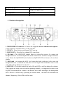
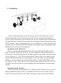
User Manual
CB Radio
PNI Escort HP 8000 ASQ
37
Before connecting and using this product, please read carrefully these instruction
manual and keep it for later use.
THERE ARE NO COMPONENTS THAT CAN BE REPAIRED BY THE USER.
FOR REPAIRS PLEASE REFER TO A N AUTHORIZED SERVICE.
ATENTION:
TO PREVENT FIRE HAZZARDS USE PROPER POWER SOURCE.
CONTENTS
1.
2.
3.
4.
5.
6.
Main Features............................................................................................................. 4
Technical Indicators .................................................................................................... 4
Product description ..................................................................................................... 5
Installation................................................................................................................... 7
Usefull tips .................................................................................................................. 8
Legal frequencies and transmiting powers in Europe: ............................................... 8
1. Main Features
• 40 AM/FM channels
• P/E Frequency band selectable (Russia and EU band switchable )
•
•
•
•
•
•
•
•
•
•
•
Mode AM/FM switch
RSSI indication (4 PCS LED indications)
2 Digit channel indicator
RF gain control
Volume with power ON/OFF control
TX/RX AS Q LED indicator
Up /Down microphone
Front microphone plug
Jack for external speaker
Manual Squelch
ANT Connector
2. Technical Indicators
Channels
Frequency range
Frequency control
Operating temperature
DC input voltage
Size
Weight
Receiver
IF
Sensitivity
Audio output
Audio distortion
Image rejection
Adjacent channel
Current drain
Transmitter
40 AM/FM
26.965 – 27.405 MHz
P.L.L.
-10° - +55°C
13.8Vdc ±15%
115 x 36 x 152 mm
0.8 kg
1° 10.7 MHz / 2° 450 KHz
-120dBm / 12dB SINAD (FM)
-107dBm / 12dB SINAD (AM)
@10% THD 2.5W la 8 ohm
<8% at 1 KHz
65 dB
85 dB
200 mA in stand-by
Maximum RF power
Modulation
ANT impedance
Current drain
4W FM la 13.8Vdc
85% la 90% (AM)
3KHz ±0.2 KHz (FM)
50 Ohm
2A
3. Product description
1. MICROPHONE connector : Connect the supplied electric condenser microphone
to this connector, and then lock it via the ring nut.
2. UP KEY : Press this key and channel NO. runs up.
3. DOWN KEY : Press this key channel NO. runs down.
4. SQ knob : The SQUELCH control allows to silent the receiver by cutting the
background noise. Turn the SQUELCH knob anticlockwise until the background noise
is cut. Rotate the SQUELCH knob clockwise (SQUELCH ON) to listen to the weakest
signals.
5. ASQ knob : to increase the ASQ level rotate the knob clockwise, in this case the
background noise is reduced but also the received signal. Recommended: turn on the
radio CB with the ASQ knob on the left.
6. OFF/VOL : This knob controls the radio ON and OFF as well as adjusts the volume.
If no signals are being received on the operating channel, it is suggested to turn on the
SQUELCH and adjust the volume to the desired level while listening to the background
noise. When it is turned on by operating the Volume knob,the radio will remember the
channel, frequency, AM or FM used last time.
7. AM/FM mode selector: This switch allows selecting the modulation mode AM/ FM.
8. Emergency channel or function mode selector: with this button you can select one
of the emergency channels 9/19 or the normal CH functioning mode. In the CH mode
you can select the number of the channel you want to use. In Romania they use channel
no22.
9. TX/ASQ LED: The indicator is bicolor light as red and green color. When TX
is red color, when ASQ on is green light.
10. RX Signal Meter: 4-bar RX signal Meter to monitor the strength of the received
signals.
11. DISPLAY: The digital LED display shows the channel.
A. Earphone and Microphone Jack
12. ANTENNA CONNECTOR
13. 13.8 VDC POWER CORD
14. EXT (External Speaker) Jack
15. PTT (Push-to-talk) key: Push the button to talk then release to receiving mode.
16. UP key 0f the microphone: This switch
allows increasing a channel number.
17. ASQ: Press this button, TX a nd ASQ
on the LED wo uld be green light, shows
ASQ turn on.
18. DN key of the microphone: This switch
allows decreasing a channel number.
19.
MICROPHONE
plug:
6-pole
microphone plug with locking ring nut, to be
connected to socket (1) located on the front
side of the radio.
4. Installation
Before installing the main unit in the vehicle, please check and select the most
convenient position, in order that the radio will be easy to reach and comfortable to
operate without disturbing or interfering driving. Use the supplied bracket and hardware
to install the radio. The bracket screws must be well tightened to avoid looseness as the
vehicle vibrates. The car mounting bracket can be installed over or below the radio and
the radio may be inclined as desired according to the specific type of installation (under
dashboard or track cabin roof installation).
Installation of the Main Unit
Before connecting the radio to the vehicle electric system, please make sure the
radio is powered off with the OFF/VOL (6) knob completely turned anticlockwise at
OFF position. The DC power cable of the radio includes a fuse holder with fuse located
on the red positive (+) wire. Please connect the DC power cable to the vehicle electric
system with special attention to correct polarity, even if the radio is protected against
polarity inversion. Connect the red wire to the positive (+) pole and the black wire to
the negative (-) pole of the vehicle electric system. Please make sure that the wires and
terminals are firmly connected, to prevent cables from disconnecting or causing short
circuits.
Installation of the Antenna
A specific mobile antenna adjusted for 27 MHz frequency range must be used. The
antenna installation must be done by a qualified technician or service center. Please
install the antenna carefully on the vehicle with proper connection to ground. Before
connecting the antenna to the radio, it is necessary to check the correct operation of the
antenna with low standing wave ratio (S.W.R.) via adequate instruments. If not, the
transmitter circuit of the radio could be damaged. The antenna usually must be installed
on the highest part of the vehicle, free from obstacles and as far away as possible from
any source of electric or electromagnetic noise. The RF antenna coaxial cable must not
be damaged or pressed on its way between antenna and the radio. The correct operation
of the antenna and the low standing wave ratio (S.W.R.) must be checked periodically.
Connect the RF antenna coaxial cable to the antenna connector (15), located on the rear
side of the radio.
Checking Operation of the Radio
Once radio has been connected to the vehicle electric system and to the antenna, the
correct operation of the system should be checked. Please proceed as following:
1) Check that the power cable is correctly connected.
2) Check that the RF antenna coaxial cable is properly connected.
3) Connect the microphone to the connector (1) that is on the front side of the radio.
4) Rotate the SQUELCH (4) knob anticlockwise.
5) Turn radio on by the OFF/VOL (6) knob and adjust volume to the desired level.
6) Select the desired channel with the up/down key on the front side of the radio.
7) Rotate the SQUELCH (4) knob clockwise to cut the background noise.
8) Press the PTT key to transmit and release it to receive.
9) Check the level of the received and transmitted signals on the 4 bar RX signal Meter
and TX LED. The transceiver will work correctly.
5. Useful tips
• Do not invert power polarity
• Do not replace the fuse with a bigger one. The default is 2A.
• Do not transmit without an antenna connected, you risc damaging the
device.
• Set the SQ and ASQ at the limit of the background noise.
6. Legal frequencies and transmitting powers in Europe:
Italy 40CH AM/FM 4 watt
Italy 34CH AM/FM 4 watt
Germany 80 CH FM 4watt/ 12 CH AM 1watt
Germany 40 CH FM 4watt/ 12 CH AM 1watt
Europe 40 CH FM 4 watt/ 40 CH AM 1watt
Romania CEPT 40 CH FM 4watt
Spain 40 CH AM/FM 4watt
France 40 CH FM 4watt/ 40 CH AM 1watt
GB 40 CH FM 4watt English frequencies + EC 40 CH FM 4 watt CEPT
frequencies
Specifications subject to change without notice!