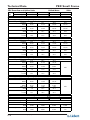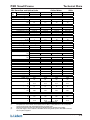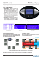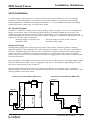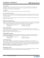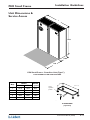
1
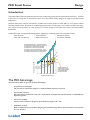
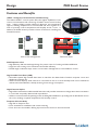
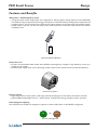
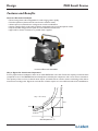
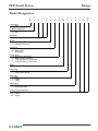
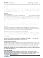
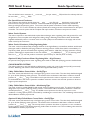
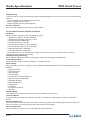
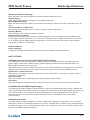
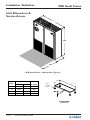
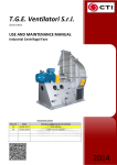
Contents
Design:
Introduction ............................................................. 1 - 1
Features and Benefits ........................................... 1 - 2
Model Designation ................................................ 1 - 5
Technical Data (50Hz):
Air/Water Cooled ................................................. 2 - 1
Chilled Water ......................................................... 2 - 3
iCOM Control System: .......................................... 3 - 1
Guide Specifications: .............................................. 4 - 1
Installation Guidelines: ......................................... 5 - 1
Unit Dimensions: ..................................................... 5 - 3
Technical Data Manual (08/08)
i
Design
PEX Small Frame
Introduction
The Liebert PEX is the next generation precision air conditioning system from Emerson Network Power. The PEX
is the latest in a long line of advanced products from the Liebert family designed to support business-critical
applications.
Sensitive electronics must be maintained in a stable environment of 20oC to 25oC (68oF to 77oF) with a relative
humidity of 40% to 55%. Precision air conditioning systems must not only keep room conditions within this range,
they must have the precision to react quickly to a drastic change in heat load and prevent wide temperature
fluctuations.
18
60
%
21
The ASHRAE document, "Thermal Guidelines
for Data Processing Environments", spells out
the temperature, dew point and humidity
specifications for electronic components
operating in mission-critical facilities. Types
of equipment typically found in these facilities
are enterprise servers and storage products.
24
27
Liebert PEX units are specifically developed for applications requiring close environmental control:
• Data Centres
• Telecom/CATV
• Computer Rooms
• Labs and Test Rooms
• Network Centres
• Production Facilities
%
15
50
Relative Humidity (%RH)
12
%
40
10
60%
50%
40%
10
Primary precision air
conditioning systems
keep room temperature
and humidity within
this area of control
12
15
18
21
24
27
Dry Bulb Temperature (oC)
The PEX Advantage
Only the Liebert PEX can give you all these advantages:
•
Comprehensive local support.
Full pre-sales and post-sales support is readily available, anytime you need it.
•
Customisation expertise.
PEX units can be customised to suit your requirements, with expertise and assistance from local R&D and
Engineering teams.
•
Full Service capability
Factory-trained Customer Engineers provide backup support 24 x 365.
•
Established company
Emerson Network Power has been designing and manufacturing precision environmental control systems
for over 30 years.
Technical Data Manual (08/08)
1-1
Design
PEX Small Frame
Features and Benefits
iCOM - Intelligent Communications and Monitoring
The Liebert iCOM™ control system offers the highest capabilities of unit
control, communication and monitoring of Liebert mission-critical cooling
units. Liebert iCOM provides advanced diagnostic and maintenance
support, enabling multiple units to communicate and work together as a
team to precisely control temperature and humidity across a room. In
addition, the iCOM network provides a choice of Teamwork, Lead/Lag and
Cascade functions.
Humidifier ON
Humidifier ON
Unit 1
Unit 2
Control Disables
Dehumidification
Unit 3
Power
Operating
Operating
Standby
Standby
UNBALANCED LOAD
Operating
Standby
Unit to Unit Configuration
Unit 6
Unit 5
Humidifier ON
NO LOAD
Unit 4
Teamwork Mode
SlabEvaporator Coils
• High efficiency slab heat exchanger design for precise control of cooling and dehumidification
• Large face area cooling coil to maximise heat transfer efficiency
• Double-angle condensate trays ensure correct water drainage and are removeable for service
High Sensible Heat Ratio (SHR)
• All models operate high sensible heat ratios to match the low latent loads of modern computer rooms and
telephone exchanges etc.
• With low latent capacity, little moisture is removed from the air so that humidity levels can be maintained
without extra humidification, thereby ensuring lower energy consumption
High/Constant Airflow
• High airflow achieves favourable sensible heat ratios and provides maximum air change rate to ensure variations
in room load are quickly detected and responded to
• Airflow is constant under all operating modes, including dehumidification, providing even air distribution across
the room resulting in optimal temperature and humidity control
Footprint & Serviceability
• High kW to footprint ratio
• Front accessible for installation and routine servicing
• Front doors are removeable, offering improved service access to the unit internals
1-2
Technical Data Manual (08/08)
Design
PEX Small Frame
Features and Benefits
DX Systems - Dehumidification Cycle
• Compressorised models employ split coil configurations, allowing latent cooling capacity to be substantially
increased but only as required so that energy consumption is minimised whilst providing close temperature and
humidity control. Room loads as low as 50% of unit cooling capacity can be supported with standard reheat.
• Smaller heater size and unit full load amps (FLA) lowers electrical connection requirements and reduces
installation costs
C
Split-Coil Dehumidification
Direct Drive Fan
• Forward curved double width double inlet (DWDI) centrifugal fans coupled to high efficiency motors are
standard on all models
• Insulated static regain ducts in floor discharge models reduce noise, turbulence and increase fan efficiency
Direct Drive System
Electric Heaters
• Single stage electric reheat system (2nd stage optional) employing low watt density, fin-tubular elements
• Optional Reheat/Humidifier lockout - reduces power requirements during emergency power operation
Dual Refrigerant Offering
All compressorised models are designed to operate on either HCFC R22 or HFC R407C refrigerants
R22
OR
R407C
Choice of Refrigerants
Technical Data Manual (08/08)
1-3
Design
PEX Small Frame
Features and Benefits
Immersed Electrode Humidifier
• Direct acting electrodes configurable for wide ranging water quality
• Fail safe operation (electrodes will not function without water)
• Water vapour introduced into coil bypass air avoids condensation
• Unique overflow flush cycle avoids problems associated with normal dump/drain valves
• Fully serviceable design ensures quick and cost effective maintenance
• Approved for direct connection to potable water supplies
Immersed Electrode Humidifier
Moisture, g/kg
Why is Bypass Air Introduction Important ?
From a psychrometric standpoint, return air at 24oC/45%RH has more than 5 times the capacity to absorb steam
compared to air at 14oC/80%RH that has already been cooled by the evaporator and is now close to saturation.
The capacity of this cool air to absorb water vapour is limited and can result in water condensing within the air
unit and surrounding areas. Bypass air introduction of water vapour is a more efficient method of humidification.
on
Li
ne
mbyp > 5 x mevap
i
at
ur %
t
S a 80
mevap
45 %
RH%
14
24
DB Temperature, oC
1-4
Technical Data Manual (08/08)
mbyp
Design
PEX Small Frame
Model Designation
1
2
3
4
5
6
7
8
9
10
11
12
13
14
15
P
1
0
1
5
F
A
P
M
L
1
S
0
0
0
Product Range
P = PEX
No. Modules - Bays/Fans
1 = One
2 = Two
Nominal kW
10 to 45
Air Path
F = Downflow (Forward Curve)
U = Upflow (Forward Curve)
Cooling Type
A = Air Cooled
W = Water Cooled
C = Chilled Water
Cooling Control
P = R-22, scroll, 1 compressor
Z = R-407C, scroll, 1 compressor
2 = 2 way CWV (CW, zero compressors)
3 = 3 way CWV (CW, zero compressors)
Voltage
M = 400/3/50
iCOM Display
S = Small Graphics Display
L = Large Graphics Display
Reheat Type
0 = None
1 = 1 Stage
2 = 2 Stage
Humidification
0 = None
S = Immersed Electrode
Factory Configuration Number
A-Z = Options
A-Z = Options
A-Z = Options
Technical Data Manual (08/08)
1-5
Technical Data
PEX Small Frame
PEX Downflow and Upflow Units
Model Size
Air/Water Cooled
1010
1015
2020
(1)
Rated Unit Performance R-22 and R-407C
24°C DB, 17.1°C WB (75.2°F DB, 62.8°F WB) 50% RH
Total kW
8.0
11.0
27,300
37,500
BTUH
Sensible kW
6.9
9.7
23,500
33,100
BTUH
24°C DB, 16.3°C WB (75.2°F DB, 61.3°F WB) 45% RH
Total kW
7.7
10.8
26,300
36,800
BTUH
Sensible kW
7.4
10.4
25,200
35,500
BTUH
24°C DB, 16.3°C WB (75.2°F DB, 61.3°F WB) 45% RH
Total kW
7.6
10.5
25,900
35,800
BTUH
Sensible kW
7.2
9.5
24,600
32,400
BTUH
2025
Downflow Units
16.7
21.0
57,000
71,700
14.5
20.6
49,500
70,300
16.0
21.3
54,600
72,700
15.3
21.1
52,200
72,000
(1)
Rated Unit Performance R-22 and R-407C
24°C DB, 17.1°C WB (75.2°F DB, 62.8°F WB) 50% RH
Total kW
7.9
10.8
27,000
36,800
BTUH
Sensible kW
6.7
8.9
22,900
30,400
BTUH
50Hz
Upflow Units
16.2
20.8
55,300
71,000
13.9
18.8
47,400
64,100
15.9
20.4
54,300
69,600
14.9
20.1
50,800
68,600
Evaporator Fan - Forward curve centrifugal fan, direct drive
10-10
Size
No. of fan assemblies
1
1
2
Downflow units
Static Regain duct
0.75 (1.0)
Std. Motor - kw (HP)
Downflow Airflow - l/s
940
1,070
1,880
2,000
2,270
3,990
CFM
Upflow Airflow - l/s
860
850
1,720
1,830
1,800
3,650
CFM
Evaporator Coil - Copper tubes with rifled bore tubes, louvred aluminium fins
No. of rows
2
3
2
Fin series - FPM
551
551
551
FPI
14
14
14
2
2,140
4,540
1,700
3,610
4
512
13
Compressor - Copeland Compliant Scroll with Crankcase Heater
No. of compressors
1
1
1
1
Unit cooling steps
2
2
2
2
LP cutout/in (auto reset) 140/420, HP cutout (manual reset) 2800
Safety controls - kPa
LP cutout/in (auto reset) 20/60, HP cutout (manual reset) 400
psig
Humidifier - Immersed Electrode, Cleanable
Capacity - kg/h
3.3
lb./hr
7
Input power - kW
2.5
3.3
7
2.5
Reheat - Single stage, low watt density, fin tubular electric elements
Capacity - kW
6
6
Opt. 2nd stage - kW
6
6
2-1
Technical Data Manual (08/08)
4.5
10
3.3
4.5
10
3.3
6
6
6
6
Technical Data
PEX Small Frame
PEX Downflow and Upflow Units
Model Size
1010
Air/Water Cooled
1015
2020
Filter - Dry media disposable G4 to AS/NZS1324.1 (MERV 8 to ASHRAE 52.2)
760x460x100 (30x18x4)
Downflow - mm (in)
Qty
1
1
2
650x590x75 (25.5x23x3)
Upflow - mm (in)
Qty
1
1
2
Full Load Current - 400 Volts, 3 phase+N+E, 50 Hz Supply
Standard Unit - Amps
20.6
22.0
50Hz
2025
2
2
(2)
26.3
26.3
(3)
Water Cooled Condenser - 316SS Brazed Plate Heat Exchanger - 2 Way
Valve Size
3/4"
3/4"
1"
0.42
0.59
0.90
Flow (4) - l/s
GPM
6.7
9.4
14.3
Water
PD - kPa
16
14
22
ft. H2O
5.4
4.7
7.4
1"
1.11
17.6
28
9.4
Unit Connections
Hot Gas - O.D.
Qty
A
Liquid - O.D.
Qty
Supply - I.D.
Qty
W
Return - O.D.
Qty
IE Hum. Drain - O.D.
Hum. Supply - BSP
1/2"
1
1/2"
1
7/8"
1
7/8"
1
25
1/2"
5/8"
1
1/2"
1
7/8"
1
7/8"
1
25
1/2"
3/4"
1
1/2"
1
1-1/8"
1
1-1/8"
1
25
1/2"
3/4"
1
1/2"
1
1-1/8"
1
1-1/8"
1
25
1/2"
Unit Dimensions & Weight
Width - mm
in.
Depth - mm
in.
Height - mm
in.
Weight - kg
lbs
832
33
550
21.7
1950
77
170
374
832
33
550
21.7
1950
77
180
396
1662
65
550
21.7
1950
77
260
572
1662
65
550
21.7
1950
77
270
594
0.46
4.9
1.16
12.5
0.46
0.91
4.9
9.8
1.16
2.33
12.5
25.0
850 (33.5) front only
0.91
9.8
2.33
25.0
Unit Footprint
Unit only - m2
ft2
Incl. Service area - m2
ft2
Serv. Access - mm (in)
NOTES:
(1)
All capacities are nominal values. Gross capacity based on 25Pa (0.1" H2O) ESP, 0m a.s.l. For net capacities,
deduct fan input power. Refer Liebert Rating Program for specific input conditions.
(2)
Input power supply +/-15%. FLA excludes heat rejection equipment. Refer IOM for electrical data on optional
equipment.
Standard pressure water regulating valve (WRV) 1,000 kPa. Optional 2 way high pressure WRV (2,400 kPa)
available.
(3)
(4)
Nominal flow & pressure drop figures are for total unit. Based upon 24°CDB/50%RH, 30°C EWT & 35.5°C LWT,
R22 refrigerant
Technical Data Manual (08/08)
2-2
Technical Data
PEX Small Frame
PEX Downflow and Upflow Units
Model
Size
Downflow
Upflow
1015
1015
Chilled Water
2020
2020
2030
2030
(1)
Rated Unit Performance
24°C DB, 17.1°C WB (75.2°F DB, 62.8°F WB) 50% RH
Based on 7oC (44.6oF) EWT, 12.5oC (54.5oF) LWT
Total kW
13.2
27.1
45,000
92,500
BTUH
Sensible kW
12.1
22.5
41,300
76,800
BTUH
Flow - l/s
0.57
1.18
GPM
9.0
18.7
Pressure Drop - kPa
49
124
ft. H2O
16.4
41.5
24°C DB, 16.3°C WB (75.2°F DB, 61.3°F WB) 45% RH
Based on 7oC (44.6oF) EWT, 12.5oC (54.5oF) LWT
Total kW
12.3
23.9
42,000
81,500
BTUH
Sensible kW
12.3
23.0
42,000
78,500
BTUH
Flow - l/s
0.53
1.04
GPM
8.4
16.5
Pressure Drop - kPa
43
97
ft. H2O
14.4
32.5
24°C DB, 17.1°C WB (75.2°F DB, 62.8°F WB) 50% RH
Based on 7oC (44.6oF) EWT, 12.5oC (54.5oF) LWT
Total kW
11.3
25.7
38,600
87,700
BTUH
Sensible kW
9.8
21.2
33,400
72,300
BTUH
Flow - l/s
0.50
1.12
GPM
7.9
17.8
Pressure Drop - kPa
38
112
ft. H2O
12.7
37.5
24°C DB, 16.3°C WB (75.2°F DB, 61.3°F WB) 45% RH
Based on 7oC (44.6oF) EWT, 12.5oC (54.5oF) LWT
Total kW
10.4
22.8
35,500
77,800
BTUH
Sensible kW
10.3
21.6
35,100
73,700
BTUH
Flow - l/s
0.50
0.99
GPM
7.9
15.7
Pressure Drop - kPa
38
90
ft. H2O
12.7
30.2
50Hz
2040
N/A
Downflow Units
36.8
48.4
125,600
165,100
30.4
36.6
103,700
124,900
1.60
25.4
122
40.9
2.10
33.3
167
55.9
32.7
43.1
111,600
147,100
31.0
37.1
105,800
126,600
1.42
22.5
97
32.5
1.87
29.6
133
44.6
Upflow Units
34.6
118,100
28.2
96,200
1.50
23.8
108
36.2
n/a
30.8
105,100
28.7
97,900
1.34
21.2
87
29.1
n/a
Evaporator Fan - Forward curve centrifugal fan, induction motor, self-tensioning belt drive
10-10
Size
No. of fan assemblies
1
2
2
2
Downflow units
Static Regain duct
0.75 (1.0)
Std. Motor - kw (HP)
Downflow Airflow - l/s
1,175
1,880
2,350
2,350
CFM
2,490
3,990
4,990
4,990
Upflow Airflow - l/s
860
1,720
2,120
n/a
CFM
1,830
3,650
4,500
n/a
2-3
Technical Data Manual (08/08)
Technical Data
PEX Small Frame
PEX Downflow and Upflow Units
Downflow
Upflow
Model
Size
1015
1015
Chilled Water
2020
2020
50Hz
2030
2030
2040
N/A
4
512
13
5
512
13
On/Off
25 (1)
3.0 (3.5)
172 (25)
On/Off
25 (1)
3.0 (3.5)
173 (25)
Modulating
32 (1-1/4)
10 (11.6)
590 (86)
4.5
10
3.3
4.5
10
3.3
4.5
10
3.3
9
9
9
9
Evaporator Coil - Copper tubes, louvred aluminium fins
No. of rows
3
3
Fin series - FPM
551
551
FPI
14
14
(2)
Chilled Water Valve - 2 Way Valve
Action
On/Off
Size - mm (in.)
19 (3/4)
Control Port, Kv (Cv)
2.2 (2.5)
Close Off - kPa (psig)
276 (40)
Humidifier - Immersed Electrode, Cleanable
Capacity - kg/h
3.3
lb./hr
7
Input power - kW
2.5
Reheat - Single stage, low watt density, fin tubular electric elements
Capacity - kW
6
6
Opt. 2nd stage - kW
6
6
Filter - Dry media disposable G4 to AS/NZS1324.1 (MERV 8 to ASHRAE 52.2)
760x460x100 (30x18x4)
Downflow - mm (in)
Qty
1
2
2
650x590x75 (25.5x23x3)
Upflow - mm (in)
Qty
1
2
2
Full Load Current - 400 Volts, 3 phase+N+E, 50 Hz Supply
Standard Unit - Amps
15.6
16.3
2
n/a
(3)
19.8
19.8
Unit Connections
Supply
Return
IE Hum. Drain - O.D.
IR Hum. Drain - FPT
Hum. Supply - BSP
Unit Dimensions & Weight
Width - mm
in.
Depth - mm
in.
Height - mm
in.
Weight - kg
lbs
3/4" BSP
3/4" O.D.
25mm
3/4"
1/2"
1" BSP
1" O.D.
25mm
3/4"
1/2"
1" BSP
1" O.D.
25mm
3/4"
1/2"
1-3/8" O.D.
1-3/8" O.D.
25mm
3/4"
1/2"
832
33
550
21.7
1950
77
130
286
1662
65
550
21.7
1950
77
200
440
1662
65
550
21.7
1950
77
200
440
1662
65
550
21.7
1950
77
230
506
0.46
4.9
1.16
12.5
0.91
0.91
9.8
9.8
2.33
2.33
25.0
25.0
850 (33.5) front only
0.91
9.8
2.33
25.0
Unit Footprint
Unit only - m2
ft2
Incl. Service area - m2
ft2
Serv. Access - mm (in)
NOTES:
(1)
(2)
(3)
All capacities are nominal values. Gross capacity based on 25Pa (0.1" H2O) ESP, 0m a.s.l. For net capacities,
deduct fan input power. Refer Liebert Rating Program for specific input
Standard pressure chilled water valve body rating 2,068 kPa (300 psig). Optional 3 way available.
Input power supply +/-15%. FLA based on humidifier lockout during reheat operation. Refer IOM for electrical
data on optional equipment.
Technical Data Manual (08/08)
2-4
Technical Data
PEX Small Frame
This page intentionally left blank
2-5
Technical Data Manual (08/08)
PEX Small Frame
iCOM Control
The Liebert iCOM control system featured on the Liebert
PEX brings high-level supervision to multiple units allowing
them to work together as a single system to optimise room
performance. The Liebert iCOM control system offers a
variety of advantages.
The standard Small Graphic Display features a 128x64 dot matrix backlit
screen. Advanced monitoring can be achieved with the addition of the Optional
Wall Mounted Display.
Intelligent Communications and Monitoring
•
•
•
•
Saves Energy using Predictive Humidity Control
Built-in Lead/Lag Functions for enhanced system reliability
Wellness Calculation alerts service personnel before problems occur
Unit to Unit (U2U) Communications allows Lead/Lag and optional
teamwork settings for maximum flexibility and control
• Optional IntelliSlot cards offer external monitoring through Modbus
RTU and HTTP/SNMP protocols
The optional Wall Mounted
Large Graphic Display provides
centralised monitoring and
control of connected Liebert
PEX units.
The Liebert IntelliSlot Web
and 485 cards can provide
Liebert SiteScan® Web and
BMS systems with the
capability to monitor your
Liebert PEX unit.
Technical Data Manual (08/08)
3-1
iCOM Control
PEX Small Frame
Additional Views Available with
Large Graphic Displays
• System View - Allows you to see the
average operation of the "system" or all
units that are working together in Unit to
Unit (U2U) Communications mode for
Teamwork or Lead/Lag from a centralised
location.
• Spare Parts List - Critical spare part
numbers are saved in unit memory and may
be displayed on the Large Graphic Display,
speeding identification of parts.
• Unit Diary - Free field area within the unit
memory where unit maintenance shares
history with any authorised users, including
record of what others have done.
View Network
The optional Large Graphic Display features a 320x240 dot
matrix backlit screen with helpful system and maintenance views.
Spare Parts
U2U Configuration Example
Liebert PEX units with Small Graphic Display may be
centrally monitored and controlled with the Optional
Wall Mounted Large Graphic Display.
Unit Diary
Teamwork: Mode 2
Units work together to provide precision cooling in
rooms with unbalanced loads.
Humidifier ON
Humidifier ON
Unit 1
Unit 2
Control Disables
Dehumidification
Unit 3
Power
Operating
Operating
UNBALANCED LOAD
Standby
Standby
Unit 6
Operating
Standby
Unit 5
Humidifier ON
(Note: Field supplied network switch required for unit-to-unit communications)
Refer 051536 iCOM User manual for further information on iCOM features and operation.
3-2
NO LOAD
Technical Data Manual (08/08)
Unit 4
PEX Small Frame
Guide Specifications
GENERAL
Summary
These specifications describe requirements for a Mission Critical Cooling system. The system shall be designed
to control temperature and humidity conditions in rooms containing electronic equipment, with good
insulation and vapour barrier. The manufacturer shall design and furnish all equipment to be fully compatible
with heat dissipation requirements of the room.
PRODUCT
Design Requirements
The Mission Critical Cooling system shall be a Liebert PEX model ________ self-contained factory assembled
unit with (upflow) (downflow) air delivery. The system shall have a total cooling capacity of ______ kW, with a
sensible cooling capacity of ______ kW, based on an entering air temperature of ____ °C dry bulb and ____
°C wet bulb. The unit is to be supplied with ____ volt ___ ph ___Hz electrical service and include a rating
nameplate stating the unit FLA or kW/kVA.
Cabinet Construction
The frame shall be constructed of 2.5, 2.0 and 1.2 mm folded galvanised steel. The exterior panels shall be
constructed of 1.2 mm zinc coated sheet steel and insulated with foam insulation. The cabinet shall be powder
coated in Charcoal Grey colour and have a textured finish. The front panels shall be removeable and include
captive 1/4 turn fasteners. The cabinet shall be assembled with pop rivets providing ease of disassembly.
Filtration
The filter panels shall be an integral part of the system and withdrawable from the top (downflow)/front
(upflow) of the unit. Filtration shall be provided by deep V form, dry disposable media housed in a metal frame.
The rated efficiency shall be G4 to AS/NZS 1324.1 (MERV8 to ASHRAE 52.2 Standard).
Standard FC Fans - Direct Expansion and Chilled Water Systems
The fan section shall be designed for ______ l/s at an external static pressure of ____ Pa. The unit shall be
fitted with one (two) direct drive, forward curved (FC) centrifugal type, double width, double inlet fan(s). Each
fan shall be separately driven by a multi-speed high efficiency electric motor. They shall be statically and
dynamically balanced.
HUMIDIFIER
A humidifier shall be factory installed inside the unit. Bypass air shall be used to enable moisture to be
absorbed into the airstream without condensation. The humidifier capacity shall be ____ kg/hr (lb/hr). The
humidifier shall be serviceable and removable from the front of the unit.
Immersed Electrode Humidifier
Humidification shall be provided by boiling water in a high temperature polypropylene steam generator. The
humidifier shall have an efficiency of not less than 1.3 kg/kW and be fitted with an auto flush cycle activated on
demand from the microprocessor control system. The humidifier shall be fully serviceable with replaceable
electrodes. Waste water shall be flushed from the humidifier by the initiation of the water supply solenoid
water valve via a U-pipe overflow system. Drain solenoid valves will not be used. The humidifier shall be
approved for direct connection to potable water supplies in accordance with ATS 5200.101 and carry the
WaterMark label. Humidifier steam nozzles shall be readily accessible for inspection and cleaning in accordance
with AS/NZS 3666.2.2002 Cl 2.3.3.1.
ELECTRIC HEATING
Electric heating shall be provided in a single stage. The elements shall be of low watt density and high
temperature painted steel fin tubular construction, protected by thermal safety switches. The heating system
shall include dual safety protection through loss of air and manual reset high temperature controls in
accordance with AS/NZS 3102.2002 Cl 7.3.
Technical Data Manual (08/08)
4-1
Guide Specifications
PEX Small Frame
Optional 2nd Stage Electric Heating
Electric heating shall be provided in two equal stages. The elements shall be of low watt density and high
temperature painted steel fin tubular construction, protected by thermal safety switches. The heating system
shall include dual safety protection through loss of air and manual reset high temperature controls in
accordance with AS/NZS 3102.2002 Cl 7.3.
COMPRESSORISED SYSTEMS
Scroll Compressor
The compressor shall be of the high efficiency Compliant Scroll design, with an E.E.R. (energy efficiency ratio)
of not less than 11.1 BTUH/watt (C.O.P. of not less than 3.25) at ARI rating conditions. The compressor shall
be charged with polyolester oil and designed for operation on HCFC R22 or HFC R407C. Each compressor
shall have internal motor protection and be mounted on vibration isolators.
Refrigeration Circuit
The refrigeration system shall be of the direct expansion type with two cooling stages and incorporate one
hermetic scroll compressor, complete with crankcase heater. A hot gas bypass solenoid valve shall be used to
provide 50% or 100% cooling capacity. The system shall include a manual reset high pressure control, auto
reset low pressure switch, externally equalised thermal expansion valve, high sensitivity refrigerant sight glass,
large capacity filter drier and charging/access ports in each circuit.
Evaporator Coil
The coil shall be constructed of enhanced surface aluminium fins mechanically bonded to copper tubes, with
the frame and drip tray fabricated from heavy gauge aluminium. All metal parts in contact with condensate shall
be the same material to prevent electrolytic corrosion. The evaporator drain tray shall incorporate double
sloped gutters for complete condensate removal and shall be removeable for cleaning in accordance with AS/
NZS 3666.1.2002 Cl 2.8.1. The cooling coil shall be a maximum of 5 rows and 551 fins per metre (14 FPI) and
the face velocity shall not be more than 2.5 m/s (500 fpm).
Dehumidification
A specific dehumidification cycle (split-suction) shall operate by reducing the operating surface temperature in
a section of the refrigeration coil by means of a solenoid valve on the suction header. Room loads as low as
50% of the unit sensible cooling capacity shall be supported during dehumidification without the need for
larger capacity or additional heating stages. Full airflow of the unit will be maintained at all times to ensure
consistent air distribution to the conditioned space.
Air Cooled Systems
The indoor evaporator unit shall include refrigerant piping, with a factory holding charge of nitrogen. The
refrigeration circuit shall include rigidly mounted isolation valves in the discharge and liquid lines to aid
servicing and installation.
Remote Air Cooled Condenser
The model ________ air cooled condenser shall be the low profile, weatherproof type incorporating high
efficiency, direct drive, external rotor motors with axial blade fans. The condenser shall balance the heat
rejection of the compressor at ___°C ambient. The condenser shall be constructed from heavy duty
aluminium and corrosion resistant components. Heavy duty mounting legs and all assembly hardware shall be
included. Condensers shall be suitable for 24 hour operation and be capable of providing vertical or horizontal
discharge. The condenser shall be fully factory wired to an input isolator and require 230 volt 1 phase ___Hz
electrical service. The high performance heat exchanger shall include mechanically expanded cross-hatched
copper tubes and louvred aluminium fins for maximum heat transfer. The coil shall be finished in a high
performance modified epoxy coating (KoilKote®) to offer increased protection in aggressive environments.
4-2
Technical Data Manual (08/08)
PEX Small Frame
Guide Specifications
The coil shall be have a maximum of __ rows and ____ fins per metre (__ FPI) and the face velocity shall not
be more than ___ m/s (___ FPM).
Fan Speed Control Condenser
The condenser fans shall be directly driven by __ pole ____ rpm 230 volt ___ Hz electric motors with an
IP54 enclosure rating and class F insulation. The motors shall be equipped with permanently sealed ball
bearings and high temperature grease. The motors shall be speed controlled to ensure stable operating
conditions from -5°C to 45°C ambient by a factory fitted, direct acting pressure actuated electronic fan speed
controller. The control system shall be complete with input isolator, transducers and pressure switch.
Water Cooled Systems
The indoor evaporator unit shall include a plate heat exchanger, water regulating valve and pipework for each
refrigeration circuit, complete with refrigerant holding charge. Balancing and isolation valves shall be field
supplied and fitted by others. A strainer with 1mm mesh (#20) must be installed on the supply side of each
water circuit by the contractor.
Water Cooled Condenser, 2 Way Regulating Valve
The water cooled condenser/heat exchanger shall be of the high efficiency, counterflow, stainless steel brazed
plate type rated for 3000 kPa (435 psig) maximum working pressure. Water flow shall be controlled by a 2way factory fitted, pressure actuated water regulating valve rated for 1000 kPa (145 psig) maximum working
pressure. Water/glycol requirements for the unit shall be ____ l/s (USGPM) of ____°C (°F) entering water
based on a ___ K (°F) rise and produce a maximum pressure drop of 150 kPa (50 ft. of water).
Optional 2 Way Condenser Water Regulating Valve - High Pressure
An optional 2 way high pressure water regulating valve rated for 2400 kPa (350 psig) pressure shall be fitted.
CHILLED WATER SYSTEMS
The indoor evaporator unit shall include a chilled water cooling coil, control valve and (on/off) (motorised)
actuator. Balancing and isolation valves shall be field supplied and fitted by others.
2 Way Chilled Water Control Valve - On/Off Type
The water circuit shall include 2-way on/off type spring return control valve. The valve body shall be designed
for up to 20 bar (300 psig) water pressure. The actuator/valve combination shall have a maximum closeoff
pressure of ___ bar (___ psig). The iCOM control opens/closes the valve in response to room conditions.
For dehumidification, the valve is opened to establish maximum moisture removal and operate its reheat to
support space temperature.
2 Way Chilled Water Control Valve - Modulating Type
The water circuit for model P2040FC shall include 2-way modulating control valve. The valve body shall be
designed for up to 20 bar (300 psig) water pressure. The actuator/valve combination shall have a maximum
closeoff pressure of ___ bar (___ psig). The iCOM control positions the valve in response to room
conditions. Cooling capacity will be controlled by modulating the control valve. The modulating valve travel for
dehumidification shall be proportional.
Optional 3 Way Chilled Water Control Valve - On/Off Type
The water circuit shall include 3-way on/off type spring return control valve. The valve body shall be designed
for up to 20 bar (300 psig) water pressure. The actuator/valve combination shall have a maximum closeoff
pressure of ____ bar (____ psig). The microprocessor positions the valves in response to room conditions.
Cooling capacity will be controlled by bypassing chilled water around the coil. The modulating valve travel for
dehumidification shall be proportional.
Technical Data Manual (08/08)
4-3
Guide Specifications
PEX Small Frame
Optional 3 Way Chilled Water Control Valve - Modulating Type
The water circuit for model P2040FC shall include 3-way modulating control valve. The valve body shall be
designed for up to 20 bar (300 psig) water pressure. The actuator/valve combination shall have a maximum
closeoff pressure of ____ bar (____ psig). The microprocessor positions the valves in response to room
conditions. Cooling capacity will be controlled by bypassing chilled water around the coil. The modulating
valve travel for dehumidification shall be proportional.
UNIT SIZE
Compressorised Systems
The maximum footprint area of the unit shall not exceed:
0.46 m2 up to 11 kW
0.92 m2 above 11 and up to 21 kW
The unit shall require front access only for routine service and installation work.
Chilled Water Systems
The maximum footprint area of the unit shall not exceed:
0.46 m2 up to 13 kW
0.92 m2 above 13 and up to 48 kW
The unit shall require front access only for routine service and installation work.
4-4
Technical Data Manual (08/08)
PEX Small Frame
Guide Specifications
ALL SYSTEMS
Water Under Floor Sensor (LWD)
Each unit shall be supplied with a single water under floor point detector as standard. Up to 5 sensors in total
may be connected in series from each iCOM cooling unit. Any individual sensor shall signal a water under floor
alarm to the controller upon detecting water.
iCOM Microprocessor Control with SMALL Graphic Display
The iCOM unit control shall be factory-set for Intelligent Control which uses "fuzzy logic" and "expert
systems" methods. Proportional and Tunable PID shall also be user selectable options. Internal unit component
control shall include the following:
Compressor Short Cycle Control
Prevents compressor short-cycling and needless compressor wear
System Auto Restart
The auto restart feature will automatically restart the system after a power failure. Time delay is
programmable
Sequential Load Activation
On initial startup or restart after power failure, each operational load is sequenced with a minimum of
one second delay to minimize total inrush current
Predictive Humidity Control
Calculates the moisture content in the room and prevents unnecessary humidification and
dehumidification cycles by responding to changes in dew point temperature
The iCOM control shall be compatible with all Liebert remote monitoring and control devices. Options are
available for BMS interface via MODbus, BACNet and SNMP.
The iCOM control processor shall be microprocessor based with a 128x64 dot matrix graphic front monitor
display and control keys for user inputs mounted in an ergonomic, aesthetically pleasing housing. The controls
shall be menu driven. The display & housing shall be viewable while the unit panels are open or closed.
The display shall be organized into three main sections: User Menus, Service Menus and Advanced Menus.
The system shall display user menus for: active alarms, event log, graphic data, unit view/status overview
(including the monitoring of room conditions, operational status in % of each function, date and time), total run
hours, various sensors, display setup and service contacts. A password shall be required to make system
changes within the service menus. Service menus shall include: setpoints, standby settings (lead/lag), timers/
sleep mode, alarm setup, sensor calibration, maintenance/wellness settings, options setup, system/network
setup, auxiliary boards and diagnostics/service mode. A password shall be required to access the advanced
menus.
User Menus Shall be Defined as Follows:
Active Alarms
Unit memory shall hold the 200 most recent alarms with time and date stamp for each alarm
Event Log
Unit memory shall hold the 400 most recent events with id number, time and date stamp for each event
Graphic Data View
Two graphic records shall be available: return air temperature and return air humidity
Unit View - Status Overview
Simple or Graphical. Unit View summary displays shall include temperature and humidity values, active
functions (and percent of operation) and any alarms of the host unit.
Total Run Hours
Menu shall display accumulative component operating hours for major components including compressors, fan
motor, humidifier and reheat
Technical Data Manual (08/08)
4-5
Guide Specifications
PEX Small Frame
Display Setup
Customer shall pre-select the desired grouping of display languages at the time of the order from the following
choices:
Group 1: English, French, Italian, Spanish, German
Group 2: English, Russian, Greek
Group 3: English, Japanese, Chinese, Arabic
Service Contacts
Menu shall allow display of local service contact details.
Service Menus Shall be Defined as Follows:
Setpoints
Menu shall allow setpoints within the following ranges:
• Temperature Setpoint 18-29ºC (65-85ºF)*
• Temperature Sensitivity 0.6-5.6ºC (1-10ºF)
• Humidity Setpoint 20-80% RH*
• Humidity Sensitivity 1-30% RH
• High Temperature Alarm 2-32ºC (35-90ºF)
• Low Temperature Alarm 2-32ºC (35-90ºF)
• High Humidity Alarm 15-85% RH
• Low Humidity Alarm 15-85% RH
* The microprocessor may be set within these ranges, however the unit may not be able to control to extreme
combinations of temperature and humidity.
Standby Settings/Lead-Lag
Menu shall allow planned rotation or emergency rotation of operating and standby units.
Timers/Sleep Mode
Menu shall allow various customer settings for turning on/off unit.
Alarm Setup
Menu shall allow customer settings for alarm notification (audible/local/remote). The following alarms shall be
available:
• High Temperature
• Low Temperature
• High Humidity
• Low Humidity
• Compressor Overload (Optional)
• Main Fan Overload (Optional)
• Humidifier Problem
• High Head Pressure
• Change Filter
• Fan Failure
• Low Suction Pressure
• Unit Off
Audible Alarm
The audible alarm shall annunciate any alarm that is enabled by the operator.
Common Alarm
A programmable common alarm shall be provided to interface user selected alarms with a remote alarm
device.
Remote Monitoring
All alarms shall be communicated to the Liebert monitoring system with the following information: Date and
time of occurrence, unit number and present temperature and humidity.
Sensor Calibration
Menu shall allow unit sensors to be calibrated with external sensors.
4-6
Technical Data Manual (08/08)
PEX Small Frame
Guide Specifications
Maintenance/Wellness Settings
Menu shall allow reporting of potential component problems before they occur.
Options Setup
Menu shall provide operation settings for the installed components.
System/Network Setup
Menu shall allow Unit-to-Unit (U2U) communication and setup for teamwork modes of operation (up to 32
units).
Teamwork Modes of Operation
Saves energy by preventing operation of units in opposite modes multiple units.
Auxiliary Boards
Menu shall allow setup of optional expansion boards.
Diagnostics/Service Mode
Control input and output values and status shall be displayed to aid in unit diagnostics and troubleshooting.
Control inputs shall be indicated as on or off at the front display. Control outputs shall be able to be turned
on or off from the front display without using jumpers or a service terminal. Each control output shall be
indicated by an LED on a circuit board.
Advanced Menus
Factory Settings
Configuration settings shall be factory-set based on the pre-defined component operation.
UNIT OPTIONS
iCOM Microprocessor Control With LARGE Graphic Display
The iCOM unit control with large graphic display shall include all of the features as the iCOM with small
graphic display, except that it includes a larger graphical display and shall include the additional features of:
"System View", Spare Parts List, Unit Diary.
The iCOM control processor shall be microprocessor based with a 320x240 dot matrix graphic front monitor
display panel and control keys for user inputs mounted in an ergonomic, aesthetically pleasing housing.
System View - Status Overview
"System View" shall display a summary of operation for the total number of operating units within a Unit-toUnit(U2U) configuration.
Spare Parts List
Menu shall include a list of critical spare parts, their quantity and part numbers.
Unit Diary
Menu shall include a free field area within the unit memory where unit history may be stored for reference.
iCOM Wall Mount LARGE Graphic Display
The iCOM Large Graphic Display Kit shall include an ergonomic, aesthetically pleasing housing, a 320x240 dot
matrix graphic display and a 230V (120V) power supply. The Wall Mount Large Graphic Display shall be used to
allow remote location of a "System View" display and all features of the Large Graphic User, Service and
Advanced menus for use with Liebert iCOM controlled products connected for Unit-to-Unit (U2U)
communications.
vNSA Network Switch
The vNSA network switch is designed to connect multiple iCOM equipped cooling units to form a network
and allow the units to communicate and function as a team. Available with or without a Large Graphics Display,
the vNSA can support up to 14 Small Graphics Display units. Supplied in a wall mount enclosure with key lock.
Requires 100-240VAC single phase power.
Technical Data Manual (08/08)
4-7
Guide Specifications
PEX Small Frame
IntelliSlot WEB Card
The Liebert IntelliSlot Web card provides HTTP browsing, SNMP and WEB-management capability of Liebert
PEX units within your Network Management System (NMS).
IntelliSlot 485 Card
The Liebert IntelliSlot 485 card provides BMS management of Liebert PEX units over EIA-485 via Modbus RTU
or Liebert’s proprietary protocol for SiteLink connectivity.
iCOM Ethernet Cable
Certified CAT5e patch cable with fully moulded ends used for connecting an iCOM to a network switch.
Available in lengths of 10, 15, 20, 30 and 45 metres (33, 50, 65, 100 and 150 feet). Bulk cable is also available in
305 metre (1000 feet) rolls.
iCOM Ethernet Crossover Cable
Certified CAT5e crossover cable with fully moulded ends for networking 2 Small Graphics Display iCOM units
together are available in lengths of 10, 20 and 30 metres (33, 65 &100 feet).
Remote Air Cooled Condenser Power Kit
A 10 amp rated single pole circuit breaker and contactor shall be provided in the electrical panel for field
connection to power the remote factory matched air cooled condensers.
Long Line Pipe Kit - Air Cooled Systems
A factory fitted liquid line solenoid valve and field installed non-return valve (supplied loose) shall be provided
for the refrigeration circuit to prevent liquid refrigerant migration to the evaporator/compressor during off
cycles in air cooled installations. Note: Mandatory for pipe runs in excess of 30 metres.
Condensate Pump - Immersed Electrode Humidifier equipped units
The condensate pump shall have a nominal capacity of 1625 l/hr (430 USGPH) at 3.2 m (10 ft.) head and be
suitable for pumping 100oC (212oF) water. It shall be complete with integral dual-float switches, pump-andmotor assembly and reservoir. The secondary float shall send a signal to the local alarm and shut down the
unit upon high water condition. The pump shall be supplied loose and be field installed external to the unit.
Reheat/Humidifier Lockout (Emergency Power Lockout)
A field supplied 24VAC source to field wiring terminals in the electrical panel will lockout the electric heaters
and humidifier.
Common Alarm Terminals (Additional)
A total of three (3) common alarm terminals (normally open) rated at 24VAC 3 amps each shall provide
remote alarm indication.
Phase Fault Relay
The unit shall shutdown upon detection of a loss of any phase and report an alarm.
Main Fan Auxiliary Contact
Dry contact terminals (normally open) shall provide remote status indication for the main fan(s).
Water Under Floor Sensor (LWD)
Additional water under floor sensors (up to 5 in total) may be series connected under the raised floor. Note:
each unit is shipped with one (1) off LWD sensor and 3.7m (12 feet) lead as standard.
4-8
Technical Data Manual (08/08)
PEX Small Frame
Guide Specifications
Liquitect Unit Shutdown Sensor (LT410)
Liquitect signal shuts down unit, and provides one (1) N/O contact for field alarm connection.
Low Pressure Transducer
Replaces the standard pressure switch to indicate refrigerant suction pressure via the iCOM display panel.
Remote Sensors
Remote temperature and humidity sensor compatible with iCOM controls are available in lengths of 9, 18, 27,
36 and 45 metres (30, 60, 90, 120 and 150 feet).
Floor Stand
The floor stand shall be constructed from welded galvanised steel. The floor stand shall have adjustable legs
and be _____ mm (in.) high.
Upflow Unit Plenum with Discharge Grille(s)
The air plenum shall be constructed from 1.2mm zinc coated sheet steel and powder coated in Charcoal Grey
colour with a textured finish. The plenum shall be 400 mm (15.75 in.) high. Double deflection discharge grilles
made from aluminium and powder coated black shall be fitted to the front panels.
Technical Data Manual (08/08)
4-9
Guide Specifications
PEX Small Frame
This page intentionally left blank
4 - 10
Technical Data Manual (08/08)
Installation Guidelines
PEX Small Frame
Unit Installation
To achieve design performance and maximum product life, correct installation is vital. The following
information relates specifically to our products and should be applied in conjunction with prevailing
industry standards for mechanical and electrical installations. For more detailed information on installing
Liebert PEX systems, please refer to the PEX User manual.
Air Cooled Systems
The PEX air cooled unit is shipped with a factory holding charge of nitrogen. Each circuit is supplied with
quarter turn isolation valves on the liquid and discharge lines to facilitate installation and servicing. The
refrigerant piping must be connected in the field to a matched air cooled condenser and then pressure
tested, dehydrated and charged with either R22 or R407C refrigerant. In addition the following services are
required to make the system operational:
• electrical supply to the indoor unit
• electrical supply to the air cooled condenser
• humidifier drain
• humidifier water supply
Refrigeration Piping
All refrigeration piping joints must be high temperature silver brazed. Avoid using solders containing
hazardous substances. Any applicable local codes relating to fire safety in terms of pressure relief must be
observed. Standard industry procedures must be followed for selection and placement of pipe supports,
system evacuation, oil addition and charging with refrigerant. Consideration must be given to pipeline
pressure drop, oil return to the compressor, avoidance of oil logging in parts of the system and minimisation
of noise and vibration.
Pipe sizing tables are provided in 051539 User manual for each model and are for 'equivalent lengths', which
include an allowance for bends. They are suggestions only and it is the installer’s responsibility to confirm
that sizes are appropriate for site conditions.
Note: An optional long-line pipe kit, comprising a liquid line shutoff valve and non-return valve*, is required for
equivalent lengths in excess of 30 metres. Consult the factory whenever the equivalent length exceeds 60m, or if the
vertical separations exceed those shown.
Condenser Located Above PEX Unit:
PEX unit
5m max.
discharge
liquid
20m max.
7.5m max.
trap
liquid
discharge
*
PEX unit
Condenser Located Below PEX Unit:
*
Technical Data Manual (08/08)
5-1
Installation Guidelines
PEX Small Frame
• Discharge line
Discharge lines should be insulated where they are routed in the conditioned space (including under a
raised floor). Traps must be fitted in vertical risers every 7.5 metres and at the base of a riser. Slope
discharge lines in the direction of refrigerant flow.
• Liquid line
Liquid lines should not be exposed to any heat sources and should be insulated.
Air cooled condenser location
Condensers should be located for maximum security and maintenance accessibility. Vertical or horizontal
discharge condensers may be used. The surrounding area should be clean and away from trees, loose dirt
and building exhausts.
Please refer to the air cooled condenser technical data manual for more information including dimensions,
weights and connection sizes.
Water Cooled Systems
The PEX water cooled unit is shipped with a factory charged refrigeration system of either R22 or R407C,
and includes a brazed plate stainless steel plate heat exchanger and 2 way water regulating control valve per
circuit. In addition the following services are required to make the system operational:
• electrical supply to the indoor unit
• condenser water supply
• humidifier drain
• humidifier water supply
Water Cooled Piping
A strainer with a 1mm mesh (#20) and isolation valves on either side, must be fitted to the condenser
water supply for each unit. A balancing valve is also recommended for each circuit as a minimum to provide
adjustment of condenser water flow rates.
Refer to 051539 User manual for further information.
Chilled Water Systems
The PEX chilled water unit is shipped with factory installed water control valves and piping for direct
connection to the building system chilled water loop. In addition the following services are required to
make the system operational:
• electrical supply to the indoor unit
• chilled water supply
• humidifier drain
• humidifier water supply
Chilled Water Piping
There is a single connection for the chilled water supply (in) and chilled water return (out) pipes. It is
recommended that isolation and balancing valves are installed on supply/return lines external to each unit.
All pipework should be insulated to prevent condensation occurring. Care should be taken when installing
pipework underfloor so as to minimise air flow resistance. Pipework should be horizontally mounted as
opposed to stacking and routed parallel to floor discharge unit air paths.
Refer to 051539 User manual for further information.
Humidifier / Drain
A water supply and drain connection is required for each unit. Drain lines should be copper and comply
with local building codes. Refer to 051539 User manual for further information.
5-2
Technical Data Manual (08/08)
Installation Guidelines
PEX Small Frame
Unit Dimensions &
Service Access
L
1950
550
850
PEX Small Frame - Downflow Unit (Type F)
FOR RAISED FLOOR APPLICATIONS
Bays
Model
Width
FA/W
FC
L (mm)
1
1010
1015
832
1
1015
-
832
2
2020
2020
1662
2
2025
2030
1662
2
-
2040
1662
497
Height
adjustable
pedestal
L
(same as unit)
FLOORSTAND
(Optional)
Technical Data Manual (08/08)
5-3
Installation Guidelines
PEX Small Frame
Unit Dimensions &
Service Access
L
1950
550
850
PEX Small Frame - Upflow Unit (Type U)
Bays
Model
497
Width
UA/W
UC
L (mm)
1
1010
1015
832
1
1015
-
832
2
2020
2020
1662
2
2025
2030
1662
Height
adjustable
pedestal
L
FLOORSTAND
(Optional)
5-4
Technical Data Manual (08/08)
(same as unit)
PEX Small Frame
Installation Guidelines
This page intentionally left blank
Technical Data Manual (08/08)
5-5
Ensuring The High Availability
0f Mission-Critical Data And Applications.
Emerson Network Power, the global leader in enabling business-critical
continuity, ensures network resiliency and adaptability through
a family of technologies—including Liebert power and cooling
technologies—that protect and support business-critical systems.
Liebert solutions employ an adaptive architecture that responds
to changes in criticality, density and capacity. Enterprises benefit
from greater IT system availability, operational flexibility and
reduced capital equipment and operating costs.
While every precaution has been taken to ensure the accuracy
and completeness of this literature, Emerson assumes no
responsibility and disclaims all liability for damages resulting
from the use of this information or for any errors or omissions.
© 2008 Emerson Electric Co.
All rights reserved throughout the world. Specifications subject
to change without notice.
Liebert and the Liebert logo are registered trademarks of
Emerson Electric. All names referred to are trademarks or
registered trademarks of their respective owners.
051538_Rev.0_0808
emersonnetworkpower.com