1
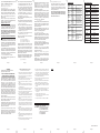
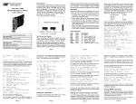
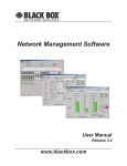
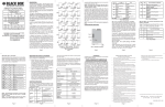
OVERVIEW:
DFCS NMM
Network Management Module
User’s Manual
Serial Console Port
BOARD MOUNTED SWITCH SETTINGS:
An NMM can be managed by DFCS SNMP-based DFCS
SNMP Management Software, third-party SNMP clients
or Telnet. Managment options include monitoring of module
statistics, trap notification and DIP-switch override
configuration of all DFCS modules in the managed chassis.
PORT STRUCTURE:
Serial Console Port:
The NMM features a Serial RS-232 Console Port (DB-9
Female) for the initial setup and configuration described in
this manual.
(2) Multi-Chassis
Daisy Chain Ports
Ethernet Front-Panel
Management Port
DFCS SNMP and Telnet Management Module
Model
Description
LMC3000A
SNMP and Telnet Management Module
Optional Accessories
LMC3001A
NMM Cascade Cable (3 ft.)
LMC3003A
Network Managment Software for Windows
9X/ME/XP/NT/2K
ABOUT THIS MANUAL
Multi-Chassis Daisy Chain Ports:
The NMM features a pair of multi-chassis daisy chain
ports, which are used to daisy chain (cascade) chassis
and to manage up to 19 chassis using a single IP address.
For more information about cascading chassis using
the multi-chassis daisy chain ports, refer to the DFCS
SNMP Management Software user manual.
Front-Panel and Backplane Management Ports:
The NMM features both front-panel and backplane 10Mbps
Ethernet management interface ports to facilitate SNMP
management of DFCS modules in a 2, 5 or 19-Module
chassis. Front-panel (Out-of-Band) management is
accomplished by attaching a Category 5 UTP cable to
the Ethernet front-panel Management Port, or by a modem
connection to the serial console port. For more
information about Out-of-Band management, refer
to the appropriate DFCS chassis user manuals.
This document supports revision “xx/32” of the NMM. Please
refer to the serial number label on the NMM for the revision
number of your product. This revision incorporates the
following improvement to the NMM:
1. Enhanced 802.3ah OAM mode support.
Page 1
6: Enable/Disable TELNET
7: Enable/Disable FTP
8: Enable/Disable Soft-switch Reload
9: Telnet Password
10: FTP Password
11: Serial Password
Enter Choice, Management Options Screen(0),
Help(h), Exit(x) >
To configure the IP address of the NMM, type 1 at the IP
and Control Preferences screen, and press <ENTER>.
Backspace over the existing value, type the new value
(in xxx.xxx.xxx.xxx format), and press <ENTER>.
To configure the Subnet Mask of the NMM, type 2 at the
IP and Control Preferences screen, and press <ENTER>.
Backspace over the existing value, type the new value
(in xxx.xxx.xxx.xxx format), and press <ENTER>.
To configure the Gateway of the NMM, type 3 at the IP
and Control Preferences screen, and press <ENTER>.
Backspace over the existing value, type the new value
(in xxx.xxx.xxx.xxx format), and press <ENTER>.
To save the new values, type 0 and press <ENTER> to
return to the Management Options screen and then
type 6 and press <ENTER> to Save Preference Changes.
Setting the Chassis Name and Number:
A Chassis Name, or sysName, can be assigned for
identification of the NMM in the SNMP client. The name
can be any 1 to 32 character alphanumeric string.
The Chassis Number can remain as 1 (factory default) when
the NMM is installed without another management module (a
DFCS media converter with integrated management such
as the DFCS10/100T-Fx Managed Module “10/100M”) in
the same chassis. When the NMM is installed in the same
chassis with another management module, they must all
be set to the same Chassis Number.
To set the Chassis Name, type 5 at the IP and Control
Preferences screen, press <ENTER> and follow the
instructions to enter the chassis name.
Chassis
Backplane
The DFCS Network Management Module (NMM) provides
Telnet and SNMP-based monitoring and control for the
DFCS product family. When an NMM module is installed
in an DFCS chassis, it provides management of all DFCS
modules in the chassis.
Fig. 1 Board Mounted Switches
Ethernet Crossover Switch:
When connecting the Ethernet front-panel management
port to a hub or switch, set the Ethernet Crossover Switch
to “Switch”. When connecting to a workstation, set to
“Workstation” (factory setting).
Ethernet Backplane Enable Switch:
When the Backplane Enable Switch “Ethernet Port” is in
the “Front” position (factory setting), the Ethernet
front-panel management port is enabled and the backplane
Ethernet port (Port “A”) is disabled. When the
“Ethernet Port” switch is in the “Back” position, the
front-panel port becomes disabled and the backplane port
is enabled. In this setting, the NMM module can
communicate with an adjacent module via the chassis
backplane.
IN-BAND MANAGED APPLICATION:
The 10 Mbps Ethernet backplane connects to an adjacent
DFCS module within the same DFCS chassis.
When the Ethernet backplane port of the NMM is enabled
using the board-mounted Backplane Enable Switch, it
connects the NMM via the chassis’ Backplane ‘A’ Link to
one of the slots adjacent to the NMM module. When
switch-based modules with backplane port connections
such as a DFCS 10/100T-100Fx TVLAN “10/100VT”
fiber-to-copper converter and an DFCS 4Tx/L2 “4Tx” fourport switch module are installed in the slots adjacent to
the NMM, they can be connected via the chassis’ Ethernet
backplane to facilitate a managed switch configuration.
Page 3
To save the new values, type 0 and press <ENTER> to
return to the Management Options screen, then type 6
and press <ENTER> to Save Preference Changes.
To set the SNMP Read Community Name, type 4 at the
SNMP Preferences screen, press <ENTER> and then
follow the screen prompts.
Setting NMM Passwords:
The NMM is shipped from the factory without password
protection on the Serial Console Port. It is highly
recommended that the network administrator set a
password in order to prevent unauthorized access to the
unit. The password can be any 1 to 32 character
alphanumeric string.
To set the SNMP Write Community Name, type 5 at the
SNMP Preferences screen, press <ENTER> and then
follow the screen prompts.
To set the password for Telnet access, type 9 at the IP
and Control Preferences screen, press <ENTER> and
then follow the screen prompts to enter and verify the
password. The default password for Telnet access is
“public”.
To set the password for FTP access, type 10 at the IP
and Control Preferences screen, press <ENTER> and
then follow the screen prompts to enter and verify the
password.
To set the password for serial access, type 11 at the IP
and Control Preferences screen, press <ENTER> and
then follow the screen prompts to enter and verify the
password.
To save the new values, type 0 and press <ENTER> to
return to the Management Options screen and then
type 6 and press <ENTER> to Save Preference Changes.
SETTING SNMP PREFERENCES:
To set the SNMP Preferences of the NMM, type 4 at the
Management Options screen, press <ENTER> and follow
the screen prompts.
To set the Chassis Number, type 4 at the IP and Control
Preferences screen, press <ENTER> and follow the
instructions to enter the chassis number.
Setting SNMP Read and Write Community Names:
Setting the SNMP Read and Write Community Names is
necessary for reading data from and writing data to the
NMM. The names can be any 1 to 32 character
alphanumeric strings.
Page 7
Page 8
To disable or enable the SNMP Agent, select 7 from the
Other Networking Features screen and follow the screen
prompts.
To disable or enable the SNMP Writes, select 8 from the
Other Networking Features screen and follow the screen
prompts.
To save the new values, type 0 and press <ENTER> to
return to the Management Options screen, then type 6
and press <ENTER> to Save Preference Changes.
The NMM is shipped from the factory with the SNMP
agent enabled. The default SNMP Read and Write
Community name is “public”.
Setting the SNMP Trap IP Host Addresses:
SNMP traps are used to report events that occur during
the operation of a network. Some traps may require the
attention of the network administrator. The NMM is capable
of sending SNMP traps to up to eight different SNMP
management stations (Traphosts).
To enter the IP address of the first Traphost Address, type
4 at the Management Options screen to access the SNMP
Preferences screen. Type 6 at the SNMP Preferences
screen and press <ENTER>. Backspace over the existing
value, type the new value (in xxx.xxx.xxx.xxx format), and
press <ENTER>. To enter the IP addresses of additional
trap-receiving Traphost Addresses, repeat this process for
the Other Networking Features screen.
To save the new values, select 0 and press <ENTER> to
return to the Management Options screen, then select 6
and press <ENTER> to Save Preference Changes.
ENABLING REMOTE OAM MANAGEMENT MODE
Remote OAM (Operations, Administration and
Maintenance) is a secure, IP-less management mode. To
Enable Remote OAM management mode, an NMM and a
Page 9
Slot 2
“A” Link
NMM
front /
back
select
B Port
Internal
10/100
switch chip
NMM UTP
10 port
NMM Module
Slot 3
“B” Link
A Port
A Port
Page 2
The NMM is shipped from the factory with Telnet enabled
and FTP disabled. From the IP and Control Preferences
screen, type 6 to enable or disable Telnet, and type 7 to
enable or disable FTP.
Slot 1
Fiber
100 port
UTP
10/100 port
10/100VT Module
A Port
B Port
Internal
10/100
switch chip
4-port 10/100 UTP
Switch
4Tx Module
Fig. 2 In-Band Managed Application
Fig. 2 depicts a chassis with three modules plugged into
three of its adjacent backplane slots. The modules have
their backplane Ethernet ports enabled and are connected
to adjacent modules via the “A” and “B” backplane links. In
this example, the NMM in Slot 1 connects to the DFCS
10/100VT in Slot 2 using the “A” backplane link.
The module in Slot 3 is an DFCS 4Tx 4-port 10/100 switch
module, and it connects via its “B” link backplane port to
the 10/100VT facilitating a 5-port 10/100 Ethernet switch
with a fiber uplink configuration.
This example shows how the NMM functions with other
DFCS modules to create flexible and effective managed
network switch configurations.
For additional information regarding individual
chassis “A” and “B” backplane links, refer to the
specific chassis’ user manual.
MOUNTING AND CABLE ATTACHMENT:
DFCS modules are hot-swappable and can be installed
into any chassis in the DFCS family.
1. After configuring the DIP-switches, carefully slide the
DFCS module into the installation slot, aligning the
module with the installation guides. Ensure that the
module is firmly seated against the Backplane.
3. If multi-chassis grouping is desired, connect the NMMs
together using the DFCS NMM Cascade Cable (Model
LMC3001A).
4. To configure the NMM via the serial console port,
connect the DB-9 female connector on the front-panel
of an NMM to the serial RS-232 port of a computer.
5. When Front-Panel (Out-of-Band) Management is
desired, attach the Ethernet Front-Panel Management
Port via a Category 5 UTP cable to a 10Base-T capable
Ethernet device.
INITIAL SETUP AND CONFIGURATION:
Initial configuration is required when using the DFCS NMM
for the first time. To configure, connect the NMM to a
DB-9 serial (RS-232) equipped computer that supports
terminal emulation software, such as HyperTerminal. The
NMM Serial Console Port is a mini DIN-6 female connector,
which can be changed to a DB-9 connector with the
included adapter. Connect one end of a serial cable to
the serial port of the computer and the other end to the
Serial Console Port of the NMM.
Start HyperTerminal (or other similar software) and select
the correct COM Port in the HyperTerminal “Connect To:”
window.
Ensure that the serial port of the computer is set as
follows:
Bits Per Second
57,600
Stop Bits
1
Data Bits
8
Parity
NONE
Hardware Flow Control
NONE
Power-up the chassis containing the NMM module and press
<ENTER> on the computer keyboard to bring up a command
line prompt in HyperTerminal. A new NMM module does not
have a password, and will skip the Password Entry screen
and go straight to the Management Options screen. If a
password has been previously set, the Password Entry
screen will be displayed. Type the password and press
<ENTER>. The NMM will respond with the Management
Options screen:
2. Secure the module by fastening the panel thumb screw
(attached to module) to the chassis front.
Page 4
Management Options DFCS, Serial Agent
Network Management
DFCS media converter with integrated management
(10/100M) must be installed in a chassis at the network
core. This chassis is the master chassis. Another media
converter with integrated management at the network
edge (a Network Interface Device, or NID) must be
connected to the it’s link partner converter at the network
core. For example, a 10/100M media converter module
installed in the master chassis is linked to a 10/100M
standalone converter (NID) at the network edge.
and follow the instructions to assign the PRI for the
Management Data.
This configuration enables the master chassis at the
network core to establish a Remote OAM management
channel between the link partners. The Remote OAM
management channel enables the NMM in the master
chassis to control up to 18 remote DFCS NIDs at the
network edge with one IP address.
Remote OAM consists of two types of IP-less
management channels, IEEE 802.3ah OAM and DFCS’
Secure OAM. Refer to the DFCS SNMP Management
Software user manual for more information on these two
types of IP-less management.
To set the Remote OAM Management Mode of the NMM
and chassis, type 9 at the Management Options Screen
and press <ENTER> to access the Other Networking
Features screen.
To select the Remote OAM management mode, type 10
at the Other Networking Features screen, press
<ENTER> and follow the screen prompts to change the
setting.
MANAGEMENT PROCESSOR VLAN SUPPORT:
The NMM Management Processor can independently
transmit and receive Management Data with the IEEE
802.1Q tag. To enable and configure this feature, type 9
from the Management Options screen to access the
Other Networking Features screen.
To configure IEEE 802.1Q VLAN ID (VID), type 3 at the
Other Networking Features screen, press <ENTER>
and follow the instructions to assign the VID for the
Management Data.
To configure IEEE 802.1p Priority (PRI), type 4 at the
Other Networking Features screen, press <ENTER>
Page 10
Page 5
To enable IEEE 802.1Q VLAN processing for the
Management Processor, type 2 at the Other Networking
Features screen, and follow the instructions to enable
VLAN processing.
To save the new values, type 0 and press <ENTER> to
return to the Management Options screen and then
type 6 and press <ENTER> to Save Preferences Changes.
Note that for more information on configuring the
switch VLAN capability, please refer to the DFCS
SNMP Management Software user manual.
ENABLING/DISABLING SOFT-SWITCH RELOAD:
The Soft-switch Reload function controls the configurations
of the NMM and other DFCS modules managed by the
NMM following a power-up.
When the Soft-switch Reload is disabled, the configurations
of the NMM and any other managed modules are determined
by their hardware DIP-switch settings. The DIP-switch
settings override any previous software settings stored in
the FLASH memory of the NMM.
When the Soft-switch Reload is enabled, the configurations
of the NMM and other managed modules are determined
by the previous software settings stored in the FLASH
memory of the NMM. In addition, the actual hardware DIPswitch settings of each module are ignored until a change
is made to the physical DIP-switch settings, then the new
physical DIP-switch settings of the module take effect.
To set the Soft-switch Reload function, type 8 at IP and
Control Preferences, press <ENTER> and then follow
the screen prompts to change the setting.
To save the new values, type 0 and press <ENTER> to
return to the Management Options screen and then
type 6 and press <ENTER> to Save Preference Changes.
ACCESSING THE NMM REMOTELY:
The NMM can be accessed remotely via SNMP, Telnet,
FTP or an external serial modem connected to the Serial
Console Port.
Page 11
1: Chassis and Module Management
2: Set Module Name
3: IP and Control Preferences
4: SNMP Preferences
5: Abandon Preference Changes
6: Save Preference Changes
7: Restore Factory Defaults
8: Restart
9: Other Networking Features
Management Module Maintenance
10: Firmware Update
11: Set Date/Time
IP Address = 192.168.1.220
Chassis Number = 1
Enter Choice, Help (h), Exit (x) >
Setting IP and Control Preferences:
An IP address is required for the SNMP manager to
address the NMM. The initial factory setting is
192.168.1.220. The IP address can be configured manually
or be assigned automatically by a DHCP server.
Setting IP Parameters as DHCP Client:
To configure the IP automatically as a DHCP client, type
9 from the Management Options screen. The Other
Networking Features screen will appear.
To enable DHCP client, type 1 at the Other Networking
Features screen and follow the screen prompts to enable
DHCP.
To save the new values, type 0 and press <ENTER> to
return to the Management Options screen, then type 6
and press <ENTER> to Save Preference Changes.
Setting IP Parameters Manually:
To manually configure the IP address and control
parameters, type 3 from the Management Options
screen. The IP and Control Preferences screen will
appear:
IP and Control Preferences Screen DFCS, Serial
Agent
1: Set IP
2: Set Subnet Mask
3: Set Gateway
4: Chassis Number
5: Chassis Name (also sysName)
Page 6
Accessing the NMM via SNMP:
The SNMP service can be remotely accessed by
SNMP-client software such as DFCS SNMP Management
Software or any third-party SNMP management software.
Note that for more information on using and
configuring the SNMP service, please refer to the
DFCS SNMP Management Software user manual.
Accessing the NMM via Telnet:
The NMM is shipped from the factory with Telnet enabled.
The default Telnet password is “public”. It is highly
recommended that the network administrator set a new
Telnet password in order to prevent unauthorized access
to the unit.
Telnet access can be enabled or disabled at the IP and
Control Preferences screen. This screen also contains
an option to set the Telnet password.
The NMM may be accessed and configured via Telnet
using any standard Telnet client. Only one Telnet session
can be active at a time. An inactive Telnet session
terminates automatically after five minutes.
Accessing the NMM via External Serial Modem:
The NMM can be accessed through an external modem to
provide remote access and management. Further
information can be obtained through Tech Support.
Accessing the NMM Trap Log via FTP:
FTP access is disabled by default, and can be enabled or
disabled at the IP and Control Preferences screen. This
screen also contains an option to set the FTP password.
To access the NMM via FTP, initiate an FTP application to
the NMM IP Address, log in as user “DFCS” and use the
FTP password assigned during the NMM configuration.
A copy of the SNMP trap log is in the FTP root directory.
The log can be downloaded with the FTP application.
UPDATING NMM FIRMWARE:
Updating the NMM firmware enables administrators to
upgrade the firmware within the management module and
take advantage of new features.
Updating the Firmware via the Serial Console:
To update the NMM firmware from the Serial Console,
Page 12
type 10 at the Management Options screen and press
<ENTER>. The NMM will display the following:
Enter Choice, Help(h), Exit(x) > 10
UPDATE: Are you sure? [Y/N] > Y
Please Xmodem file now:
From the terminal program, use the Xmodem protocol to
send the new NMM-xxx.bin firmware file to the NMM module
(where xxx represents the release level of the software).
a) To select a single chassis managed by the NMM, input
the assigned chassis number of the chassis. Valid
chassis number ranges from 1 to 19. e.g. chassis=7.
Once the file transfer begins, the data uploads to the
NMM. The process takes about five minutes over a
serial connection.
When the upload is complete, the update status is
displayed on the PC screen and the NMM automatically
restarts with the newly loaded firmware.
Updating the Firmware via FTP:
Using an FTP application, upload the new firmware into
the FTP root directory of the NMM. When the file transfer
is complete, the NMM verifies the file and then
automatically restarts with the newly loaded firmware.
Note that the firmware of DFCS management modules,
such as the NMM and the 10/100M, can only be updated
by directly accessing their own FTP server or through
their own Serial Console Port.
c) To select all the chassis managed by the NMM, input
ALL for the value. e.g. chassis=ALL
UPDATING OTHER MODULES’ FIRMWARE VIA
FTP:
In an DFCS chassis with other DFCS modules managed
by an NMM, the firmware of the other DFCS modules with
FLASH memory can be updated through the NMM’s FTP
server. This procedure requires an FTP application that
supports the ‘quote’ command (the ability to send literal
commands to the FTP server).
Log into the NMM’s FTP server with the FTP application.
Type the ‘quote’ command to input the chassis number
and slot number of the installed DFCS module(s) selected
for firmware update. The chassis and module selection
command uses the following syntax:
quote chassis=<RANGE1> module=<RANGE2>
Where <RANGE1> defines the target chassis in one of
the following methods:
Page 13
TRADEMARKS
All applied-for and registered trademarks are the
property of their respective owners.
FEDERAL COMMUNICATIONS COMMISSION AND
CANADIAN DEPARTMENT OF COMMUNICATIONS
RADIO FREQUENCY INTERFERENCE STATEMENTS
This equipment generates, uses, and can radiate radio
frequency energy and if not installed and used properly,
that is, in strict accordance with the manufacturer’s
instructions, may cause interference to radio
communication. It has been tested and found to comply
with the limits for a Class A computing device in accordance
with the specifications in subpart B of Part 15 of FCC
rules, which are designed to provide reasonable protection
against such interference when the equipment is operated in a commercial environment. Operation of this
equipment in a residential area is likely to be cause interference, in which case the user at his own expense will be
required to take whatever measures may be necessary to
correct the interference.
Changes or modifications not expressly approved by the
party responsible for compliance could void the user’s
authority to operate the equipment.
This digital apparatus does not exceed the Class A limits
for radio noise emission from digital apparatus set out in the
Radio Interference Regulation of the Canadian
Department of Communications.
Le présent appareil numérique n’émet pas de bruits
radioélectriques dépassant les limites applicables aux
appareils numéirques de las classe A prescrites dans le
Règlement sur le brouillage radioélectrique publié par le
ministère des Communications du Canada.
b) To select a range of chassis managed by the NMM,
input a range of chassis numbers. The range starts
with the lowest chassis number in the range, follows
by a hyphen “-” symbol and then ends with the highest
chassis number in the range. e.g. chassis=4-15.
Where <RANGE2> defines the target module(s) in one of
the following methods:
a) To select a single slot in the selected chassis, input the
slot number of the module. Valid slot number ranges
from 1 to 19. e.g. module=7.
b) To select a range of slots in the selected chassis, input
a range of slot numbers. The range starts with the
lowest slot number in the range, followed by a hyphen
“-” symbol and then ends with the highest slot number
in the range. e.g. module=4-15.
c) To select all the slots in the selected chassis, input
ALL for the value. e.g. module=ALL.
Here are some examples of valid chassis and module
selection command inputs:
quote chassis=1 module=3
quote chassis=ALL module=2-19
quote chassis=4-10 module=ALL
Inputting a valid chassis and module selection command
will return the text response Command Accepted from
the FTP server. Note that some FTP applications do not
display the text response from an FTP server by default.
Modules selected by the module selection command that
are not compatible with the new firmware are automatically
skipped during the update process.
After inputting the chassis and module selection command,
type the ‘quote’ command to input the flashstatus command.
The flashstatus command uses the following syntax:
quote flashstatus
After inputting the flashstatus command, the FTP server
should return Transfer the codefile now or
return Waiting for file to transfer, indicating
the NMM is ready to receive the new firmware. If the FTP
server does not return the expected replies, try inputting
the flashstatus command again.
Make sure the FTP application’s local directory is where
the firmware file is located. Type the ‘put’ command
followed by the firmware file name (or use the ‘upload’
function in a graphical FTP application) to upload the
firmware file from the local directory to the FTP server’s
root directory. The following is an example of uploading
the 10/100VT version 1.1 firmware file:
put 10-100VT.11
When the file transfer is complete, the NMM automatically
installs the new firmware on the selected DFCS module.
A DFCS module being updated blinks its LEDs in a
sequential strobe pattern.
-No programming in process
This response is returned when no module has been
selected by the chassis and slot selection commands.
Once the new firmware installation is successfully
completed, the selected DFCS modules will restart with
the newly installed firmware.
Note that the firmware of DFCS management modules,
such as the 10/100M and the NMM, can only be updated
by directly accessing their own FTP server or through
their own Serial Console Port.
LED INDICATORS:
LED
Function
"Legend"
Color
NMM SPECIFICATIONS
Off State
On / Blinking State
Protocols
IP, UDP, SNMP, TCP, ARP, ICMP,
Telnet, FTP
Module has power
Copper Connectors
Chassis
Power
Power Supply
Supply #1
Amber
#1 not
Status "PS1"
installed
On: Power available from
installed Power Supply #1
Blinking: No power available
from installed Power Supply #1
Controls
UTP Crossover, Backplane Enable
LED Displays
Pwr, Pwr Supply (3), Management
Link, Master/Slave, Mgt
Chassis
Power
Power Supply
Supply #2
Amber
#2 not
Status "PS2"
installed
On: Power available from
installed Power Supply #2
Blinking: No power available
from installed Power Supply #2
Chassis
Power
Power Supply
Supply #3
Amber
#3 not
Status "PS3"
installed
On: Power available from
installed Power Supply #3
Blinking: No power available
from installed Power Supply #3
Power "Pwr"
Amber No power
Supported MIBs
Dimensions
RJ-45, DB-9
RFC1155, RFC1156, RFC1157,
RFC1212, RFC1213, OST MIB
W0.85" x D:4.5" x H:2.8"
Weight
P o w er
Requirements
8 oz.
3.3VDC / 0.5Amp
Network Ports Status
When using the flashstatus command to check on the
progress of the firmware update, the NMM’s FTP server
will return one of the following responses:
-File download in process
This response is returned when the NMM’s FTP server is
receiving the firmware file from the FTP client or when
the NMM is installing the received firmware on the selected
DFCS module(s). The response also reports the progress
of the current module’s firmware installation.
Compliance
Management
Mode
"Msr/Slv"
Green Slave Mode
Management
Polling "Mgt"
No
Green Management Management Polling Activity
Polling Activity
Management
No
Port Link and
Green Management
Activity
Port Link
"Lk/Rx"
UL, CE, FCC, Class A, NEBS 3
Management Master Mode
On: 10Mbps Management Port
Link is active (via either UTP
or Backplane A)
Blinking: Management Port
Receiving Data
Operating Temp.
-Standard Model
0 to 50 C
Storage Temp
-40 to 80 C
Humidity
(non-condensing)
0-95%
Altitude
0 - 10,000 ft.
MTBF (hrs)
-Module programmed successfully
786,000
This response is returned when the NMM has finished the
firmware installation of the selected module(s), along with
the status of each selected module.
The status Slot # 100 Percent Complete indicates
the NMM has successfully installed the firmware of the
selected module in the Slot #.
The status Slot # Module file type error
indicates the received firmware is incompatible with the
selected module in the Slot # and the module was skipped
during the installation.
The status Slot # Module program failure
indicates the NMM was not able to complete the installation
of the firmware of the selected module in the Slot #.
Page 13
Page 14
NORMAS OFICIALES MEXICANAS (NOM)
ELECTRICAL SAFETY STATEMENT
1. Todas las instrucciones de seguridad y operación deberán
ser leídas antes de que el aparato eléctrico sea operado.
2. Las instrucciones de seguridad y operación deberán ser
guardadas para referencia futura.
3. Todas las advertencias en el aparato eléctrico y en sus
instrucciones de operación deben ser respetadas.
4. Todas las instrucciones de operación y uso deben ser
seguidas.
5. El aparato eléctrico no deberá ser usado cerca del agua—por
ejemplo, cerca de la tina de baño, lavabo, sótano mojado o
cerca de una alberca, etc.
6. El aparato eléctrico debe ser usado únicamente con carritos
o pedelstales que sean recomendados por el fabricante.
7. El aparato eléctrico debe ser montado a la pared o al techo
sólo como sea recomendado por el fabricante.
8. Servicio—El usuario no debe intentar dar servicio al equipo
eléctrico más allá a lo descrito en las instrucciones de operación.
Todo otro servicio deberá ser referido a personal de servicio
calificado.
9. El aparato eléctrico debe ser situado de tal manera que su
posición no interfiera su uso. La colocación del aparato
eléctrico sobre una cama, sofá, alfombra or superficie similar
puede bloquea la ventilación, no se debe colocar en libreros
o gabinetes que impidan el flujo de aire por los orificios de
ventilación.
10. El equipo eléctrico deber ser situado fuera del alcance de
fuentes de calor como radiadores, registros de calor, estufas
u ostros aparatos (incluyendo amplificadores) que producen
calor.
11. El aparato eléctrico deberá ser connectado a una fuente de poder
sólo del tipo descrito en el instructivo de operación, o como se
indique en el aparato.
12. Precación debe ser tomada de tal manera que la tierra fisica
y la polorizacion del equipo no sea eliminada.
13. Los cables de la fuente de poder deben ser guiados de tal
manera que no sean pisados ni pellizcados por objetos
colocados sobre o contra ellos, poniendo particular atención
a los contactos y receptáculos donde salen del aparato.
14. El equipo eléctrico debe ser limpiado únicamente de acuerdo
a las recomendaciones del fabricante.
15. En caso de existir, una antena externa deberá ser localizada
lejos de las lineas de energia.
16. El cable de corriente deberá ser desconectado del cuando el
equipo no sea usado por un largo periodo de tiempo.
17. Cuidado debe ser tomado de tal manera que objectos liquidos
no sean derramados sobre la cubierta u orificios de
ventilación.
18. Servicio por personal calificado deberá ser provisto cuando:
A: El cable de poder o el contacto ha sido dañado; u
B: Objectos han caído o líquido ha sido derramado dentro
del aparato; o
C: El aparato ha sido expuesto a la lluvia; o
D: El aparato parece no operar normalmente o muestra un
cambio en su desempeño; o
E: El aparto ha sido tirado o su cubierta ha sido dañada.
Page 15
Page 16
Page 18
NOTES:
CUSTOMER Order toll-free in the U.S.: Call 877-877-BBOX
SUPPORT (outside U.S. call 724-746-5500)
INFORMATION FREE technical support 24 hours a day, 7 days a
week; Call 724-746-5500 or fax 724-746-0746
Mailing address: Black Box Corporation,
1000 Park Drive, Lawrence, PA 15055-1018
Web site: www.blackbox.com
E-mail: [email protected]
040-L3000-001B 08/06
Page 19
Page 20
Page 21
Page 22
Page 23
Page 24