1
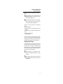
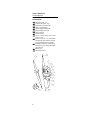
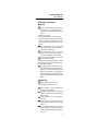
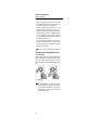
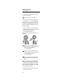
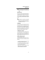
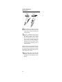
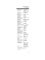
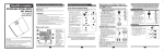
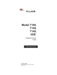
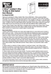
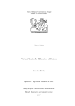
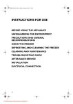
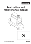
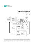
®
Model T100,
T120,
T140,
VDE
Voltage/Continuity
Tester
Users Manual
November 2006
© 2006 Fluke Corporation. All rights reserved.
Printed in China
Fluke T100/120/140
Introduction
References marked on instrument or in instruction manual:
Warning of a potential danger, comply with
instruction manual.
Reference. Please use utmost attention.
Caution! Dangerous voltage. Danger of
electrical shock.
Continuous double or reinforced insulation
complies with category II IEC 61140.
Symbol for the marking of electrical and electronic
equipment (WEEE Directive 2002/96/EC).
Suitable for live working.
VDE-approved, built- in compliance with
the valid directives.
Conformity symbol, the instrument complies with the valid directives. It complies
with the EMV Directive (89/336/EEC). It
also complies with the Low Voltage Directive (73/23/EEC).
Measuring Circuit
Category CAT III:
In addition to category II, the measuring circuit
category III includes electric equipment subject
to special demands with reference to safety
and availability.
Examples: House installations, protective
equipment, outlets, switches...
Measuring Circuit Category CAT IV:
Electric equipment, for which lightning voltage
must also be taken into consideration, belongs
to category IV. This includes, e.g. the connection to overhead circuits, underground cables to
water pumps...
The instruction manual contains information and references, necessary for safe
operation and maintenance of the instrument. Prior to using the instrument read
the instruction manual and comply with it
in all sections.
Failure to read the instruction manual or to
comply with the warnings and references
contained herein can result in serious bodily injury or instrument damage.
2
Fluke T100/120/140
Introduction
Introduction / Scope of Supply
The FLUKE T100/T120/T140 instruments are
voltage and continuity testers with rotary field
indication for universal applications. The voltage testers are constructed in accordance with
the newest safety prescriptions and guarantee
safe and reliable measurement and testing.
The risk of injury when transporting the instrument in clothing pockets or in the tool box is eliminated due to the fixed test probe cover, as required by VBG 1 (BG) § 35 (Transporting
Tools).
The voltage testers represent a valuable support for all testing and measurement in handicraft and industrial applications as well as for
household uses.
The voltage testers FLUKE T100/ T120/ T140
characterised by the following features:
• Constructed in compliance with DIN EN
61243-3, DIN VDE 0682 Part 401 (previously
DIN VDE 0680 Part 5), DIN VDE 0682 Part
401 A1, IEC61010
• Fixed test probe cover eliminates risk of i n jury (VBG 1, § 35 Transporting Tools)
• Digital LC-Display (only FLUKE T120/T140 )
• Resistance measurement (only T140 )
• LED (FLUKE T100)
• DC and AC voltage measurement up to 690V
• Single-pole phase test
• Continuity test / diode test
• Double-pole rotary direction determination
• IP 65 (IEC 60529, EN 60529,
DIN VDE 0470-1)
After unpacking, verify that the instrument is
undamaged. The scope of supply comprises:
1 FLUKE T100, T120 or T140
2 Batteries 1,5V IEC LR03 AAA
1 Users Manual
3
Fluke T100/120/140
Safety Measures
Safety Measures
The instruments FLUKE T100/T120/T140 have
been constructed and verified in compliance
with the safety measures for voltage testers
and have left the factory in safe and perfect
condition.
In order to avoid electrical shock, the valid
safety and VDE regulations regarding excessive contact voltages must receive utmost attention, when working with voltages exceeding 75V (60V) DC or 50V
(25V)rms AC. The values in brackets are
valid for spezial ranges (for example medicine and agriculture).
The detector shall not be used, if the battery box is open.
Prior to each test, ensure the proper condition of the measuring line and the measuring instrument, e.g. broken cables or
leaking batteries.
Prior to measurement ensure that the test
leads and the test instrument are in perfect condition.
When using this instrument only the handles of the probes may be touched .
This instrument may only be used within
the ranges specified (see 6.0 Technical
Data) and within voltage systems up to
690V
The measuring instrument may be used only in
the measuring circuit category it has been designed for!
Instrument's faultless functionality must be verified prior to every use.
1) Short-circuit the probes. The Rx/Ohm LED
must light up. If not, remove/replace the
batteries.
2) Test the voltage tester on a known voltage
source.
Prior to usage ensure perfect instrument
function (e.g. on known voltage source).
The voltage testers may no longer be used
if one or several functions fail or if no
functionalityis indicated.
4
Fluke T100/120/140
Safety Measures
Do not measure under damp conditions.
Perfect display is only guaranteed within a
temperature range of -10°C up to + 55°C,
at relative humidity <85%
If the operator’s safety cannot be guaranted, the instrument must be removed from
service and protected against use.
Safety is no longer ensured in the following
cases:
• Obvious damage
• When the device no longer performs the desired tests
• Excessive storage under unfavourable conditions
• Strain through transport
• Leaking batteries
For all the work, the accident prevention regulations of the commercial and industrial worker's
compensation insurance carriers for electric installations and equipment must be heeded.
Appropriate Usage
The instrument may only be used under those
conditions and for those purposes for which it
was built. For this reason, in particular the
safety references , the technical data including
environmental conditions and the usage in dry
environments must be followed.
When modifying or changing the instrument, the operational safety is no longer
ensured.
The instrument may only be opened by an
authorised service technician, e.g. for fuse
replacement.
5
Fluke T100/120/140
Control Elements
Control Elements and
Connections
1
2
3
4
5
6
7
8
9
10
11
12
13
Handle test probe - (L1)
Instrument test probe + (L2)
Measurement point illumination
LEDs for voltage display
LED for single-pole phase test
LED for left/right rotary field
LED for continuity
Polarity indication
LCD for voltage display (only FLUKE
T120 and T140)
Button on rear side - for measurement
point lightning (Also resistance measurement and RCD Trip Test in T140VDE)
Accessible electrode for double-pole determination of phase rotation and singlepole phase test
Battery case
Test probe protection
2
1
3
4
5
6
7
8
9
10
11
13
6
12
Fluke T100/120/140
Users Manual
Carrying out Measurements
Preparation and Safety
Measures
For any test (measurement) the safety references have to be respected. Prior to
any usage, a functional test has to be carried out.
Function test / Self test:
• Test the voltage tester on a known source.
• Connect the probes. A sound must be heard
and the Rx/1 LED (7) must be lit. If the LED
does not light up, the batteries need to be replaced.
The voltage display of the instruments
also functions when using discharged or
no batteries > 20 V (LCD).
The voltage testers may no longer be
used if one or several functions fails or if
no functional reliability can be detected.
Remove discharged batteries from the device to prevent any leaks.
The instruments are equipped with an internal
load enabling the tripping of an RCD protection
device of 10mA or 30mA.
For voltage tests (L towards PE) in systems with RCD devices, the RCD may be
triggered. To avoid RCD tripping first test
between L and N (approx. 5s). Immediately afterwards testing L towards PE can be
carried out without RCD tripping (not T140
VDE)
Voltage Test
Safety measures have to be met
• Connect both test probes with UUT.
From a voltage of < 12V the voltage tester
switches on automatically.
The voltage is indicated by LED (4) and for
models FLUKE T120 and T140 also with a
digital LCD (9).
For AC voltages the ”+” and ”-” LEDs are illuminated.
For DC voltage, the polarity of the voltage
displayed refers to the instrument test
probe (+).
Due to technical reasons the instrument
cannot effectuate an automatic switch-on
for DC voltages within the range of approx.
0V to -3V.
7
Fluke T100/120/140
Users Manual
Single-Pole Phase Test
• To carry out single-pole phase tests ouch the
Accessible electrode (11) and connect instrument test probes to unknown contact.
• The single-pole phase test starts at an AC
voltage of approx. 100V (pole > 100V AC).
• When using single-pole phase tests to determine external conductors the display function
may be impaired under certain conditions
(e.g. for insulating body protective equipment
on insulation locations).
• The single-pole phase testing is not appropriate to determine whether a line is live or
not. For this purpose, the double-pole voltage
test is always required.
The LED (5) is illuminated in the display.
Voltage Test with RCD Trip Test
(not T140 VDE)
During voltage tests in systems equipped with
RCD circuit breakers, a RCD switch can be tripped at a nominal residual current of 10mA or
30mA by measuring the voltage between L and
PE.
The RCD trips.
To avoid RCD tripping a test has to be carried out between L and N during approx.
5s. Immediately afterwards, voltage testing between L and PE can be carried out
without RCD tripping.
8
Fluke T100/120/140
Users Manual
Voltage Test with RCD Trip Test
(only T140 VDE)
1)
2)
3)
Press Button on rear side measurement point light (10).
Measure between L and PE.
The RCD is tripping
The RCD could be so long tripped like the
measuring point lighting is active and L is
measured against PE. After a voltage test
wait approx.. 50 seconds to trip the RCD
again.
Restistance Test (only T140 /
T140 VDE)
Make sure that UUT is not live.
• Check that UUT is not live by carrying out a
double-pole voltage test.
• Connect both test probes with UUT. Press
Button on rear side - for measurement point
light (10) and read value on the display.
The resistance range is 1…1999 1 at a
resolution of 1 1.
The resistance test is active for 20 seconds after having pressed the button on
the rear.
If during the resistance measurement a
voltage is present the instrument switch
automatically to voltage measurement.
Continuity Test / Diode Test
Make sure that UUT is not live. Test voltage polarity at handle test probe is positive
(+).
• Check that UUT is not live by carrying out a
double-pole voltage test.
• Connect both test probes with UUT. A signal
sound is audible for continuity and the LED
for continuity Rx/1 is illuminated.
9
Fluke T100/120/140
Users Manual
Rotary Field Indication
The voltage testers are equipped with a doublepole rotary field indicator.
The safety measures have to be met
The rotary phase indication is always active.
The symbols R or L are always displayed.
However, the rotary direction can only be determined within a three-phase system. Here, the
instrument indicates the voltage between two
external conductors.
• Connect the instrument test probe with the
supposed phase L2 and the handle test
probe with the supposed phase L1.
• Touch Accessible electrode (11).
The voltage and the rotary field direction are
displayed.
L2
L2
L3
L3
L1
L1
N
N
PE
PE
R
L
R
signifies that the supposed phase L1 is
the actual phase L1 and the supposed
phase L2 is the actual phase L2
==> right rotary field
L
signifies that the supposed phase L1 is
the actual phase L2 and the supposed
phase L2 is the actual phase L1
==> left rotary field.
When re-testing with exchanged test probes the opposite symbol has to be illuminated.
Measurement Point Illumination
Voltage testers T100re equipped with a measurement point illumination feature. Thus, working
under bad lighting conditions (e.g. division
switch cabinets) is made easier.
• Press button for measurement point illumination (10) on instrument rear.
10
Fluke T100/120/140
Maintenance
The measurement point illumination is
active during approx. 45 seconds (only
T140).
Maintenance
When using FLUKE T100/T120/T140 testers in
compliance with the instruction manual, no particular maintenance is required. If functional errors occur during normal operation, stop using
it and contact your nearest authorized service
center.
If the device is not used for an extended
period of time, the batteries must be removed to prevent the risk of leaking batteries
and damage to the device.
Cleaning
Prior to cleaning, remove voltage tester from all
measurement circuits. If the instrument is dirty
after daily usage, it is adviseable clean it by
using a damp cloth and a mild household detergent. Never use acid detergents or dissolvents
for cleaning. After cleaning, do not use the voltage tester for a period of approx. 5 hours.
Calibration Interval
The voltage testers must be calibrated periodically and checked by our service department at
regular intervals to ensure the specified accuracy of measurement results. We recommend a
calibration interval of one year.
Battery Replacement
If the Rx/1 LED does not light up when the probes are short-circuited, the batteries must be
replaced.
• Completely disconnect FLUKE T100/ T120/
T140 from the measurement circuit.
• Turn the battery case in direction of the arrow
(e.g. using a coin). Then open and remove it.
• Remove discharged batteries.&
• Replace with new batteries, type 1.5V IEC
LR03 AAA respecting correct polarity.
• Insert the battery case and close it.
11
Fluke T100/120/140
Maintenance
1
O
PE
N
2
OPEN
4
3
1,5
VM
icro
IEC
LR03
+
LR0
3
1,5
VM
icro
IEC
LR03
+
When batteries have leaked, the device
must not be used any longer. Before you
can use it again, it must be checked by our
customer service.
Never try to dismantle a battery cell! The
electrolyte in the cell is extremely alkaline
and electroconductive. Risk of alkali
burns! If electrolyte comes into contact
with your skin or clothing, these spots
must be rinsed with water immediately. If
electrolyte got into your eye(s), rinse it
(them) with water immediately and seek
medical assistance.
Please consider your environment when you
dispose of your one-way batteries or accumulators. They belong in a rubbish dump for hazardous waste. In most cases, the batteries can be
returned to their point of sale.
Please, comply with the respective valid
regulation regarding the return, recycling
and disposal of used batteries and accumulators.
12
Fluke T100/120/140
Technical Data
Technical Data
LED voltage range ............12...690V AC/DC
LED resolution....................±12, 24, 50, 120, 230,
400, 690V
Tolerance............................complying to DIN VDE
0682, Part 401
LCD voltage range*............12V...690V AC/DC
LCD resolution* ..................1V
Tolerance* ..........................±(3% rdg. + 5 digits)
Voltage detection................automatic
Polarity detection................full range
Range detection ................automatic
Response time ..................<0.1s LED / <2s LCD
Frequency range ................0...400Hz
Automatic load (RCD) ........yes
Internal basic load..............approx. 2.1 W at 690V
Peak current ......................Is<0,3A(5s), In<3,5mA
Operation time....................ED (DT) = 30s
Recovery time ....................240 seconds
Auto Power On ..................<12 V AC/DC
Single-pole Phase Test
Voltage range ....................100...690V AC
Frequency range ................50...400Hz
Resistance Measurement**
0...19991/11
Tolerance** ........................ ± (3 % rdg. + 10
digits) at 20 °C
Temperature coefficient: ....± 5 digits / 10 K
Test current**......................<150µA
Overvoltage protection** ....690V AC/DC
Continuity Test..................0...400k1
Accuracy ............................RN +50%
Test current ........................< 5µA
Overvoltage protection ......690V AC/DC
Rotary Field Indication
Voltage range (LEDs) ........100...690V
Frequency range ................50...60Hz
Measurement principle ......double-pole and
Accessible electrode
Power supply...................... 2 x 1.5 V Micro IEC
LR03
Power consumption............max. 30mA / approx.
250mW
Temperature range ............-10°C...55°C
Humidity ............................max. 85% relative
humidity
Height above sea level ......up to 2000 m
Measurement category ......CAT IV / 600V
..........................................CAT III / 690V
Pollution degree ................2
Protection degree ..............IP65
Safety complying to............DIN EN/IEC 61243-3,
DIN VDE 0682 Part
401 (first DIN VDE
0680 Part 5, EN
61010, IEC 61010)
Weight ................................180g (incl. batteries)
Dimensions (HxWxD) ........240 x 56 x 24mm
* only T120,T140, T140VDE / ** only
T140,T140VDE
13
Fluke T100/120/140
Warranty
LIMITED WARRANTY & LIMITATION OF
LIABILITY
This Fluke product will be free from defects in
material and workmanship for one year from thedate of purchase. This warranty does not cover
fuses, disposable batteries, or damage fromaccident, neglect, misuse, alteration, contamination,
or abnormal conditions of operation orhandling.
Resellers are not authorized to extend any other
warranty on Fluke’s behalf. To obtainservice
during the warranty period, contact your nearest
Fluke authorized service center to obtainreturn
authorization information, then send your defective tester to that Service Center with adescription
of the problem.
THIS WARRANTY IS YOUR ONLY REMEDY. NO
OTHER WARRANTIES, SUCH AS FITNESSFOR
A PARTICULAR PURPOSE, ARE EXPRESSED
OR IMPLIED. FLUKE IS NOT LIABLE FORANY
SPECIAL, INDIRECT, INCIDENTAL OR CONSEQUENTIAL DAMAGES OR LOSSES,ARISING
FROM ANY CAUSE OR THEORY.
Since some states or countries do not allow
theexclusion or limitation of an implied warranty
or of incidental or consequential damages, thislimitation of liability may not apply to you.
Fluke Corporation
P.O. Box 9090
Everett WA
98206-9090
14
Fluke Europe B.V.
P.O. Box 1186
5602 B.D. Eindhoven
Netherlands