1
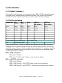
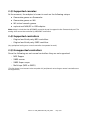
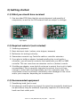
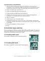
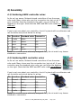
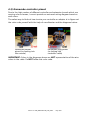
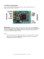
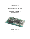
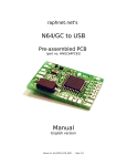
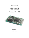
raphnet technologies
Nes/Snes to GC/Wii
Pre-assembled PCB
(part no. #BRD-NSNES-GCWII)
Manual
English version
Manual no. #M_NSNESTOGCW_PCB_ENG3 -
Page 1/10
Table of Contents
1) Introduction.........................................................................................................3
1.1) Product summary..........................................................................................3
1.2) Button mapping............................................................................................3
1.3) Supported consoles.......................................................................................3
1.4) Supported controllers....................................................................................4
1.5) Unsupported controllers................................................................................4
2) Getting started....................................................................................................5
2.1) What you should have received....................................................................5
2.2) Required material (not included)..................................................................5
2.3) Recommended equipment............................................................................5
2.4) Overview of installation................................................................................6
3) Controller type selection......................................................................................6
3.1) Enabling SNES mode.....................................................................................6
3.2) Enabling NES mode.......................................................................................6
4) Assembly.............................................................................................................7
4.1) Soldering SNES controller wires....................................................................7
4.2) Soldering NES controller wires......................................................................7
4.3) Gamecube controller pinout..........................................................................8
4.4) PCB wiring diagram.......................................................................................9
5) Copyright, Disclaimer and History.....................................................................10
5.1) Copyright....................................................................................................10
5.2) Disclaimer...................................................................................................10
5.3) Firmware License and source code.............................................................10
5.4) Revision history...........................................................................................10
Manual no. #M_NSNESTOGCW_PCB_ENG3 -
Page 2/10
1) Introduction
1.1) Product summary
This small circuit's purpose is to convert either a NES or SNES compatible game
controller to the Gamecube/Wii controller protocol. This circuit can be easily
installed inside an original controller or can be used to build an adapter.
1.2) Button mapping
Gamecube NES
NES
Snes
SNES in
NES mode 1
SNES in
NES mode 2
Start
Start
Start
Start
Select
Select
Select
Select
Select
D-Pad
D-Pad
D-Pad
D-Pad
D-Pad
(mode 1)
(mode 2)
Start
Start
Z
D-Pad
Y
Y
X
X
B
B
A
B
Y
B
A
A
B
A
B
Y
C-Stick right A+B+Select+left
L+R+Select+left
L+R
A+B+Select+Up
“SNES in NES mode” is useful for playing NES games with an SNES controller.
Mappings with a colored background are for special purposes such as opening
emulator menus. When of these combinations is detected, the adapter sends the
corresponding gamecube event and waits until all buttons are released before
continuing to work normally.
With a NES controller:
•
NES mode 1: Defaut
•
NES mode 2: Hold A and B when connecting the adapter
With and SNES controller:
•
SNES mode: Default
•
SNES in NES mode 1: Hold START when connecting the adapter
•
SNES in NES mode 2: Hold START, Y and B when connecting the adapter.
Manual no. #M_NSNESTOGCW_PCB_ENG3 -
Page 3/10
1.3) Supported consoles
At the moment, the adapter is known to work on the following setups:
●
Gamecube games on Gamecube
●
Gamecube games on Wii
●
Wii virtual console games
●
raphnet.net N64/GC to USB adapter.
Note: Keep in mind that the NES/SNES controller d-pad is mapped to the Gamecube d-pad. The
analog stick cannot be controller by NES/SNES controllers.
1.4) Supported controllers
•
Original and third party NES controllers.
•
Original and third party SNES contrllers.
(Any peripheral acting as a normal controller is expected to work).
1.5) Unsupported controllers
Since the following are not normal controllers they are not supported:
•
NES Zapper
•
SNES mouse
•
SNES Super scope
•
Multi-taps (NES or SNES)
(The list above is not meant to be complete. All peripherals not acting as normal controllers are
not supported.)
Manual no. #M_NSNESTOGCW_PCB_ENG3 -
Page 4/10
2) Getting started
2.1) What you should have received
1. One two-sided PCB. Note that the actual placement and quantity of
components, as well as the PCB artwork itself are subject to changes.
Top layer
Bottom layer
2.2) Required material (not included)
1. Soldering equipment.
2. Basic electronic tools. (cutters, wire stripper, tweezers)
3. Multimeter for testing continuity.
4. Gamecube connector. eg: Controller cable or controller extension.
5. If you plan to build an adapter (instead installing the circuit inside a
controller), you will need a connector that mates with your NES or SNES
controller. This can come from an extension cord or a (broken) console.
6. If building an adapter, some kind of enclosure to protect the circuit is highly
recommended. This is especially important to prevent the circuit from
coming in contact with anything metallic such as a computer case. This
could cause a short circuit which could likely cause damages to the circuit
and/or your computer, depending on circumstances.
2.3) Recommended equipment
1. Desoldering braid (just in case)
2. Hot glue gun and Hot glue (to prevent the wires from eventually breaking at
the point where they are soldered). Especially important if the wires may
bend near their solder point.
Manual no. #M_NSNESTOGCW_PCB_ENG3 -
Page 5/10
2.4) Overview of installation
1. Start by carefully planning how you will install the circuit inside the
controller (or your enclosure). Make sure you dont cut the wires too short
and that the circuit will not be in the way when you put back the cover.
2. Select controller type (see section 3)
3. Solder the Gamecube wires (see section 4)
4. Solder the NES and SNES wires (see section 4)
5. Double check wiring and inspect for shorts. Double-checking with a
multimeter is recommended if you have any doubts.
6. Test on a console.
7. Install hot glue over the solder points.
8. Insulate any metal part in the vicinity (e.g. Cable shields, unused wires,
enclosure...) which could come in contact with the Circuit. Use electric tape
or hot glue.
9. Finish the installation. (Close enclosure)
10. Play!
3) Controller type selection
The circuit supports 3 different modes (SNES, NES and DB9 mode). The mode is
selected by connecting (or not connecting) parts of JP1 and JP2. JP1 and JP2 are
checked by the firmware at power-up or reset.
3.1) Enabling SNES mode
Snes mode is enabled by not connecting anything.
3.2) Enabling NES mode
Nes mode is enabled by connecting JP1 pads together.
Manual no. #M_NSNESTOGCW_PCB_ENG3 -
Page 6/10
4) Assembly
4.1) Soldering SNES controller wires
As far as I am aware, Nintendo brand controllers all use the same
color code. Many clones also use this convention too, but not all. If
your controller uses the standard color code, you can follow the
diagram on the right. (Note that the SNES and NES color codes are
different).
If you're not sure about your controller, check it's pinout with a multimeter and
use the table and picture below for wiring:
Pin Function Standard color Connect to
1
5 volts
White
+
2
Clock
Yellow
PC5
3
Latch
Orange
PC4
4
Data
Red
PC3
7
Ground
Brown
Note: Pin numbers were arbitrarily assigned. They do not match any known
standard or convention.
4.2) Soldering NES controller wires
As far as I am aware, Nintendo brand controllers all use the same
color code. Many clones use this convention too, but not all. If your
controller uses the standard color code, you can follow the diagram
on the right. (Note that the SNES and NES color codes are different).
If you're not sure about your controller, check it's pinout with a multimeter and
use the table and picture below for wiring:
Pin Function Standard color Connect to
1
Ground
Brown
-
2
Clock
Red
PC5
3
Latch
Orange
PC4
4
Data
Yellow
PC3
7
5 volts
White
+
Note: Pin numbers were arbitrarily assigned. They do not match any known
standard or convention.
Manual no. #M_NSNESTOGCW_PCB_ENG3 -
Page 7/10
4.3) Gamecube controller pinout
Due to the high number of different controller and extension brands which use
varying color schemes, I cannot provide an universal wiring diagram based on
wire colors.
The safest way to find out how to wire your controller or adapter is to figure out
the color code yourself with the help of a multimeter and the diagrams below:
Gamecube socket
pinout (or looking into
the console)
Gamecube plug pinout
(or looking into
controller cable)
IMPORTANT: Colors in the diagrams above are NOT representative of the wire
colors in the cable. Do NOT follow this color code.
Manual no. #M_NSNESTOGCW_PCB_ENG3 -
Page 8/10
4.4) PCB wiring diagram
Once you know which wire does what in your cable, solder them to the
appropriate locations on the PCB:
IMPORANT: Solder the Gamecube data wire to the location labelled Data2
above. On older PCB versions (2012 or earlier) the gamecube data wire should be
connected to Data instead of Data2. If in doubt, trying out either location (or
even connecting them together) is safe.
Hints:
➢
Pre-tinning solder points on the PCB and the wires greatly eases soldering.
➢
Twists the two Gamecube Gnd wires together and pre-tin them before
soldering both of them on the PCB.
Manual no. #M_NSNESTOGCW_PCB_ENG3 -
Page 9/10
5) Copyright, Disclaimer and History
5.1) Copyright
All the information, pictures, diagrams, tables and texts contained within this
manual are Copyright © 2007-2014 Raphaël Assénat. All rights reserved. Partial or
total reproduction is not permitted without the Copyright holder's written
authorization, except for personal use.
Trademarks that are mentioned in this manual are the property of their respective
owners.
5.2) Disclaimer
Even though I made great efforts and a lot of testing to make sure my products
are safe, I cannot be held responsible for any damage(s) or loss(es) caused
directly or indirectly by the use of my products, including but not limited to, loss of
data, loss of profit, computer/server downtime, device and peripheral damage or
failure.
While I believe that all the information contained in this manual is accurate,
should any damage(s) occur due to error(s) in this manual, my responsibility will
be limited to replacing my product if it is damaged.
5.3) Firmware License and source code
The firmware source code is available under the terms of the GPL license and may
be downloaded from:
•
http://www.raphnet.net/electronique/x2wii/index_en.php
5.4) Revision history
February 17, 2008
First version of this manual.
January 18, 2012
Update for new GC data wiring
August 02, 2014
Button mapping and GC data wiring update.
Manual no. #M_NSNESTOGCW_PCB_ENG3 -
Page 10/10