1
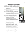
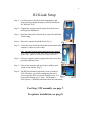
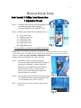
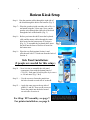
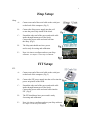
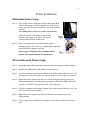
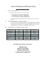
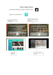
1
Aetrex Kiosk
Installation
Manual
Millennium
R2
Horizon
July 21, 2006
2
Millennium Kiosk Installation
Page 3
R2 Kiosk Installation
Page 4
Horizon Kiosk Installation
Page 5
And
Page 6
iStep Pressure Plate and FIT Scanner
Page 7
Printer Installation
Page 8
Aetrex Return Policy, Help Desk and Support Information
Page 9
3
Millennium Kiosk Setup
Step 1— Remove Kiosk from the shipping box carefully and
inspect the unit. (Report damage to Aetrex Worldwide,
Inc. 800-644-3514)
Step 2— Remove the outer back panel of the kiosk to expose the
shelf and kiosk wiring. (Fig.1)
Step 3— Using a Phillips head screwdriver, adjust the keyboard
and mouse tray to the upright position. Place the
keyboard and mouse on the tray. Take the end of the
keyboard and mouse cables and insert them into the hole
on the right side of the kiosk. (Fig. 2)
Step 4— Unpack the computer and begin the installation.
Step 5— Locate the wires behind the kiosk and connect them to
the computer. Cables are color coded.
Note: The following items must be plugged into the
Computer: Power cables, Touch screen USB cable, video cables,
keyboard, mouse, speaker cable and kiosk fans. Don’t forget to
switch the power strip to the on position and make sure all cables
are securely connected.
Step 6— All power supplies must be plugged into the power strip
provided inside the kiosk. (Fig. 3)
Step 7— At the back of the Kiosk, you will find a push button on
the upper right hand side of the kiosk. This is your
power on/off switch. The other end of this wire must be
plugged into the computer where you see a little sticker
marked POWER. This is how your computer is
started. (Note: older Millennium kiosks may have the
power button located on the side.)
For iStep / FIT assembly, see page 7.
For printer installation, see page 8.
4
R2 Kiosk Setup
Step 1— Carefully remove Kiosk from the shipping box and
inspect the unit. (Report damage to Aetrex Worldwide,
Inc. 800-644-3514)
Step 2— Unpack the computer and the printer from their boxes
and begin the installation.
Step 3— Open the front panel of the kiosk to expose the shelf and
kiosk wiring.
Step 4— Place the computer inside the kiosk. (Fig 1)
Step 5— Locate the wires inside the kiosk and connect them to the
computer. Cables are color coded.
Note: The following items must be plugged into the computer:
power cables, touch screen USB, video cables, keyboard, mouse and
speaker cable. (Make sure all cables are securely connected .)
Step 6— All power supplies must be plugged into the power strip
provided inside the kiosk.
Step 7— Turn on the computer and get ready to calibrate your
touch screen monitor. (Fig 3)
Step 8— The R2 Kiosk monitor and touch screen are made by
ELO. Therefore, you will be configuring the touch
screen using the ELO icon on the desktop screen. If it
is not on the desktop, go to Start > All Programs >
ELO System > Calibration and then follow the instructions.
For iStep / FIT assembly, see page 7.
For printer installation, see page 8.
5
Horizon Kiosk Setup
Step 1— Carefully remove Kiosk from the shipping box
and inspect the unit. (Report damage
to Aetrex Worldwide, Inc. 800-644-3514)
Step 2— Identify each of the Kiosk components (Fig. 1)
A – Top Center Unit
B – Bottom Center Unit
C1– Left Upper Unit
C2– Left Bottom Unit
D1– Right Upper Unit
D2– Right Bottom Unit
Two people are needed to assemble this kiosk.
(Note: Remove the back panel from Section B and check the welded areas and areas where the flat base
is connected to the base. If it appears that the welded area is cracked or that any screws have been shaved
or broken off, STOP—DO NOT ASSEMBLE THE KIOSK. (Report
damage to Aetrex Worldwide, Inc. 800-644-3514)
Step 3— Assemble section A on top of section B.
The top unit weighs about 50 lbs and 2 people are
necessary for assembly. Section A must rest
flush on top of section B unit. Open the back
panel of section A (Fig. 2). Once opened,
Section A has 4 holes inside the bottom unit
that will align over section B.
Step 4— Once opened, you will find several screws needed
to assemble the kiosk. Open the bag filled with
screws and take out 4 screws. (Fig. 2)
Step—5 Use 4 screws to secure section A onto section
B (Fig. 3).
6
Horizon Kiosk Setup
Step 6– Run the monitor cables through the right side of
the kiosk through the hole to the bottom. (Fig. 3)
Step 7— Place the speakers inside on either side of Sec. A
and attach using the Velcro tape. Next, run the
speaker wires through the right side of the kiosk
through the hole to the bottom. (Fig. 3)
Step 8— Before you insert the shelf, insert the keyboard
cable and the mouse cables through the center
hole located on the bottom area of Section A
(Fig. 4). To assemble the keyboard shelf, insert
the shelf into the front of Section A located at
the bottom area.
Step 9— Place the tray flush against Section A and
affix the unit with 2 1/4 inch nuts from the back of
Section A.
Side Panel Installation:
(2 people are needed for this setup.)
Step 10 - Now it is time to assemble the side panel
components. Start with the bottom panel of
C2 or D2. Each panel is held in place by 6 screws
or 1/8 inch nuts. (Fig. 5 & 6)
Step 11 — Use the screws to fasten the panels into
the holes located on each side of section B.
Step 12 — Apply the same steps to the top side of
panels C1 and D1. Now use the screws to
fasten the panels into the holes located
on each side of section A.
For iStep / FIT assembly, see page 7.
For printer installation, see page 8.
7
iStep Setup:
iStep:
A-
Connect one end of the serial cable to the serial port
on the back of the computer. (Fig. 2)
B-
Connect the iStep power supply into the wall
or into the power strip inside of the kiosk.
C-
Extend the other end of the power and serial cable
inside through bottom area of the kiosk.
Connect the power cable and serial call into
the iStep. (Fig.3)
D-
The iStep unit should now have power
and is ready for testing and calibration.
E-
Now it is time to configure and test your iStep
software. See chapter 2 of the iStep User Manual.
FIT Setup:
FIT:
A-
Connect one end of the serial cable to the serial port
on the back of the computer. (Fig. 2)
B-
Connect the FIT power supply into the wall or into the
power strip inside of the kiosk.
C-
Extend the other end of the power and serial cable
inside through bottom area of the kiosk.
Connect the power cable and serial cable into the
FIT. (Fig.5)
D-
The FIT should now have power and is ready
for testing and calibration.
E-
Now it is time to configure and test your iStep software.
See chapter 2 of the iStep User Manual.
8
Printer Installations
Millennium Printer Setup:
Step 1— Turn on the printer and prepare to adjust the printer shelf.
Position the printer tray flush with the back of the kiosk
printer opening. The paper should flow easily through the
opening.
Note: Phillips head screwdriver is needed to adjust the shelf.
(Note: For the HP 3940 printer, paper will be
inserted via the paper tray. Paper will also be
extracted from the front of the kiosk.
Step 2— Run a few printer tests to confirm that the paper is
printing properly. If it is not, try re-adjusting the paper tray
until the printer is printing correctly.
Don’t forget to install printer cartridges into the
printer. (See printer manual for instructions.)
Wireless Bluetooth Printer Setup:
Step 1— Install the printer drivers into the computer before attaching the wireless adapter.
Step 2— Replace the USB printer cable with the wireless device.
Step 3— Go to the computer control panel. Double click on the printer and faxes icon. You
will see the icon for your printer. (A separate printer icon may appear by default.)
Step 4— Right click on the printer icon and go to the tab marked Properties, then go to
the tab marked Ports. Scroll down to port marked USB001 or USB002 and make
sure one is checked. If one does not work, try the other one.
Step 5— Go to the computer control panel. Double click on the printer and faxes icon. You
will see the icon for your printer.
Step 6— Right click on the printer icon and scroll down to set the printer up as the
default printer.
Step 7— Turn on the printer and reboot the computer. Your printer should now be able to
print.
9
Aetrex Warranty and Return Policy
Aetrex Policy for Defective Computers
I.
Under-warranty computers
HP and Dell computers come with a 1-year on-site warranty.
•
•
•
Dell Technical Service Number # (800) 822-8965
HP Technical Service Number # (800) 652-6672
Aetrex Technical Service Number # (800)644-3514
Please call the appropriate phone number and have a technician come out to service the
computer.
II.
Out of warranty computers – customer has 2 options:
1. We will do our best to repair the computer in a timely manner (approx. 2-3 business
days). This service will be provided at no cost, but if the computer cannot be fixed, the
customer will need to purchase a new computer. The customer is also responsible for
the freight charges each way, but the service is FREE for iStep customers.
III.
Price charting for new and replacement hardware devices:
Kiosk
List Price
iStep Customer’s Price
XC Cube or XP 4
Horizon
$695.00
$495.00
XC Cube or XP 4
Millennium
$695.00
$495.00
XC Cube or XP 4
R2
$695.00
$495.00
Dell Computer
Viper
$595.00
$395.00
Dell Computer
Deluxe
$595.00
$395.00
Laptop
Laptop
$995.00
$750.00
Computer System
iStep Help Desk and Support Information
800-644-3514
Hours of operation:
Monday thru Friday
8:30am until 5:30pm EST.