1
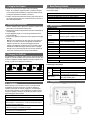
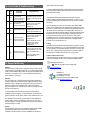
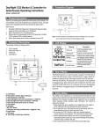
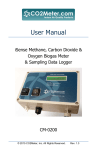
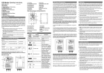
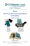
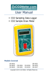
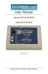
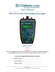
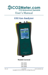
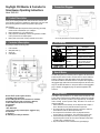
Day/Night CO2 Monitor & Controller for
Greenhouses Operating Instructions
3. Connection Diagram
Model: RAD-0501
1. Product Description
Thank you for selecting the RAD-0501 wall mounted CO2 controller. The
CO2 controller can be used in greenhouses, hydroponics rooms, and other
places where regulated CO2 levels are important for plant growth.
Main Features:
1. Dual Beam NDIR (Non-Dispersive Infrared) technology accurately
measures CO2 concentrations up to 10,000ppm
2. Built-in temperature (C or F) measurement
3. Relay output can automatically control a CO2 generator or bottled
CO2 to produce CO2 in confined spaces
4. Built-in photo sensor turns off relay in darkness to save CO2
Note: The CO2 controller is not designed to control a ventilation fan. It is up to the
user to verify that CO2 does not reach dangerous levels.
2. Contents & Description
4. LCD Display
The package contains the following items:
Symbol
1.
2.
3.
4.
CO2 Controller
Wall panel holder (1)
Screws (6)
User Manual
Meaning
CO2 Level
Description
CO2 Concentration in ppm
(Parts Per Million)
Temperature
displays current temperature
Restore Factory
Settings
Restore factory default settings
and delete all custom settings
Adjust CO2 level when the
accuracy deviates from the
actual CO2 concentration
CO2 level when relay is
activated
Calibration
Set CO2 Value
5. How it Works
The Red LED (power) is on when the power is supplied. The Yellow LED is
lit when the photo sensor is active. The Photo sensor is used to detect the
presence or absence of light. When light is present, and CO2 levels are
lower than the SetPoint, the Green LED is on and power will be supplied to
the piggyback plug. When CO2 levels reach the high level, the Green LED
will go off, the Red LED will turn on, and power will be cut to the piggyback
plug. In darkness, the piggyback plug is not powered regardless of the
CO2 level.
A. LCD Display
B. Photo Sensor (monitor light or darkness)
C. Red LED (power on indicator)
D. Green LED (lights when CO2 concentration is < SetPoint)
E. Red LED (lights when CO2 concentration > SetPoint)
F. Yellow LED (verifies photo sensor is working)
G. Down Button
H. Up Button
I. SEL / ENT Button
J. Unit power and relay-controlled power “piggyback” plug
K. Panel Holder
L. CO2 sensor
M. Tube fitting for bottled gas calibration
6. Safety Notice
Your safety is very important to us. To ensure correct and safe use of the
product, please read this entire User Manual before using the CO2 controller.
Otherwise, the protection provided by the equipment may be impaired.
These warnings provide important safety information and should be
observed at all times.
1. Please handle the device carefully; do not subject the unit to impact or
shock. Otherwise, this may decrease the sensor’s precision.
2. Do not place the unit or the power plug near a heat source. Heat can
cause distortion of the unit, which may result in fire.
3. Do not open the CO2 Controller or touch any exposed electronic
circuitry under any circumstances. This could result in electric shock.
4. Use the attached power adaptor and cord in a grounded plug only.
Ungrounded power sources can cause serious damage to the product,
or result in injury or death to the user.
5. Only connect devices to the controller that use grounded plugs.
7. Caring for the Product
11. Reset Factory Defaults
To get the most out of this product, please observe the following:
Fix improperly set SetPoint or manual calibration problems by restoring the
factory default settings:
1. Repair - Do not attempt to repair the product or modify the circuitry by
yourself. Please contact CO2Meter.com if the product needs servicing,
including the replacement or calibration of the sensor.
2. Cleaning - Disconnect the power before cleaning. Use a damp cloth. Do
not use liquid cleaning agents such as benzene, thinner or aerosols, as
these will damage the device.
8. Installation Instructions
1. Choose a suitable location at plant level to install the controller. Fix the
panel holder on the wall with the included screws.
2. Snap the CO2 Controller on the panel holder and make sure that they are
connected tightly.
3. Plug the piggyback plug into a 110-220 VAC grounded wall socket to
power the controller.
4. Connect a CO2 generator or bottled CO2 control regulator into the piggy
back plug.
Note: The CO2 controller has one relay output. The relay cable is prewired into it. The relay can control a CO2 generator or bottled CO2
regulator to produce CO2. The relay will be triggered and power
supplied on the piggyback plug when the CO2 concentration is below
the SetPoint and when there is light on the photo sensor. If the light
intensity is too low (cannot be set by the user), the CO2 controller will
not be active, even if the CO2 level is less than the SetPoint.
9. Changing the SetPoint
The default SetPoint is 1,000ppm. Under normal use, this means that during
daylight, the controller will attempt to keep the CO2 level in the grow room
as close to 1,000ppm as possible. Depending on the types of plants you are
growing, you may wish to change the CO2 SetPoint.
1. Hold the SEL/ENT button down until the “SetPoint” icon flashes.
2. Press the DOWN button twice. The “ReFactSet” icon will flash.
3. Press the SEL/ENT button The word “No” will be displayed.
4. Press the UP or DOWN button to Select “Yes”.
5. Press the SEL/ENT button to reset factory defaults.
12. Specifications
CO2 Specification
Measurement Range
Display Resolution
Accuracy
Repeatability
Pressure
Dependence
Response Time
SetPoint
SetPoint Hysteresis
Warm-Up Time
0 - 10,000ppm
1ppm at 0~1,000ppm; 10ppm above 1,000ppm
0~2,000ppm: ±70ppm or ±5% of reading,
whichever is greater. >2000ppm: ±7% of reading
±20ppm @400ppm
0.13% of reading per mm Hg
< 2 minutes for 63% response to step change
Default value = 1,000ppm
Default Hysteresis value: 400ppm
< 60 seconds at 22°C
IP54
Splash Rating
Operating Conditions:
Temperature
32°F to 122°F (0°C to 50°C)
Humidity
0 ~ 95% RH non-condensing
Storage Conditions:
Temperature
-4°F to 140°F (-20°C to 60 °C)
Power Supply & Relay Output:
1. Hold the SEL/ENT button down until the “SetPoint” icon flashes.
2. Press SEL/ENT button again to enter SetPoint mode.
3. Press the UP / DOWN buttons to adjust the SetPoint level.
4. Press the SEL/ENT button again. SAVE appears on the LCD
5. Press the UP button to exit SetPoint mode.
10. Calibration
Between growing cycles or at least once a year, you should manually
recalibrate the unit. We recommend you use fresh air (400ppm) for
calibration by taking the unit outdoors, plugging it in, and following the
procedure below. Optionally, you can calibrate using a cylinder of known
CO2 gas (0~2000ppm) connected to the “M” fitting for at least 5 minutes
before following the same procedure.
1. Hold the SEL/ENT button down until the “SetPoint” icon flashes.
2. Press the DOWN button once and the “Cali” icon will flash.
3. Press SEL/ENT button and the “Cali” icon will stop flashing.
4. Press the UP or DOWN buttons to select the CO2 calibration value.
Select 400ppm for outdoor/fresh air, or select the number that matches
the known CO2 gas cylinder rating.
5. Hold the SEL/ENT button until the “Cali” icon flashes again.
Calibration has begun. This will take 3-5 minutes.
6. If the word PASS is displayed, press the SEL/ENT button, then the
UP button twice to exit calibration mode.
7. If the word FAIL is displayed, press SEL/ENT and return to step # 3.
Power Supply
Voltage
AC
Frequency
Input
Power
Requirement
Relay Socket
13. Dimensions
AC adapter 110/220 VAC
100 ~ 240 VAC
50 / 60 Hz
1 W maximum @ 115 VAC 60 Hz
2 W maximum @ 230 VAC 50 Hz
One Relay output, Peak Current < 5A@ 250
VAC, SPST. Normally Open.
14. Error Codes & Troubleshooting
No
1
2
3
4
5
LCD
Fault
Icon
Description
(of the fault)
Suggested Actions
Er3
The ambient temperature
has exceeded the
temperature range 0°C to
50°C ( 32°F to 122°F)
This error will disappear when the
temperature returns to the range
between 0°C and 50°C (32°F to
122°F).
Er4
Inaccurate measurement
or the sensor has
exceeded its expected life
Please unplug the AC adapter and
reconnect it. If the “Er4” always
appears, please contact
CO2Meter.com.
Er5
Er6
Er8
FAIL
Please unplug the AC adapter and
EEPROM System Problem reconnect it. If the “Er5, Er6” still
appears, please CO2Meter.com.
The accuracy of CO2
sensor may deviate from
the actual concentration.
①Please unplug the AC adapter
and reconnect. If the “Er8” still
appears, please contact
CO2Meter.com.
②Please calibrate the unit. After
calibration if the “Er8” still
appears, please contact
CO2Meter.com.
①CO2 level has varied too much
during the calibration cycle. Control
Calibration Fail (FAIL is
the CO2 concentration and try
displayed after calibration). again.
②If FAIL still appears, please
contact CO2Meter.com
replace the item at our discretion.
To obtain an RMA number, please call CO2Meter.com at (385) 256-4910.
When requesting an RMA number, please provide the reason for return
and original order number.
If we determine that the product failed due to improper use (water
damage, dropping, tampering, electrical damage etc.) or abuse, or if it is
beyond the warranty period, we will inform you of the cost to fix or replace
your device.
If you are returning your device due to a warranty claim (with an RMA
number) and you still have the unit original package, please use it to ship
your unit to us. Please make sure to include the provided RMA number on
the outside of the box, preferably on the shipping label. Make sure you
secure the unit inside the package properly to prevent any damage during
transit that could void your device’s warranty. Finally, please ship your
device to the address shown under the “Contact Us” section below.
CO2Meter.com will not, under any circumstances, be responsible for your
shipment expenses and no refund will be issued for shipping charges
necessary for you to ship the unit to us.
Liability
All liabilities under this agreement shall be limited to the actual cost of the
product paid to CO2Meter.com. In no event shall CO2Meter.com be liable
for any incidental or consequential damages, lost profits, loss of time, lost
sales or loss or damage to data, injury to person or personal property or
any other indirect damages as the result of use of our products.
Contact us: We’re here to help!
If the troubleshooting guide above doesn’t help you solving your problem
or for more information, please contact us using the information below.
15. Support & Warranty
[email protected]
(386) 256-4910 (M-F 9:00am–6:00pm EST)
Support
The quickest way to obtain technical support is via email. Please send all
support enquires to [email protected]. In your email, please include
a clear, concise definition of the problem and any relevant troubleshooting
information or steps taken so far, so we can duplicate the problem and
quickly respond to your inquiry.
www.CO2Meter.com
Warranty
This unit comes with a 1 YEAR (warranty period) limited manufacturer’s
warranty, starting from the date the unit was shipped to the buyer. During
this period of time, CO2Meter.com warrants our products to be free from
defects in materials and workmanship when used for their intended
purpose and agrees to fix or replace (at our discretion) any part or product
that fails under normal use.
To take advantage of this warranty, the product must be returned to
CO2Meter.com at your expense. If, after examination, we determine the
product is defective, we will repair or replace it at no additional cost to you.
This warranty does not cover any products that have been subjected to
misuse, neglect, accident, modifications or repairs by you or by a third
party. No employee or reseller of CO2Meter.com’s products may alter this
warranty verbally or in writing.
Returns
If the product fails under normal use during the warranty period, an RMA
(Return Material Authorization) number must be obtained from
CO2Meter.com. After the item is received, CO2Meter.com will repair or
CO2Meter, Inc.
131 Business Center Drive
Ormond Beach, FL 32174
Phone: 386-872-7665 | Fax: 866-422-2356
Email: [email protected]
Ref. No.:062015