1
Preface, Contents
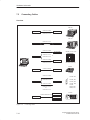
Product Overview
1
Installing the PG 740 PII
2
Starting Up the PG 740 PII
3
PG 740 PII Expansions
4
Configuring the PG 740 PII
5
Error Diagnostics
6
Hardware Information
7
SIMATIC
Programming Device
PG 740 PII
Manual
Appendix
ESD Guidelines
Glossary, Index
01/99
C79000-G7076-C749
Version 02
A
Safety Guidelines
!
!
!
#$. ()0' *)/$). )*/$ . 2#$# 4*0 .#*0' *. -1 /* ).0- 4*0- *2) + -.*)' .! /4 . 2 '' . /*
+-*/ / /# +-*0/ ) *)) / ,0$+( )/ # . )*/$ . - #$"#'$"#/ $) /# ()0' 4 2-)$)"
/-$)"' ) - (-& . !*''*2. *-$)" /* /# ' 1 ' *! )" -
Danger
( ). /#/ /# . 1 - + -.*)' $)%0-4 *- .0./)/$' +-*+ -/4 (" - .0'/ $! +-*+ - +- 0/$*). )*/ /& )
Warning
$)$/ ./#/ /# . 1 - + -.*)' $)%0-4 *- .0./)/$' +-*+ -/4 (" ) - .0'/ $! +-*+ - +- 0/$*). )*/ /& )
Caution
$)$/ . /#/ ($)*- + -.*)' $)%0-4 *- +-*+ -/4 (" ) - .0'/ $! +-*+ - +- 0/$*). - )*/ /& )
Note
-2.4*0- // )/$*) /* +-/$0'-'4 $(+*-/)/ $)!*-(/$*) *) /# +-*0/ #)'$)" /# +-*0/ *- /* +-/$0'+-/ *! /# *0( )//$*)
Qualified Personnel
# 1$ .4./ ( (4 *)'4 . / 0+ ) *+ -/ $) *)%0)/$*) 2$/# /#$. ()0'
)'4 .#*0' ''*2 /* $)./'' ) 2*-& *) /#$. ,0$+( )/ 0'$!$ + -.*). $) /#
. ). *! /# .! /4 "0$ '$) . *! /#$. )0' - !$) . + -.*). 2#* - 0/#*-$5 /* *(($..$*) /*
"-*0) ) /* /" ,0$+( )/ .4./ (. ) $-0$/. $) *-) 2$/# ./'$.# .! /4 +-/$ . )
./)-.
Correct Usage
!
*/ /# !*''*2$)"
Warning
#$. 1$ ) $/. *(+*) )/. (4 *)'4 0. !*- /# ++'$/$*). .-$ $) /# /'*" *- /# / #)$'
.-$+/$*) ) *)'4 $) *)) /$*) 2$/# 1$ . *- *(+*) )/. !-*( */# - ()0!/0- -. 2#$# #1 )
++-*1 *- - *(( ) 4 $ ( ).
#$. +-*0/ ) *)'4 !0)/$*) *-- /'4 ) .! '4 $! $/ $. /-).+*-/ ./*- . / 0+ ) $)./'' *-- /'4 )
*+ -/ ) ($)/$) . - *(( ) Trademarks
R R ) R - - "$./ - /- (-&. *! #$- +-/$ . 0.$)" !*- /# $- *2) +0-+*. . )4 */# - )( . $) /#$. *0( )/ 2#$# - ! - /* /- (-&. ($"#/
$)!-$)" 0+*) /# -$"#/. *! /# /- (-& *2) -.
Copyright E Siemens AG 1998 All rights reserved
Disclaimer of Liability
# - +-*0/$*) /-).($..$*) *- 0. *! /#$. *0( )/ *- $/. *)/ )/. $.
)*/+ -($// 2$/#*0/ 3+- .. 2-$// ) 0/#*-$/4 !! ) -. 2$'' '$' !*(" . '' -$"#/. $)'0$)" -$"#/. - / 4 +/ )/ "-)/ *-- "$./-/$*)
*! 0/$'$/4 (* ' *- .$") - - . -1 #1 # & /# *)/ )/. *! /#$. ()0' !*- "- ( )/ 2$/# /#
#-2- ) .*!/2- .-$ $) 1$/$*). ))*/ +- '0 )/$- '4 2 ))*/ "0-)/ !0'' "- ( )/ *2 1 - /# / $) /#$.
()0'- - 1$ 2 - "0'-'4 ) )4 ) ..-4 *-- /$*). $)'0 $)
.0. ,0 )/ $/$*). 0"" ./$*). !*- $(+-*1 ( )/ - 2 '*( $ ( ). - $# 0/*(/$.$ -0)".7 0) )/-$ ./ #)$&
.# !/." $ / )0./-$ 70/*(/$.$ -0)"..4./ (
*./!# 67
0 -) -"
Siemens Aktiengesellschaft
E Siemens AG 1998
#)$' / .0% / /* #)" C79000-G7076-C749
Preface
What this Manual
is About
This manual contains all the information you need for working with the
PG 740 PII programming device. You can use it to
S unpack the programming device and power it up.
S familiarize yourself with the functions and settings of the various
components (display, keyboard, programming facilities etc.).
S connect the programming device up to other units of equipment
(programmable controllers, other programming devices).
S expand your system, provided you comply with the necessary conditions.
S analyze and eliminate simple faults.
Who is the Manual
Intended For?
The following persons require the manual:
S Users commissioning the programming device themselves or working
with it (editing, programming or debugging).
S System administrators operating the programming device in a network.
S Service and maintenance personnel using the PG 740 PII for system
expansion purposes or error/fault analysis.
Other Manuals
This manual does not contain information on the operating system or
programming software. You will find this information in the relevant
software manuals.
Operating
Instructions
The Operating Instructions supplied with the PG 740 PII contains the latest
technical specifications of the programming device, and the addresses and
telephone numbers of the repair and maintenance centers authorized from
Siemens.
Programming Device PG 740 PII
C79000-G7076-C749-02
iii
Preface
Queries
If you have any questions concerning subjects not covered in the manual, just
get in touch with the Siemens representative in your area.
If you have any questions on the manual itself or would like to make remarks
or suggestions, please complete the reply card at the end of the manual. We
would also appreciate it if you would include your own personal opinion on
the manual on the reply card.
Pointers through
the Manual
The manual contains both the most important instructions for starting up and
using the programming device, as well as reference sections you will only
require in special cases.
Installation
Before you use the PG 740 PII for the first time, read Chapter 2 on the
PG 740 PII’s components and functionality.
Startup
Chapter 3 describes the basic steps necessary for starting up the PG 740 PII.
This section also contains instructions for working with memory cards for
programmable controllers and for connecting the programming device to
other devices.
Expansion
Chapter 4 describes how to expand your PG 740 PII (installation of memory
expansion or additional modules). Please observe the safety notes.
Configuration
Modifications to the system hardware may make it necessary for you to adapt
the original hardware configuration. Chapter 5 tells how to proceed in this
case.
Error/Fault
Diagnostics
Chapter 6 will tell you how to deal with simple faults that you can diagnose
and, in some cases, eliminate yourself.
Reference Data
Chapter 7 contains hardware addresses, interrupt assignments and
information on connecting cables.
Glossary
The glossary explains important terms.
Alphabetical Index
The index will enable you to quickly find passages in the text pertaining to
important keywords.
iv
Programming Device PG 740 PII
C79000-G7076-C749-02
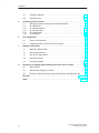
Contents
1
Product Overview . . . . . . . . . . . . . . . . . . . . . . . . . . . . . . . . . . . . . . . . . . . . . . . . . . . . . .
1-1
2
Installing the PG 740 PII . . . . . . . . . . . . . . . . . . . . . . . . . . . . . . . . . . . . . . . . . . . . . . . . .
2-1
2.1
Setting up the PG 740 PII . . . . . . . . . . . . . . . . . . . . . . . . . . . . . . . . . . . . . . . .
2-2
2.2
Hardware Components of the PG 740 PII . . . . . . . . . . . . . . . . . . . . . . . . . . .
2-6
2.3
Display . . . . . . . . . . . . . . . . . . . . . . . . . . . . . . . . . . . . . . . . . . . . . . . . . . . . . . . .
2-10
2.4
Keyboard . . . . . . . . . . . . . . . . . . . . . . . . . . . . . . . . . . . . . . . . . . . . . . . . . . . . . .
2-11
2.5
Trackball . . . . . . . . . . . . . . . . . . . . . . . . . . . . . . . . . . . . . . . . . . . . . . . . . . . . . . .
2-16
2.6
Floppy Disk Drive . . . . . . . . . . . . . . . . . . . . . . . . . . . . . . . . . . . . . . . . . . . . . . .
2-18
2.7
Hard Disk Drive . . . . . . . . . . . . . . . . . . . . . . . . . . . . . . . . . . . . . . . . . . . . . . . . .
2-19
2.8
CD-ROM Drive . . . . . . . . . . . . . . . . . . . . . . . . . . . . . . . . . . . . . . . . . . . . . . . . . .
2-20
2.9
Transport . . . . . . . . . . . . . . . . . . . . . . . . . . . . . . . . . . . . . . . . . . . . . . . . . . . . . . .
2-21
Starting Up the PG 740 PII . . . . . . . . . . . . . . . . . . . . . . . . . . . . . . . . . . . . . . . . . . . . . . .
3-1
3.1
Connecting the PG 740 PII to the Power Supply . . . . . . . . . . . . . . . . . . . . .
3-2
3.2
Connecting I/O Devices . . . . . . . . . . . . . . . . . . . . . . . . . . . . . . . . . . . . . . . . . .
3-3
3.3
Working with SIMATIC S5 Memory Submodules . . . . . . . . . . . . . . . . . . . . .
3-9
3.4
Working with SIMATIC Memory Cards . . . . . . . . . . . . . . . . . . . . . . . . . . . . .
3-10
3.5
Working with Headphones and Microphone . . . . . . . . . . . . . . . . . . . . . . . . .
3-12
3.6
Working with Cardbus/PC Cards . . . . . . . . . . . . . . . . . . . . . . . . . . . . . . . . . .
3-13
3.7
PG 740 PII Connections (Point-to-Point Connections) . . . . . . . . . . . . . . . .
3-14
3.8
Multipoint Interface (MPI/DP) . . . . . . . . . . . . . . . . . . . . . . . . . . . . . . . . . . . . .
3-18
3.9
PROFIBUS (SINEC L2) . . . . . . . . . . . . . . . . . . . . . . . . . . . . . . . . . . . . . . . . . .
3-20
3.10
Industrial Ethernet (SINEC H1) . . . . . . . . . . . . . . . . . . . . . . . . . . . . . . . . . . . .
3-21
PG 740 PII Expansions . . . . . . . . . . . . . . . . . . . . . . . . . . . . . . . . . . . . . . . . . . . . . . . . . .
4-1
4.1
Opening the Unit . . . . . . . . . . . . . . . . . . . . . . . . . . . . . . . . . . . . . . . . . . . . . . . .
4-2
4.2
Functional Units Visible after Opening the Unit . . . . . . . . . . . . . . . . . . . . . .
4-4
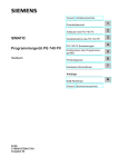
4.3
Block Diagram of the Mother Board . . . . . . . . . . . . . . . . . . . . . . . . . . . . . . . .
4-5
4.4
Installing Expansion Modules . . . . . . . . . . . . . . . . . . . . . . . . . . . . . . . . . . . . .
4-11
4.5
Installing Memory Expansion Cards . . . . . . . . . . . . . . . . . . . . . . . . . . . . . . . .
4-13
4.6
Backup Battery . . . . . . . . . . . . . . . . . . . . . . . . . . . . . . . . . . . . . . . . . . . . . . . . .
4-16
3
4
Programming Device PG 740 PII
C79000-G7076-C749-02
v
Contents
5
4.7
Processor Upgrade . . . . . . . . . . . . . . . . . . . . . . . . . . . . . . . . . . . . . . . . . . . . . .
4-17
4.8
Closing the Unit . . . . . . . . . . . . . . . . . . . . . . . . . . . . . . . . . . . . . . . . . . . . . . . . .
4-17
Configuring the PG 740 PII . . . . . . . . . . . . . . . . . . . . . . . . . . . . . . . . . . . . . . . . . . . . . .
5-1
5.1
5.1.1
5.1.2
5.1.3
5.1.4
5.1.5
6
7
A
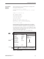
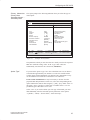
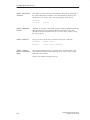
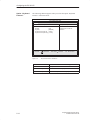
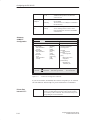
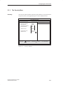
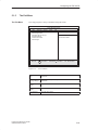
Changing the Device Configuration with BIOS SETUP . . . . . . . . . . . . . . . .
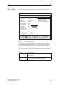
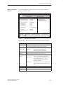
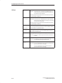
The Main Menu . . . . . . . . . . . . . . . . . . . . . . . . . . . . . . . . . . . . . . . . . . . . . . . . .
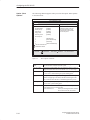
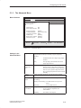
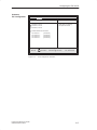
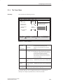
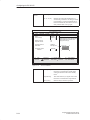
The Advanced Menu . . . . . . . . . . . . . . . . . . . . . . . . . . . . . . . . . . . . . . . . . . . . .
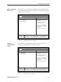
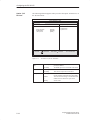
The Security Menu . . . . . . . . . . . . . . . . . . . . . . . . . . . . . . . . . . . . . . . . . . . . . .
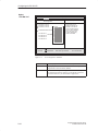
The Power Menu . . . . . . . . . . . . . . . . . . . . . . . . . . . . . . . . . . . . . . . . . . . . . . . .
The Exit Menu . . . . . . . . . . . . . . . . . . . . . . . . . . . . . . . . . . . . . . . . . . . . . . . . . .
5-2
5-5
5-15
5-21
5-23
5-25
Error Diagnostics . . . . . . . . . . . . . . . . . . . . . . . . . . . . . . . . . . . . . . . . . . . . . . . . . . . . . . .
6-1
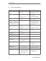
6.1
Faults in PG Operation . . . . . . . . . . . . . . . . . . . . . . . . . . . . . . . . . . . . . . . . . . .
6-2
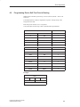
6.2
Programming Device Self-Test Prior to Booting . . . . . . . . . . . . . . . . . . . . . .
6-3
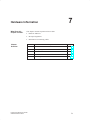
Hardware Information . . . . . . . . . . . . . . . . . . . . . . . . . . . . . . . . . . . . . . . . . . . . . . . . . . .
7-1
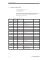
7.1
Hardware Address Table . . . . . . . . . . . . . . . . . . . . . . . . . . . . . . . . . . . . . . . . .
7-2
7.2
Interrupt Assignments . . . . . . . . . . . . . . . . . . . . . . . . . . . . . . . . . . . . . . . . . . . .
7-6
7.3
PG 740 PII Video Modes . . . . . . . . . . . . . . . . . . . . . . . . . . . . . . . . . . . . . . . . .
7-7
7.4
Connector Pinouts . . . . . . . . . . . . . . . . . . . . . . . . . . . . . . . . . . . . . . . . . . . . . . .
7-8
7.5
Connecting Cables . . . . . . . . . . . . . . . . . . . . . . . . . . . . . . . . . . . . . . . . . . . . . .
7-16
Guidelines for Handling Electrostatically-Sensitive Devices (ESD) . . . . . . . . .
A-1
A.1
What is ESD? . . . . . . . . . . . . . . . . . . . . . . . . . . . . . . . . . . . . . . . . . . . . . . . . . . .
A-2
A.2
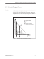
Electrostatic Charging of Persons . . . . . . . . . . . . . . . . . . . . . . . . . . . . . . . . .
A-3
A.3
General Protective Measures Against Electrostatic Discharge Damage .
A-4
Glossary . . . . . . . . . . . . . . . . . . . . . . . . . . . . . . . . . . . . . . . . . . . . . . . . . . . . . . . . . . Glossary-1
Index . . . . . . . . . . . . . . . . . . . . . . . . . . . . . . . . . . . . . . . . . . . . . . . . . . . . . . . . . . . . . . . . Index-1
vi
Programming Device PG 740 PII
C79000-G7076-C749-02
Product Overview
1
Application
The PG 740 PII programming device is a high-performance device, equipped
with the optimum hardware features and software for programming,
debugging, and starting up programmable controllers in an automation
environment.
Hardware/Software
Complement
You can use the PG 740 PII programming device to program SIMATIC S5
and SIMATIC S7 programmable controllers. It has
interface ports for connection to the programmable controllers
programming facilities for S5 and S7 memory cards.
The PG 740 PII is shipped with the software listed in the Operating
Instructions.
Programming Device PG 740 PII
C79000-G7076-C749-02
1-1
Product Overview
Advantages of
the PG 740 PII
Compared to a PC with standard hardware and software, the PG 740 PII
programming device of the SIMATIC family has numerous advantages:
You can develop, debug and document user programs for SIMATIC S5
and SIMATIC S7 programmable logic controllers with the PG 740 PII
without the need for additional hardware or software.
The rugged design and functionality of the PG 740 PII make it
particularly suitable for use on site under hostile industrial conditions.
The PG 740 PII meets the specific requirements of industrial
environments, such as noise immunity, compliance with the relevant
standards, ruggedness, simple transportation, and startup.
The PG 740 PII can be set up and operated in a large number of different
ways and positions, and can therefore be used practically everywhere it is
needed.
The PG 740 PII has all the integral ports necessary for connecting it to
SIMATIC automation devices:
– Programming interface for SIMATIC S5 EPROMs and EEPROMs
– Programming interface for SIMATIC S5 and SIMATIC S7 memory
cards in credit-card format
– Interfaces for connection to S5 and S7 programmable controllers.
The PG 740 PII is supplied with all the necessary system and automation
software already installed on the hard disk.
Since Windows 98 is also already installed, you can, of course, also use
the PG 740 PII as a stand-alone workstation, and run all the standard
software available on the market that requires Windows 98.
The PG 740 PII has the power and expansion capability of normal PCs,
and can therefore also be used as a fully-fledged personal computer.
A PCI slot and a PCI/ISA slot are available for expansions.
The BIOS has the following functions:
– Bootable CD-ROM
– PCI interrupt rooting
– Reserving of ISA interrupts
– The area from 15 to 16 Mbytes can be reserved for the ISA memory
(memory gap)
The mother board has been greatly improved:
– Slot 1 with Pentium II
– Sound interface compatible with a soundblaster.
– Interface for microphone and headphone connections. The PG 740 PII
has two loudspeakers to the left and right of the display which switch
off automatically when headphones are connected.
1-2
Programming Device PG 740 PII
C79000-G7076-C749-02
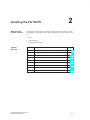
2
Installing the PG 740 PII
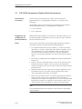
What Does this
Chapter Contain?
This chapter describes how you install your PG 740 PII. It provides you with
comprehensive information on the major components of the PG 740 PII, such
as:
drives
keyboard, and
programming facilities.
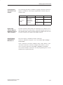
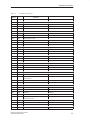
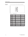
Chapter
Overview
Section
Description
Page
2.1
Setting up the PG 740 PII
2-2
2.2
Hardware Components of the PG 740 PII
2-6
2.3
Display
2-10
2.4
Keyboard
2-11
2.5
Trackball
2-16
2.6
Floppy Disk Drive
2-18
2.7
Hard Disk Drive
2-19
2.8
CD-ROM Drive
2-20
2.9
Transport
2-21
Programming Device PG 740 PII
C79000-G7076-C749-02
2-1
Installing the PG 740 PII
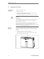
2.1
Setting up the PG 740 PII
Unpacking the
PG 740 PII
Unpack your PG 740 PII as follows:
1. Remove the packing.
2. Do not throw the original packing away. Keep it in case you have to
transport the unit again sometime in the future.
3. Check with the packing list to make sure no components are missing.
!
Caution
Risk of damage
When transporting the unit in cold weather, when it may be submitted to
extreme variations in temperature, make sure that no condensation is
allowed to form on or in the unit.
The unit should be allowed to reach room temperature slowly before it is
started up. If condensation has formed, the unit should be left for
approximately 12 hours (with a temperature difference of -20° C to + 20° C
(-4° F to + 68° F)) before being switched on.
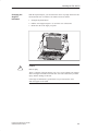
Desk-Top
Mounting
The PG 740 PII is usually mounted on a desk or table top. To make working
with the PG 740 PII easier, it can be adapted as follows to the particular
workplace:
1. Set the PG 740 PII down on the desk or table top.
2. Open the keyboard lock by pulling up the anthracite-colored handle.
3. Swing the keyboard down into position.
Handle
2-2
Programming Device PG 740 PII
C79000-G7076-C749-02
Installing the PG 740 PII
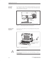
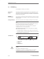
Changing the
Angle of
Inclination
With the keyboard open, you can incline the unit to any angle between 0 and
90° around the axis of rotation of its stand. Proceed as follows:
1. Swing the keyboard down.
2. Pull the extra support (Figure 2-1) out of the rear of the stand.
3. Incline the unit to the angle you prefer.
!
Caution
Risk of injury
There is a danger of the unit tipping over if it is set up without extra support
and at an angle of inclination of more than 15°. This could lead to personal
injury and also damage to the unit.
If the angle of inclination is greater than 15°, you must use the extra
slide-out support in the stand.
Programming Device PG 740 PII
C79000-G7076-C749-02
2-3
Installing the PG 740 PII
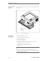
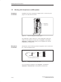
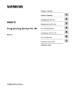
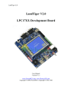
Horizontal
Mounting
If you do not have a desk or table on which to mount the unit, you can work
with it standing on the floor. You can swing the casing with display through
about 90° into the horizontal plane.
Pivot
CD-ROM drive
Stand
Figure 2-1
Detaching the
Keyboard
Extra pull-out support
Horizontal Operating Position without Keyboard
You can remove the keyboard if you are operating the unit in the position
shown in Fig. 2-1.
Press down on the locks in
the middle of the hinge
assembly
Figure 2-2
!
2-4
Detaching the Keyboard
Caution
If the keyboard is detached, there is a risk of the unit falling over. Pull out
the extra support.
Programming Device PG 740 PII
C79000-G7076-C749-02
Installing the PG 740 PII
You detach the keyboard as follows:
1. Grip the keyboard hinges in the stand behind the keyboard.
2. Pull the locks in the middle of the hinge assembly toward the keyboard.
3. Pull the keyboard up and out.
4. Set the keyboard down on a suitable surface, using the hinge assembly as
a stand.
5. Make sure the cable is not pinched or squashed in any way.
6. To attach the keyboard again, snap the keyboard hinges into the matching
receptacles in the stand.
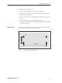
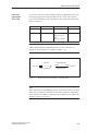
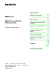
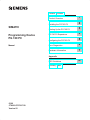
Wall Mounting
The basic unit can be attached to a wall. Four drilled holes (6 mm diameter)
are provided in the base of the unit for this purpose.
83 mm
ø6
345 mm
Figure 2-3
Programming Device PG 740 PII
C79000-G7076-C749-02
Drilling Template for Wall Mounting
2-5
Installing the PG 740 PII
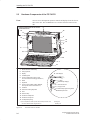
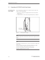
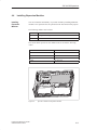
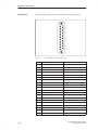
2.2
Hardware Components of the PG 740 PII
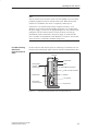
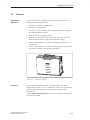
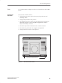
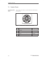
Front
You can access all important operator controls and displays from the front or
sides of the unit. The CD-ROM drive is accessible from the bottom of the
unit.
2
10
10
1
4
16
14
1s
13
3
5
8
11
15
15
6
9
7
12
1
On/off switch for ON/Standby
2
Carrying handle
3
Display
4
Ventilating slots
5
Cover for submodule, memory card,
PC card interfaces and floppy disk drive 1)
6
Stand
7
Keyboard
8
Cover for VGA, COM2, COM1, MPI/DP,
LPT1/printer and mouse interfaces 1)
Hard disk access
9
Trackball
Submodule programming active
10 Catches for locking keyboard
16 LED displays
ON/Standby display 2)
Floppy access
MPI/DP port active
11 Pivot
12 Protector strip
13 Socket for headphones
14 Socket for microphone
15 Loudspeaker opening
1) The coverplates are used to protect the interface ports from dust,
and can be detached and snapped back on.
Figure 2-4
2-6
2) ON: green
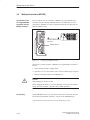
Standby: red
The Front of the PG 740 PII
Programming Device PG 740 PII
C79000-G7076-C749-02
Installing the PG 740 PII
Note
You can use the On/off switch to switch to Power/Standby. You can connect
peripheral equipment to the PG 740 PII in this mode. When the network
connection is withdrawn, the device is completely without power.
If the device was switched off previously using the On/off key or via
Windows, it will remain in Power Standby mode when it is reconnected to
the power supply. If , however, the programming device was switched off by
pulling the network connector from its socket, the device will start up
automatically when reconnected to the power supply. To ensure that the
device switches off automatically when Windows is exited, set “Power OFF
Source Software” to Enabled in the BIOS Setup menu.
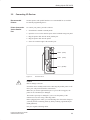
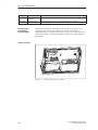
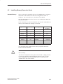
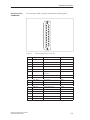
Left Hand Casing
Side Panel
(Communications
Side)
All the connectors and interface ports for connecting to external devices are
located on the left-hand side panel of the PG 740 PII (communications side).
VGA port
On/Off switch
Dummy plates
covering
expansion slots
LEDs
COM 2/V.24 interface
COM 1/V.24/PLC interface
CD-ROM drive
MPI/DP
LPT 1/printer
Power supply
connector socket
Figure 2-5
Programming Device PG 740 PII
C79000-G7076-C749-02
PS/2 mouse
Left-Hand Casing Side Panel with Coverplates Removed
2-7
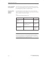
Installing the PG 740 PII
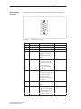
Connectors and
Ports
The following table contains an overview of the various interface ports and
connectors:
Ports and Connectors
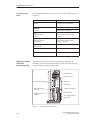
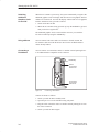
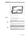
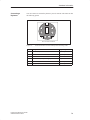
Right-Hand Casing
Side Panel
(Processing Side)
Function
VGA port
Connection for external monitor
COM2
V 24/mouse
V.24/mouse
Serial port
Connection for serial mouse
Connection for serial printer
COM1
V.24/MODEM/PLC
Serial port
Connection for S5 programmable
controller
MPI /DP
(Multipoint interface/
distributed I/Os)
Connection for S7 programmable
controller and for distributed I/Os
(CP5611-compatible)
LPT1 Printer
Parallel interface
Connection for parallel printer
PS/2 mouse
Connection for PS/2 mouse
Connector for power supply
Connection for power supply
You access the slots for S5/S7 memory submodule programming, the
Cardbus/PC card interface and the disk drive from the right-hand side panel
of the PG 740 PII’s casing (processing side).
Ventilating slots
Memory card port
S5 submodule interface
Microphone
Headphones
Ejector for Cardbus
/PC cards
Cardbus/PC card
interface
Ejector for floppy disk
CD-ROM drive
3.5 in. floppy disk drive
Access LED
Figure 2-6
2-8
Right-Hand Casing Side Panel
Programming Device PG 740 PII
C79000-G7076-C749-02
Installing the PG 740 PII
The following table contains an overview of the various interface ports and
connectors:
Interface Port
Ventilating Slots
!
Function
S5 module interface
Programming of SIMATIC S5 memory
submodules
Memory card interface
Programming of SIMATIC memory cards
Cardbus/PC card port
Connection for Cardbus/PC cards
Disk drive
Processing of 3.5 in. disks
The raised air outlet slots for ventilation are located above the interface ports.
There are also ventilating slots on the underside of the base. These slots must
not be covered or blocked in any way (by carpeting, for instance).
Caution
Risk of overheating
If you cover up the slots for the inlet and outlet air in any way, there is a risk
that your PG 740 PII will be damaged.
Do not place any objects over, or lay them on, the ventilating slots.
Programming Device PG 740 PII
C79000-G7076-C749-02
2-9
Installing the PG 740 PII
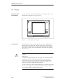
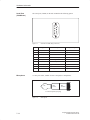
2.3
Display
The PG 740 PII’s
Color Display
The PG 740 PII has a TFT (thin-film transistor) color display with a 13.3 in.
diagonal and a resolution of 1024 x 768 pixels.
SIEMENS
SIMATIC
PG 740 PII
Figure 2-7
Color Shades
!
The PG 740 PII’s Color Display
The three primary colors, red, green and blue, can each be displayed in six
different shades. This means that, including all secondary colors formed, a
maximum of 262144 different colors can be displayed, where the number of
colors can be set in the respective graphic driver The display has automatic
contrast control.
Caution
Risk of injury
If a display is damaged, liquid crystal may escape. Do not touch this liquid
or allow it to come into contact with your skin in any way, and do not
breathe in the vapors. If you do come into contact with the liquid, wash
those parts of the skin affected immediately with alcohol, and rinse with
plenty of water. Then consult a physician right away.
Use only a cotton cloth and a neutral cleansing agent to clean the display. Do
not use water or aggressive solvents (like alcohol or acetone, for instance).
Never touch the display with hard, pointed objects.
2-10
Programming Device PG 740 PII
C79000-G7076-C749-02
Installing the PG 740 PII
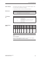
2.4
Keyboard
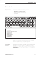
Keyboard Layout
The keyboard is divided into the following three areas:
S Alphanumeric or typewriter keyboard
S Numeric keypad with cursor control keys
S Function keys
1
F1
Esc
~
F2
!
1
F3
@"
2
Q
@
F4
F5
$
4
#w
3
W
5
F6
%
5
E
F7
^&
6
R
T
F8
& /
7{
Y
* (
8[
U
F10
F9
( )
9
I
) =
0 }
O
F11
kkk
__?
Ćß
F12
+
=
{ Ü
[
P
Print
SysRq
} *
~
] +
Pause
Break
6
7
Num
Home
Num
Page
7
Home
Scroll
..
8
9
Page
4
5
6
1
End
2
+
Caps
Lock
A
>
<
Ctrl
S
ZY
Fn
D
X
F
C
G
V
H
B
Alt
J
N
K
Mm
<;
,
>:
.
AltGr
Function keys
6
Upper case active
7
Scroll lock active
| '
\ #
Page
?
Insert
End
3
Page
0
Delete
. ,
Del
Ins
3
2
1
2
3
4
5
" Ä
: Ö
;
L
Enter
4
Typewriter or alphanumeric keyboard
Cursor control keys
Numeric keypad
Numeric block active
Figure 2-8
Keyboard
All keys on the keyboard are of the autorepeat type. That is, the relevant
character is repeated as long as you keep the key pressed.
Setting Up the
Keyboard
When the keyboard is attached to the casing, it has an inclination of 6°, and
the middle row of keys is at a height of 30 mm. When the keyboard is
detached from the casing, its angle of inclination is 4.5° and the middle row
of keys is at a height of 27 mm. Ergonomically, these are the ideal positions
for the keyboard.
Programming Device PG 740 PII
C79000-G7076-C749-02
2-11
Installing the PG 740 PII
Typewriter or
Alphanumeric
Keyboard
The largest block of keys on the keyboard is the alphanumeric or typewriter
keyboard with all the keys for the letters of the alphabet, numerals, and
special characters. The characters (letters, numerals, and special characters)
are arranged in generally the same way as on a normal typewriter. However,
there are a number of special keys which have specific special functions for
the PG 740.
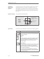
Keyboard Labeling
The keyboard has international labeling.
International
National
Font size and thickness
reduced
Shift
Unshift
Figure 2-9
Special Keys
Example: German
Together with the
ALTGR key
The Keyboard Labeling System
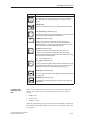
The special keys in the alphanumeric keyboard have the following functions:
Key
Function
Backspace Key
This key moves the cursor one space to the left and deletes the
character at this position
Return Key
(Enter)
The Return or Enter key is used mainly to terminate a command
line in the operating system; that is, the command you have
typed in is executed when you press this key. For other uses of
this key, please refer to the user manual of the relevant
application program.
CAPS-LOCK Key
If you press this key, the middle LED at the top right-hand corner
of your keyboard lights up. All letters then appear in upper case
and the upper of the two characters on the individual keys
applies. If you wish to type in lower-case letters in this position,
you must first strike the Shift key.
If you are using an international keyboard, you cancel this
function by pressing the CAPS-LOCK key again. The LED goes
out. If you have a German keyboard, you must strike the Shift
key to cancel this function.
2-12
Programming Device PG 740 PII
C79000-G7076-C749-02
Installing the PG 740 PII
Key
Function
NUM Key
You switch from the numeric block to cursor control with this key
(Num LED lights up). Press the key again to return to cursor
control.
Tabulator Key
This key moves the cursor by one or more positions to the right.
“Fn” Special key (combination key)
Together with a second key (key combination), you activate other
key codes for specific applications with this key.
CTRL Key (combination key)
This key is only used in combination with other keys. For
example, you press Ctrl + ALT + DEL to reset and restart the
operating system. For other uses of this key, please refer to the
user manual of the relevant application program.
ALT Key (combination key)
This key is only used in combination with other keys. For
instance, you can enter the hexadecimal value of an ASCII
character (and consequently additional special characters) using
this key and the numeric keypad.
ALT + 123 corresponds to ”{”.
ALTGr Key (combination key)
Location and
Labeling of the
LED
You can use this key together with the other combination keys to
generate other key codes. For example, you can generate the ”\”
character on the German keyboard by striking ALTGr + ß.
PRINT Key (combination key)
You can output the current screen display to a printer by pressing
the PRINT key.
PAUSE Key (combination key)
The PAUSE key interrupts program execution in the majority of
applications.
There are three LEDs on the keyboard. They are located to the right of the
function keys in the top row of the keyboard directly above the numeric
keypad.
NUM LOCK
CAPS LOCK
SCROLL LOCK
When the programming device is powered up, the NUM LOCK, CAPS LOCK,
and SCROLL LOCK LEDs light up briefly twice. The keyboard is then ready
for operation.
Programming Device PG 740 PII
C79000-G7076-C749-02
2-13
Installing the PG 740 PII
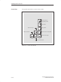
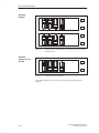
Cursor Keys
The keyblock shown below is used for cursor control.
Move cursor up
Move cursor left
Move cursor to
beginning of file
Page back
Page down
Move cursor to end of file
Move cursor right
Move cursor down
Figure 2-10
2-14
Cursor Control Keypad
Programming Device PG 740 PII
C79000-G7076-C749-02
Installing the PG 740 PII
Key Combinations
The various key combinations are shown in Table 2-1.
Table 2-1
Key Combinations
Function
Key Combination
+
+
+
Warm restart
Switch to international
character set
+
+
LEDs
+
Switch to German character
set; the German character set
must have already been
loaded.
By pressing the Fn key and a
cursor control key in the
numeric keypad
simultaneously, you can
change over to the cursor
control functions of the key.
Trackballactive/passive
The LEDs for the NUM LOCK, CAPS LOCK, and SCROLL LOCK keys are
located at the top right of the keyboard, and indicate the current status of
these keys.
Programming Device PG 740 PII
C79000-G7076-C749-02
2-15
Installing the PG 740 PII
2.5
Trackball
Trackball
The trackball serves as an input device for cursor control and menu selection
in many programs (with mouse operation). By moving the trackball, the
cursor can be repositioned on the screen.
By pressing the left-hand button, you set a marker. The right-hand button is
assigned differently according to the application. You can select objects or
items in a menu, and start functions with the trackball.
Cleaning the
Trackball
The trackball runs in a self-cleaning roller housing which is capable, under
normal conditions, of preventing dust collecting on the trackball and transfer
mechanism. However, you should clean the trackball from time to time.
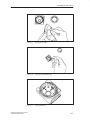
Proceed as follows:
1. Switch off your programming device.
2. Remove the cover of the trackball housing by turning it counterclockwise;
for example, by inserting tweezers or a similar gadget in the holes in the
ring.
3. You can now lift the trackball out of its housing.
4. Wash the trackball with tap water to which a mild cleansing agent has
been added (Figure 2-11).
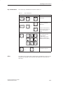
5. Clean the trackball housing (Figure 2-12).
6. Clean the rollers (Figure 2-13).
7. Dry the trackball and return it to its housing.
8. Replace the cover and tighten it by screwing it clockwise.
2-16
Programming Device PG 740 PII
C79000-G7076-C749-02
Installing the PG 740 PII
Figure 2-11
Cleaning the Trackball
Figure 2-12
Cleaning the Trackball Housing
Figure 2-13
Cleaning the Rollers
Programming Device PG 740 PII
C79000-G7076-C749-02
2-17
Installing the PG 740 PII
2.6
Floppy Disk Drive
Memory Capacity
The PG 740 PII is equipped as standard with a 3.5” diskette drive and a
3.5” hard disk drive. You can store programs and data on diskettes with the
diskette drive and load them from diskettes into the PG 740 PII.
Types of Diskette
You can use the following diskettes:
Double-Sided High-Density Diskette
Handling Diskettes
Double-Sided Double-Density Diskette
3.5 in.
3.5 in.
1.44 MB (135 TPI)
720 KB
Programming device recognizes diskettes
by their coding
Programming device recognizes diskettes
by their coding
The diskette is inserted in the diskette drive as shown below:
Ejector
Access LED
!
Caution
Risk of data loss
You must not remove the diskette as long as the access LED is lit.
Otherwise, you may lose the data on the diskette.
Do not remove the diskette until the access LED on the drive or on the front
of the PG 740 PII has gone out.
2-18
Programming Device PG 740 PII
C79000-G7076-C749-02
Installing the PG 740 PII
2.7
Hard Disk Drive
Memory Capacity
You can use a number of different hard disk drives in your PG 740 PII. The
memory capacity of the particular type of hard disk can be found in the
Product Information Bulletin.
Self-Test
Every time the PG 740 PII is switched on or reset, the hard disk drive
performs a self-test, which is repeated during operation.
Whenever the hard disk drive is accessed, the access LED on the front of the
unit lights up.
!
Caution
Risk of data loss and damage to drive
Drives are sensitive to vibrations and shock. Any vibrations occurring during
operation can lead to the loss of data or damage to the drive.
If you intend transporting the unit, switch it off, and wait until the drive has
come to rest (about 20 seconds) before you move it.
Programming Device PG 740 PII
C79000-G7076-C749-02
2-19
Installing the PG 740 PII
2.8
CD-ROM Drive
The CD-ROM drive enables you to read CDs.
Opening the
Drawer
Swing the PG 740 PII into a horizontal position. The CD-ROM drive is now
on the underside of the programming device. Switch on the PG. By briefly
pressing the eject button, the drawer springs out slightly. Now pull the drawer
out until it clicks into position.
Inserting /
Removing CDs
Now insert the CD in the drawer with the labeling face up, and press it firmly
down into the center of the turntable. To remove the CD, hold it by the edges
and pull upwards.
Closing the Drawer
Push in the drawer until it closes completely. Do not press the eject button.
Note
To avoid too much pressure on the open drawer, always hold the drawer at
the front with one hand when inserting or removing a CD.
The EJECT function offered by various applications for opening the
CD-ROM drawer does not work with this drive.
After the drawer has been closed, the CD is tested and the access display
light on the drive starts to flash:
– If the display flashes continually, the CD is faulty but can still be read,
– If the display flashes several times and then remains lit, the CD you have
inserted is defective and cannot be read.
CD-ROM Front
2
1
2
3
4
!
1
3
4
Access display
Drawer
Eject button
Emergency eject
Caution
Risk of data loss and damage to the drive!
CD-ROM drives are sensitive to vibrations and shock. Any vibrations
occuring during operation can lead to damage to the drive or CD.
2-20
Programming Device PG 740 PII
C79000-G7076-C749-02
Installing the PG 740 PII
2.9
Transport
Preparatory
Measures
The PG 740 PII is easy to transport. Before transporting it, however, you
should take the following measures:
1. Switch the PG 740 PII to standby mode.
2. Unplug all connecting cables.
3. Close the covers protecting the ports and connections on the right-hand
and left-hand casing side panels.
4. Bring the unit into an upright position.
5. Swing the keyboard up and press it against the front plate of the unit.
Make sure that the latches on the left and right sides snap in.
6. Use the carrying handle if you only intend transporting the unit over a
short distance.
7. If you are transporting the PG 740 PII over large distances, pack the unit
with all its accessories in the carrying bag supplied.
Figure 2-14
Transport
Prepared for Transport
Despite the fact that the PG 740 PII is of rugged design, its internal
components are sensitive to severe vibrations or impact. You must therefore
protect your PG 740 PII against severe mechanical stressing when
transporting it.
Use the original packing material if you have to ship the PG 740 PII from
one location to another.
Programming Device PG 740 PII
C79000-G7076-C749-02
2-21
Installing the PG 740 PII
!
Caution
Risk of mechanical damage
Moisture or condensation in the unit can result in defects.
When transporting your PG 740 PII in cold weather when it may be exposed
to extreme variations in temperature, make sure that no moisture or
condensation can form on or in the unit.
The unit should be allowed to reach room temperature slowly before it is
started up. If condensation has formed, the unit should be left for about 12
hours (with a temperature difference of -20° C to +20° C (-4° F to +68° F))
before being switched on.
2-22
Programming Device PG 740 PII
C79000-G7076-C749-02
3
Starting Up the PG 740 PII
What does this
Chapter Contain?
This chapter describes what you have to do to set up your PG 740 PII
successfully for operation. This includes
the basic steps for starting up your PG 740 PII
working with memory submodules and cards for the programmable
controllers
connecting your PG 740 PII to other devices.
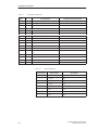
Chapter
Overview
Section
Description
Page
3.1
Connecting the PG 740 PII to the Power Supply
3-2
3.2
Connecting I/O Devices
3-3
3.3
Working with SIMATIC S5 Memory Submodules
3-9
3.4
Working with SIMATIC Memory Cards
3-10
3.5
Working with Headphones and Microphone
3-12
3.6
Working with PCMCIA Cards
3-13
3.7
PG 740 PII Connections (Point-To-Point Connections)
3-14
3.8
Multipoint Interface (MPI/DP)
3-18
3.9
PROFIBUS (SINEC L2)
3-20
3.10
Industrial Ethernet (SINEC H1)
3-21
Programming Device PG 740 PII
C79000-G7076-C749-02
3-1
Starting Up the PG 740 PII
3.1
Connecting the PG 740 PII to the Power Supply
Connecting to the
Power Supply
You can operate the PG 740 PII on 115 V and 230 V power systems. The
voltage is selected automatically.
1. Plug the power supply cable supplied with the unit into the connector
labeled ”Power”.
2. Connect the unit to a socket outlet with grounded protective conductor.
Power supply
connector socket
Figure 3-1
Connecting the Power Supply
Note
The power plug must be disconnected to isolate the unit completely from the
supply.
Note
For operation in Canada and the US, a CSA or UL listed power supply cable
must be used.
The unit is intended for operation with normal grounded power supply
networks (TN networks, VDE 0100 part 300 or IEC 364-3).
The unit is not intended for operation with non-grounded or
impedance-grounded systems (IT systems).
3-2
Programming Device PG 740 PII
C79000-G7076-C749-02
Starting Up the PG 740 PII
3.2
Connecting I/O Devices
Recommended
Printers
Siemens printers with parallel interface are recommended for use with the
PG 740 PII programming device.
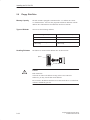
Printer Connection
Via the Parallel
Port
To connect your printer, proceed as follows:
1. Switch the PG 740 PII to standby mode.
2. Open the cover over the interface ports on the left-hand casing side panel.
3. Plug the printer cable into the LPT1 parallel port.
4. Plug the printer cable into the printer.
5. Screw the connector tight at the interface port.
COM 2 (serial)
COM 1 (serial)
LPT 1 (parallel)
Figure 3-2
!
The Printer Ports
Caution
Risk of damage to the unit
Switch the unit to standby mode before connecting the parallel printer to the
LPT1 port. (The printer should be switched off.)
Make sure you use the right interface port. If you use the wrong port, the
printer or PG 740 PII may be damaged.
The interface port may be damaged if you reverse the polarity of the
connections or use the wrong connecting cables.
Before plugging in the cables, you must discharge the electrostatic charge in
your body and the connecting cables by briefly touching a grounded object
(ESD guidelines).
Only use original connecting cables.
Programming Device PG 740 PII
C79000-G7076-C749-02
3-3
Starting Up the PG 740 PII
Printer Connection
Via a Serial Port
You can also connect your printer to the PG 740 PII through a serial COM
port. You will find information on how to adapt and set your interface and on
the connecting cable you require in your printer manual.
Rerouting Printer
Outputs in
MS-DOS
The standard interface for printer output is LPT1. You can reroute printer
outputs to another interface port (COM2). The following table lists examples
of how to change over the interface with the
Mode
command of the MS-DOS operating system:
Interface
Command
Effect
Reroute LPT1 parallel
interface to
COM2/V24/V28 serial
interface
C:MODE LPT1:=COM2
Printer is assigned
to communication
port 2
Configure COM2 for
printer
C:MODE COM2:96,n, 8,1,p
Mode:9600 bps, no parity,
8 databits, 1 stopbit
COM2 is
initialized for
printer
Switch LPT1 interface back C:MODE LPT1:
to parallel interface
The LPT1 is
switched back to
the parallel
interface
Note
To prevent your having to type in the command sequence every time you
restart or reset the hardware, you are advised to store the command sequence
in your AUTOEXEC.BAT file or another BATCH file.
3-4
Programming Device PG 740 PII
C79000-G7076-C749-02
Starting Up the PG 740 PII
Recommended
Monitors
You connect external multisynchronous monitors to the right-hand casing
side panel with the standard VGA connector. We recommend you use
Siemens monitors.
Connecting
Monitors
You must switch the PG 740 PII to standby mode before connecting the
monitor cable. You will find more details in the connector pinout in
Chapter 7.
Monitor socket connector
Figure 3-3
Connecting the Monitor
Connect the monitor as follows:
1. Switch the PG 740 PII to standby mode and switch off the monitor.
2. Open the port cover on the left-hand casing side panel.
3. Plug the monitor cable into the VGA socket connector.
4. Plug the other end of the monitor cable into the monitor.
5. Adjust the monitor settings with the SETUP program.
Additional
Graphics Card
You can plug an additional graphics card into one of the two ISA slots for
special applications.
Connecting
Monitors to
Additional
Graphics Cards
Proceed as follows:
1. Switch the PG 740 PII to standby mode and switch off the monitor.
2. Open the cover for the expansion module connectors on the left-hand
casing side panel.
3. Plug the monitor cable into the VGA socket of the graphics card.
4. Connect the monitor cable to the monitor.
5. Adjust the monitor settings with the SETUP program.
Programming Device PG 740 PII
C79000-G7076-C749-02
3-5
Starting Up the PG 740 PII
Switching
Additional
Graphics Cards
On and Off
When the PG 740 PII is powered up, the system automatically recognizes the
additional graphics card. The display and the built-in VGA graphics interface
module are switched off. To switch the display and the built-in VGA graphics
interface module back on, proceed as follows:
1. Switch on the PG 740 PII.
2. While the PG 740 PII is being powered up, keep the INSERT key pressed
until you hear two signal tones.
The additional graphics card is reactivated the next time you switch the
PG 740 on without pressing the INSERT key.
Using a Mouse
You can connect both a PS/2 and a serial mouse to the PG 740 PII. The
PG 740 PII is delivered with the mouse driver for the trackball and PS/2
mouse already loaded.
Connecting a
PS/2 Mouse
You can connect an external PS/2 mouse or another external pointing device
to an additional PS/2-compatible mouse connector.
ON/Standby
COM 2
Connector for
serial mouse
Connector for
PS/2 mouse
Figure 3-4
Connecting a PS/2 Mouse
Connect the mouse as follows:
1. Switch your PG 740 PII to standby mode.
2. Open the port cover on the left-hand casing side panel.
3. Plug the cable of the PS/2 mouse or another external pointing device into
the mouse connector.
4. Switch your PG 740 PII on again.
3-6
Programming Device PG 740 PII
C79000-G7076-C749-02
Starting Up the PG 740 PII
Switching between
Internal Trackball
and PS/2 Mouse
Once you have plugged in the external mouse and restarted your PG 740 PII,
the internal trackball is inactive, and remains inactive until the PG 740 PII is
powered up again without the external mouse.
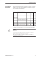
Table 3-1
Trackball/External Mouse Mode
Situation
Connecting a
Serial Mouse
Internal Trackball
No mouse
Active
External mouse
Passive
External PS/2 Mouse
Active
You can connect a serial mouse to the COM2 serial port. To operate a serial
mouse, you must assign the relevant parameters to the mouse driver. You will
find the information you need to do this in the description of your mouse or
in the description of the operating system.
Proceed as follows:
1. Switch your PG 740 PII to standby mode.
2. Open the cover of the interface ports on the left-hand casing side panel.
3. Plug the PS/2 mouse cable or the cable for another external pointing
device into the mouse socket.
4. Switch your PG 740 PII on again.
Programming Device PG 740 PII
C79000-G7076-C749-02
3-7
Starting Up the PG 740 PII
Choosing Another
Keyboard
You can connect another PS/2 keyboard to the PG 740 PII instead of the one
supplied with it.
2
3
1
Extra pull-out support
2
Coverplate
3
Keyboard cable
Figure 3-5
Connecting a
PS/2 Keyboard
1
Connecting a PS/2 Keyboard
You connect the keyboard as follows:
1. Switch your PG 740 PII to standby mode.
2. Pull out the extra support.
3. Turn the casing through 90°.
4. Open the cover on the underside of the unit, using a screwdriver.
5. Unplug the keyboard connector and cable.
6. Plug in the PS/2 keyboard connector and cable.
7. Close the cover.
Note
It is advisable to use a keyboard cable with angled connector. If the
connector is straight, you will not be able to close the cover and this will
restrict the swivel range of the unit.
3-8
Programming Device PG 740 PII
C79000-G7076-C749-02
Starting Up the PG 740 PII
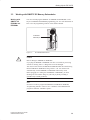
3.3
Working with SIMATIC S5 Memory Submodules
Working with
SIMATIC S5
EPROMs and
EEPROMs
You can read and program SIMATIC S5 EPROMs and EEPROMs via the
48-pin S5 EPROM and EEPROM programming port. You will find details on
how to use the programming software in the STEP 5 Manual.
S5 EPROM/
EEPROM port
Figure 3-6
!
S5 EPROM/EEPROM Port
Caution
Risk of damage to EPROMs or EEPROMs
If you plug the EPROM or EEPROM in or take it out while its processing
software is running, there is a danger that it will be damaged.
You must not take out the S5 EPROM or EEPROM while the LED showing
that the EPROM or EEPROM is being read etc. is lit. You cannot work
simultaneously with S5 EPROMs or EEPROMs and memory cards.
Before plugging in or taking out S5 EPROMs or EEPROMs, you must
discharge the electrostatic charge of your body by briefly touching a
grounded object (ESD guidelines).
Note
In order to be able to program the SIMATIC S5 EPROM or EEPROM,
“Programming Interface” must be set to “Enabled” in the BIOS-SETUP
program in submenu “Hardware Option”.
Programming Device PG 740 PII
C79000-G7076-C749-02
3-9
Starting Up the PG 740 PII
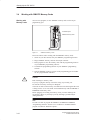
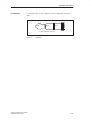
3.4
Working with SIMATIC Memory Cards
Working with
Memory Cards
You can read, program, or erase SIMATIC memory cards via the 68-pin
programming port.
Orientation point
SIMATIC memory cards
Figure 3-7
SIMATIC Memory Cards
Proceed as follows when working with the SIMATIC memory cards:
1. Switch on your PG 740 PII, start your SIMATIC programming function.
2. Plug a SIMATIC memory card into the 68-pin connector.
3. Read, program or erase the memory card with the programming function
of your SIMATIC programming software.
4. Terminate the programming function of your SIMATIC programming
software.
5. Take the SIMATIC memory card out of the programming port for further
use in a programmable controller.
!
Caution
Risk of damage to memory cards
If you try to plug the memory card in the wrong way around, your
PG 740 PII or memory card may be damaged!
You must not take out the memory card while the LED showing that the card
is being read etc. is lit. You cannot work simultaneously with S5 EPROMs or
EEPROMs and memory cards.
Before plugging in or taking out memory cards, you must discharge the
electrostatic charge of your body by briefly touching a grounded object
(ESD guidelines).
Note
In order to be able to program the SIMATIC S5 EPROM or EEPROM,
“Programming Interface” must be set to “Enabled” in the BIOS-SETUP
program in submenu “Hardware Option”.
3-10
Programming Device PG 740 PII
C79000-G7076-C749-02
Starting Up the PG 740 PII
Installing ISA and
PCMCIA Cards
Note the following when installing these cards:
Note
Depending on the configuration of the PG740 PII, there may not be any free
interrupts available for operating ISA/PCMCIA modules. In this case, you must
reserve interrupts in the setup.
To reserve the interrupts, proceed as follows:
In the BIOS setup menu “Advanced,” set the interrupt required by the PCMCIA
or ISA module to “reserved” for “PCI/PNP ISA IRQ Resource Exclusion” in
the line “PCI Configuration” (the default setting is “available”).
Programming Device PG 740 PII
C79000-G7076-C749-02
3-11
Starting Up the PG 740 PII
3.5
Working with Headphones and Microphone
Headphone
Connection
Headphones and active loudspeakers equipped with a 3.5-mm stereo jack
plug can be connected to the socket.
Microphone
Headphones
Figure 3-8
Sockets for Headphones and Microphone
The loudspeaker volume control is set via the loudspeaker button in the
taskbar or in the Windows 98 Start menu via Programs > Accessories >
Multimedia > Volume Control. When you use headphones, the internal
loudspeakers are switched off.
Microphone
Connection
Microphones with the following connector assignments can be connected to
the 3.5-mm microphone socket.
Left
Right
GND
3.5-mm loudspeaker jack plug
Figure 3-9
Assignments of the Microphone Jack
To record using the microphone, select Programs > Accessories >
Multimedia > Sound Recorder in the Windows 98 Start menu.
3-12
Programming Device PG 740 PII
C79000-G7076-C749-02
Starting Up the PG 740 PII
3.6
Working with Cardbus/PC Cards
Cardbus/PC Cards
The PG 740 PII has a PC card port of type II. You can plug communications
cards for MODEM, FAX-MODEM, ISDN, token ring, Ethernet, memory
expansion, and SCSI interface cards in credit-card format into this port.
Ejector for
Cardbus/PC card port
Cardbus/PC card port
Figure 3-10
!
Cardbus/PC Card Port
Caution
Risk of damage
You must insert the Cardbus/PC card with the front side pointing to the rear
of your PG 740 PII. This side generally bears a company or product
designation and the wording “This side up” or a similar labeling.
If you try to insert the Cardbus/PC card the wrong way around, your
PG 740 PII and the Cardbus/PC card may be damaged.
Before plugging in or taking out memory cards, you must discharge the
electrostatic charge of your body by briefly touching a grounded object
(ESD guidelines).
Note
In order to use the Cardbus/PC card, “Cardbus/PCMCIA Slot” must be set to
“Enabled” in the BIOS-SETUP program in menu “Main”, submenu
“Hardware Option”.
Programming Device PG 740 PII
C79000-G7076-C749-02
3-13
Starting Up the PG 740 PII
3.7
PG 740 PII Connections (Point-to-Point Connections)
Point-to-Point
Connection
In this section, you will learn how to connect your PG 740 PII to a
programming device or programmable controller over a point-to-point
connection.
You establish a point-to-point connection by connecting the PG 740 PII to
another programming device or a programmable controller via
a V.24 connection
a TTY connection
Suggestions for
Configuring TTY
(20 mA) Interfaces
Reliable data transfer depends on several factors. The data transfer rate you
can achieve depends on the distance, the type of cable, the type of interface,
and any interference present.
Rules
You can reduce interference by choosing the right transmission cable and
connecting it properly, and observing the following guidelines.
Use a shielded cable with a low line resistance (< 130 W / km) and low
capacitance (< 90 pF/m). Twisted-pair cables enhance immunity to noise
due to inductance. A low surge impedance results in reduced voltage
excursions and shorter charge reversal times. The surge impedance
decreases with increasing conductor cross-section for the same length of
cable.
The shorter the transmission link, the higher the maximum possible data
transfer rate.
If there is an active sender and an active receiver at the same end of the
transmission link, the sequence of access priority to the transmission
circuit must be taken into account in order to achieve the longest possible
transmission link.
Signal lines and power lines must not be run together. Signal lines must
be installed as far away as possible from strong interference sources
(400 V three-phase power cables, for example).
The active TTY interface with 12 V no-load voltage has been tested on a
1000 m (3300 ft.) long cable at a transmission rate of 9600 bps in a
normal noisy environment. If a shielded LiYCY 5x1x0.14 is used, reliable
transmission is possible over a distance of up to 1000 m (3300 ft.). The
AS511 protocol (only one transmitter at a time) was used for testing.
Note
The contaminating field of the interference source decreases exponentially
with the distance.
3-14
Programming Device PG 740 PII
C79000-G7076-C749-02
Starting Up the PG 740 PII
PG to PG
Connection
(TTY, V.24)
If you want to connect your PG 740 PII to another programming device, you
can plug the appropriate connecting cable into the V.24 or TTY interface
port. You will find the necessary information on the connecting cables listed
below in Chapter 7.
Interface
Link
Connecting Cable
V.24 interface
PG 7xx with PG 7xx
6ES5 733-5BD20
TTY interface
PG 7xx with PG 6xx
Series connection of
6ES5 733-2xxx0
and
6ES5 731-6AG001)
Adapter
6ES5 731-6AG00
Note
1)When
connecting the programming devices in series, make sure you
connect the cable the right way around (see Figure 3-11).
Adapter
PG 7XX
6ES5 731-6AG00
Figure 3-11
Connecting cable
Active
Passive
PG 6XX
6ES5 733-2xxx0
Direction of Connection: Adapter - Connecting Cable
Note
When connecting two programming devices via the TTY interface, you must
deactivate one of the TTY interfaces in the circuit (COM1) by changing the
switch position (see Chapter 4). When the PG 740 PII leaves the factory, this
interface is always set to active.
Programming Device PG 740 PII
C79000-G7076-C749-02
3-15
Starting Up the PG 740 PII
Connecting the
PG 740 to S5
Programmable
Controllers
You can connect the PG 740 PII to a SIMATIC S5 programmable controller
via the COM1/TTY interface port. The cable for establishing the connection
to the SIMATIC S5 CPUs is included with the PG 740 PII (order no.
6ES5734-2BF00).
COM 1
Figure 3-12
Connecting the PG 740 PII to an S5 Programmable Controller
You connect your PG 740 PII to a SIMATIC S5 programmable controller as
follows:
1. Switch the PG 740 PII to standby mode.
2. Open the cover over the interface ports on the left-hand casing side panel.
3. Plug the cable into the COM1/V.24 modem/PLC interface port.
!
Caution
Risk of damage to the PG 740 PII
The interface port may be damaged if you confuse the connections or use the
wrong connecting cables. Make sure the TTY cable of the PG 740 PII is
plugged into the COM1/TTY port and not into the LPT1 port.
Before plugging the cables in, you must discharge your body’s electrostatic
charge by briefly touching a grounded object (ESD guidelines).
Use only original cables to establish the connection to the programmable
controller.
3-16
Programming Device PG 740 PII
C79000-G7076-C749-02
Starting Up the PG 740 PII
Connecting the
PG 740 PII via an
Adapter
The connecting cable 6ES5 734-2BD20 is supplied with the PG 740 PII. An
adapter is available for connecting the programmable controller using old
standard cables.
Interface
Link
Connecting Cable
Adapter
6ES5 734-2BD20
TTY interface
(COM1)
PG 740 PII to
SIMATIC S5
programmable
controller
6ES5 731-1xxx0
15-pin
6ES5 731-6AG00
6ES5 731-0xxx0
25-pin
6ES5 731-6AG00
Higher Data
Transfer Rates at
Distances of up to
1000 m (3300 ft.)
In order to maintain a data transfer rate of 9600 bps up to a distance of over
1000 m (3300 ft), the receiving diode is connected to ground (reference) via
the connecting cable. Cables of various lengths are available under the order
no. 6ES5 734-2xxx0 (xxx stands for the length in metres).
Point-To-Point
Connection in
Windows 9x
Proceed as follows to establish an interface connection:
Select the “Add/Remove Programs” icon via the taskbar Start > Settings >
Control Panel.
Select “Connection” in the menu “Windows Setup.” Under “Details,” select
“PC Direct Connection.” Once these settings become effective, you can
select “PC Direct Connection” under Start > Programs > Accessories.
You can then establish a connection to the other programming device via the
standard serial or parallel data lines.
Programming Device PG 740 PII
C79000-G7076-C749-02
3-17
Starting Up the PG 740 PII
3.8
Multipoint Interface (MPI/DP)
Connection of an
S7 Programmable
Controller via the
MPI/DP Interface
You can connect your PG 740 PII to a SIMATIC S7 programmable logic
controller using the floating* MPI/DP interface. The MPI cable (5 m) for
connection to SIMATIC S7 CPUs is supplied with the PG 740 PII (order no.
6ES7901-0BF00-0AA0).
6ES7901-0BF00-0AA0
MPI cable
MPI/DP interface
Figure 3-13
Connecting via MPI/DP Interface
You connect your PG 740 PII to a SIMATIC S7 programmable controller as
follows:
1. Switch the PG 740 PII to standby mode.
2. Open the cover over the interface ports on the left-hand casing side panel.
3. Plug the connecting cable into the MPI/DP port.
!
Caution
Risk of damage to the PG 740 PII
Before plugging the cables in, you must discharge your body’s electrostatic
charge by briefly touching a grounded object (ESD guidelines).
Connecting
Via the MPI/DP interface, you can connect your PGs to the S7-200, S7-300,
and S7-400 programmable controllers, and also to the PROFIBUS DP.
*) Electrical isolation within the safety extra-low voltage (SELV) circuit
3-18
Programming Device PG 740 PII
C79000-G7076-C749-02
Starting Up the PG 740 PII
MPI/PROFIBUS DP
Network
Up to 32 devices (PC, programming device, programmable controller, or DP
components) can be connected to the MPI/DP interface to form a network
segment. The physical connection of the MPI/DP interface to the PROFIBUS
DP network is via a floating* RS485 interface which is a component of the
PG mother board.
Several PROFIBUS DP network segments can be connected using repeaters.
The complete PROFIBUS DP network can comprise up to 127 stations. The
data transmission rate in the MPI network is 1.5 Mbps. Data transmission
rates from 9.6 Kbps to 12 Mbps are possible in the PROFIBUS DP.
Note
You can find information on setting up a PROFIBUS DP network in the
S7-300 Programmable Controller, Hardware and Installation manual, order
no. 6ES7398-8AA02-8BA0.
*) Electrical isolation within the safety extra-low voltage (SELV) circuit
Programming Device PG 740 PII
C79000-G7076-C749-02
3-19
Starting Up the PG 740 PII
3.9
PROFIBUS (SINEC L2)
Networking
PG 740s via
SINEC L2
SINEC L2 is an open and ruggedly designed bus-type local area network
(LAN) for industrial applications. It can be used to configure networks with
up to 127 stations. SINEC L2 has a data transfer rate of 1.5 Mbps.
Principle of
Operation
SINEC L2 operates on the master-slave principle with token passing (to
DIN 19245, PROFIBUS). It distinguishes between active and passive
stations. An active station receives the token and passes it on to the next
station within a specified time.
Hardware
You need the following components, for instance, for networking with
SINEC L2:
CP 5412
RS 485 bus terminal
RS 485 interface
Shielded twisted two-wire cable (LAN cable)
Note
You will find more detailed information on the SINEC modules in the
SINEC Catalog IK 10 (order no. E86060-K6710-A101-Ax).
For information on how to install the modules and make any modifications
to the network configuration, please refer to the installation instructions for
the various modules.
3-20
Programming Device PG 740 PII
C79000-G7076-C749-02
Starting Up the PG 740 PII
3.10 Industrial Ethernet (SINEC H1)
Networking
PG 740 PIIs via
SINEC H1
SINEC H1 is an industry-standard bus-type local area network (LAN) based
on Ethernet (ISO 8802/3), and has the following characteristic features: high
speed (10 Mbps), simple expansion capability, open communications and
widespread application.
Principle of
Operation
SINEC H1 is the most professional product available for networks and
network components operating on the CSMA/CD (Ethernet) principle.
SINEC H1 is a bus-type LAN that uses a triaxial cable (H1) as its
transmission medium.
Hardware
You need the following module for networking with SINEC H1:
CP 1413
Note
You will find more detailed information on the SINEC modules in the
SINEC Catalog IK 10 (order no. E86060-K6710-A101-Ax).
For information on how to install the modules and make any modifications
to the network configuration, please refer to the installation instructions for
the various modules.
Programming Device PG 740 PII
C79000-G7076-C749-02
3-21
Starting Up the PG 740 PII
3-22
Programming Device PG 740 PII
C79000-G7076-C749-02
4
PG 740 PII Expansions
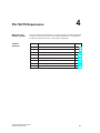
What Does this
Chapter Contain?
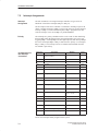
Chapter
Overview
You can enhance the functionality of your PG 740 PII by installing additional
modules or powerful processors. This chapter describes how to expand your
PG 740 PII. Please observe the relevant Safety Guidelines.
Section
Description
Page
4.1
Opening the Unit
4-2
4.2
Functional Units Visible after Opening the Unit
4-4
4.3
Block Diagram of the Mother Board
4-5
4.4
Installing Expansion Modules
4-11
4.5
Installing Memory Expansion Cards
4-13
4.6
Backup Battery
4-16
4.7
Processor Upgrade
4-17
4.8
Closing the Unit
4-17
Programming Device PG 740 PII
C79000-G7076-C749-02
4-1
PG 740 PII Expansions
4.1
Opening the Unit
Prerequisites
!
Limitation of
Liability
The programming device is designed to enable any necessary maintenance
work to be carried out quickly and at low cost.
Caution
The electronic components of the printed-circuit boards are extremely
sensitive to electrostatic discharge. When handling the boards, you must
follow the guidelines for electrostatically-sensitive components (ESD
guidelines) at the end of this book.
All technical specifications and licenses apply only to expansion functions
approved by Siemens.
No liability can be assumed for functional constraints caused by the use of
devices and components of other manufacturers.
All modules and components in the PG 740 PII are electrostatically sensitive.
Please read the ESD guidelines at the end of this book carefully. The
following sign on cabinets, module racks or packaging warns that
electrostatically-sensitive modules are present.
Before Opening
the Unit
The following rules are mandatory when carrying out any work on the open
unit, and should be read carefully before opening the unit:
Before you disconnect the power supply cable, discharge any electrostatic
charge on your body. You can do this by touching metallic parts, such as
screws, on the rear panel of the PG 740 PII.
Discharge any electrostatic charge from tools that you are using.
Wear a grounding wrist strap if you are handling components.
Leave components and modules in their packing until you are ready to
install them.
Disconnect the PG 740 PII from its power supply before plugging in or
removing any modules or components.
Touch components and modules only on their edges. Above all, do not
touch the connecting pins and printed conductors.
Do not operate the PG 740 PII with the cover open.
4-2
Programming Device PG 740 PII
C79000-G7076-C749-02
PG 740 PII Expansions
Tools
Use a suitable TORX or Phillips screwdriver to loosen the M3 combi TORX
screws.
Opening the
PG 740 PII
Open your PG 740 PII as follows:
1. Switch off the PG 740 PII, pull out the power plug, and remove all
connecting cables.
2. Swing the keyboard down into position.
3. Now undo the two screws on the rear panel. Bring the unit into the 90°
(horizontal) position. Use the extra pull-out support in the stand to
improve the stability of the unit.
4. Push in the snap catches at the bottom with a small screwdriver.
5. Pull off the rear panel to the rear using the carrying handle.
6. Swing the unit back into the vertical position.
Locking screw
Locking screw
Snap catches at base of device
Figure 4-1
Programming Device PG 740 PII
C79000-G7076-C749-02
Rear View of the PG 740 PII
4-3
PG 740 PII Expansions
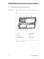
4.2
Functional Units Visible after Opening the Unit
Functional Units
The functional units are visible once you have removed the top section of the
unit.
8
4
3
9
2
5
intel pentium II
6
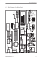
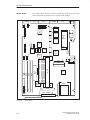
1
1
Drives
2
Ventilator
3
Motherboard
4
Expansion module
(not part of basic shipping)
Figure 4-2
4-4
7
5
Bus board with ISA and
shared PCI/ISA slots
6
Power supply
7
Bracing
8
Base for DIMM memory
9
Slot 1 of Pentium II
The PG 740 PII Opened
Programming Device PG 740 PII
C79000-G7076-C749-02
66 MHz
Soft On/Off
’ABT245
29F040
BIOS
512 KB
Page select
for 4
128 Kpages
2
82443LX
Speaker on board
Optional
USB Port1/2
16Bit
VCC/
VPP
Card bus
controller PCI1131
Cntl.
ISA bus 16-bit data, 24-bit addresses, 5V
System controller
GTL host bus
Cntl.
5V / 2.5V
DC / DC
L2–Cache
Slot 1
HD(0..63)
+ ECC
512K
PentiumII 266 MHz
HA(0..31)Cntl.
VCC Core:3.3V
Multimedia
CD-ROM
SIMATIC
S5 submodulee
Memory
card
PC card
Isolated
12MB/s
L2–DP
RS485
ASPC/2
Module
3.5”Floppy
1.44 MB
Speaker
Micro
Ultra–IO
87317
Speaker/Headphone
CT65555
VGA controller
64
3.3 Volt EDO
256K x16
256K x16
256K x16
256K x16
2 MB on-board frame buffer
ICS9147–03
Clock synthesizer
Keyboard with/without trackball
ÎÎÎ
ÎÎ
ÎÎ
Î
ÎÎ
ÎÎ
Î
ÎÎÎ
Cardbus /
Submodule
SIMATIC S5/S7
PCI9050
PCI –ISA–Bridge
CS4238B
Crystal
ECC
DIMM Socket 2 8,16,32,64,128MB
SDRAM ( FPM, EDO )
Audio
ECC
DIMM Socket 1 8,16,32,64,128MB
SDRAM ( FPM, EDO )
SKAN
’ABT245
VCC/
VPP
ATA–33
Hard disk
Primary
ECC
DIMM Socket 0 8,16,32,64,128MB
SDRAM ( FPM, EDO )
Secondary
64 +8(ECC)
32-bit address bus, 64-bit data bus + ECC ( 66 MHz bus frequency )
Voltage
regulation
module
( 33/30 MHz bus frequency )
16Bit
3.3/5 V PCI bus AD0..31
+5VAUX
–12V
+12V
+3.3V
PIIX4
Power
supply
–5V
Termination
Cntl.
+5V
HA (0..31)
AD ( 0..31)
5V–>1.5V
GTL– Power supply 5.42A
Termination voltage Vtt=1.5V
HD (0..63)
AD ( 0..31)
Fuse
Cntl.
Programming Device PG 740 PII
C79000-G7076-C749-02
AD ( 0..31)
Figure 4-3
RISER
PS/2
Mouse
COM1
75150/154
TTY/PLC
Communication
TTL
TTY
Bus board
20p
ext. XGA
Modem
COM2
75150/154
TFT
Centronics
Printer
EPP/ECP
LPT1
protection
RC network
1 ISA/PCI slot
1 PCI slot
1024x768 LCD
XGA display 13.3”
1280x1024x256
4.3
LVDS
DC/DC
PG 740 PII Expansions
Block Diagram of the Mother Board
Block Diagram of the PG 740 PII
4-5
PG 740 PII Expansions
Mother Board
The mother board is the heart of the PG 740 PII. Here, data are processed and
stored, and interfaces and device I/Os controlled and managed.
X11
X10
X800
X9
X7
X18
X404
X16
X402
X17
X504
S2
X409
1234
1
X503
S1
1234
X502
ASPC2
X1
Progr.submodule
PLX9050
X24
EDO
EDO
X60
C&T65555
X501
EDO
EDO
X63
1
CS4228
PCI1131
X6
PIIX4
X62
X25
X40
1
2
X5
X13
1
2
1
2
X3
X4
X12
X27
DIMM
DIMM
ÏÏÏÏ
ÏÏÏÏ
ÏÏÏÏ
ÏÏÏÏ
ÏÏÏÏ
ÏÏÏÏ
ÏÏÏÏ
ÏÏÏÏ
ÏÏÏÏ
ÏÏÏÏ
ÏÏÏÏ
ÏÏÏÏ
S3
2
1
DIMM
X37
2
1
X61
BGA324
4321
X31
82317
X601
X21
X20
X19
X403
X14
SCAN
ASIC
X701
X700
Processor plugged on X12
Figure 4-4
4-6
Mother Board
Programming Device PG 740 PII
C79000-G7076-C749-02
PG 740 PII Expansions
Components on
the Mother Board
The following components are located on the mother board of the
PG 740 PII:
ÁÁÁÁÁÁÁÁÁÁÁÁÁÁÁÁÁÁÁÁÁÁÁÁÁÁÁÁÁÁÁ
ÁÁÁÁÁ
ÁÁÁÁÁÁ
ÁÁÁÁÁÁÁÁÁÁÁÁÁÁÁÁÁÁÁÁ
ÁÁÁÁÁÁÁÁÁÁÁÁÁÁÁÁÁÁÁÁÁÁÁÁÁÁÁÁÁÁÁ
ÁÁÁÁÁÁÁÁÁÁÁÁÁÁÁÁÁÁÁÁÁÁÁÁÁÁÁÁÁÁÁ
ÁÁÁÁÁ
ÁÁÁÁÁÁ
ÁÁÁÁÁÁÁÁÁÁÁÁÁÁÁÁÁÁÁÁ
ÁÁÁÁÁÁÁÁÁÁÁ
ÁÁÁÁÁÁÁÁÁÁÁÁÁÁÁÁÁÁÁÁÁÁÁÁÁÁ
ÁÁÁÁÁ
ÁÁÁÁÁÁÁÁÁÁÁÁÁÁÁÁÁÁÁÁ
ÁÁÁÁÁÁÁÁÁÁÁÁÁÁÁÁÁÁÁÁÁÁÁÁÁÁÁÁÁÁÁ
ÁÁÁÁÁÁÁÁÁÁÁÁÁÁÁÁÁÁÁÁÁÁÁÁÁÁÁÁÁÁÁ
ÁÁÁÁÁ
ÁÁÁÁÁÁÁÁÁÁÁ
ÁÁÁÁÁÁÁÁÁÁÁÁÁÁÁÁÁÁÁÁÁÁÁÁÁÁ
ÁÁÁÁÁÁÁÁÁÁÁÁÁÁÁÁÁÁÁÁ
ÁÁÁÁÁÁÁÁÁÁÁÁÁÁÁÁÁÁÁÁÁÁÁÁÁÁÁÁÁÁÁ
ÁÁÁÁÁÁÁÁÁÁÁÁÁÁÁÁÁÁÁÁÁÁÁÁÁÁÁÁÁÁÁ
ÁÁÁÁÁÁÁÁÁÁÁÁÁÁÁÁÁÁÁÁÁÁÁÁÁÁÁÁÁÁÁ
ÁÁÁÁÁ
ÁÁÁÁÁÁ
ÁÁÁÁÁÁÁÁÁÁÁÁÁÁÁÁÁÁÁÁ
ÁÁÁÁÁÁÁÁÁÁÁÁÁÁÁÁÁÁÁÁÁÁÁÁÁÁÁÁÁÁÁ
ÁÁÁÁÁÁÁÁÁÁÁÁÁÁÁÁÁÁÁÁÁÁÁÁÁÁÁÁÁÁÁ
ÁÁÁÁÁ
ÁÁÁÁÁÁ
ÁÁÁÁÁÁÁÁÁÁÁÁÁÁÁÁÁÁÁÁ
ÁÁÁÁÁÁÁÁÁÁÁÁÁÁÁÁÁÁÁÁÁÁÁÁÁÁÁÁÁÁÁ
Designation
Name
Functions
X1
Slotbus
ISA/PCI connector between mother board and bus module
X3
CD ROM
Secondary IDE interface, standard ribbon cable
X4
HD prim.
Primary IDE interface, standard ribbon cable
X5
Floppy disk
Floppy disk interface
X6
DIN keyboard plug
X7
Keyboard
connection
Mouse connection
X9
LPT
Parallel interface for LPT1/printer connection (25-contact Centronics)
X10
COM 1
Serial port 1 (25-contact)
X11
COM 2
Serial port 2 (standard 9-contact)
X12
CPU
Processor with heat sink (Slot 1)
X13
Power
Power supply connection for mother board
X14
Fan
Connection for device fan
X16
Display module
Connection for flexible cable to display module
X17
Receptacle
Receptacle for TTY transmitter module
X18
Receptacle
Receptacle for TTY receiver module
PS/2 mouse plug
X19/X20/X21 RAM
Receptacle for DRAM DIMM
X24
Battery
Plug for lithium battery
X25
Hard disk power
supply
Power supply for hard disk drives
X27
VRM
Voltage regulation module: voltage supply for the processor
X31
Secondary IDE
Secondary IDE-Port für LS120
X37
Fan
Fan connection +12V, CPU
ÁÁÁÁÁÁÁÁÁÁÁÁÁÁÁÁÁÁÁÁÁÁÁÁÁÁÁÁÁÁÁ
ÁÁÁÁÁÁÁÁÁÁÁÁÁÁÁÁÁÁÁÁÁÁÁÁÁÁÁÁÁÁÁ
ÁÁÁÁÁÁÁÁÁÁÁÁÁÁÁÁÁÁÁÁÁÁÁÁÁÁÁÁÁÁÁ
X40
USB
Plug connector for USB option
X402
VGA
Standard VGA (15-contact)
X403
Display inverter
Plug connector for display inverter
X404
On/off switch
Plug connector for on/off switch
X409
Display
LVDS interface for display
X60
Microphone
Plug connector for microphone interface
X61
Headphones
Plug connector for headphone interface
X62
Loudspeaker
Connection for internal loudspeaker
X63
CD audio
Plug connector for CD-ROM audio output
X601
PCMCIA
PG 740 PII
Cardbus/PCMCIA interface
X700
SIMATIC programming submodule interface
X701
Programming
submodule
Memory card
X800
MPI/DP 12
MPI/DP interface
S1
Switch 1
Display type, clock
S2
Switch 2
CPU clock, flash EPROM, TTY interface
S3
Switch 3
Switch CPU clock
ÁÁÁÁÁÁÁÁÁÁÁÁÁÁÁÁÁÁÁÁÁÁÁÁÁÁÁÁÁÁÁ
ÁÁÁÁÁÁÁÁÁÁÁÁÁÁÁÁÁÁÁÁÁÁÁÁÁÁÁÁÁÁÁ
ÁÁÁÁÁÁÁÁÁÁÁ
ÁÁÁÁÁÁÁÁÁÁÁÁÁÁÁÁÁÁÁÁÁÁÁÁÁÁ
ÁÁÁÁÁ
ÁÁÁÁÁÁÁÁÁÁÁÁÁÁÁÁÁÁÁÁ
ÁÁÁÁÁÁÁÁÁÁÁÁÁÁÁÁÁÁÁÁÁÁÁÁÁÁÁÁÁÁÁ
ÁÁÁÁÁÁÁÁÁÁÁÁÁÁÁÁÁÁÁÁÁÁÁÁÁÁÁÁÁÁÁ
ÁÁÁÁÁÁÁÁÁÁÁÁÁÁÁÁÁÁÁÁÁÁÁÁÁÁÁÁÁÁÁ
Programming Device PG 740 PII
C79000-G7076-C749-02
SIMATIC memory card interface
4-7
PG 740 PII Expansions
ÁÁÁÁÁÁÁÁÁÁÁÁÁÁÁÁÁÁÁÁÁÁÁÁÁÁÁÁÁÁ
ÁÁÁÁÁÁÁÁÁÁÁÁÁÁÁÁÁÁÁÁÁÁÁÁÁÁÁÁÁÁ
Designation
X501/ 502
X503/ 504
Name
Programming
submodule
RS 485/hybrid
Switching the
PG 740 PII to
Active/Passive
Functions
Plug/socket connector in which the programming submodule is positioned
Plug/socket connector in which the RS 485/hybrid is positioned
When the PG 740 PII leaves the factory, the COM1 (TTY) serial port is
switched to active (20 mA current loop). If you are connecting two
programming devices via the COM1 (TTY) serial port, you must switch one
of the ports to passive. The PG 740 PII has a switch on its mother board for
this purpose.
Switch Position
S3
S1 S2
intel pentium II
Figure 4-5
4-8
Position of Switches S1, S2, and S3
Programming Device PG 740 PII
C79000-G7076-C749-02
PG 740 PII Expansions
Switch Settings
The following switch settings are only listed for information purposes. They
are set in the factory and must not be changed.
x means that this switch is irrelevant to the described function.
BIOS Source
TTY Settings
S2
Clock Settings
S2, S3
S2 (3)
Function
off
Boot EPROM activated (standard setting)
on
Boot EPROM deactivated (boot module required)
S2 (1)
S2 (2)
Function
on
on
Active TTY interface
(standard setting)
off
x
TTY transmitter loop, isolated from current source
(passive setting)
x
off
TTY receiver loop, isolated from current source
(passive setting)
S2(4) S3(4) S3(3) S3(2) S3(1)
ISA Bus
Clock
PCI
Bus
Clock
CPU
Bus
Clock
CPU Core
Clock
(CPUInternal)
off
off
off
on
off
8.25MHz
33MHz
66MHz
266MHz
off
off
off
off
off
8.25MHz
33MHz
66MHz
133MHz
off
off
on
off
off
8.25MHz
33MHz
66MHz
200MHz
off
off
on
on
off
8.25MHz
33MHz
66MHz
333MHz
Note
Processor upgrade
If the processor is upgraded, for example, to a processor with a different
frequency, a BIOS upgrade must also be executed.
Programming Device PG 740 PII
C79000-G7076-C749-02
4-9
PG 740 PII Expansions
Standard
Settings
ON
1
2
S2
3
4
OFF
OFF
4
3
1
S3
2
ON
Figure 4-6
Standard Settings of Switches S2 (1 to 4) and S3 (1 to 4) for 333 MHz
Pentium PII CPU
Standard
Settings for the
Display
ON
1
S1
2
3
4
OFF
Figure 4-7
Standard Settings for the Display
The switch settings are set up correctly for the display and must not be
changed.
4-10
Programming Device PG 740 PII
C79000-G7076-C749-02
PG 740 PII Expansions
4.4
Installing Expansion Modules
Installing
Expansion
Modules
You can extend the functionality of your PG 740 PII by installing additional
modules. Two expansion slots are provided on the bus board for this purpose.
The following modules can be fitted:
Slot
Module
1
ISA 170 mm long
2
ISA or PCI 170 mm
The current drawn per ISA or PCI module must not exceed the following
values:
+5V
1.6 A
+ 12 V
0.3 A
- 12 V
50 mA
-5V
50 mA
Signals
one TTL load
intel pentium II
Figure 4-8
Programming Device PG 740 PII
C79000-G7076-C749-02
Open PG 740 PII with Expansion Module
4-11
PG 740 PII Expansions
!
Caution
Risk of damage
The electronic components of the printed-circuit boards are extremely
sensitive to electrostatic discharge. Please observe the guidelines for
electrostatically-sensitive devices (ESD guidelines), otherwise the module or
device may be damaged.
Plugging in the
Module
You plug expansion modules in as follows:
1. Open the unit as described in Section 4.1.
2. Remove the dummy plate on the casing side panel.
3. Plug the module into a free slot.
4. Bolt the module backplane to the casing side panel.
5. Close the unit (see Section 4.8).
4-12
Programming Device PG 740 PII
C79000-G7076-C749-02
PG 740 PII Expansions
4.5
Installing Memory Expansion Cards
Standard Memory
There are three ECC-compatible slots for 72-bit DIMM memory expansion
submodules on the mother board. The basic configuration consists of
64 Mbytes. You can extend it up to a maximum of 384 Mbytes.
Only one submodule must be fitted. You can fit a combination of EDO and
SDRAM submodules.
If ECC submodules are fitted in combination with non-ECC submodules, the
memory works without ECC backups or correction.
Organization
Size in Mbytes
Type
Access Time/
Frequency
8Mx64
64
EDO
60 ns
16Mx64
128
EDO
60 ns
8Mx72
64
EDO with ECC
60 ns
16Mx72
128
EDO with ECC
60 ns
8Mx64
64
SDRAM
>=83 MHz
16Mx64
128
SDRAM
>=83 MHz
8Mx72
64
SDRAM with ECC
>=83 MHz
16Mx72
128
SDRAM with ECC
>=83 MHz
You will find the order numbers for the memory expansion cards in the
Product Information Bulletin.
!
Caution
Risk of damage
The electronic components on the printed circuit boards are highly sensitive
to electrostatic discharge. When handling the boards or cards, you must
follow the guidelines for electrostatically-sensitive components (ESD
guidelines at the end of this manual).
Programming Device PG 740 PII
C79000-G7076-C749-02
4-13
PG 740 PII Expansions
X19
X20
X21
Figure 4-9
Installing the
DIMM Cards
Location of the Memory Slots
Plug the DIMM memory cards in as follows:
1. First open the unit as described in Section 4.1.
2. Plug the cards in vertically, making sure the cut-out on the connector end
of the DIMM card engages properly.
3. Gently press the card downwards.
!
Caution
Risk of damage
Note that only qualified personnel should be allowed to work on the open unit,
so the warranty on the device is not affected. Authorized Siemens maintenance
and repair centers listed at the end of the Product Information Bulletin offer you
a specialist maintenance service.
!
Caution
Expansion cards are sensitive components. It is essential that you observe
the information in the manual (Section 4.5).
4. Close the device (see Section 4.8).
4-14
Programming Device PG 740 PII
C79000-G7076-C749-02
PG 740 PII Expansions
!
Caution
Risk of damage
The cards must sit firmly in their sockets, otherwise they might be damaged.
Plug the cards into their sockets vertically.
Installation
The system recognizes the new memory configuration automatically. When
you power up the unit, the base and extended memory information appears
automatically on the screen.
Programming Device PG 740 PII
C79000-G7076-C749-02
4-15
PG 740 PII Expansions
4.6
Backup Battery
Battery Power
Supply for
Real-Time Clock
and Configuration
A backup battery (3.6 V lithium battery) powers the real-time clock even
after the PG 740 PII is switched off. In addition to the time of day, all the
information about the PG 740 PII’s configuration is stored in RAM. If the
backup battery fails or is removed, all this data is lost.
Because the clock uses very little power and the lithium battery has a high
capacity, the battery can provide backup power for the real-time clock for
several years.
Battery too Low
If the battery voltage is too low, the current time and the configuration data
stored in the RAM are lost.
Changing the
Battery
In this case, you must replace the backup battery. The battery is located
behind the power supply module on the mother board.
To change the battery, proceed as follows:
1. Switch your PG 740 PII off, unplug the power cable and detach all
connecting cables.
2. Open the unit as described in Section 4.1.
3. Undo the three screws of the bracing between the mother board and the
drive support.
4. Remove the power supply by undoing the two screws on its right-hand
side and the two screws on the mother board.
5. Unplug the power supply cable from the power supply.
6. Slide the power supply to the left as far as the stop. You can now lift the
power supply out of the unit.
7. Now replace the backup battery, which is attached to the mother board by
a short length of cable.
8. Fix the new battery to the mother board with a cable binder.
9. Replace the power supply and close the unit as described in Section 4.8.
!
Caution
Risk of damage
You may only replace the lithium battery with an identical battery or a
battery type recommended by the manufacturer of your PG 740 PII
(order no. W79084-E1003-B1).
You should dispose of used batteries in keeping with local regulations. If
returned to the manufacturer, the batteries will be disposed of correctly.
Resetting SETUP
4-16
If you change the backup battery, you must reset your PG 740 PII’s
configuration with the SETUP program (Chapter 5).
Programming Device PG 740 PII
C79000-G7076-C749-02
PG 740 PII Expansions
4.7
Processor Upgrade
You can increase the power of your PG 740 PII by installing other Pentium II
processors. Please contact your nearest service center or sales representative
for more information.
Note
Processor upgrade
If the processor is upgraded, for example, to a processor with a different
frequency, a BIOS upgrade must also be executed.
4.8
Closing the Unit
Closing the Unit
To close the unit, proceed as follows:
1. Bring the unit into its upright position.
2. Place the rear panel (top edge with guides) on the casing in an inclined
position.
3. Swing the rear panel down over the casing until the catches on the
underside of the casing engage.
4. Bolt the rear panel tight with the two screws.
5. The unit is now ready for operation again.
Programming Device PG 740 PII
C79000-G7076-C749-02
4-17
PG 740 PII Expansions
4-18
Programming Device PG 740 PII
C79000-G7076-C749-02
5
Configuring the PG 740 PII
What Does this
Chapter Contain?
Chapter
Overview
In this chapter, you will learn how to configure your programming device.
This will be necessary if you have made any changes to your system by
adding, removing or replacing an adapter card, a memory expansion card or a
system module.
ÁÁÁÁÁÁÁÁÁÁÁÁÁÁÁÁ
ÁÁÁÁÁÁÁÁÁÁÁÁÁÁÁÁ
ÁÁÁÁÁÁÁÁÁÁÁÁÁÁÁÁ
ÁÁÁÁÁÁÁÁÁÁÁÁÁÁÁÁ
ÁÁÁÁÁÁÁÁÁÁÁÁÁÁÁÁ
ÁÁÁÁÁÁÁÁÁÁÁÁÁÁÁÁ
ÁÁÁÁÁÁÁÁÁÁÁÁÁÁÁÁ
ÁÁÁÁÁÁÁÁÁÁÁÁÁÁÁÁ
Section
5.1
5.1.1
5.1.2
5.1.3
5.1.4
5.1.5
Programming Device PG 740 PII
C79000-G7076-C749-02
Description
Page
Changing the System Configuration with SETUP
5-2
The Main Menu
5-5
The Advanced Menu
5-15
The Security Menu
5-21
The Power Menu
5-23
The Exit Menu
5-25
5-1
Configuring the PG 740 PII
5.1
Changing the Device Configuration with BIOS SETUP
Changing the
Device
Configuration
The device configuration of your programming device is set for working with
the software supplied with the unit. You should only change the preset values
if you have modified your device in any way, or if a fault occurs when the
unit is powered up.
The changes you make will not become effective until the device is restarted.
When you exit the setup program, the device is automatically rebooted.
SETUP
Program
The SETUP program is in the ROM-BIOS. Information on the system
configuration is stored in the battery-backed clock memory of the
PG 740 PII.
You can use SETUP to set the hardware configuration (for example, type of
hard disk) and define the system characteristics. You can also use SETUP to
set the time and date in the clock chip.
Incorrect SETUP
Data
If incorrect SETUP data are recognized when booting the system, the BIOS
prompts you to:
Start SETUP by pressing F2 or
Continue booting by pressing F1.
Starting SETUP
On completion of the startup test, the BIOS requests you to start the SETUP
program with the following screen prompt:
PRESS < F2 > to enter SETUP
Start SETUP as follows:
1. Reset your PG 740 PII (warm or cold restart).
2. Press the F2 key as long as the BIOS prompt is on the screen.
Default Setting
The F9 key or “Get Default Values” command in the exit menu sets the
default parameters in the screen forms.
SETUP Menus
The various menus and submenus are listed on the following pages. You can
obtain information on the SETUP entry selected from the Item Specific Help
part of the relevant menu.
5-2
Programming Device PG 740 PII
C79000-G7076-C749-02
Configuring the PG 740 PII
Screen Display
Following
Power-On
With the standard setting of your programming device, the display shown
below appears following power-on:
PhoenixBIOS Release 6.0 – G849–A901
Copyright 1985-1995 Phoenix Technologies Ltd., All Rights
Reserved.
SIEMENS PG 740 Pentium II V06
CPU = Pentium 333 MHz
640K System RAM Passed
064M Extended RAM Passed
0512K Cache SRAM Passed
System BIOS shadowed
Video BIOS shadowed
UMB upper limit segment address: F1xx
Fixed Disk 0: [name of installed disk drive]
ATAPI CD-ROM: [name of installed CD-ROM drive]
Press F2> to enter SETUP
If you press the F2 key when the above display is shown, you select the
ROM-based BIOS setup program. In this program you can set a number of
system functions and hardware configurations of your programming device.
The standard settings are effective on delivery. You can change these settings
using the BIOS setup. The modified settings become effective when you have
saved them and terminated the BIOS setup.
The following screen form appears when you start the BIOS setup:
PhoenixBIOS Setup Utility
Header
Main
Menu bar
Advanced
Security
System Date:
Diskette A:
Diskette B:
Primary Master
Primary Slave
Secondary Master
Secondary Slave
[ 1.44 MB, 31/2” ]
[ Disabled]
[5250MB]
[None]
[None]
[None]
Memory Cache:
Boot Options
Keyboard Features
Hardware Options
System Memory:
Extended Memory:
Operating keys
F1
Help
ESC Exit
Figure 5-1
Programming Device PG 740 PII
C79000-G7076-C749-02
Exit
[ 15:35:32 ]
[ 01/23/1998 ]
System Time:
Selectable
submenu
Power
Item Specific Help
Shift-Tab
Tab
selects field.
, or
Enter
Example:
Hour/Minute/Second
Month/Day/Year
[Write Back]
Help window
640 KB
64512 KB
Select Item
+ / – Change Values
F9
Select Menu
Enter Select
F10 Save and Exit
Sub-Menu
Setup Defaults
Main SETUP Menu
5-3
Configuring the PG 740 PII
Menu Structure
The screen is divided into four parts. In the top part, you can select the menu
forms [Main], [Advanced], [Security], [Power], [Exit]. In the left of the
center part you can select various settings or submenus. Brief help texts
appear on the right for the currently selected menu entry. The bottom part
contains information for operator inputs.
Yellow stars to the left of the interface designation (for example, Internal
COM 1) indicate a resource conflict between the interfaces managed by the
BIOS. In this case you should select the default settings (F9) or eliminate the
conflict by changing the setting.
You can move between the menu forms using the cursor keys [←] and [→].
Menu
ENTER Key
Meaning
Main
System functions are set here
Advanced
An extended system configuration can be set here
Security
Security functions are set here, for example, a password
Power
Power saving functions can be selected here
Exit
Used for terminating and saving
Press the Enter key to open a drop-down menu in which you can use the
cursor keys to move to and select the values. To exit one of these menus,
press either ESC (exit without changes) or Return (selected setting becomes
effective when device is rebooted).
If a line is marked with a triangle it contains a submenu. You can exit a
submenu by pressing ESC. The changes you have selected will become
effective when the device is rebooted.
5-4
Programming Device PG 740 PII
C79000-G7076-C749-02
Configuring the PG 740 PII
5.1.1
The Main Menu
PhoenixBIOS Setup-Utility
Main
Advanced
Security
System Time:
F1
Help
ESC Exit
Figure 5-2
Settings in the
Main Menu
[ 1.44 MB, 31/2” ]
[ Disabled]
[5250MB]
[None]
[ATAPI]
[Removable]
Memory Cache:
Boot Options
Keyboard Features
Hardware Options
System Memory:
Extended Memory:
Exit
[ 15:35:32 ]
[ 01/23/1998 ]
System Date:
Diskette A:
Diskette B:
Primary Master
Primary Slave
Secondary Master
Secondary Slave
Selectable
submenu
Power
Item Specific Help
,
Shift-Tab
Tab
selects field.
, or
Enter
Example:
Hour/Minute/Second
Month/Day/Year
[Write Back]
Help window
640 KB
64512 KB
Select Item
+ / – Change Values
F9
Select Menu
Enter Select
F10 Save and Exit
Sub-Menu
Setup Defaults
Main SETUP Menu
In the Main menu you can move upwards and downwards using the cursor
keys [↑] and [↓] to select the following system parameters:
Menu Item
Function
System Time
Used to display and set the current time
System Date
Used to display and set the current date
Diskette A
Name of installed disk drive
Diskette B
Type setting for a second disk drive
Memory Cache
For setting cache options
Via submenus
Primary
Name of installed drives
Secondary
Name of installed drives
Boot Options
For setting boot options
Keyboard Features
For setting keyboard interface (for instance,
NUM-LOCK, typematic rate)
Hardware Options
For setting PG 740 PII hardware options
Programming Device PG 740 PII
C79000-G7076-C749-02
5-5
Configuring the PG 740 PII
System Time and
System Date
System Time and System Date indicate the current values. Once you have
selected the appropriate option, you can use the [+] and [–] keys to modify
the time setting
Hour:Minute:Second
and the date
Month/Day/Year.
You can move between the entries in the date and time options (for example,
from hour to minute) using the tabulator key.
Diskette A/
Diskette B
The names of the installed disk drives in the programming device are set
here. The following entries are possible:
[Disabled]
If a disk drive is not fitted (standard setting for disk drive B)
[360 KB, 5 1/4”]
[1.2 MB, 5 1/4”]
[720 KB, 3 1/2”]
[1.44 MB, 3 1/2”]
Standard setting for installed disk drive A
[2.88 MB, 3 1/2”]
5-6
Programming Device PG 740 PII
C79000-G7076-C749-02
Configuring the PG 740 PII
Primary Master/sxa
Primary Slave
Secondary Master –
Secondary Slave
The system jumps to the following submenu when you select this type of
menu option:
PhoenixBIOS Setup Utility
Main
Advanced
Security
Power
Exit
Primary Master [5250MB]
Item Specific Help
Type:
Cylinders:
Heads:
Sectors:
Maximum Capacity:
[Auto]
[10850]
[
15]
[
63]
5250MB
Multi-Sector Transfers:
LBA Mode Control:
32 Bit I/O:
Transfer Mode:
[16 Sectors]
[Enabled]
[Enabled]
[FPIO 4 / DMA 2]
[Mode2]
Ultra DMA Mode:
F1
Help
ESC Exit
Figure 5-3
[AUTO] (recommended)
Autotypes installed
IDE–devices
[USER]
Enter parameters of
IDE-devices installed
at this connection
[1-39]
Select predetermined type of
hard-disk drive
Select Item
+ / – Change Values
Select Menu
Enter Select
Sub-Menu
F9
Setup Defaults
F10 Previous Values
Example: “Primary Master”
The parameters which you can select here are usually saved on the respective
IDE drive. With the setting “Auto” in the “Type” these values are
automatically read from the drive and saved (Autodetect).
Option “Type”
If you select the option “Type” for a drive which does not exist, an abort is
executed after approximately one minute as a result of a timeout and the
existing entries remain unchanged. It is therefore only meaningful to carry
out an autodetect for interfaces to which drives are connected.
Under certain circumstances it may be necessary to deviate from the
proposed hard disk parameters. In this case, select the corresponding menu
option and then the desired value using the [+] and [–] keys. Enter “none” in
the option “Type” if no drive is connected, or a number from 1 to 39 if a
predefined type of hard disk is to be used.
Select “User” if you wish to define your own type of hard disk; you must
then additionally enter the hard disk-specific parameters in the options
“Cylinders,” “Heads,” “Sectors/Track,” “Write Precomp.”
Programming Device PG 740 PII
C79000-G7076-C749-02
5-7
Configuring the PG 740 PII
Option “Multi-Sector
Transfers”
The number of sectors which are transmitted per interrupt are transferred in
the option “Multi-Sector Transfers.” The value depends on the drive and
should only be set via the “Type” field by setting the “Auto” option.
Disabled
2,4,8,16
sectors
Option “LBA Mode
Control”
“Enabled” in the option “LBA Mode Control” (enabled, disabled) means that
hard disk capacities greater than 528 Mbytes are supported. The value
depends on the drive and should only be set via the “Type” field by setting
the “Auto” option.
Option “32 Bit I/O”
The type of access to the drive is defined in the option “32 Bit I/O”:
Option “Transfer
Mode” or Ultra DMA
Mode
Disabled
16-bit access
Enabled
32-bit access (default)
The interface transmission rate is set in the option “Transfer Mode.” The
value depends on the drive and should only be set via the “Type” field by
setting the “Auto” option.
You leave the submenu using the ESC key.
5-8
Programming Device PG 740 PII
C79000-G7076-C749-02
Configuring the PG 740 PII
Option “Memory
Cache”
The following pop-up menu appears when you select the option “Memory
cache” in the main menu:
PhoenixBIOS Setup Utility
Main
Advanced
System Time:
System Date:
Diskette A:
Diskette B:
Primary Master
Primary Slave
Secondary Master
Secondary Slave
Memory Cache:
Boot Options
Keyboard Features
Hardware Options
System Memory:
Extended Memory:
F1
Help
ESC Exit
Figure 5-4
Security
Power
Exit
[ 15:35:32 ]
[ 01/23/1998 ]
Item Specific Help
[ 1.44 MB, 31/2” ]
[ Disabled]
[5250MB]
[None]
[None]
[None]
Disabled
[Write
Write Through
Write Back
Controls caching of system
conventional memory and
memory above one megabyte
640 KB
64512 KB
Select Item
+ / – Change Values
F9
Select Menu
Enter Select
F10 Save and Exit
Sub-Menu
Setup Defaults
“Memory Cache” Menu
A cache is a fast intermediate memory located between the CPU and the
memory (DRAM). Repeated memory access operations are executed in the
fast cache, and not in the main memory, provided the function is enabled.
Occasionally, it may be necessary to disable the cache with certain hardware
and software because required program run times or wait times are shortened
by the fast cache.
[Disabled]
Cache is disabled.
[Write Through]
Write access is only concluded when an entry is made in the
main memory.
[Write Back]
Write access is concluded immediately, the entry in the main
memory takes place in the background. (default)
Programming Device PG 740 PII
C79000-G7076-C749-02
5-9
Configuring the PG 740 PII
Option “Boot
Options”
The following submenu appears when you select the option “Boot Options”
in the main menu:
PhoenixBIOS Setup-Utility
Main
Advanced
Security
Power
Exit
Boot Options
Item Specific Help
[Enabled]
QuickBoot Mode:
SETUP prompt:
Allows the system to skip certain tests while booting. This
will decrease the time needed
to boot the system.
[Enabled]
POST Errors:
[Enabled]
Floppy check:
[Disabled]
Summary screen:
[Enabled]
Boot Sequence:
1.
[Diskette Drive]
2.
[Removable Devices]
3.
[Hard Drive]
4.
[ATAPI CD-ROM Drive]
Hard Drive Boot Device
Diskette Boot Device
F1
Help
ESC Exit
Figure 5-5
5-10
Select Item
+ / – Change Values
Select Menu
Enter Select
F9
Sub-Menu
Setup Defaults
F10 Save and Exit
“Boot Options” Submenu
Quick Boot
Mode
Allows the system to skip certain tests while booting. This will
decrease the time needed to boot the system.
SETUP prompt
During the system loading phase, the following SETUP prompt is
output at the bottom of the screen: PRESS <F2> to enter Setup.
POST errors
The loading procedure is aborted and must be acknowledged with
F1 if an error is detected during the system loading phase.
Floppy check
During the system loading phase, the floppy head is moved by a
number of steppings to the inside, and then returned again. This
test is useful because the drive is initialized again in the process.
Summary screen
The most important system parameters are output on the display at
the end of the system loading phase.
Boot Sequence
Here you can define the device sequence from which a system start
(boot attempt) is to be carried out first.
Removable devices:
allows you to designate future ATAPI
drives such as LS120, for instance.
Programming Device PG 740 PII
C79000-G7076-C749-02
Configuring the PG 740 PII
Option “Hard Drive
Boot Device”
In this dialog box you can determine whether the device should be booted
from the IDE primary master first. The hard disk is connected to the primarymaster interface at the factory.
PhoenixBIOS Setup Utility
Main
Advanced
Security
Power
Exit
Hard Drive Boot Device
Item Specific Help
1. [Primary Master]
2. [Alternate Device]
Move the prefered boot device
to top of list.
The order of the list will be the
order of boot sequence.
Use < > or < > to select a device, then press <+> to move it
up the list, or <–> to move it
down the list.
Press <Esc> to exit the menu.
F1
Help
ESC Exit
Figure 5-6
Submenu
“Diskkete Boot
Device”
Select Item
+ / – Change Values
Select Menu
Enter Select
Sub-Menu
F9
Setup Defaults
F10 Save and Exit
“Hard Drive Boot Device” Submenu
In this dialog box, you define from which disk drive the system is to be
booted. The 1.44 MB disk drive is installed as default.
PhoenixBIOS Setup Utility
Main
Advanced
Security
Power
Exit
Diskette Boot Device
Item Specific Help
1. [Floppy Drive]
2. [LS120 SLIM 02]
Move the prefered boot device
to top of list.
The order of the list will be the
order of boot sequence.
Use < > or < > to select a device, then press <+> to move it
up the list, or <–> to move it
down the list.
Press <Esc> to exit the menu.
F1
Help
ESC Exit
Figure 5-7
Programming Device PG 740 PII
C79000-G7076-C749-02
Select Item
+ / – Change Values
Select Menu
Enter Select
Sub-Menu
F9
Setup Defaults
F10 Save and Exit
“Diskette Boot Device” Submenu
5-11
Configuring the PG 740 PII
Option “Keyboard
Features”
The following submenu appears when you select the option “Keyboard
Features” in the main menu:
PhoenixBIOS Setup Utility
Main
Advanced
Security
Power
Exit
Keyboard Features
[Off]
Numlock:
Key Click:
[Disabled]
Keyboard auto-repeat rate:
[30/sec]
Item Specific Help
Selects Power-on state for
Numlock
Keyboard auto-repeat delay: [1/2 sec]
F1
Help
ESC Exit
Figure 5-8
5-12
Select Item
+ / – Change Values
Select Menu
Enter Select
F9
Sub-Menu
Setup Defaults
F10 Save and Exit
“Keyboard Features” Submenu
Numlock
Switches Numlock on or off following power on
Key Click
A keystroke can be heard
Keyboard auto-repeat rate
Increase in automatic key repeat rate
Keyboard auto-repeat delay
Switch-on delay in automatic key repeat
Programming Device PG 740 PII
C79000-G7076-C749-02
Configuring the PG 740 PII
Option “Hardware
Options”
The following submenu appears when you select the option “Hardware
Options” in the main menu:
PhoenixBIOS Setup-Utility
Main
Advanced
Security
Power
Exit
Hardware Options
Item Specific Help
PCI - MPI / DP:
Cardbus/PCMCIA Slot:
Programming interface:
[Enabled]
[Enabled]
[Enabled]
CRT / LCD selection:
CRT 640 X 480:
CRT 800 X 600:
CRT 1020 X 768:
[SIMULTAN]
[75 Hz]
[75 Hz]
[75 Hz]
LCD-Screensize:
[Graph& Text Expand]
Sound Chip:
Trackball / PS/2 Mouse::
[Enabled]
[External]
F1
Help
ESC Exit
Figure 5-9
Enable or disable the
Plug&Play PCI - Multi Point
User Interface (MPI / DP)
Select Item
+ / – Change Values
Select Menu
Enter Select
Sub-Menu
F9
Setup Defaults
F10 Save and Exit
“Hardware Options” Submenu
The parameters of the interfaces present on the basic module are set here.
Entry
PCI-MPI/DP
Function
Enables the CP5611-compatible MPI/DP interface. The resources
are managed by the BIOS PCI plug & play mechanism.
Cardbus /
PCMCIA Slot
[Disabled]
Enables the Cardbus / PCMCIA interfaces.
[Enabled]
The resources are managed by the
BIOS PCI plug & play mechanism.
Programming
interface
Enables or disables the interface for S7 memory cards. This
interface occupies the I/O address range 300h - 31fh.
CRT / LCD
selection
LCD [Enabled]
CRT [Enabled]
[SIMULTAN]
All data are only output on the internal LCD,
the 15-way VGA interface is disabled.
For the highest resolution the display signals
are only output to the 15-way VGA
interface, the LCD interface of the VGA
controller is disabled.
Both display interfaces are run simultaneously.
Not all resolutions are then possible on the
LCD.
CRT 640 x 480
Picture refresh rate with a resolution of 640 x 480 pixels
CRT 800 x 600
Picture refresh rate with a resolution of 800 x 600 pixels
CRT 1024 x 768
Picture refresh rate with a resolution of 1024 x 768 pixels
Programming Device PG 740 PII
C79000-G7076-C749-02
5-13
Configuring the PG 740 PII
Entry
LCD Screensize
Function
[Normal]
The representation in Text and Graphic modes
is not expanded to the full screen size.
[Text expand]
Only the Text modes are expanded to the full
screen size.
[Graph&Text
expand]
5-14
The Graphic+Text modes are expanded to full
screen size.
Sound Chip
The audio functions can be switched off.
Trackball /
PS/2 Mouse
[Internal]
The PS/2 interface is activated. This is the
default setting for the PG 740 PII, the
trackball is therefore activated. An externally
connected PS/2 mouse has priority, however,
meaning the PS/2 interface is automatically
switched over from the trackball to the
external mouse. The IRQ12 is assigned.
[External]
The PS/2 interface is activated, IRQ12 is
assigned. The keyboard trackball is disabled,
an external PS/2 mouse must be connected.
If no external mouse is connected at system
startup, the PS/2 interface is deactivated by
the BIOS.
[Disabled]
The PS/2 interface is deactivated, IRQ12 is
available.
Note:
All changes to this interface only become
effective after the PG is switched off/on.
Programming Device PG 740 PII
C79000-G7076-C749-02
Configuring the PG 740 PII
5.1.2
The Advanced Menu
Menu Structure
PhoenixBIOS Setup-Utility
Main
Advanced
Security
Power
Exit
Item Specific Help
COM / LPT Configuration
PCI Configuration
Plug & Play O/S:
[No]
Reset Configuration Data: [No]
Floppy disk controller:
Local Bus IDE adapter:
Large Disk Access Mode:
Harddisk Delay:
[Enabled]
[Primary & Secondary]
[DOS]
[Disabled]
Memory Gap at 15 Mbyte: [Disabled]
Enable memory ECC:
[Disabled]
F1
Help
ESC Exit
Figure 5-10
Settings in the
Advanced Menu
Select Item
+ / – Change Values
Select Menu
Enter Select
Sub-Menu
F9
Setup Defaults
F10 Save and Exit
“Advanced” Menu
ÁÁÁÁÁÁ
ÁÁÁÁÁÁÁÁÁÁÁÁÁÁÁÁÁ
ÁÁÁÁÁÁ
ÁÁÁÁÁÁÁÁÁÁÁÁÁÁÁÁÁ
ÁÁÁÁÁÁ
ÁÁÁÁÁÁÁÁÁÁÁÁÁÁÁÁÁÁÁÁÁÁÁ
ÁÁÁÁÁÁÁÁÁÁÁÁÁÁÁÁÁ
ÁÁÁÁÁÁ
ÁÁÁÁÁÁÁÁÁÁÁÁÁÁÁÁÁ
ÁÁÁÁÁÁÁÁÁÁÁÁÁÁÁÁÁÁÁÁÁÁÁ
ÁÁÁÁÁÁ
ÁÁÁÁÁÁÁÁÁÁÁÁÁÁÁÁÁ
ÁÁÁÁÁÁÁÁÁÁÁÁÁÁÁÁÁÁÁÁÁÁÁ
ÁÁÁÁÁÁ
ÁÁÁÁÁÁÁÁÁÁÁÁÁÁÁÁÁ
ÁÁÁÁÁÁÁÁÁÁÁÁÁÁÁÁÁÁÁÁÁÁÁ
ÁÁÁÁÁÁ
ÁÁÁÁÁÁÁÁÁÁÁÁÁÁÁÁÁ
ÁÁÁÁÁÁÁÁÁÁÁÁÁÁÁÁÁÁÁÁÁÁÁ
ÁÁÁÁÁÁ
ÁÁÁÁÁÁÁÁÁÁÁÁÁÁÁÁÁ
ÁÁÁÁÁÁÁÁÁÁÁÁÁÁÁÁÁÁÁÁÁÁÁ
ÁÁÁÁÁÁ
ÁÁÁÁÁÁÁÁÁÁÁÁÁÁÁÁÁ
ÁÁÁÁÁÁÁÁÁÁÁÁÁÁÁÁÁÁÁÁÁÁÁ
ÁÁÁÁÁÁ
ÁÁÁÁÁÁÁÁÁÁÁÁÁÁÁÁÁ
ÁÁÁÁÁÁ
ÁÁÁÁÁÁÁÁÁÁÁÁÁÁÁÁÁ
ÁÁÁÁÁÁÁÁÁÁÁÁÁÁÁÁÁÁÁÁÁÁÁ
ÁÁÁÁÁÁ
ÁÁÁÁÁÁÁÁÁÁÁÁÁÁÁÁÁ
ÁÁÁÁÁÁÁÁÁÁÁÁÁÁÁÁÁÁÁÁÁÁÁ
Plug & Play O/S
Plug & play means that fitted modules are automatically
recognized and installed provided they support plug & play
functions.
[No]
The BIOS handles the complete plug & play
facilities
[Yes]
The operating system handles some of the
plug & play functions
Reset
Configuration
Data
[Yes]
All previous functions under plug & play are
deleted, and the configuration is retriggered
the next time the system is loaded. The entry is
then set to [No]. System components which
have no plug & play facilities must be entered
manually.
Diskette
controller
Enables or disables the floppy controller of the basic module.
Local Bus IDE
adapter
[Primary]
[Secondary]
One IDE interface for up to two drives.
[Primary and Secondary] Two IDE interfaces for up to four
drives.
[Disabled]
Large Disk
Access Mode
Programming Device PG 740 PII
C79000-G7076-C749-02
No local IDE interface
[DOS]
The drive tables are designed for DOS drive
access operations compatible with
enhanced IDE.
[OTHER]
The tables are not adapted.
5-15
Configuring the PG 740 PII
Harddisk Delay
[Disabled]
3 to 30
No additional startup time for hard disk
Additional startup time for the hard disk
can be selected
Memory Gap at
15 MBytes
[Disabled]
The area from 15 to 16 Mbytes is not available
for ISA RAM
The area from 15 to 16 Mbytes is enabled for
the ISA memory.
[Enabled]
Enable memory
ECC
Submenu
COM/LPT
Configuration
[Disable]
[Enable]
No “Error checking and correction”
“Error checking and correction” is active
Only meaningful in connection with DIMM
cards with ECC
PhoenixBIOS Setup Utility
Main
Advanced
Security
Power
Exit
COM / LPT Configuration
Internal COM 1:
Base I/O address:
Interrupt:
Internal COM2:
Base I/O address:
Interrupt:
[Enabled]
[3F8]
[IRQ 4]
[Enabled]
[2F8]
[IRQ 3]
Internal LPT1:
Mode:
Base I/O address:
Interrupt:
[Enabled]
[Output only]
[378]
[IRQ 7]
Item Specific Help
Configure internal COM
port using options:
[Disabled]
No configuration
[Enabled]
User configuration
[Auto]
BIOS or OS chooses
configuration
[OS Controlled]
Displayed when
controlled by OS
F1
Help
ESC Exit
Figure 5-11
Select Item
+ / – Change Values
Select Menu
Enter Select
F9
Sub-Menu
Setup Defaults
F10 Save and Exit
“COM / LPT Configuration” Submenu
If you set an interface to Disabled, the resources occupied by it are released.
The I/O addresses and interrupts are preset and therefore recommended.
Printer Port
Internal LPT1
5-16
Mode:
You can use this setting to select the operating mode of the printer
interface. You must adapt this setting to match the data terminal
device which you have connected. You can find the setting in the
corresponding device documentation.
Programming Device PG 740 PII
C79000-G7076-C749-02
Configuring the PG 740 PII
Submenu
PCI Configuration
PhoenixBIOS Setup Utility
Main
Advanced
Security
Power
Exit
PCI Configuration
Item Specific Help
Setup items for configuring
the specific PCI device
PCI Device, Slot #1
PCI Device, Slot #2
PCI Device, Slot #3
PCI/PNP ISA Resource Exclusion
PCI
PCI
PCI
PCI
F1
IRQ
IRQ
IRQ
IRQ
Help
ESC Exit
Figure 5-12
Programming Device PG 740 PII
C79000-G7076-C749-02
line
line
line
line
1:
2:
3:
4:
[Auto Select]
[Auto Select]
[Auto Select]
[Auto Select]
Select Item
+ / – Change Values
Select Menu
Enter Select
Sub-Menu
F9
Setup Defaults
F10 Save and Exit
“PCI Configuration” Submenu
5-17
Configuring the PG 740 PII
Option “PCI
Devices”
The following submenu appears when you select the option “PCI Devices” in
the advanced menu:
PhoenixBIOS Setup Utility.
Main
Advanced
Security
Power
Exit
Item Specific Help
PCI Devices, Slot #1
Option Rom Scan
Enable Master:
Latency Timer:
F1
Help
ESC Exit
Figure 5-13
Select Item
+ / – Change Values
Select Menu
Enter Select
F9
Sub-Menu
Setup Defaults
F10 Save and Exit
“PCI Devices, Slot #1” Submenu
[Disabled]
The ROM option of the PCI module (if
present) is enabled
The ROM option of a PCI module is disabled.
Enable Master:
[Enabled]
[Disabled]
This slot can assume the PCI master function
This slot can only work as a PCI slave.
Latency Timer
[Default]
The number of active PCI clock cycles of the
master modules are determined by the module.
You can use these settings to set the maximum
number of active PCI clock cycles to the
chosen value.
Option ROM
Scan:
[Enabled]
[0020H
to
00E0H]
5-18
Initialize device
expansion rom
[Enabled]
[Enabled]
[0040h]
Programming Device PG 740 PII
C79000-G7076-C749-02
Configuring the PG 740 PII
Submenu PCI/PNP
ISA IRQ Resource
Exclusion
Available means that the IRQ can be allocated to plug and play modules or
given a mother board function by the plug and play mechanism of the BIOS.
You should only use the Reserved setting if the interrupt does not have to be
assigned to plug and play ISA modules in the application software.
PhoenixBIOS Setup Utility.
Main
Advanced
Security
Power
Exit
PCI / PNP ISA IRQ Resource Exclusion
Reserves the specified
IRQ for use by legacy
ISA devices
IRQ 3:
IRQ 4:
IRQ 5:
IRQ 7:
IRQ 9:
IRQ 10:
IRQ 11:
IRQ 15:
[Available]
[Available]
[Available]
[Available]
[Available]
[Available]
[Available]
[Available]
F1
Select Item
+ / – Change Values
Select Menu
Enter Select
Help
ESC Exit
Figure 5-14
Programming Device PG 740 PII
C79000-G7076-C749-02
Item Specific Help
Sub-Menu
F9
Setup Defaults
F10 Save and Exit
“PCI / PNP ISA IRQ Resource Exclusion” Submenu
5-19
Configuring the PG 740 PII
Option
“PCI IRQ line”
PhoenixBIOS Setup Utility.
Main
Advanced
Security
Power
Exit
Item Specific Help
PCI Configuration
PCI Device, Slot #1
PCI Device, Slot #2
PCI Device, Slot #3
PCI devices can use
hardware interrupts called IRQs. A PCI device
cannot use IRQs already
in use by ISA or EISA devices. Use ’Auto’ only if
no ISA or EISA legacy
cards are installed
Disabled
Auto Select
3
PCI/PNP ISA Resource Exclusion
4
5
7
PCI IRQ line 1:
9
PCI IRQ line 2:
10
PCI IRQ line 3:
11
12
PCI IRQ line 4:
14
15
F1
Help
ESC Exit
Figure 5-15
5-20
Select Item
+ / – Change Values
Select Menu
Enter Select
F9
Sub-Menu
Setup Defaults
F10 Save and Exit
“PCI Configuration” Submenu
Disabled 1
No interrupt possible for the selected PCI IRQ line
AutoSelect
Plug & play mechanism of the BIOS selects free interrupts and
assigns them to the PCI module. (default)
3 to 15
The selected PCI IRQ line is assigned to the selected interrupt.
You should only select this setting if it is specifically required in
the documentation for your PCI module or application.
Programming Device PG 740 PII
C79000-G7076-C749-02
Configuring the PG 740 PII
5.1.3
The Security Menu
Summary
You can only edit the options enclosed in square brackets. Two passwords are
assigned to protect your programming device from unauthorized use.
PhoenixBIOS Setup-Utility
Main
Advanced
Security
Power
Exit
Item Specific Help
Supervisor Password is
User Password is
Set Supervisor Password
Set User Password
Disabled
Disabled
Enter
Enter
Password on boot:
Disabled
Fixed disk boot sector:
Normal
Supervisor
Diskette access:
F1
Help
ESC Exit
Figure 5-16
Programming Device PG 740 PII
C79000-G7076-C749-02
Select Item
+ / – Change Values
Select Menu
Enter Select
Sub-Menu
F9
Setup Defaults
F10 Save and Exit
“Security” Submenu
5-21
Configuring the PG 740 PII
Settings
Supervisor
Password is
[Disabled] Password is not active
[Enabled
Password is active. Changes to the BIOS Setup can
only be made after the password has been entered. A
user password can be entered.
When the password is entered, the field is automatically switched
from [Disabled] to [Enabled] .
User
Password is
[Disabled] Password is not active
[Enabled] Password is active. BIOS-Setup can only be opened
after the password is entered. No changes can be made,
except to the user password.
When the password is entered, the field is automatically switched
from [Disabled] to [Enabled] .
Set
Supervisor
Password
This field opens the “Enter Password” dialog box. After the
supervisor password has been entered, it can be modified, deleted
with the “Return” key and deactivated.
Set User
Password
This field opens the “Enter Password” dialog box. After the user
password has been entered, it can be modified, deleted with the
“Return” key and deactivated.
Password on
boot
[Disabled] No password required on booting.
Fixed disk
boot Sector
Normal
Diskette
access
This protection is only active if “Password on boot ” is [enabled].
[Enabled] Supervisor- oder user-password must be entered on
booting.
Protected No operating system can be installed. This also
provides protections against boot viruses.
Supervisor Access to the diskette is only possible if the supervisor
password was entered on booting.
User
5-22
All types of access to the hard disk are permitted.
Access to the diskette is only possible if the user
password was entered on booting.
Programming Device PG 740 PII
C79000-G7076-C749-02
Configuring the PG 740 PII
5.1.4
The Power Menu
Summary
This menu has the following structure:
PhoenixBIOS Setup-Utility
Main
Advanced
Security
Power
Exit
APM:
Power Savings:
Enabled
Disabled
Standby Timeout:
Suspend Timeout:
Off
Off
Hard Disk Timeout:
CRT Mode:
Disabled
Standby OFF
Power OFF Source
Software:
F1
Help
ESC Exit
Figure 5-17
Item Specific Help
APM (Advanced Power Management)
allows APM aware software to
manage power savings.
Disabled
Customized
Maximum Power Savings
Maximum Performance
Enabled
Select Item
+ / – Change Values
Select Menu
Enter Select
Sub-Menu
F9
Setup Defaults
F10 Save and Exit
“Power” Submenu
APM
(Advanced
Power
Management)
[Enabled]
Power Savings
[Disabled]
No power saving functions
[Customize, Maximum Power Savings, Maximum Performance]
Customized or preset power saving functions
by maximum and minimum amounts.
The settings for Standby/Suspend Timeout,
and Fixed Disk Timeout can be customized
or are set accordingly.
[Disabled]
Standby Timeout [Off]
[1, 2, 4, 6, 8, 12,]
[16]
Permits the switching off of system resources
not required by the operating system.
APM access not permissible for operating
system.
No standby mode
...minutes after your PC goes to standby mode
Suspend
Timeout
[Off]
No suspend mode
[5, 10, 15, 20, 30] ...minutes after your PC goes to suspend mode
[40, 60]
Power OFF
Source Software
If the Power OFF/ON Source Software is enabled, Windows 95
switches the PG 740 PII off when it shuts down.
In suspend mode, the CPU is stopped and can only be restarted by an
interrupt, for example, keyboard, mouse, COM 1/2, hard disk.
Programming Device PG 740 PII
C79000-G7076-C749-02
5-23
Configuring the PG 740 PII
Hard Disk
Timeout
[Disabled]
The hard disk is not switched off.
[10, 15, 30, 60]
Minutes after which the hard disk drive is
switched off, provided it is not being accessed.
If you attempt to access the hard disk after it
has been switched off, there will be an access
delay while the disk is run up again.
PhoenixBIOS Setup-Utility
Main
Advanced
Security
Power
APM:
Power Savings:
Enabled
Disabled
Standby Timeout:
Suspend Timeout:
Off
Off
Hard Disk Timeout:
CRT Mode:
Disabled
Standby OFF
Power OFF Source
Software:
F1
Help
ESC Exit
Figure 5-18
CRT
5-24
Exit
Item Specific Help
APM (Advanced Power Management)
allows APM aware software to manage power savings.
Always On
Standby Off
Suspend Off
Disabled
Select Item
+ / – Change Values
Select Menu
Enter Select
F9
Sub-Menu
Setup Defaults
F10 Save and Exit
“Power” Submenu
[Standby Off]
This means that the sync signals to the VGA
interface are switched off in standby mode,
causing the monitor itself to enter standby
mode.
[Suspend Off]
This means that the sync signals to the VGA
interface are switched off in suspend mode.
[Always On]
Monitor always remains in operation.
Programming Device PG 740 PII
C79000-G7076-C749-02
Configuring the PG 740 PII
5.1.5
The Exit Menu
The Exit Menu
The setup program is always terminated using this menu.
PhoenixBIOS Setup-Utility
Main
Advanced
Security
Power
Exit
Item Specific Help
Save Changes & Exit
Exit Without Saving Changes
Get Default Values
Load Previous Values
Save Changes
F1
Help
ESC Exit
Figure 5-19
Exit Without
Saving Changes
Load Previous
Values
Save Changes
Programming Device PG 740 PII
C79000-G7076-C749-02
Select Item
+ / – Change Values
Select Menu
Enter Select
Sub-Menu
F9
Setup Defaults
F10 Save and Exit
“Exit” Submenu
Save Changes &
Exit
Get Default
Values
Exit after writing all changed SETUP
item values to CMOS.
ÁÁÁÁÁÁÁÁÁÁÁÁÁÁÁÁÁ
ÁÁÁÁÁÁÁÁÁÁÁÁÁÁÁÁÁ
ÁÁÁÁÁÁÁÁÁÁÁÁÁÁÁÁÁ
ÁÁÁÁÁÁÁÁÁÁÁÁÁÁÁÁÁ
ÁÁÁÁÁÁÁÁÁÁÁÁÁÁÁÁÁ
ÁÁÁÁÁÁÁÁÁÁÁÁÁÁÁÁÁ
ÁÁÁÁÁÁÁÁÁÁÁÁÁÁÁÁÁ
ÁÁÁÁÁÁÁÁÁÁÁÁÁÁÁÁÁ
All changes are saved; a system restart is carried out with the new
parameters.
All changes are rejected; a system restart is carried out with the old
parameters.
All parameters are set to safe values.
The last saved values are coded again.
Saves all setup entries.
5-25
Configuring the PG 740 PII
5-26
Programming Device PG 740 PII
C79000-G7076-C749-02
Error Diagnostics
What Does this
Chapter Contain?
6
Chapter 6 will support you in handling simple errors and faults that you
yourself can diagnose and, in some cases, eliminate. The chapter describes
all the possible errors and faults, explains their causes and makes suggestions
as to how to eliminate them.
Programming Device PG 740 PII
C79000-G7076-C749-02
6-1
Error Diagnostics
6.1
Faults in PG Operation
Error/Fault
Cause
Remedy
Power-ON LED does not light up
Power supply not properly
connected
Check the power supply
connections, power cable and
power plug
Display remains dark after power
on
Back-lighting is not active
Wait 3 to 5 s until back-lighting
becomes active
Additional graphics card
installed
Switch PG 740 PII on with the
“INSERT” key depressed
External monitor remains dark
LCD enabled is entered in
SETUP
Enter CRT enabled or
SIMULTAN in SETUP
The “Invalid configuration
information”.... “Press F1 key to
continue, F2 to run SETUP utility”
message appears on the screen
Incorrect configuration data
Press ”F2” key, check the
configuration data in SETUP,
enter any default values, and
check error messages in the first
SETUP menu
The “No boot device available”
message appears on the screen
Diskette in drive A: is not a boot
diskette
Insert boot diskette
Wrong hard disk type entered in
SETUP
Use “Autodetect Fixed Disk”
function
“Keyboard stuck; key failure”
message
A key has become blocked
during the system keyboard
self-test
Check the keyboard
Booting of the PG 740 PII aborted
after several beeps
An error has occurred during the
system self-test
Check the hardware
Every time a key is pressed, a beep
is heard and no characters appear
Keyboard buffer overflow
<CTRL> <PAUSE>
Not-ready message when trying to
read a diskette
No diskette has been inserted
Insert diskette
Diskette has not been formatted
Format diskette
Write-protect error when trying to
write to a diskette
Diskette write-protect activated
Cancel write protection
<\> key missing
Wrong keyboard driver is being
used
Restart the system
Write-protect hole open on
3.5 in. diskette
German keyboard:
<ALTGr > < ß >
International keyboard:
< \ > key
Mouse pointer cannot be moved
with the trackball
Trackball will not rotate
Clean trackball and housing
No/wrong mouse driver
Load the right mouse driver
Mouse pointer moving erratically
Trackball dirty
Clean trackball and housing
Trackball not working
Trackball is switched off
Activate trackball with key
combination Fn + ^
External mouse is plugged in
The PS/2 interface is set to
external or disabled in the
SETUP
6-2
Check SETUP entry
Programming Device PG 740 PII
C79000-G7076-C749-02
Error Diagnostics
6.2
Programming Device Self-Test Prior to Booting
When the PG 740 PII is powered up, it runs a self-test (POST = Power On
Self Test).
If the POST detects a fault, it outputs the sequence of beeps (beep code)
assigned for the fault.
Each beep code consists of 2 x 2 sequences.
Conversion table for the beep codes to hexadecimal representation:
Beeps
Hex Code
B
B
0
B
BB
1
B
BBB
2
B
BBBB
3
BB
B
4
BB
BB
5
BB
BBB
6
BB
BBBB
7
BBB
B
8
BBB
BB
9
BBB
BBB
A
BBB
BBBB
B
BBBB
B
C
BBBB
BB
D
BBBB
BBB
E
BBBB
BBBB
F
Example:
Beeps
B
BBBB
3
BB
BBB
6
Check shutdown code
Programming Device PG 740 PII
C79000-G7076-C749-02
6-3
Error Diagnostics
Hex Code
Meaning
Description
02
TP_VERIFY_REAL
Test whether CPU in Real mode
1C
TP_RESET_PIC
Reset interrupt controller
12
TP_RESTORE_CR0
Restore control register
13
TP_PCI_BM_RESET
PCI Bus Master reset
36
TP_CHK_SHUTDOWN
Check shutdown code
24
TP_SET_HUGE_ES
Set ES to special mode
03
TP_DISABLE_NMI
Disable NMI
0A
TP_CPU_INIT
Early initialization of CPU
04
TP_GET_CPU_TYPE
Determine CPU type
AE
TP_CLEAR_BOOT
Edit boot flag
06
TP_HW_INIT
Initialize basic hardware
18
TP_TIMER_INIT
Initialize timer
08
TP_CS_INIT
Initialize chip set
C4
TP_PEM_SIZER_INIT
Reset system fault
0E
TP_IO_INIT
Initialize IO
0C
TP_CACHE_INIT
Initialize cache
16
TP_CHECKSUM
EPROM checksum test
28
TP_SIZE_RAM
Determine RAM size
3A
TP_CACHE_AUTO
Determine cache size
2A
TP_ZERO_BASE
Set basic 512K RAM to 0
2C
TP_ADDR_TEST
Test basic RAM address lines
2E
TP_BASERAML
Basic RAM, check 1st 64K
38
TP_SYS_SHADOW
BIOS shadow
20
TP_REFRESH
Refresh chip test
29
TP_PMM_INIT
Initialize Post Memory Manager
33
TP_PDM_INIT
Initialize dispatch manager
C1
TP_PEM_INIT
Initialize Post Error Manager
09
TP_SET_IN_POST
Start Power On Self Test
0A
TP_CPU_INIT
Initialize CPU
0B
TP_CPU_CACHE_ON
Switch on cache
0F
TP_FDISK_INIT
Initialize hard disk
10
TP_PM_INIT
Initialize power management
14
TP_8742_INIT
Initialize 8742 chip
1A
TP_DMA_INIT
Initialize DMA chips
1C
TP_RESET_PIC
Reset interrupt controller
6-4
Programming Device PG 740 PII
C79000-G7076-C749-02
Error Diagnostics
Hex Code
Meaning
Description
32
TP_COMPUTE_SPEED
Compute clock speed
C1
TP_740_INIT
Initialize PG 740 PII I/O
3C
TP_ADV_CS_CONFIG
Configure advanced chip set
42
TP_VECTOR_INIT
Initialize interrupt vectors
46
TP_COPYRIGHT
Check copyright
49
TP_PCI_INIT
Initialize PCI interface
48
TP_CONFIG
Check configuration
4A
TP_VIDEO
Initialize video interface
If the INSERT key is pressed during booting of the system, three short beeps
are sounded. This signalizes that the initialization of the special
programming device hardware is being skipped.
If your PG 740 PII does not boot correctly, you can inform the hotline of the
POST hex code.
Programming Device PG 740 PII
C79000-G7076-C749-02
6-5
Error Diagnostics
6-6
Programming Device PG 740 PII
C79000-G7076-C749-02
7
Hardware Information
What Does this
Chapter Contain?
This chapter contains important reference data:
Hardware addresses
Interrupt assignments
Information on connecting cables
Chapter
Overview
Section
Description
Page
7.1
Hardware Address Table
7-2
7.2
Interrupt Assignments
7-6
7.3
PG 740 PII Video Modes
7-7
7.4
Connector Pinouts
7-8
7.5
Connecting Cables
7-16
Programming Device PG 740 PII
C79000-G7076-C749-02
7-1
Hardware Information
7.1
Hardware Address Table
There are two kinds of address area:
Memory address area
I/O address area.
Different read/write signals (I/O WR, I/O RD, MEMR, MEMR) are used to
reference these areas. The following tables will give you an overview of the
address areas used. Please refer to the descriptions of the individual
functional groups for more details.
Table 7-1
Assignments of the Memory Addresses
From Address
To
Address
Size
Assignment
Remark
0000 0000
0007 FFFF
512k
Conventional system memory
0008 0000
0009 FBFF
127k
Conventional system memory
extended
0009 FC00
0009 FFFF
1k
Conventional system memory
extended BIOS data
000A 0000
000A FFFF
64k
Graphics refresh memory
VGA
000B 0000
000B 7FFF
32k
SW graphics interface module
Free
000B 8000
000B FFFF
32k
Graphics refresh memory
VGA/CGA
000C 0000
000C AFFF
44k
VGA BIOS expansion
VGA
000C C000
000C DFFF
Texas Instruments PC1131 cardbus
controller
000C E000
000D FFFF
Free
000C B000
000D CBFF
Free
000E 0000
000E FFFF
64k
System BIOS
000F 0000
000F FFFF
64k
System BIOS
0010 0000
00EF FFFF
14M
Extended system memory
00F0 0000
00FF FFFF
1M
Extended system memory or
Memory hole
0100 0000
17FF FFFF
368M
Extended system memory
1800 0000
FFEF FFFF
4G-128M-1023k
FFF8 0000
FFFD FFFF
1023k-128k
FFFE 0000
FFFF FFFF
128k
7-2
Via BIOS SETUP
ÁÁÁÁÁÁÁÁÁÁÁÁÁÁÁÁ
ÁÁÁÁÁÁÁÁÁÁÁÁÁÁÁÁ
PCI expansion
ISA memory, reserved for
dual-port RAM
Free
Shadow of system BIOS
(000E 0000 .. 000F FFFF)
Programming Device PG 740 PII
C79000-G7076-C749-02
Hardware Information
Table 7-2
ÁÁÁÁÁÁÁÁÁÁÁÁ
ÁÁÁÁÁÁÁÁÁÁÁÁ
ÁÁÁÁÁÁÁÁÁÁÁÁÁÁÁÁÁÁÁÁÁÁÁÁ
ÁÁÁÁÁÁÁÁÁÁÁÁÁÁÁÁÁÁÁÁÁÁÁÁ
ÁÁÁÁÁÁÁÁÁÁÁÁÁÁÁÁÁÁÁÁÁÁÁÁ
ÁÁÁÁÁÁÁÁÁÁÁÁÁÁÁÁÁÁÁÁÁÁÁÁ
ÁÁÁÁÁÁÁÁÁÁÁÁÁÁÁÁÁÁÁÁÁÁÁÁ
ÁÁÁÁÁÁÁÁÁÁÁÁÁÁÁÁÁÁÁÁÁÁÁÁ
ÁÁÁÁÁÁÁÁÁÁÁÁÁÁÁÁÁÁÁÁÁÁÁÁ
ÁÁÁÁÁÁÁÁÁÁÁÁÁÁÁÁÁÁÁÁÁÁÁÁ
ÁÁÁÁÁÁÁÁÁÁÁÁÁÁÁÁÁÁÁÁÁÁÁÁ
ÁÁÁÁÁÁÁÁÁÁÁÁÁÁÁÁÁÁÁÁÁÁÁÁ
ÁÁÁÁÁÁÁÁÁÁÁÁ
ÁÁÁÁÁÁÁÁÁÁÁÁÁÁÁÁÁÁÁÁÁÁÁÁ
ÁÁÁÁÁÁÁÁÁÁÁÁ
ÁÁÁÁÁÁÁÁÁÁÁÁÁÁÁÁÁÁÁÁÁÁÁÁ
ÁÁÁÁÁÁÁÁÁÁÁÁÁÁÁÁÁÁÁÁÁÁÁÁ
ÁÁÁÁÁÁÁÁÁÁÁÁÁÁÁÁÁÁÁÁÁÁÁÁ
ÁÁÁÁÁÁÁÁÁÁÁÁÁÁÁÁÁÁÁÁÁÁÁÁ
ÁÁÁÁÁÁÁÁÁÁÁÁÁÁÁÁÁÁÁÁÁÁÁÁ
ÁÁÁÁÁÁÁÁÁÁÁÁÁÁÁÁÁÁÁÁÁÁÁÁ
ÁÁÁÁÁÁÁÁÁÁÁÁÁÁÁÁÁÁÁÁÁÁÁÁ
ÁÁÁÁÁÁÁÁÁÁÁÁÁÁÁÁÁÁÁÁÁÁÁÁ
ÁÁÁÁÁÁÁÁÁÁÁÁÁÁÁÁÁÁÁÁÁÁÁÁ
ÁÁÁÁÁÁÁÁÁÁÁÁÁÁÁÁÁÁÁÁÁÁÁÁ
ÁÁÁÁÁÁÁÁÁÁÁÁÁÁÁÁÁÁÁÁÁÁÁÁ
ÁÁÁÁÁÁÁÁÁÁÁÁÁÁÁÁÁÁÁÁÁÁÁÁ
ÁÁÁÁÁÁÁÁÁÁÁÁÁÁÁÁÁÁÁÁÁÁÁÁ
ÁÁÁÁÁÁÁÁÁÁÁÁÁÁÁÁÁÁÁÁÁÁÁÁ
ÁÁÁÁÁÁÁÁÁÁÁÁÁÁÁÁÁÁÁÁÁÁÁÁ
ÁÁÁÁÁÁÁÁÁÁÁÁÁÁÁÁÁÁÁÁÁÁÁÁ
ÁÁÁÁÁÁÁÁÁÁÁÁÁÁÁÁÁÁÁÁÁÁÁÁ
ÁÁÁÁÁÁÁÁÁÁÁÁÁÁÁÁÁÁÁÁÁÁÁÁ
ÁÁÁÁÁÁÁÁÁÁÁÁÁÁÁÁÁÁÁÁÁÁÁÁ
ÁÁÁÁÁÁÁÁÁÁÁÁÁÁÁÁÁÁÁÁÁÁÁÁ
ÁÁÁÁÁÁÁÁÁÁÁÁÁÁÁÁÁÁÁÁÁÁÁÁ
ÁÁÁÁÁÁÁÁÁÁÁÁ
ÁÁÁÁÁÁÁÁÁÁÁÁ
ÁÁÁÁÁÁÁÁÁÁÁÁ
ÁÁÁÁÁÁÁÁÁÁÁÁ
ÁÁÁÁÁÁÁÁÁÁÁÁÁÁÁÁÁÁÁÁÁÁÁÁ
ÁÁÁÁÁÁÁÁÁÁÁÁÁÁÁÁÁÁÁÁÁÁÁÁ
ÁÁÁÁÁÁÁÁÁÁÁÁÁÁÁÁÁÁÁÁÁÁÁÁ
ÁÁÁÁÁÁÁÁÁÁÁÁÁÁÁÁÁÁÁÁÁÁÁÁ
ÁÁÁÁÁÁÁÁÁÁÁÁÁÁÁÁÁÁÁÁÁÁÁÁ
I/O Address Assignments
Function
Address
From
To
0000
000F
0020
0021
002E
002E
002F
002F
0040
0043
0048
004B
0060
0060
0061
0061
0063
0063
0064
0064
0070
0070
0071
0071
0078
0079
0080
008F
00A0
00A1
00C0
00DE
00E8
00E8
00E9
00E9
00F0
00F0
00F8
00FF
0100
010F
0170
0177
01F0
01F7
0200
020F
0240
0243
0278
027B
02E8
02EF
02F0
02F8
02F8
02FF
0300
031F
0320
032F
0330
033F
0340
035F
0360
036F
0376
0376
0377
0377
0378
037F
Basic Function
Possible Alternative Function
DMA controller 1
Interrupt controller 1
Configuration port Ultra I/O Index
Configuration port Ultra I/O Data
Timer 1
Timer 2
Keyboard controller data
NMI, speaker control
Reserved
Keyboard controller CMD/STATUS
NMI enable, RTC index
RTC date
Reserved, board configuration
DMA page register
Interrupt controller 2
DMA controller 2
PM port Ultra I/O Index
PM port Ultra I/O Data
Reset numeric error
Numeric processor
Not used (alternative for CP 1413)
Secondary IDE channel
Can be deactivated
Primary IDE channel
Reserved for game port, otherwise free
Reserved/free
Reserved for SINEC L2 (5412(A2)),
otherwise free
Reserved/free
Reserved for LPT 2, otherwise free
Reserved/free
Reserved for COM 4, otherwise free
Reserved/free
Reserved for GBIP
Reserved/free
COM 2
Can be deactivated
Programming equipment
Can be deactivated
Not used
Safecard
Generally not used
Free
HighGraph (CPU) host interface expansion
card, otherwise free
Reserved/free
Generally not used
Free
Second IDE command
Can be deactivated
Second IDE status
Can be deactivated
LPT 1
Can be deactivated
Programming Device PG 740 PII
C79000-G7076-C749-02
7-3
Hardware Information
Table 7-2
ÁÁÁÁÁÁÁÁÁÁÁÁÁÁÁÁÁÁÁÁÁÁÁÁ
ÁÁÁÁÁÁÁÁÁÁÁÁ
ÁÁÁÁÁÁÁÁÁÁÁÁÁÁÁÁÁÁÁÁÁÁÁÁ
ÁÁÁÁÁÁÁÁÁÁÁÁ
ÁÁÁÁÁÁÁÁÁÁÁÁÁÁÁÁÁÁÁÁÁÁÁÁ
ÁÁÁÁÁÁÁÁÁÁÁÁÁÁÁÁÁÁÁÁÁÁÁÁ
ÁÁÁÁÁÁÁÁÁÁÁÁÁÁÁÁÁÁÁÁÁÁÁÁ
ÁÁÁÁÁÁÁÁÁÁÁÁÁÁÁÁÁÁÁÁÁÁÁÁ
ÁÁÁÁÁÁÁÁÁÁÁÁ
ÁÁÁÁÁÁÁÁÁÁÁÁ
ÁÁÁÁÁÁÁÁÁÁÁÁÁÁÁÁÁÁÁÁÁÁÁÁ
I/O Address Assignments
From
To
Basic Function
Possible Alternative Function
0380
038F
0388
038C
03A0
03AF
03B0
03BB
03BC
03BF
03C0
03CF
03D0
03DF
03E8
03EF
03F0
03F5
Floppy disk controller
03F6
03F6
Primary IDE command
03F7
03F7
Primary IDE status
03F8
03FF
COM 1
0390
0397
Reserved for SINEC H1 (CP1413), otherwise Reserved/free
free
0400
+LPT
ECP LPT
PCI BUS
0CF8
0CFB
PCI config index
PCI BUS
0CFC
0CFF
PCI config data
PCI BUS
FF00
FF07
IDE bus master register
PCI BUS
Generally not used
Free
Sound synthesizer
Can be deactivated
Can be deactivated
Free
Monochrome video or EGA/VGA
Reserved for LPTn, otherwise free
VGA control register
CGA/VGA control register
Reserved for COM 3, otherwise free
Table 7-3
Reserved/free
Can be deactivated
DMA Assignments
DMA Channel
Data Transfer
Description
0
8 / 16 bits
Free
1
8 / 16 bits
Free
2
8 / 16 bits
Floppy
3
8 / 16 bits
Free
4
7-4
Reserved/free
Cascading of DMA controllers
5
16 bits
Free
6
16 bits
Free
7
16 bits
Free
Programming Device PG 740 PII
C79000-G7076-C749-02
Hardware Information
I/O and Memory
Assignments
Below are listed the I/O and memory assignments of a number of expansion
modules set in the factory. Please consult the relevant hardware descriptions
since you can also select other settings.
Table 7-4
I/O and Memory Assignments
Memory Address
Module
HW
Interrupt
03B0 H-03DF
H
0340 H-0347 H
000A 0000 H - 000C 7FFF H HIGRAPH
IRQ 11*
IRQ 9
–
03E0 H-03E3
H
FFFF 0000 H - FFF3 FFFF H CP1413
0000 0000 H - 000D FFFF H (H1)
IRQ 10*
–
–
000D 0000 H - 000D FFFF H CP5410
(L2)
IRQ
12**
–
4040 H-4061 H
–
DF20
IRQ 10*
–
0330 H-0333 H
000D C000 H - 000D FFFF
H
SCSI
AHA1542
IRQ
12**
DRQ 5
I/O Address
DMA
Channel
*) Default; you can select IRQ 10, 11, 12 or 15, depending on the module.
!
Caution
Malfunction
** You must not select IRQ 12 for the PG 740 PII since this interrupt is
already assigned to the trackball and/or PS/2 mouse.
You must not select IRQ 15 for the PG 740 PII if it is occupied by the
CD-ROM drive (secondary IDE).
Programming Device PG 740 PII
C79000-G7076-C749-02
7-5
Hardware Information
7.2
Interrupt Assignments
Interrupt
Assignment
The PG 740 PII uses two integral interrupt controllers of type 82C59 to
handle the 16 hardware interrupts (IRQ 0 to IRQ 15).
The INT output of the slave controller is connected to the IRQ 2 input of the
master controller. Interrupt 9 (IRQ 9) can be used on the bus for the assigned
interrupt 2 (IRQ 2). In the initialization phase, IRQ is programmed for the
software interrupt vector 0A H (IRQ 2) by the ROM-BIOS.
Priority
I/O Addresses of
the Interrupt
Controllers
The interrupts are priority-scheduled in the reverse order of their numbering.
Interrupt IRQ 0 has the highest priority and interrupt IRQ 7 the lowest. For
triggering IRQ 2, interrupt IRQ 8 has the highest priority and interrupt IRQ15
the lowest. Interrupts IRQ 8 to IRQ 15 therefore have priority over interrupts
IRQ 3 to IRQ 7. The interrupt vectors are initialized and masked when the
PG 740 PII is powered up.
Interrupt
Assignment
Remark
Vector
SMI
System management interrupt,
cannot be masked
-
-
NMI
Signal IO channel check 2
Fixed
INT2H
IRQ 0
Timer output 0
Fixed
INT8H
IRQ 1
Keyboard
Fixed
INT9H
IRQ 2
Cascaded (slave interrupt controller)
Fixed
INTAH
IRQ 3
Serial port 2
Can be switched off
*)
INTBH
IRQ 4
Serial port 1
Can be switched off
*)
INTCH
IRQ 5
Sound
Free
INTDH
IRQ 6
FD controller
Can be switched off
*)
INTEH
IRQ 7
Parallel port 1
Can be switched off
*)
INTFH
IRQ 8
Real-time clock (RTC)
Fixed
INT70H
IRQ 9
VGA (generally not used)
Free
(AT 9 = XT 2)
INT71H
IRQ 10
CP1413 (depends on driver used)
IRQ 11
Free
Free
INT73H
IRQ 12
PS/2 mouse
Can be switched off
*)
INT74H
IRQ 13
Numeric processor
Fixed
INT75H
IRQ 14
1st HD controller (primary)
Fixed
INT76H
IRQ 15
2nd HD controller (secondary)
Can be switched off
*)
INT77H
INT72H
Do not use interrupts already assigned in the system.
7-6
Programming Device PG 740 PII
C79000-G7076-C749-02
Hardware Information
7.3
PG 740 PII Video Modes
Table 7-5
PG 740 PII Video Modes
Mode No. (Hex)
VESA Mode
No.
Video Mode
(Text/Graphics)
Colors
CRT
LCD/Simultan
00+/01+
02+/03+
––
––
Text 40x25
Text 80x25
16
16
70Hz
70Hz
60Hz
60Hz
04/05
––
Gr.320x200
4
70Hz
60Hz
6
––
Gr.640x200
2
70Hz
60Hz
07+
0D
––
––
Text 80x25
Gr.320x200
2 (sw)
16
70Hz
70Hz
60Hz
60Hz
0E
––
Gr.640x200
16
70Hz
60Hz
0F
––
Gr.640x350
2 (sw)
70Hz
60Hz
10
11
––
––
Gr.640x350
Gr.640x480
16
2 (sw)
70Hz
60Hz
60Hz
60Hz
12
––
Gr.640x480
16
60Hz
60Hz
13
20
––
120h
Gr.320x200
Gr.640x480 (L)
256
16
70Hz
60/75/85
60Hz
256
22
122h
Gr.800x600 (L)
16
56/60/75/85
256
24
124h
Gr.1024x768 (L)
16
43(I)/60/75/85
384
28
30
128h
101h
Gr.1280x1024 (L)
Gr.640x480 (L)
16
256
43(I)/60/75
60/75/85
640
300
31
100h
Gr.640x400 (L)
256
70
256
32
103h
Gr.800x600 (L)
256
56/60/75/85
469
34
38
105h
107h
Gr.1024x768 (L)
Gr.1280x1024 (L)
256
256
43(I)/60/75/85
43(I)/60/75
768
1280
40
110h
Gr.640x480 (L)
32K
60/75/85
600
41
42
111h
113h
Gr.640x480 (L)
Gr.800x600 (L)
64K
32K
60/75/85
56/60/75/85
600
938
43
114h
Gr.800x600 (L)
64K
56/60/75/85
938
44
116h
Gr.1024x768 (L)
32K
43(I)/60/75/85
1536
45
50
117h
112h
Gr.1024x768 (L)
Gr.640x480 (L)
64K
16M
43(I)/60/75/85
60/75/85
1536
900
52
115h
Gr.800x600 (L)
16M
56/60/75/85
1407
6A
64
102h
104h
Gr.800x600
Gr.1024x768
16
16
56/60/75/85
43(I)/60/75/85
256
384
68
106h
Gr.1024x768
16
43(I)/60
640
70
101h
Gr.640x480
256
60/75/85
300
71
72
100h
103h
Gr.640x480
Gr.800x600
256
256
70
56/60/75/85
256
469
74
105h
Gr.1024x768
256
43(I)/60/75/85
768
78
107h
Gr.1280x1024
256
43(I)/60
1280
Programming Device PG 740 PII
C79000-G7076-C749-02
7-7
Hardware Information
7.4
Connector Pinouts
Connecting a PS/2
Mouse
You can connect a PS/2 mouse to your PG 740 PII. The connector has the
following pinout:
6
5
4
3
2
1
View of socket connector
Figure 7-1
7-8
Connector Pinout for a PS/2 Mouse Connecting Cable
Pin No. Designation
Input/Output
1
Data line
Input/output
2
Unassigned
-
3
0V
-
4
Current-limited 5 V power supply
Output
5
Clock line
Input/output
6
Unassigned
-
Programming Device PG 740 PII
C79000-G7076-C749-02
Hardware Information
Connecting a
Keyboard
You can connect an external keyboard to your PG 740 PII. The connector has
the following pinout:
6
5
4
3
2
1
View of socket connector
Figure 7-2
Connector Pinout for an External Keyboard Connecting Cable
Pin No. Designation
Input/Output
1
Data line, keyboard
Input/output
2
Data line
Input/output
3
0V
-
4
Current limited, 5 V power supply
Output
5
Clock line, keyboard
Input/output
6
Clock line, trackball
Input/output
Programming Device PG 740 PII
C79000-G7076-C749-02
7-9
Hardware Information
VGA Socket
Connector
The VGA socket connector on the PG 740 PII has the following pinout:
6
11
1
5
Figure 7-3
7-10
10
15
VGA Socket Connector
Pin No. Designation
Description
Input/Output
1
R_EXT
Red
Output
2
G_EXT
Green
Output
3
B_EXT
Blue
Output
4
-
NC
-
5
M
Ground
Ground
6
M
Ground
Ground
7
M
Ground
Ground
8
M
Ground
Ground
9
-
NC
-
10
M
Ground
Ground
11
-
NC
-
12
-
NC
-
13
EXT_H
Horizontal sync
Output
14
EXT_V
Vertical sync
Output
15
-
NC
-
Programming Device PG 740 PII
C79000-G7076-C749-02
Hardware Information
MPI/DP Socket
Connector
The MPI/DP socket connector on the PG 740 PII has the following pinout:
1
6
5
Figure 7-4
Pin No.
9
MPI/DP Socket Connector
Designation
Description
Input/output
1
NC
Pin 1 is not assigned
–
2
NC
Pin 2 is not assigned
–
3
LTG_B
Signal line B of MPI module
Input/output
4
RTS_AS
RTSAS, control signal for
received data stream. The
signal is “1” active when the
programmble controller is
sending.
Input
5
M5EXT
M5EXT return line (GND) of Output
the 5 V power supply. The
current load caused by an
external user connected
between P5EXT and
M5EXT must not exceed
max. 90 mA.
6
P5 EXT
P5EXT power supply (+5 V)
of the 5 V power supply. The
current load caused by an
external user connected
between P5EXT and
M5EXT must not exceed
max. 90 mA.
Output
7
NC
Pin 7 is not assigned.
–
8
LTG_A
Signal line A of the MPI
module.
Input/Output
9
RTS_PG
RTS output signal of the MPI Output
module. The control signal is
“1” when the programming
device is sending.
Screen
Programming Device PG 740 PII
C79000-G7076-C749-02
On connector casing
7-11
Hardware Information
Parallel Port
The parallel port (LPT1) on the PG 740 PII has the following pinout:
1
13
Figure 7-5
7-12
14
25
LPT1 Parallel Port (Socket Connector)
Pin No. Signal Designation
Input/Output
1
/ Strobe
Output (open collector)
2
Data - Bit 0
Output (TTL level)
3
Data - Bit 1
Output (TTL level)
4
Data - Bit 2
Output (TTL level)
5
Data - Bit 3
Output (TTL level)
6
Data - Bit 4
Output (TTL level)
7
Data - Bit 5
Output (TTL level)
8
Data - Bit 6
Output (TTL level)
9
Data - Bit 7
Output (TTL level)
10
/ACK (Acknowledge)
Input (4.7 kW pull up)
11
BUSY
Input (4.7 kW pull up)
12
PE (PAPER END)
Input (4.7 kW pull up)
13
SELECT
Input (4.7 kW pull up)
14
/ AUTO FEED
Output (open collector)
15
/ ERROR
Input (4.7 kW pull up)
16
/ INIIT
Output (open collector)
17
/ SELECT IN
Output (open collector)
18
GND
-
:
:
:
25
GND
-
Programming Device PG 740 PII
C79000-G7076-C749-02
Hardware Information
Serial Port (PLC/
V.24/Modem)
The serial port (COM1) on the PG 740 PII has the following pinout:
1
13
Figure 7-6
14
25
COM1 Serial Port (Socket Connector)
Pin No. Designation
Description
Input/Output
2
TxD (D1)
Serial transmit data
Output
3
RxD (D2)
Serial receive data
Input
4
RTS (S2)
Request to send
Output
5
CTS (M2)
Clear to send
Input
6
DSR (M1)
Data set ready
Input
7
GND (E2)
Functional ground (reference
potential)
-
8
DCD (M5)
Data carrier detect
Input
9
+TTY RxD
TTY receive
Input
10
-TTY RxD
TTY receive
Input
18
+TTY TxD
TTY send
Output
19
+20mA
Isolated current source
-
20
DTR (S1)
Data terminal ready
Output
21
-TTY TxD
TTY send
Output
22
RI (M3)
Incoming call
Input
1
-
Shield
-
11-17
-
Unassigned
-
23-25
-
Unassigned
-
Programming Device PG 740 PII
C79000-G7076-C749-02
7-13
Hardware Information
Serial Port
(V.24/Mouse)
The serial port (COM2) on the PG 740 PII has the following pinout:
5 9
1
Figure 7-7
Pin No.
Microphone
6
Serial Port COM2 (Plug Connector)
Designation
Description
Input/Output
1
DCD (M5)
Data carrier detect
Input
2
RxD (D2)
Receive data
Input
3
TxD (D1)
Transmit data
Output
4
DTR (S1)
Data terminal ready
Output
5
GND (E2)
Functional ground
-
6
DSR (M1)
Data set ready
Input
7
RTS (S2)
Request to send
Output
8
CTS (M2)
Clear to send
Input
9
RI (M3)
Incoming call
Input
3.5 mm jack socket, suitable for active and passive microphones.
NF
Mic
Power
Mic
Ground
3.5 mm microphone jack plug
Figure 7-8
7-14
Microphone
Programming Device PG 740 PII
C79000-G7076-C749-02
Hardware Information
Loudspeaker
3.5 mm jack socket for active and passive stereo loudspeaker (suitable for
ohms).
Left
Right
GND
3.5 mm loudspeaker jack plug
Figure 7-9
Programming Device PG 740 PII
C79000-G7076-C749-02
Loudspeaker
7-15
Hardware Information
7.5
Connecting Cables
Overview
PG 6xx
6ES5731-6AG00
COM1/TTY
PLC-SS/TTY
and
6ES5733-2xxx0
PG 7xx
6ES5733-5xxx0
COM1/V.24
COM1/V.24
Link via V.24
6ES5731-6AG00
15-pin PG IF
and
COM1/TTY
6ES5731-1xxx0
6ES5734-2xxx0
S5-90U to S5-155U
or
6ES5731-6AG00
and
25-pin PG IF
S5-150U (AS 511)
6ES5731-0xxx0
Printer
6AP1901-0AL00
Centronics
LPT1/Centronics
6ES5731-6AG00
CP523-525
and
6ES5726-0xxx0
PG-IF/TTY
COM1/TTY
6ES5731-6AG00
and
6ES5731-1xxx0
or
CP526, 527
CP530, 143
CP552, 580
CP581
IP252, 260
IP246, 247
6ES5734-2xxx0
S7 x00
6ES7901-0BF00-0AA0
MPI/RS 485
ET200 conn./RS 485
MPI conn./RS 485
PG-IF/MPI/RS 485
Figure 7-10
7-16
Connecting Cables
Programming Device PG 740 PII
C79000-G7076-C749-02
Hardware Information
Standard
Connecting Cable
You can use the standard connecting cable (supplied along with your PG 740
PII) to connect your PG 740 PII a Siemens programmable controller. Please
read the notes in Chapter 3.
Connecting cable
6ES5 734-2BD20
(incl. with PG)
PG 7xx
25-pin plug connector
active port
PLC
15-pin plug connector
passive port
330 ohms
+U
9
19
2
18
21
–U
19
+U
330 ohms
6
9
7
10
–U
Casing
1
8
3
1
Shield/
casing
20
Figure 7-11
Adapter for
PG 6xx Cable
Standard Connecting Cable
If you want to connect your PG 740 PII to a programmable controller with
the standard connecting cable, you will need an adapter.
PG 7xx
25-pin plug connector
active port
Adapter
6ES5 731–6AG00
(Rel. 2)
Connecting cable
6ES5 731-1xxx0
PLC
15-pin plug connector
passive port
330 ohms
+U
19
22
9
18
10
2
21
–U
330 ohms
+U
19
8
6
9
21
7
10
24
–U
Casing 1
3
20
Figure 7-12
Programming Device PG 740 PII
C79000-G7076-C749-02
25
12
23
20
6
2
3
4
17
8
1
Shield/
casing
Adapter for a PG 6xx Cable
7-17
Hardware Information
PG 7xx - PLC
Connection via
PG 6xx
Connecting Cable
with 25-Pin Socket
Connector
With the 25-pin plug connecting cable, you can connect your programming
device via an adapter to a PLC, for example S5-150U (AS 511).
PG 7xx
25-pin plug connector
active port
+U
Connecting cable
6ES5 731-0xxx0
Adapter
6ES5 731-6AG00
(Rel. 2)
330 ohms
19
22
21
18
10
20
S5, V.24
25-pin socket
passive port
21
–U
330 ohms
+U
19
8
19
9
21
18
10
24
1
Casing 1
25
12
23
20
–U
3
6
2
3
4
17
20
Figure 7-13
Cable for
Interconnecting
Programming
Devices
Shield
24
25
PG 7xx - PLC Connection via PG 6xx Connecting Cable with 25-Pin
Socket Connector
You can connect your PG 740 PII to other programming devices via the
TTY/COM 1 interface with this cable. This cable does not have an order
number. Please read the notes in Chapter 3.
PG 7xx
PG 695 II (PC 16-20)
25-pin cannon plug connector
Port: COM1/TTY
passive
PG 7xx
25-pin cannon plug connector
Port: COM1/TTY
active
330 ohms
+U
19
9
18
10
21
–U
330 ohms
+U
19
18
9
21
10
Shield/casing
–U
1
Figure 7-14
7-18
3
3
20
20
Cable for Interconnecting Programming Devices
Programming Device PG 740 PII
C79000-G7076-C749-02
Hardware Information
PG 7xx - PG 6xx
Connection to
PLC-S5 Port
If you want to connect your PG 740 PII to the PLC-S5 port of a PG 6xx
programming device, you will need an adapter. In this case, the PG 740 PII
must be switched to active. Please read the notes on changing over the
TTY/COM 1 port to active in Chapter 4.
PG 7xx
25-pin cannon plug connector
Port: COM1/TTY
active
Adapter
6ES5 731-6AG00
(Rel. 2)
PG 6xx
25-pin cannon plug connector
with S5/V.24 passive port
Connecting cable
6ES5 733-2xxx0
330 ohms
19
22
6
18
10
8
19
330 ohms
8
10
9
21
10
24
25
12
23
20
6
2
3
4
17
+U
21
–U
+U
–U
1
Casing
3
20
Figure 7-15
PG 7xx - PG 7xx
Connection in
V.24 Operation
12
24
Casing
25
Shield/casing
2
GND
3
4
K3
K2
17
K1
PG 7xx - PG 6xx Connection to PLC-S5 Port
With this connecting cable you can connect to any PG 7xx.
Pay attention to the connecting polarities!
25-pin
Casing
Connecting cable: 6ES5733-0BD20
Casing
25-pin
1
Shield
1
Casing
Shield
Casing
TxD
2
2
3
3
RxD
RxD
3
3
2
2
TxD
RTS
4
4
5
5
CTS
CTS
5
5
4
4
RTS
DSR
6
6
20
20
DTR
GHD
7
7
7
7
GHD
17
17
6
6
DTR
Figure 7-16
20
20
AKENI
DSR
PG 7xx - PG 7xx Connection in V.24 Operation
Note
The Operating Instructions enclosed with your computer contain further
technical information.
Programming Device PG 740 PII
C79000-G7076-C749-02
7-19
Hardware Information
7-20
Programming Device PG 740 PII
C79000-G7076-C749-02
Guidelines for Handling
Electrostatically-Sensitive Devices (ESD)
Chapter
Overview
Section
Description
A
Page
A.1
What is ESD?
A-2
A.2
Electrostatic Charging of Persons
A-3
A.3
General Protective Measures Against Electrostatic
Discharge Damage
A-4
Programming Device PG 740 PII
C79000-G7076-C749-02
A-1
Guidelines for Handling Electrostatically-Sensitive Devices (ESD)
A.1
What is ESD?
Definition
All electronic modules are equipped with large-scale integrated ICs or
components. Due to their design, these electronic elements are very sensitive
to overvoltages and thus to any electrostatic discharge.
These Electrostatically- Sensitive Devices are commonly referred to by the
abbreviation ESD.
Electrostatically-sensitive devices are labeled with the following symbol:
!
A-2
Caution
Electrostatically-sensitive devices are subject to voltages that are far below
the voltage values that can still be perceived by human beings. These
voltages are present if you touch a component or the electrical connections
of a module without previously being electrostatically discharged. In most
cases, the damage caused by an overvoltage is not immediately noticeable
and results in total damage only after a prolonged period of operation.
Programming Device PG 740 PII
C79000-G7076-C749-02
Guidelines for Handling Electrostatically-Sensitive Devices (ESD)
A.2
Electrostatic Charging of Persons
Charging
Every person with a non-conductive connection to the electrical potential of
its surroundings can be charged electrostatically.
Figure A-1 shows you the maximum values for electrostatic voltages which
can build up on a person coming into contact with the materials indicated in
the figure. These values are in conformity with the specifications of
IEC 801-2.
Voltage in kV
(kV)
16
15
14
13
12
11
10
9
8
7
6
5
4
3
2
1
1
Synthetic material
2
Wool
3 Antistatic material, for
example, wood or concrete
1
2
3
5 10 20 30 40 50 60 70 80 90 100
Figure A-1
Programming Device PG 740 PII
C79000-G7076-C749-02
Relative air
humidity in
%
Electrostatic Voltages which can Build up on a Person
A-3
Guidelines for Handling Electrostatically-Sensitive Devices (ESD)
A.3
General Protective Measures Against Electrostatic Discharge
Damage
Ensure Sufficient
Grounding
Make sure that the personnel, working surfaces, and packaging are
sufficiently grounded when handling electrostatically-sensitive devices.
You thus avoid electrostatic charging.
Avoid Direct
Contact
You should touch electrostatically-sensitive devices only if it is unavoidable
(for example, during maintenance work). Hold modules without touching the
pins of components or printed conductors. In this way, the discharged energy
cannot affect the sensitive devices.
If you have to carry out measurements on a module, you must discharge your
body before you start the measurement by touching grounded metallic parts.
Use grounded measuring devices only.
A-4
Programming Device PG 740 PII
C79000-G7076-C749-02
Glossary
What does this
Chapter Contain?
This chapter contains a glossary in which you will find a list of the
terminology used in conjunction with the Siemens range of programming
devices and a brief explanation of each of the terms.
Programming Device PG 740 PII
C79000-G7076-C749-02
Glossary-1
Glossary
A
Access Protection
Access to the programs and data of a programming device can be protected
by passwords.
Application
An application is a program which builds directly on, for example, the
operating system. Applications on your programming device are
MS-DOS/Windows, the STEP 5 Standard package, GRAPH 5 etc.
ASCII Editor
With an ASCII editor you can edit text files that are stored in ASCII code
(American Standard Code of Information Interchange).
B
Base Memory
The base memory is a part of the main memory. It is 640 Kbytes for all
programming devices. The size is entered in the SETUP menu under the
entry “Base Memory” and is not changed even if the memory is extended.
Bps
The speed (in bits per second) with which information is transmitted over a
data link.
BIOS
BASIC Input Output System
Boot Diskette
A diskette which includes a boot sector, enabling it to load the operating
system from the diskette.
Booting
A loading operation which transfers the operating system to the main
memory.
C
Cache
Fast intermediate memory between the work memory and the CPU.
Click
Pressing and immediately releasing the left mouse button; this selects objects
or trigger commands.
COM1 Port
The COM1 port is a serial V.24/modem interface. This interface is suitable
for asynchronous data transmission. It can also be used to connect printers
with a serial interface.
Glossary-2
Programming Device PG 740 PII
C79000-G7076-C749-02
Glossary
COM2 Port
The COM2 port is a serial V.24 interface which can be used to connect a
mouse or other external devices (for example, printers).
Configuration
Files
These are files which define the configuration after booting. Examples of
such files are CONFIG.SYS and AUTOEXEC.BAT and registry files.
Configuration
Software
The configuration software brings the device configuration up to date when
modules are installed. This is done either by copying the configuration files
supplied with the module or by manual configuration.
Cursor
Pointer that shows the position on the screen at which the next entry will
appear.
Cursor Control
Keypad on the keyboard for controlling the cursor.
D
Device
Configuration
The configuration of a programming device contains information on the
hardware and options of the device, such as memory configuration, drive
types, monitor, network address etc. The data are stored in a configuration
file and enable the operating system to load the correct device drivers and
assign the correct device parameters.
If changes are made to the hardware configuration, the user can change
entries in the configuration file using the SETUP program.
Diskette
The diskette (floppy disk) is an external direct access memory on which all
types of files and programs can be stored. The storage medium is a round
magnetic disk in a plastic cover to protect it from getting scratched.
Disk Drive
The disk drive (floppy disk drive) is used to store programs and data on
diskette (write access) or to load from diskette to the computer (read access).
Display
The monitor of the PG 740 PII.
Double-Click
Pressing and releasing the left mouse button very quickly twice in succession
without moving the mouse. This action is normally to open an object or
program.
Drives
Drives are used to hold rotating storage media (diskettes, hard disk, CDs).
Programming Device PG 740 PII
C79000-G7076-C749-02
Glossary-3
Glossary
Drivers
These are programs which are part of the operating system. They adapt the
data from user programs to the specific formats required by the I/O devices
such as hard disk, printers and monitors.
Drop-Down Menu
In graphics-supported programs, a menu line is positioned on the top edge of
the screen. The menu titles contained in this line can be set either as
drop-down or pull-down menus. Drop-down menus “roll” down as soon as
the mouse pointer passes over a menu title. Pull-down menus only “roll”
down when the menu title is clicked on. Different functions can then be
called from these menus by moving the mouse and clicking on an item in a
menu.
E
EPROM/
EEPROM
Submodules
These are plug-in submodules with EPROM/EEPROM chips. S5 user
programs can be stored on them. These programmed submodules are then
plugged in specially designed receptacles in the programmable controller.
Extended Memory
A memory extension can be installed in a programming device to increase
the size of the memory.
F
File
A file is a collection of data under one name.
Formatting
Formatting divides the memory area on a magnetic data medium into tracks
and sectors. Formatting deletes all the data on a data medium. Every data
medium must be formatted before it is used for the first time.
Function Keys
Function keys can be divided into two different types; the normal function
keys which are assigned a particular function of the computer (for example,
delete key), and programmable function keys (softkeys).
H
Hard Copy
The output of the complete contents of the screen on a printer is called a hard
copy.
Hard Disk Drive
Hard disk drives (Winchester drives) are a form of magnetic disk memory
where the magnetic disks are permanently built into the drive.
Glossary-4
Programming Device PG 740 PII
C79000-G7076-C749-02
Glossary
I
Interface
An interface is the connection between individual hardware elements
such as PLCs, programming devices, printers or monitors via physical
connections (cables).
An interface is also the connection between different programs, to enable
them to work together.
Interface Module
Module used to connect the hardware I/O.
Interrupt
The interruption of program processing in the processor of a programmable
controller by an interrupt event.
IRQ
Interrupt Request
ISA
Industrial Standard Architecture (bus for expansion module)
J
JEIDA
(Japanese Electronics Industry Development Association) Association of
Japanese electronics manufacturers whose aim is to set up standards
worldwide for the miniaturization and flexible application of PC expansion
cards. Cooperates with PCMCIA.
K
Keyboard
The keyboard is the collection of keys which are used to input data, text,
characters, letters, numbers, special characters and control commands in a
computer. The keyboard forms the input interface between the user and the
computer.
L
LED
Light-emitting diode (for display and indicating purposes).
LPT1 Port
The LPT1 port (Centronics port) is a parallel interface that can be used to
connect a printer.
Programming Device PG 740 PII
C79000-G7076-C749-02
Glossary-5
Glossary
M
Main Memory
The main memory is the complete RAM memory of a programming device.
Memory Card
Memory cards are memory for user programs and parameters in credit-card
format, for example, for programmable modules and CPs.
Modem
Communications device that enables a computer to send and receive data
over a telephone line. Modulator and demodulator of a signal transmission
facility. It converts the digital pulses from a computer into analog signals
(and vice versa).
Module
Modules are boards (printed-circuit boards) which can be plugged into a
programmable controller or programming device. They are available, for
instance, as central controller modules, interface modules, or as mass
memory modules.
Monitor
The monitor or screen is a visual display unit via which the programming
device communicates with the user.
Mother Board
The mother board is the core of the programming device. From here data are
processed and stored, interfaces and device I/Os are controlled and managed.
Mouse
The mouse is an input device, with which the user inputs coordinates (x,y).
By moving the mouse, the mouse pointer can be moved at will around the
screen. By pressing the left mouse button, the position is marked. The other
mouse keys may have different assignments according to the application.
With the mouse, objects can be selected, menus processed and functions
started.
Mouse Pointer
The mouse pointer is moved across the worktop (screen) by means of the
mouse. The mouse pointer selects, for example, objects which are to be
processed.
MPI/DP
The multipoint interface (MPI) is the programming device interface of
SIMATIC S7. It enables access to programmable modules, text displays, and
operator panels from a central point. The stations on the MPI can
communicate with each other.
MS-DOS
(Microsoft Disk Operating System) is one of the standard operating systems
for personal computers. It is a single-user system.
Glossary-6
Programming Device PG 740 PII
C79000-G7076-C749-02
Glossary
Multipoint
Interface
The multipoint interface (MPI) is the programming device interface of
SIMATIC S7/M7. It enables access to programmable modules, text displays,
and operator panels from a central point. The stations on the MPI can
communicate with each other.
N
Network
Link between programming devices and programmable controllers by means
of interface modules, physical cables, and the corresponding software to
allow data exchange between the devices.
O
Operating System
Collective term for all programs which, in conjunction with the hardware,
control and monitor execution of the user programs, the distribution of
resources among the individual user programs, and the maintenance of the
operating mode (for example, Windows 98).
P
Parallel Interface
Information is transmitted a byte at a time via a parallel interface (port). This
means that the transmission rate is very fast. The programming devices have
a parallel interface (LPT) to connect a printer.
Password
See Access Protection
PC
Personal computer
PCI
Peripheral Component Interconnect (fast expansion bus).
PCMCIA
(Personal Computer Memory Card International Association). Association of
about 450 computer companies with the aim of setting worldwide standards
for miniaturizing PC expansion cards and making their use more flexible,
offering the market a basis for development. Cooperates with JEIDA.
PG
Programming device
PG Interface
The PG (programming device) interface is a serial port; it is located on a
CPU, a CP/IP, or a coordinator module (PG-MUX) and is used to connect a
programming device. Some CPUs may have two PG interfaces as an option.
Programming Device PG 740 PII
C79000-G7076-C749-02
Glossary-7
Glossary
PLC
SIMATIC programmable controller
Programmable
Controller
The programmable logical controllers (PLC) of the SIMATIC systems (S5 or
S7) consist of a central controller, one or more CPUs, and various I/O
modules.
Pull-Down Menu
See Drop-Down Menu
R
RAM
RAM (Random Access Memory) is a read/write memory in which every
memory location can be addressed individually and its contents changed.
RAM is used to store data and programs.
ROM
ROM (Read Only Memory) is a memory in which every memory location
can be addressed individually. The stored programs and data are permanently
programmed at the factory before delivery and are not lost in the event of a
power failure.
RTC
Real-time clock
S
SCSI Interface
Small Computer System Interface. Interface for connecting SCSI devices
(hard disk drives, CD-ROM drives).
Serial Interface
Data are transmitted one bit at a time via a serial interface (port); they are
used where large distances have to be covered using the minimum amount of
cabling.
SETUP (BIOS
Setup)
A program in which information about the device configuration (that is, the
configuration of the programming device’s hardware) is defined. The device
configuration of the programming device is preset with defaults. Changes
must therefore be entered in the SETUP if a memory extension, new
modules, or a new drive are added to the hardware configuration.
SIMATIC S5
Memory
Submodule
Memory submodules for SIMATIC S5 that can be written with the
programmer and inserted in an S5 programmable controller.
Glossary-8
Programming Device PG 740 PII
C79000-G7076-C749-02
Glossary
SIMATIC Memory
Cards
Memory submodules in credit-card format for SIMATIC S5 and SIMATIC S7
which are programmed with the PG 740 PII and can be plugged in an S5 or
S7 programmable controller.
SINEC L2
(PROFIBUS)
Bus system on the basis of the PROFIBUS standard. Components of the
SIMATIC S5 and S7 series (for example, programming device,
programmable controller, remote I/O) can be networked directly using
SINEC L2.
SINEC H1
(ETHERNET)
Bus system on the basis of the ETHERNET standard. Components of the
SIMATIC S5 and S7 series (for example, programming device,
programmable controller, remote I/O) can be networked directly using
SINEC H1 interface modules.
Software
The collective term for all programs which are used on a computer. The
operating system and the user programs are part of the concept “software”.
STEP 5 Basic
Package
This is a software package which represents the basis for all other STEP 5
software packages. With the programmer (PG), this package is used to
program PLCs in the SIMATIC S5 family. The language used is known as
STEP 5.
STEP 7 Standard
Package
This is a software package which represents the basis for all other SIMATIC
S7 packages. With the programming device (PG), this package is used to
program, debug, and document PLCs in the SIMATIC S7 family. The
language used is known as STEP 7.
T
Text Cursor
The cursor shows where text may be entered, for example, in text editors and
in dialog windows. In many applications the position of the cursor can be
changed by moving and clicking the mouse pointer.
TFT Display
Thin-film-transistor color display
Trackball
The trackball is used as an input device for programs serviced by a mouse.
On the PG 740 PII, the trackball is integrated in the keyboard.
Programming Device PG 740 PII
C79000-G7076-C749-02
Glossary-9
Glossary
U
User Interface
The software-controlled menus and screens on the monitor through which the
user communicates with the program.
User Program
A collection of all the instructions, declarations, and data for signal
processing, by which a system (or process) is controlled or influenced. It is
linked to a programmable module (for example, CPU, FM) and can be
structured in smaller units (blocks).
V
V.24 Interface
The V.24 interface is a standardized interface for data transmission. Printers,
modems, and other hardware modules can be connected to a V.24 interface.
VGA
(Video Graphics Array)
Color graphics control mode
W
Warm Restart
A warm restart is a restart after a program has been aborted. The operating
system is reloaded and restarted. A warm restart is performed with the key
combination CTRL+ALT+DEL.
Work Memory
The work memory is a RAM memory in the CPU which the processor
accesses during user program processing.
Write Protection
Write protection for files or diskettes
Write protection for files; this type of write protection is stored in the
computer and is allocated by the system manager.
Diskette write protection; for 5 1/4 in. diskettes by blanking out the hole
on the right-hand edge with an adhesive label, for 3 1/2 in. diskettes or
EOD disks by opening the write protection hole.
Glossary-10
Programming Device PG 740 PII
C79000-G7076-C749-02
Index
A
F
Active/passive switching, 4-8
Address areas, 7-2
Floppy disk drive, 2-18
G
B
Graphics card, 3-6
Backup battery, 4-16
BIOS, 5-2
H
C
CD–ROM drive, 2-20
Clock, 4-16
Closing the unit, 4-17
COM 1, 2-8, 7-13
COM 2, 7-14
Configuring the PG 740 PII, 5-1
Connecting cables, 7-16
Connecting the mouse, 7-8
Connections, 2-8, 3-14
Connector pinouts, 7-8
Control keys, 2-14
Cursor keys, 2-14
Hard disk drive, 2-19
Hardware information, 7-1
I
I/O address space, 7-2
Industrial Ethernet (SINEC H1), 3-21
Interrupt, 7-6
K
Key combination, 2-15
Keyboard, 2-11, 3-8
D
L
Diskettes, 2-18
Display, 2-10
LEDs, 2-13, 2-15
Lithium battery, 4-16
LPT 1, 2-8, 7-12
E
Error diagnostics, 6-1
Ethernet, 3-21
Expansion slots, 4-11
Expansions, 4-1
External keyboard, 7-9
Programming Device PG 740 PII
C79000-G7076-C749-02
M
Manual, iii
Memory address space, 7-2
Memory expansion, 4-13
Modem, 2-8
Index-1
Index
Moisture, 2-22
Monitors, 3-5
Motherboard, 4-6
MPI, 2-8
MPI connector, 7-11
O
SIMATIC memory cards, 3-10
SIMATIC S7 programmable controller, 3-18
Special keys, 2-12
Starting up the PG 740 PII, 3-1
Startup, 3-1
Support, 2-3
Switch position, 4-8
System configuration, 5-2
Overview/connecting cables, 7-16
T
P
Parallel port, 7-12
PC card port, 3-13
Power supply, connector, 2-8
Power supply networks, 3-2
Printer, 3-3
Product information bulletin, iii
Product overview, 1-1
PROFIBUS (SINEC L2), 3-20
Programming device, advantages, 1-2
S
Serial port, 7-13, 7-14
Setting up the PG 740 PII, 2-2
SETUP, 5-2
Siemens contacts, iv
Index-2
Trackball, 2-16, 3-7
Transport, 2-21
U
Unpacking the PG 740 PII, 2-2
V
V24, 2-8
Ventilation, 2-9
VGA connector, 7-10
W
Wall mounting, 2-5
Programming Device PG 740 PII
C79000-G7076-C749-02
Siemens AG
A&D AS E 81
Oestliche Rheinbrueckenstr. 50
D–76181 Karlsruhe
Federal Republic of Germany
From:
Your Name: _ _ _ _
Your Title: _ _ _ _
Company Name:
_
Street:
_
City, Zip Code_
Country:
_
Phone:
_
_
_
_
_
_
_
_
_
_
_
_
_
_
_
_
_
_
_
_
_
_
_
_
_
_
_
_
_
_
_
_
_
_
_
_
_
_
_
_
_
_
_
_
_
_
_
_
_
_
_
_
_
_
_
_
_
_
_
_
_
_
_
_
_
_
_
_
_
_
_
_
_
_
_
_
_
_
_
_
_
_
_
_
_
_
_
_
_
_
_
_
_
_
_
_
_
_
_
_
_
_
_
_
_
_
_
_
_
_
_
_
_
_
_
_
_
_
_
_
_
_
_
_
_
_
_
_
_
_
_
_
_
_
_
_
_
_
_
_
_
_
_
_
_
_
_
_
_
_
_
_
_
_
_
_
_
_
_
_
_
_
_
_
_
_
_
_
_
_
_
_
_
_
_
_
Please check any industry that applies to you:
r
Automotive
r
Pharmaceutical
r
Chemical
r
Plastic
r
Electrical Machinery
r
Pulp and Paper
r
Food
r
Textiles
r
Instrument and Control
r
Transportation
r
Nonelectrical Machinery
r
Other _ _ _ _ _ _ _ _ _ _ _
r
Petrochemical
Programming Device PG 740 PII
C79000-G7076-C749-02
1
Remarks Form
Your comments and recommendations will help us to improve the quality and usefulness
of our publications. Please take the first available opportunity to fill out this questionnaire
and return it to Siemens.
Please give each of the following questions your own personal mark within the range
from 1 (very good) to 5 (poor).
1.
Do the contents meet your requirements?
2.
Is the information you need easy to find?
3.
Is the text easy to understand?
4.
Does the level of technical detail meet your requirements?
5.
Please rate the quality of the graphics/tables:
Additional comments:
_ _ _ _ _ _ _ _ _ _
_ _ _ _ _ _ _ _ _ _
_ _ _ _ _ _ _ _ _ _
_ _ _ _ _ _ _ _ _ _
_ _ _ _ _ _ _ _ _ _
_ _ _ _ _ _ _ _ _ _
_ _ _ _ _ _ _ _ _ _
_ _ _ _ _ _ _ _ _ _
_ _ _ _ _ _ _ _ _ _
_ _ _ _ _ _ _ _ _ _
_ _ _ _ _ _ _ _ _ _
_ _ _ _ _ _ _ _ _ _
2
_
_
_
_
_
_
_
_
_
_
_
_
_
_
_
_
_
_
_
_
_
_
_
_
_
_
_
_
_
_
_
_
_
_
_
_
_
_
_
_
_
_
_
_
_
_
_
_
_
_
_
_
_
_
_
_
_
_
_
_
_
_
_
_
_
_
_
_
_
_
_
_
_
_
_
_
_
_
_
_
_
_
_
_
_
_
_
_
_
_
_
_
_
_
_
_
_
_
_
_
_
_
_
_
_
_
_
_
_
_
_
_
_
_
_
_
_
_
_
_
_
_
_
_
_
_
_
_
_
_
_
_
_
_
_
_
_
_
_
_
_
_
_
_
_
_
_
_
_
_
_
_
_
_
_
_
_
_
_
_
_
_
_
_
_
_
_
_
_
_
_
_
_
_
_
_
_
_
_
_
_
_
_
_
_
_
_
_
_
_
_
_
_
_
_
_
_
_
_
_
_
_
_
_
_
_
_
_
_
_
_
_
_
_
_
_
_
_
_
_
_
_
_
_
_
_
_
_
_
_
_
_
_
_
_
_
_
_
_
_
_
_
_
_
_
_
_
_
_
_
_
_
_
_
_
_
_
_
_
_
_
_
_
_
_
_
_
_
_
_
_
_
_
_
_
_
_
_
_
_
_
_
_
_
_
_
_
_
_
_
_
_
_
_
_
_
_
_
_
_
Programming Device PG 740 PII
C79000-G7076-C749-02