1
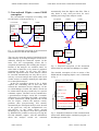
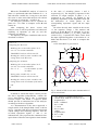
WSEAS TRANSACTIONS on ELECTRONICS
Dalibor Biolek, Jaroslav Kadlec, Viera Biolková and Zdeněk Kolka
Interactive Command Language for OrCAD PSpice via Simulation
Manager and its Utilization for Special Simulations in Electrical
Engineering
DALIBOR BIOLEK1,2, JAROSLAV KADLEC2, VIERA BIOLKOVÁ3, ZDENĚK KOLKA3
1
Dept. of EE, University of Defense, Brno, Czech Republic
2
Dept. of Microelectronics, Brno University of Technology, Czech Republic
3
Dept. of Radio Electronics, Brno University of Technology, Czech Republic
[email protected]
http://user.unob.cz/biolek
Abstract: The Interactive Command Language (ICL) significantly extends the simulation performance of
several programs based on SPICE3 standard for the analysis of electrical networks in the so-called
sequential mode, when the relatively independent tasks are run consecutively with a possibility of data
exchange. However, the ICL is not implemented in the well-known OrCAD PSpice simulation program. The
paper describes a conception of the so-called PSpice Simulation Manager (PSiM). This program implements
the ICL in OrCad PSpice. PSiM is an independently executable program which controls the OrCad PSpice,
enabling its operation in sequential mode. A powerful programming language also enables iterative runs
within the conditional loops, which can be utilized e.g. for optimization. Concrete demonstrations of PSiM
performance for circuit optimization and AC analysis of switched networks are included at the conclusion.
Keywords: - PSpice, PSiM, simulation, analysis, circuit
The PSpice Simulation Manager (PSiM),
described in this paper, is designed to control the
OrCAD PSpice in agreement with the user’s
intentions [10]. The controlling algorithm is
defined by the so-called Manager Control File
(MCF). This file should be written according to
the syntactic rules of special programming
language of the manager. This language contains,
among other things, the instructions for compiling
the ECIR (Extended Circuit File), which is a
source text for generating the PSpice Circuit File
(PCIR), commands for defining the variables, for
defining basic PSpice analyses which should be
executed, for controlling the PSpice operation, and
for receiving the simulation results, saving them in
variables, and processing them mathematically.
The paper is organized as follows: Section 2
next to this introductory part confronts the
conventional conception of PSpice analysis with
newly proposed method based on PSiM. As a
result of this comparison, benefits and sense of the
PSiM implementation are made clear. Section 3
presents the overall characteristics of the PSiM
and its language. Some relevant details are given
in Section 4. Next Sections illustrate concrete
PSiM applications, particularly the analyses which
cannot be performed within the conventional
PSpice utilization.
1 Introduction
Programs of the Spice or PSpice type are widely
used for solving various problems in electrical
engineering both at academic institutions and in
industry [1-5]. OrCAD PSpice [6] is one of
today’s well-known programs from this category.
In contrast to WinSpice [7], ISSpice4, ICAP/4 [8]
and other similar programs, it does not support the
utilization of ICL (Interactive Command
Language) [7-9] for controlling the simulation
tasks. However, this language represents a
powerful tool for operation in the so-called
sequential mode, when the simulation tasks are run
consecutively, with the ability to influence the
character of consecutive operations, depending on
the attained state of the simulation run. That is
why the OrCAD PSpice users cannot solve
problems of the following character: Successive
automated runs of different types of analyses, e.g.
AC, Transient, DC, immediately after the end of
the foregoing analysis, utilizing data from this
analysis for the current simulation run. The
consecutive modifications of model parameters,
which would depend on the results of previous
analyses. Repeated run of various simulation tasks
in the loops until the optimal behavior of circuit
model is reached.
ISSN: 1109-9445
186
Issue 5, Volume 5, May 2008
WSEAS TRANSACTIONS on ELECTRONICS
Dalibor Biolek, Jaroslav Kadlec, Viera Biolková and Zdeněk Kolka
automatically from the PSpice data files. That is
why Probe is only used post facto for user’s
manual processing of the analysis results.
2 Conventional PSpice versus PSiM
conception
The conventional conception of working with
OrCad PSpice is illustrated in Fig. 1.
Circuit File
header
netlist
commands
.end
PSpice
pspice.exe
Circuit File
header
netlist
commands
.end
results
output file
Probe files
bias point file
.........
PSpice
psp_cmd.exe
results
output file
Probe files
bias point file
.........
Probe
schematic
capture
Probe
PSiM
user
MCF
header
Fig. 1: Conventional conception of the interaction
between the user and the OrCadPSpice.
schematic
capture
The user can create the model of simulated circuit
either directly by writing the PSpice circuit file or
indirectly through the schematic capture. In the
letter case, the corresponding circuit file is
compiled automatically after running the analysis.
Results of the analyses are available either via
more kinds of data files or by means of graphical
postprocessor Probe. In any case, the above
discussed sequential mode of the analysis cannot
be executed automatically but only due to user’s
activity: user must analyze the results, and, based
on this analysis, to modify manually the input data
for a subsequent analysis.
In the new conception, shown in Fig. 2, PSiM
replaces the controlling role of user. The user
controls the simulation process indirectly via the
so-called Manager Control File (MCF) which can
be written either directly or indirectly via a special
schematic capture. The MCF can be considered as
a generalization of PSpice circuit file. It contains
instructions for controlling the PSiM. According
to these instructions, PSiM generates the circuit
file for PSpice, collects the analysis results,
performs their post-processing, and controls
automatically the subsequent analysis runs. Instead
of the pspice.exe, only the computational core
psp_cmd.exe is run which enjoys several
advantages [6]. The PSpice circuit file is generated
by PSiM directly without a necessity of using the
OrCAD schematic capture. Also the information
about the analysis results are extracted
ISSN: 1109-9445
commands
user
Fig. 2: Proposed conception of the interaction
between the user and the OrCadPSpice via PSiM.
The detailed conception of the co-action of the
PSiM and the computing PSpice core is illustrated
in Fig. 3.
Manager Control File (MCF)
header
...
set variable=1
...
assemblycir x.cir
...
Rx 1 2 variable
...
endassembly
psp_cmd.exe
run
x.out
x.cir
data from PSpice analyses
data from bias points
... ;re-defining the variables
...
... ;last command of MCF
Extended Circuit File
(ECIR)
x.dat
x.csd
x.bias
PSpice Circuit File
(PCIR)
Fig. 3: Simplified schematic of the communication
between the PSiM and the simulation program via
the Manager Control File.
187
Issue 5, Volume 5, May 2008
WSEAS TRANSACTIONS on ELECTRONICS
Dalibor Biolek, Jaroslav Kadlec, Viera Biolková and Zdeněk Kolka
program should therefore be able to work with
variables representing real numbers and to
evaluate arithmetic terms which can contain
variables, numerical constants, basic operators
(+, -, *, /, ^), braces, and some mathematical
functions. In other words, some commands
should be defined which enable the
definition/declaration of variables and the
evaluation of arithmetic terms.
The commands from the MCF are executed
step by step in a sequence that is defined in this
file. The source text of ECIR for generating the
PCIR for running an independent simulation task
is bounded by a pair of the assemblycir and
endassembly commands. In this text, the
conventional PSpice syntax can be combined with
the extended commands of the PSiM. At the
moment of processing the endassembly command,
the conventional PCIR is automatically generated,
and the computational core psp_cmd.exe is
subsequently run with the generated PCIR as a
parameter. The manager is waiting until the end of
simulation and then it finds out, on the basis of the
return code, if the simulation ran correctly. In the
case of an error, the operation of the manager is
terminated. The user can identify this error from
the output file generated.
When the simulation run is terminated
correctly, both the output file and – depending on
the character of the simulation task – other files
containing the results of individual analyses
(Transient, AC, or DC) are available, as well as
the calculated coordinates of the bias points. All
these results can be read as new variables of the
PSiM. For example, we define the VP variable and
save the value of the voltage between the nodes p
and 0 in time 10ms to this variable. This variable
can be used for defining the PCIR of subsequently
executed simulation.
• The ECIRs (Extended Circuit Files) of the
circuits being analyzed can appear in the MCF.
Thus commands should exist for the definition
of the beginning and the end of such an ECIR.
The command defining the beginning should
have a parameter indicating the file name. The
given PCIR will then be generated into this file.
The command defining the end of the ECIR
will cause the PSpice to run with the name of
the PCIR as a parameter. The PSiM will wait
for the end of the simulation and then it will
continue on the next line of the MCF.
• The PCIR contents can be modified prior to its
generation by the SiM. Recording the value of
arithmetic term in a certain place of the PCIR is
one of the alternatives. It should be possible to
write in the text of the ECIR a command for
evaluating the arithmetic term. At the moment
when the PCIR is generated, this term is
evaluated by the PSiM and its numerical value
is written into the PCIR. This method can, for
example, modify the parameters of some circuit
components in order to perform optimization.
3 Characteristics of the simulation
manager and its language
• The PSiM should be able to process the results
of already executed simulations. Thus some
commands should be defined for reading such
results. The results of certain simulations can
be saved by PSpice in the text files. The PSiM
should be able to process these files. The
commands in the MCF will enable saving such
values into user-defined variables. It will
enable subsequent work with these values.
The MCF (Manager Circuit File) serves as the
input of the PSiM. This file contains models of
simulated circuits in the PSpice language and
special commands for controlling the simulation
tasks for the PSiM. The commands for PSiM
should be unambiguously distinguishable from the
PSpice commands. The structure of the MCF
should be clear and transparent.
The MCF is thus a record of a program for the
PSiM. It was necessary to design a new, simple
programming language for the above control of
simulation tasks. The requirements for this
language were defined as follows:
• After finishing the activities of the PSiM, all
the files generated from all executed simulation
runs should be available. They are all PCIRs
and the corresponding output files, and the data
files containing the results of the simulations
which were generated by utilizing the
.SAVEBIAS or .PROBE commands. The PSiM
can perform the conservation of these files such
that it will perform their backup under modified
names after finishing the simulation run. The
• The PSiM will read the MCF step-by-step,
starting from the first line (the MCF is
processed sequentially).
• The programming language of the PSiM should
support simple mathematical computations. The
ISSN: 1109-9445
188
Issue 5, Volume 5, May 2008
WSEAS TRANSACTIONS on ELECTRONICS
Dalibor Biolek, Jaroslav Kadlec, Viera Biolková and Zdeněk Kolka
new file names will be derived from their
original names via their extension by numbers
corresponding to the order of the simulation
run.
found here, i.e. an incorrect notation of the PSiM
commands or their incorrect location. The
response to this error means terminating the MCF
processing and displaying an error message.
During the syntactic analysis, the text of the
MCF is fragmented into individual syntactic
elements (e.g. commands, comments, lines of the
generated PCIR, etc.). The syntactic elements are
represented by a data structure (class). A list of
these elements or commands is created during the
syntactic analysis. The second phase of the PSiM
operation consists in performing the commands
from this list. The PSiM activity is terminated if
the end of this list is achieved or if a command for
breaking or stopping is executed or in the case of
error (e.g. division by zero, etc.).
In the course of processing the MCF, the syntax
correctness of generated PCIRs is not checked.
This checking will be only done by PSpice itself
when processing this PCIR. Then PSpice will
simultaneously carry out the simulation.
The result of syntactic checking or the
occurrence of another error can be learned from
the return code of the psp_cmd.exe program.
When the return code is zero, the simulation was
carried out without error. If not, some error
appeared. A description of this error is given in the
output file. If such an error occurs during the
simulation, the PSiM is terminated.
• The PSiM should include commands for
program loops and chaining (the if and while
commands, known from other programming
languages) on the basis of boolean relations. By
means of boolean relations it should be possible
to compare the values of arithmetic terms, as
well as to link the boolean expressions to more
complicated units via logical operators (and, or,
negation, etc.).
• The commands for program loops and chaining
should be also placed in the text for generating
the PCIR. In this way, the user can control
which parts of the PCIR will be generated or
which parts will be repeated more times.
• The goto command can also be included among
the commands for program loops and chaining.
It serves for passing the control to the given
label (which is defined by the label command).
This whole group is called “commands for run
control”. Thanks to these commands, we can
algorithmize the evaluation of the results of
foregoing simulations and control other
simulations.
• A command should exist for including a file,
analogous to the PSpice command .INC. The
included file could also contain the commands
of the PSiM, thus it would be a MCF. That is
why the PSpice command .INC cannot be used
for such cases. Using this method, the program
controlling the PSiM could be divided into
several files, making its structure more
transparent. We can also reuse the already
generated parts of the program by this
approach.
4 PSiM variables, operators, and
commands
• The possibility of writing the comments
belongs to the natural demands on the PSiM
language. A reasonable choice is to assume the
same format as in PSpice: if the first character
on the line is *, then the content of the line
means a comment. When the comments are
written in the ECIR which generates the PCIR,
they will be also written into this PCIR.
For storing the data and its mathematical
processing, user can define PSiM variables of
several types, namely scalars, vectors, and twoand three-dimensional matrices. New variables can
be defined and evaluated on the basis of the
existing variables via operators, functions, and
commands. In addition to a common mathematical
operators and functions, known from high-level
languages, some vector and matrix operators and
functions are also implemented here which are
inspired by Matlab features.
In this Section, several basic PSiM commands
are summarized. All of them can be sorted to the
following categories. Description of their syntax is
out of the scope of this paper.
The PSiM works as an interpreter of the above
language. The PSiM operation can be divided into
two phases. The syntactic analysis of the MCF is
performed in the first step. Syntactic errors can be
• Commands for defining the variables and their
values:
set
defining scalar variable
array defining vector or matrix variable
ISSN: 1109-9445
189
Issue 5, Volume 5, May 2008
WSEAS TRANSACTIONS on ELECTRONICS
Dalibor Biolek, Jaroslav Kadlec, Viera Biolková and Zdeněk Kolka
• Commands for working with PSiM subcircuits:
beginnet beginning the PSiM netlist
endnet
ending the PSim netlist
use
calling the PSiM netlist
genTpoint generating values of specified
circuit variables for concrete
time instant
getTpoint reading the above variables to
PSiM variables
genFpoint generating values of specified
circuit variables for concrete
frequency
getFpoint reading the above variables to
PSiM variables
• Command for including source files of MCF:
include includes arbitrary source file to the
MCF
• Commands for generating the PSpice circuit
files:
assemblycir
beginning the circuit file
endassembly
ending the circuit file
The following Section provides an introductory
illustration of how to use the PSiM features for
simple optimization of transistor amplifier.
• Commands for generating the cycles and
Boolean conditions:
if..elsif..else..endif
while..endwhile
for..endfor
break
continue
label
goto
halt
5 Demonstration 1 – circuit
optimization
A simple schematic of transistor circuit is shown
in Fig. 4. Rb1 is requested to design in order to set
collector DC voltage to 8V.
bat
Vbat
Rb1
?
• Commands for interpreting conventional
PSpice commands:
beginspice
beginning PSpice code
endspice
ending PSpice code
12V
c
b
Rb2 Q1
33k
• Commands for defining and running basic DC,
AC, and Transient analyses:
defsim
defining the analysis
runsim
running the analysis
0
0
2N2222
e
Re
200
0
• Commands for generating and reading the
coordinates of DC operating point:
genbias generating the DC operating point
getbias reading it to a vector variable
Fig. 4: Example of the optimized circuit.
This task can be solved numerically via the
method of interval bisection as schematically
shown below:
• Commands for generating and reading the data
files for Probe post-processor:
genprobe generating Probe data for a
concrete analysis
getprobe reading Probe data to vector
variables
Rmin=10k, Rmax=500k, error=1m, Vreq=8V
Rb1 = (Rmin+Rmax)/2
Analysis of Vcollector
abs((Vcollector-Vreq)/Vreq)>error:
• Commands for running the so-called singlepoint DC, AC, and Transient analyses and for
reading their results:
genQpoint generating DC values of
specified circuit variables
geTQpoint reading the above variables to
PSiM variables
ISSN: 1109-9445
Rc
1.9k
Vcollector>Vreq:
yes no
yes no
Rmax = Rb1
Rmin = Rb1
end
190
Issue 5, Volume 5, May 2008
WSEAS TRANSACTIONS on ELECTRONICS
Dalibor Biolek, Jaroslav Kadlec, Viera Biolková and Zdeněk Kolka
First of all, the minimum and maximum values
Rmin and Rmax of RB1 are defined together with
the required value of collector voltage and the
acceptable error of setting this voltage.
Then the Rb1 is computed as average value of
Rmin and Rmax. For this Rb1, the bias point
computation in PSpice is performed and actual
value of collector voltage is obtained. If the
relative error is acceptable, the process of
searching Rb1 is finished. Otherwise, the actual
value of Rb1 will replace the value Rmin or Rmax,
depending on the fact if the collector voltage is
smaller or larger than the required value, and the
analysis is performed again with Rb1 as average
value of Rmin and Rmax.
The corresponding Manager Control File (MCF) is
listed below. For lucidity, the individual lines are
numbered. Note that these numbers are not part of
the MCF.
1:
2:
3:
4:
5:
6:
7:
8:
9:
10:
11:
12:
12:
13:
14:
15:
16:
17:
18:
19:
20:
21:
22:
23:
24:
25:
The couple of commands beginnet and endnet
on lines No. 5 and 12 enclose the Manager
subcircuit named ampli, which defines the PSpice
netlist of the circuit with one exception on line No.
10, where the formula #$Rb1$ is used for the
definition of resistance Rb1. The # symbol means
that the interpretation of this formula will be
provided by the PSiM, not PSpice. Then the pair
characters $ $ follow, between them is the
formula. The numerical value of this formula is
included into the generated PCIR by the PSiM. In
this case, the formula is very simple because it
contains only the Rb1 variable.
The definition of the ECIR follows (the
assemblycir command on line 13 with the pair
command endassembly on line 16). The PCIR is
generated according to this definition. It will
include the text of ampli subcircuit (due to the use
ampli command) as well as a source text of a
special single-point analysis, defined on line No.
15. This command forces PSpice to perform
single-point DC analysis with subsequent
generating DC value of the quantity, defined
within the curly braces (here v(c)), into the PSpice
output file. The command on line No. 17 reads this
value into the variable Vact, i.e. actual collector
voltage. The following commands on lines 18 to
25 contain the above discussed cycles and Boolean
conditions.
The analysis runs 10 times. The resulting value
of Rb1 is 241.3kOhms. The corresponding value
of collector voltage is 7.997 volts.
The above introductory demonstration is rather
simple, serving for acquainting with PSiM basic
features. It is true that the optimal value of Rb1
can be easily determined via convential PSpice
analyses, e.g. via stepping Rb1 within the DC
analysis. The main advantages of PSiM consist in
simulation tasks where more consecutive analyses
with data sharing are required. The following
demonstration shows such solution which cannot
be performed via the conventional PSpice
utilization.
*transistor circuit
set Rmin=10k Rmax=500k Vreq=8 err=1m
label START
set Rb1=0.5*(Rmin+Rmax)
beginnet ampli
Vbat bat 0 12V
Q c b e Q2N2222
Rc bat c 1.9k
Re e 0 200
Rb1 bat b #$Rb1$
Rb2 b 0 33k
.lib
endnet
assemblycir run
use ampli
genQpoint Qdc {v(c)}
endassembly
getQpoint Qdc Vact 1
while abs((Vact-Vreq)/Vreq)<=err
if Vact>Vreq
Rmin=Rb1
else
Rmax=Rb1
endif
goto START
endwhile
6 Demonstration 2 - AC analysis of
circuits with periodically
controlled switches
The first line represents a conventional header
of the circuit file according to common PSpice
conventions. The definitions of variables Rmin,
Rmax, Vreq and err are placed on line No. 2. The
line No. 3 is labeled as START. Line No. 4
includes a command for computing Rb1 as average
value of Rmin and Rmax.
ISSN: 1109-9445
A direct small-signal AC analysis of switchedcapacitor (SC), switched-current (SI) and other
circuits with periodically controlled analog
switches belong to well-known limitations of
Spice-compatible programs.
191
Issue 5, Volume 5, May 2008
WSEAS TRANSACTIONS on ELECTRONICS
Dalibor Biolek, Jaroslav Kadlec, Viera Biolková and Zdeněk Kolka
on the frequency response can be neglected, which
substantially simplifies the subsequent computer
analysis. This neglecting is implemented by
introducing the assumption that the input signal vin
is of the Sample-Hold (SH) character [15], e.g.
with discontinuities at switching instants. The
consistence of initial conditions and the continuity
of state variables should be ensured while
modeling the input gate of the switched circuit.
Under the above assumptions, the switched
circuit can be described in each switching phase
by linear equations (1) and (2):
A method of direct AC analysis of idealized
two-phase SC filters in PSpice has been described
in [11]. The frequency responses are acquired
neither via the repeated TRANSIENT analysis nor
by the method of multi-tone excitation [12], but
through a direct application of the conventional
AC analysis to a special model of switched circuit.
AC analysis of general linear switched circuits
while taking into consideration influences of real
phenomena, e.g. nonzero switch on-resistances,
parasitic inductances, frequency dependent
OpAmp gains, etc., is hardly applicable in Spicecompatible programs. The method described in
[11] is based on the assumption of immediate
changes of capacitor voltages at the switching
instants. That is why it cannot be used for such
cases when the lengths of transient phenomena
caused by switching processes cannot be
neglected. The new method presented below can
be used only on the assumption that the PSpice
features will be extended by the utilization of
PSiM.
Consider a linear switched circuit with twophase switching, i.e. a circuit that can be modeled
by a pair of linear circuits, separately for switching
phases 1 and 2. Let the lengths of switching phases
1 and 2 be denoted T1 and T2, respectively. Their
sum is equal to the switching period T=1/Fs, where
Fs is the switching frequency.
Exclusion of the so-called inconsistent initial
conditions (IIC) [14] is a basic assumption of
PSpice simulation of real switched circuits. The
IIC can arise in the case of idealized modeling, e.g.
when two capacitors with different initial voltages
are connected in parallel by an ideal switch with
zero on-resistance. Accepting this assumption is a
necessary consequence of the fact that the internal
algorithms of PSpice cannot resolve numerical
problems which are associated with the IIC. One
can easily avoid the IIC, e.g. by defining nonzero
on-resistances of all the switches inside the circuit.
Let us define state variables within each
switching phase of the circuit such that they are
continuous in time at instants between the
switching phases. Let the vectors of such state
variables for phases 1 and 2 be denoted x1 and x2,
respectively. In the case of avoiding the IIC, the
vectors of state variables can be compounded of
capacitor voltages and inductor currents.
As shown in [15], the behavior of real switched
networks is also affected by variations of the input
signals within the relatively short switching
phases. However, when the real phenomena are
not extremely significant, then such an influence
ISSN: 1109-9445
End of switching phase No. 1 at time t = kT+T1,
k =..0, 1, 2..
x 1 ( kT + T1 ) = A 1 x 2 ( kT ) + B 1v in ( kT + T1 ) .
(1)
End of switching phase No. 1 at time t = kT+T,
k =..0, 1, 2..
x 2 ( kT + T ) = A 2 x1 ( kT + T1 ) + B 2 vin ( kT + T ) , (2)
where A1, A2, B1, and B2 are the matrices/vectors
whose elements depend on the character of
transient phenomena in the circuit within the
corresponding switching phases.
Utilizing the theory of generalized transfer
functions [15], equations (1) and (2) can be
converted to the z-domain:
X1 = A1X 2 z −T1 / T + B1Vin,1 ,
(3)
X 2 = A 2 X1 z −T2 / T + B 2Vin,2 ,
(4)
where X1, X2, Vin,1, and Vin,2 are the z-transforms of
signals x1, x2, vin, sampled at time instants in which
the switching phases 1 or 2 are terminated.
We can conclude that the AC analysis of the
switched circuit should be accomplished in the
following consecutive steps:
1) Computing the elements of matrices and
vectors A1, A2, B1 a B2.
2) AC analysis of equations (3) and (4), utilizing
the well-known substitution z = exp(jωT).
A possible method of computing the B1 vector
implies from Eq. (1): The conventional
TRANSIENT analysis is executed during
switching phase No. 1 on the assumption of vin =
1V and under zero initial condition x2(kT). Then
the vector x1 at the end of this analysis will contain
the elements of vector B1.
192
Issue 5, Volume 5, May 2008
WSEAS TRANSACTIONS on ELECTRONICS
Dalibor Biolek, Jaroslav Kadlec, Viera Biolková and Zdeněk Kolka
at the ends of switching phases 1 and 2,
respectively [15]. The frequency responses for the
selection of output samples in phase 1 or 2,
computed in AC analysis, are defined by the
frequency dependence of the magnitude ratios and
the differences of initial phases of the
corresponding equivalent signal and the input
signal.
We select the only state variable in the circuit,
i.e. the capacitor voltage v. The matrices and
vectors of A and B types in equations (1)-(4) are
then reduced to scalars a1, a2, b1, and b2. Since the
switch in Fig. 5 separates the entire circuit from
the input signal during phase 2, the relation b2 = 0
holds and thus there is no need to compute this
quantity.
A list of the MCF is given below.
When the TRANSIENT analysis of circuit in
phase 1 is performed under the condition of vin = 0
and with state variable No. i being set to one, then
the vector x1 at the end of this analysis will contain
the elements of column No. i of matrix A1.
An analogous procedure can be repeated for
phase No. 2 in order to compute vector B2 and
matrix A2.
After computing the above vectors and
matrices, item 2) will be performed via behavioral
modeling of equations (3) and (4) and the
following AC analysis.
The sequence of PSpice simulation tasks can be
described as follows:
For k=1..2
*computing the Bk vector
Φ
Modeling the circuit within phase No. k,
vin=1V, zero initial conditions.
TRANSIENT analysis till the time Tk.
Reading the values of state variables and
saving them to the Bk vector.
vin(t)
R
C
v(t)
*computing the Ak matrix
Modeling the circuit within phase No. k,
vin=0V, zero initial conditions.
For i=1..N ;
vin(t)
v(t)
v
1e
(t )
N is the number of state
variables
t
Setting state variable No. i to one.
v
TRANSIENT analysis till the time Tk.
Φ
Reading the values of state variables and
saving them to the ith column of Ak matrix.
1
2
1
2
1
2
1
2
2e
(t )
1
2
1
2
t
kT
end
kT+T
kT+T1
end
Fig. 5: Model of SH circuit and a demonstration of
circuit waveforms.
It should be noted that PSpice cannot provide
the above algorithm independently, without the
user’s interventions. That is why a cooperation
between PSpice and PSiM is required. PSiM
should provide an automated run of the analyses
according to the above algorithm.
As a demonstration of the above approach, a
simple model of the Sample-Hold circuit is shown
in Fig. 5 together with the waveforms of input and
output voltages and switching impulses. Also the
so-called equivalent signals v1e and v2e are
indicated here. They represent the continuous-time
equivalents of discrete-time signals at time instants
ISSN: 1109-9445
1:
2:
3:
4:
5:
6:
7:
8:
9:
10:
11:
193
*AC analysis of Sample-Hold circuit
set Ron 5k fs 100k T1 0.1/fs T2 1/fs-T1
beginnet SH1
Ron 1 2 #$Ron$
Rs 2 3 10m
C 3 0 1n
Rz 2 0 100k
endnet
beginnet SH2
Rs 2 3 10m
C 3 0 1n
Issue 5, Volume 5, May 2008
WSEAS TRANSACTIONS on ELECTRONICS
Dalibor Biolek, Jaroslav Kadlec, Viera Biolková and Zdeněk Kolka
circuit file is created, the simulator is run
automatically and the corresponding analysis is
performed. The value of output voltage at time T1,
i.e. at the end of the analysis, is saved to variable b
(see line 22). This variable is labeled as b1 in
equations 1 and 3. The other circuit file
RUN2.CIR is defined on lines 23 to 28 for
computing the variable a1 (A1 matrix reduced to a
scalar). Here the input voltage is zero and the
natural response to the initial condition of state
variable V = 1V is computed. Accordingly, the
analysis of circuit file RUN3 within switching
phase 2 leads to variable a2. Equations (3) and (4)
are modeled on lines 36 to 42 by means of E-type
controlled sources. This model is then analyzed
via the AC analysis.
12: Rz 2 0 100k
13: endnet
14: defsim tran1 .TRAN 0 #$T1$ 0 #$T1/100$
+ skipbp
15: defsim tran2 .TRAN 0 #$T2$ 0 #$T2/100$
+ skipbp
16: defsim AC .AC dec 100 10 #$fs*2$
17: assemblycir run1.cir
18: Vin 1 0 1V
19: use SH1
20: runsim tran1
21: endassembly
22: getprobe b tran1 V(3) #$T1$
23: assemblycir run2.cir
24: Vin 1 0 0V
25: use SH1
26: .IC V(3) 1V
27: runsim tran1
28: endassembly
29: getprobe a1 tran1 V(3) #$T1$
30: assemblycir run3.cir
31: use SH2
32: .IC V(3) 1V
33: runsim tran2
34: endassembly
35: getprobe a2 tran2 V(3) #$T2$
36: assemblycir run4.cir
37: Vin 1 0 AC 1
38: Ec1 c1 x
+LAPLACE {V(c2)} {#$a1$*exp(-s*#$T1$)}
39: Ex x 0 value={V(1)*#$b$}
40: Ec2 c2 0
+LAPLACE {V(c1)} {#$a2$*exp(-s*#$T2$)}
41: runsim AC/nocsdf
42: endassembly
0
-10
-20
10Hz
100Hz
10KHz
DB(V(c1))
DB(V(c2))
Frequency
Fig. 6: Results of PSpice AC analysis: Amplitude
frequency response with output samples at phases
1 (V(c1)) and 2 (V(c2)).
The entire sequence of the simulation runs
takes fractions of a second on AMD Athlon™ 64
3500+ 2.21GHz, 2GB RAM with installed OrCAD
PSpice ver. 16. The resulting frequency responses
in Fig. 6 are equivalent to results obtained from a
special SPIN program [15].
The MCF starts by a header (line No. 1). The
definition of variables via set command is on line
2. The subcircuits SH1 (SH2), defined within the
lines 3 and 8 (9 and 13), model the SH circuit as
two linear circuits at phases 1 and 2. Three types
of analyses are defined on lines 14 to 16. They
will be used later in the frame of automatically
generated PSpice input files: the TRANSIENT
analysis within switching phase 1 or 2 (line 14 or
15), and the AC analysis within the frequency
range from 10Hz to the double of switching
frequency, i.e. to 200kHz (line 16). The commands
for the generation of PSpice input file RUN1.CIR
are on lines 17 to 21. This circuit file is for the
transient analysis of SH circuit within switching
phase 1, for vin = 1V and zero initial conditions.
After executing the command on line 21, this
ISSN: 1109-9445
200KHz
7 Conclusions
The PSpice Simulation Manager (PSiM),
described in this paper, is an independent
executable program which enables, with the
utilization of the so-called Manager Control File
(MCF), an effective control of the OrCAD PSpice
program. The PSiM increases the application
range of the OrCAD PSpice such that we can
program an arbitrary algorithm and combine the
194
Issue 5, Volume 5, May 2008
WSEAS TRANSACTIONS on ELECTRONICS
Dalibor Biolek, Jaroslav Kadlec, Viera Biolková and Zdeněk Kolka
[5] Dobeš, J. ‘New Features of the Algorithms for
Numerical Integration, Steady-State Analysis,
and Optimization in the Electronic Circuits
Design’, WSEAS Transactions on Systems.
2005, Vol. 12, No. 4, pp. 2322-2329.
[6] PSpice Reference Guide. Cadence Design
Systems, Inc.
[7] Smith, M. ‘WinSpice3 User’s Manual’, Ver.
from 31.8. 2008.
[8] Bürmen, A. ‘An introduction to ICAP/4’, In
Int. Workshop, Rosenheim, August 2000.
Available at
http://www.fe.uni-lj.si/spice/download/icap4.pdf
[9] System and method of providing additional
circuit analysis using simulation templates.
US Patent 7110929, Issued on September 19,
2006.
[10] Jaroš, M. ‘Simulation manager for SPICEcompatible programs’, Bachelor’s Thesis,
UMEL FEKT VUT Brno, 2007 (in Czech).
[11] Biolek, D., Biolková, V., Kolka, Z. ‘AC
Analysis of Idealized Switched-Capacitor
Circuits in Spice-Compatible Programs’, In:
Proc. of Int. Conf. CSCC’07, Greece, 2007,
pp. 1-4.
[12] Bičák, J., Hospodka, J. ‘Frequency response
of switched circuits in SPICE’, Proceedings
of ECCTD’03, Krakow, IEEE, 2003, pp. I333-336.
[13] Jaroš, M., Kadlec, J., Biolek, D.
‘Unconventional Simulation tasks in OrCAD
PSpice via Simulation Manager’, In: Proc. of
the 12th WSEAS Int. Conference on Circuits
(CSCC’08), Greece, 2008, pp.189-192.
[14] Wojcziechowski, J., Vlach, J., Opal, A.
‘Analysis of Nonlinear Networks with
Inconsistent Initial Conditions’, IEEE
Transactions on CAS-I, 1995, vol. 42, no. 4,
pp. 195-200.
[15] Biolek, D. ‘Modeling of Periodically
Switched
Networks
by
Mixed
s-z
Description’, IEEE Transactions on CAS-I,
1997, vol. 44, no. 8, pp. 750-758.
results of basic PSpice analyses (DC, AC, and
TRANSIENT). Such combining can be used for
advanced analyses of special electronic systems.
The paper demonstrates how this approach can be
used for programming atypical simulation tasks,
namely the AC analysis of real switched circuits.
Currently the version 1 of the PSiM is
completed, which works on the text file level.
Simultaneously, a graphical user’s interface is
developed
which
enables
comfortable
programming of sequential operations also for
users who do not need to master the script
language of the PSiM.
Acknowledgment
This work is supported by the Grant Agency of the
Czech Republic under grant No. 102/08/0784, by
the
research
programmes
of
BUT
MSM0021630503, MSM0021630513, and UD
Brno MO FVT0000403.
References
[1] Vladimirescu, A. ‘The SPICE book’, John
Willey&Sons, Inc., 1994.
[2] Foruzandeh, B., Farbiz, F., Khadem, M.,
Hooshmand, A. ‘Spice simulations for a
designed network that models the wp learning
algorithm’, WSEAS Transactions on Circuits,
2003, Vol. 2, No. 1, pp. 82-85.
[3] Kwon, W.-O., Park, K., Choi, P., Woo, C.-G.
‘Analog SPICE Behavioral Model for Digital
I/0 Pin Based on IBIS Model’, WSEAS
Transactions on Circuits and Systems, 2004,
Vol. 3, No. 1, pp. 1-6.
[4] Biolek, D., Biolková, V., Kolka, Z. ‘PSPICE
modelling of Buck Converter by means of
GFTs’, WSEAS Transactions on Electronics,
2006, Vol. 3, No. 2, pp. 93-96.
ISSN: 1109-9445
195
Issue 5, Volume 5, May 2008