1
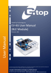
GlobalTop Technology Inc. EV-Kit User Manual (Fox series) User Manual Revision: A00 This document is the exclusive property of GlobalTop Tech Inc. and should not be distributed, reproduced, into any other format without prior permission of GlobalTop Tech Inc. Specifications subject to change without prior notice. Copyright © 2014 GlobalTop Technology Inc. All Rights Reserved. th No.16 Nan-ke 9 Rd, Science-Based Industrial Park, Tainan, 741, Taiwan, R.O.C. Tel: +886-6-5051268 / Fax: +886-6-5053381 / Email: [email protected] / Web: www.gtop-tech.com GlobalTop Technology EV-Kit User Manual (Fox series) Document # Ver. A00 Version History Title: Subtitle: Doc Type: Revision A00 EV-Kit User Manual(Fox series) GPS Module Datasheet Date Author 2014-01-22 MaxNi Description Preliminary This document is the exclusive property of GlobalTop Tech Inc. and should not be distributed, reproduced, into any other format without prior permission of GlobalTop Tech Inc. Specifications subject to change without prior notice. Copyright © 2014 GlobalTop Technology Inc. All Rights Reserved. 2 GlobalTop Technology EV-Kit User Manual (Fox series) Document # Ver. A00 3 Table of Contents Version History .......................................................................................................................... 2 Table of Contents ....................................................................................................................... 3 Caution ..................................................................................................................................... 4 Packing Contents ....................................................................................................................... 5 1. Introduction .......................................................................................................................... 6 2. Function Description .............................................................................................................. 7 2.1 Hardware overview....................................................................................................... 7 3. Operating Instruction ............................................................................................................. 8 3.1 Setting Fox-1EV-Kit before Testing ............................................................................ 8 3.1.1 Mounting the boards onto the Main board ............................................................... 8 3.1.2 Fox-1Function Testing .............................................................................................. 9 3.2 Setting Fox-2EV-Kit before Testing .......................................................................... 11 3.2.1 Mounting the boards onto the Main board ............................................................. 11 3.2.2 Fox-2Function Testing ............................................................................................ 12 4. Software Usage.....................................................................................................................14 4.1 System requirement ................................................................................................... 14 4.2 USB Driver and Smart GPS Viewer ............................................................................ 14 4.3 Install the USB Driver and Microsoft Framework ...................................................... 15 5. Trouble-shooting ..................................................................................................................17 5.1 Problem with Setup .................................................................................................... 17 5.2 Concerning Poor GPS Signal ....................................................................................... 18 This document is the exclusive property of GlobalTop Tech Inc. and should not be distributed, reproduced, into any other format without prior permission of GlobalTop Tech Inc. Specifications subject to change without prior notice. Copyright © 2014 GlobalTop Technology Inc. All Rights Reserved. GlobalTop Technology EV-Kit User Manual (Fox series) Document # Ver. A00 Caution Global Positioning System (GPS) is the property of American Ministry of National Defense; they are fully responsible for the preciseness and maintenance of the system. Any changes they have implemented to the system in the future may enhance or deteriorate the effectiveness and performance of the received GPS data. The GPS signal might be cut-off or become seriously weakened if EV-kit were operated inside any infrastructures such as buildings, tunnels, or nearby any huge objects and/or obstruction. The positioning will function again when it receives clear GPS signals (works best under open sky). To avoid damaging the intricate electronic components and circuitry, please do not place EV-Kit directly under the sun for long periods of time. To avoid unexpected E-compass behavior, please do not place EVB in proximity to any magnetic material. This document is the exclusive property of GlobalTop Tech Inc. and should not be distributed, reproduced, into any other format without prior permission of GlobalTop Tech Inc. Specifications subject to change without prior notice. Copyright © 2014 GlobalTop Technology Inc. All Rights Reserved. 4 GlobalTop Technology EV-Kit User Manual (Fox series) Document # Ver. A00 Packing Contents User Manual / Software Application Program* CP210X USB Bridge VCP driver Smart GPS Viewer tool with user manual EV-Kit user manual *The software and documents will only be delivered by E-mail. Please contact with your dealer. USB Cable The EV-Kit contains Main Board, GPS Module Board and MEMS sensors Board External Antenna This document is the exclusive property of GlobalTop Tech Inc. and should not be distributed, reproduced, into any other format without prior permission of GlobalTop Tech Inc. Specifications subject to change without prior notice. Copyright © 2014 GlobalTop Technology Inc. All Rights Reserved. 5 GlobalTop Technology EV-Kit User Manual (Fox series) Document # Ver. A00 1. Introduction The main purpose of this EV-Kit is to simplify the evaluation process to our GPS modules and to help testers operate our products with convenience and ease. Fox-Series EV-Kit is suitable for use in combination with selected GlobalTop modules such as Fox-Series (Fox-1, Fox-2) and recommended MEMS Sensors. This device communicates with computer via USB, and must be used in conjunction with Smart GPS Viewer software for data reading, information display, GPS data recording such as satellites’ status, time-to-first-fix (TTFF), date and time. EV-Kit Features: Main Board A GPS module Board A Sensor Board USB communication port (main communication port with PC for NEMA code) Power LED Indicator (Red) 3D Fix LED Indicator (Blue) 1PPS LED Indicator (Green) Programmable GPIO This document is the exclusive property of GlobalTop Tech Inc. and should not be distributed, reproduced, into any other format without prior permission of GlobalTop Tech Inc. Specifications subject to change without prior notice. Copyright © 2014 GlobalTop Technology Inc. All Rights Reserved. 6 GlobalTop Technology EV-Kit User Manual (Fox series) Document # Ver. A00 7 2. Function Description 2.1 Hardware overview The EV-kit is consisted of three boards: the Main board, the MEMS sensor board and GNSS Module board. The MEMS sensor board and GNSS Module board are the daughter boards which are to be mounted onto the Main board as shown below in Figure 1. 2. MEMS Sensor Board 3a. GNSS Module Board 3b. GNSS Module Board (For Fox-1 module) (For Fox-2 module) 1. Main Board Figure 1. EV-Kit boards USB communication port (USB1) (For power input &data transmission) Main Board power switch (SW1) Reset Push-bottom (S1) Power on/off This document is the exclusive property of GlobalTop Tech Inc. and should not be distributed, reproduced, into any other format without prior permission of GlobalTop Tech Inc. Specifications subject to change without prior notice. Copyright © 2014 GlobalTop Technology Inc. All Rights Reserved. GlobalTop Technology EV-Kit User Manual (Fox series) Document # Ver. A00 3. Operating Instruction For Fox-1 user 3.1 Setting Fox-1EV-Kit before Testing 3.1.1 Mounting the boards onto the Main board Step 1. Install MEMS sensor Board and GNSS Board onto Main Board Mount MEMS board on the left hand corner of the main board. Mount Fox-1 board on the right hand side of the main board. Ensure that the boards are on the correct placement orientation. Refer to Fig.2 2. MEMS Sensor Board 3a. GNSS Module Board (For Fox-1 module) 1. Main Board Figure 2. EV-Kit boards This document is the exclusive property of GlobalTop Tech Inc. and should not be distributed, reproduced, into any other format without prior permission of GlobalTop Tech Inc. Specifications subject to change without prior notice. Copyright © 2014 GlobalTop Technology Inc. All Rights Reserved. 8 GlobalTop Technology EV-Kit User Manual (Fox series) Document # Ver. A00 3.1.2 Fox-1Function Testing Preparation for the power and data communication Step 1. Connecting USB port Connect the USB cable between PC and EV-Kit. The USB cable is used to power the EV-Kit and to transfer communication data with PC. Power LED Indicator (D1) light will be on. LED_D15 LED_D13 LED_D14 LED_D2 LED_D1 USB communication port (USB1) Figure 3. EV-Kit boards (For power input &data transmission) Main Board power switch (SW1) Power on/off This document is the exclusive property of GlobalTop Tech Inc. and should not be distributed, reproduced, into any other format without prior permission of GlobalTop Tech Inc. Specifications subject to change without prior notice. Copyright © 2014 GlobalTop Technology Inc. All Rights Reserved. 9 GlobalTop Technology EV-Kit User Manual (Fox series) Document # Ver. A00 Step 2. Turn on the power Turns on power from the SW1 switch. This will turn on the GNSS Board and MEMS senor board: LED indicators –D2 & D15 (red) stay on. Before the receiver module gets 3D_FIX: LED Indicator (D14) blue starts to flash. Once the receiver module gets 3D_FIX: LED Indicator (D14) turns off and Indicator (D13) green starts to flash. *The flashing of D3 is controlled by the 1PPS signal. The 1PPS status can be re-defined, please contact GlobalTop Sales representatives. This document is the exclusive property of GlobalTop Tech Inc. and should not be distributed, reproduced, into any other format without prior permission of GlobalTop Tech Inc. Specifications subject to change without prior notice. Copyright © 2014 GlobalTop Technology Inc. All Rights Reserved. 10 GlobalTop Technology EV-Kit User Manual (Fox series) Document # Ver. A00 For Fox-2 user 3.2 Setting Fox-2EV-Kit before Testing 3.2.1 Mounting the boards onto the Main board Step 1. Install MEMS sensor Board and GNSS Board onto Main Board Mount MEMS board on the left hand corner of the main board. Mount Fox-2 board on the right hand side of the main board. Ensure that the boards are on the correct placement orientation. Refer to Fig.3 2. MEMS Sensor Board 3b. GNSS Module Board (For Fox-2 module) 1. Main Board Figure 3. EV-Kit boards This document is the exclusive property of GlobalTop Tech Inc. and should not be distributed, reproduced, into any other format without prior permission of GlobalTop Tech Inc. Specifications subject to change without prior notice. Copyright © 2014 GlobalTop Technology Inc. All Rights Reserved. 11 GlobalTop Technology EV-Kit User Manual (Fox series) Document # Ver. A00 3.2.2 Fox-2Function Testing Preparation for the power and data communication Step 1. Connecting USB port and Antenna Connect the USB cable between PC and EV-Kit. The USB cable is used to power the EV-Kit and to transfer communication data with PC. Power LED Indicator (D1) light turns on. Connect an active/passive antenna to Antenna Connector Antenna Connector LED_D8 LED_D7 LED_D6 LED_D2 LED_D1 USB communication port (USB1) Figure 5. EV-Kit boards (For power input &data transmission) Main Board power switch (SW1) Power on/off This document is the exclusive property of GlobalTop Tech Inc. and should not be distributed, reproduced, into any other format without prior permission of GlobalTop Tech Inc. Specifications subject to change without prior notice. Copyright © 2014 GlobalTop Technology Inc. All Rights Reserved. 12 GlobalTop Technology EV-Kit User Manual (Fox series) Document # Ver. A00 Step 2. Turn on the power Turns on power from the SW1 switch. This will turn on the GNSS Board and MEMS senor board: LED indicators –D2 & D8 (red) stay on. Before the receiver module gets 3D_FIX: LED Indicator (D6) blue starts to flash. Once the receiver module gets 3D_FIX: LED Indicator (D6) turns off and Indicator (D7) green starts to flash. *The flashing of D3 is controlled by the 1PPS signal. The 1PPS status can be re-defined, please contact GlobalTop Sales representatives. This document is the exclusive property of GlobalTop Tech Inc. and should not be distributed, reproduced, into any other format without prior permission of GlobalTop Tech Inc. Specifications subject to change without prior notice. Copyright © 2014 GlobalTop Technology Inc. All Rights Reserved. 13 GlobalTop Technology EV-Kit User Manual (Fox series) Document # Ver. A00 4. Software Usage 4.1 System requirement PC: IBM, Pentium or above or compatible PC Operation system: Windows 7/XP/2003/Vista USB driver: CP210xVCPInstaller.zip GPS viewer: Smart GPS viewer.exe Microsoft Framework 3.5 version or latest version. 4.2 USB Driver and Smart GPS Viewer Please double check if you have the correct USB driver and Smart GPS Viewer before you proceed to the next step. If an incorrect driver is installed, your EV-Kit will not work properly! If you have purchased the EV-Kit, please make sure you have downloaded CP210xVCPInstaller.zip file and proceed to the next section: [4.3 Install the USB Driver]. EV-kit USB Driver Download From Silicon Labs Web-side (CP210x USB to UART Bridge VCP Drivers) http://www.silabs.com/products/mcu/Pages/USBtoUARTBridgeVCPDrivers.aspx Smart GPS Viewer Download For Fox-1 http://www.gtop-tech.com/en/product/Fox-1-Module/GPS_Modules_Fox-1.html For Fox-2 http://www.gtop-tech.com/en/product/Fox-2-Module/GPS_Modules_Fox-2.html This document is the exclusive property of GlobalTop Tech Inc. and should not be distributed, reproduced, into any other format without prior permission of GlobalTop Tech Inc. Specifications subject to change without prior notice. Copyright © 2014 GlobalTop Technology Inc. All Rights Reserved. 14 GlobalTop Technology EV-Kit User Manual (Fox series) Document # Ver. A00 4.3 Install the USB Driver and Microsoft Framework Please extract the file [CP210xVCPInstaller.zip] and double click [CP210xVCPInstaller.exe] to begin driver installation as shown in the figure below. Click [Install] as the figure show below. After the installation is complete, you may need to restart your computer, please follow the instructions on screen to restart your computer. After the computer has rebooted and ready, from the desktop right mouse click on <My Computer>, and from the drop down menu, select <Manage>, as in figure shown below. This document is the exclusive property of GlobalTop Tech Inc. and should not be distributed, reproduced, into any other format without prior permission of GlobalTop Tech Inc. Specifications subject to change without prior notice. Copyright © 2014 GlobalTop Technology Inc. All Rights Reserved. 15 GlobalTop Technology EV-Kit User Manual (Fox series) Document # Ver. A00 Click on <Device Manager>, and expand the list of <Ports (COM &LPT)>. Check to see if a device named <Silicon Labs CP210x USB to UART Bridge (COM#)> is present. If yes, then EV-Kit is now ready for use. Refer to the figure below. In this example, the virtual COM port “COM9” is assigned to this established connection to the EV-Kit. You will need this information in the later step. Install Microsoft Framework 3.5 version or latest version Install GPS Viewer Software After completed the installation, please go forward to GPS Viewer Software usage section in 4.4. This document is the exclusive property of GlobalTop Tech Inc. and should not be distributed, reproduced, into any other format without prior permission of GlobalTop Tech Inc. Specifications subject to change without prior notice. Copyright © 2014 GlobalTop Technology Inc. All Rights Reserved. 16 GlobalTop Technology EV-Kit User Manual (Fox series) Document # Ver. A00 17 5. Trouble-shooting 5.1 Problem with Setup Problem Cannot find GPS device Possible Cause USB was not setup properly. (1) USB was not setup properly. (2) COM Port or Baud rate value is incorrect. No NMEA data or GPS signals Poor GPS Signal Reception (1) If it is used inside a vehicle, the anti-sunscreen film on the windshield may interfere and weaken the GPS signal reception. (2)When the vehicle is traveling through an area with dense overhead canopy: such as forest, buildings, open tunnels etc. Trouble shooting Check to see if the USB connection was connected properly, and make sure that the device is receiving enough power through the USB cable (Red LED should light up continuously). (1) Check to see if the USB connector to PC or EV-Kit is tightly connected. (2) Double check to see if the proper COM Port and Baud rate value was selected. For both problems, please connect the external antenna to the EV-Kit, and place the antenna on the roof top to improve signal reception. Note: If the above troubleshooting advice does not solve your problems, please send it back to us for testing and repair. This document is the exclusive property of GlobalTop Tech Inc. and should not be distributed, reproduced, into any other format without prior permission of GlobalTop Tech Inc. Specifications subject to change without prior notice. Copyright © 2014 GlobalTop Technology Inc. All Rights Reserved. GlobalTop Technology EV-Kit User Manual (Fox series) Document # Ver. A00 18 5.2 Concerning Poor GPS Signal It is possible to have GPS signal reception difficulties under the following situations: Inside a tunnel, where GPS signal is blocked. Underneath an infrastructure (like beneath a bridge), where GPS signal is blocked. Inside a building, where GPS signal is blocked. Next to tall buildings, where GPS signal is weakened. Underneath forests or any other kinds of canopy where GNSS signal is weakened. If you use EV-Kit inside a car with anti-sunlight windshield film, the GPS signal will be severely degraded, and may result in no GPS reception. GPS satellite is a property of United States Army. Sometimes they will tune-down the accuracy for unknown reasons. In such cases, the GPS position may not be as accurate. This document is the exclusive property of GlobalTop Tech Inc. and should not be distributed, reproduced, into any other format without prior permission of GlobalTop Tech Inc. Specifications subject to change without prior notice. Copyright © 2014 GlobalTop Technology Inc. All Rights Reserved.