1
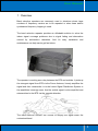
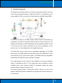
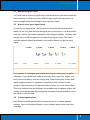
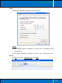
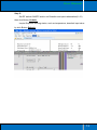
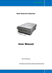
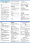
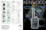
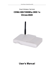
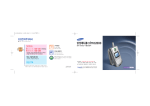
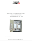
User Manual
User Manual
Wide Band Booster (30dBm)
2012 February
Information in this manual is subject to change without notice
1 User Manual
Table of Contents
1 Overview ................................................................................................................. 3 2 System Diagram ...................................................................................................... 4 3 Technical Specification ........................................................................................... 5 4 Features ................................................................................................................... 6 5 Applications Example ............................................................................................. 6 6 7 5.1 Minimum Signal Levels ............................................................................... 8 5.2 How to check your signal levels................................................................... 8 5.3 Custom Applications .................................................................................... 8 5.4 Isolation and Separation ............................................................................... 9 Production Operation .............................................................................................. 9 6.1 Notices .......................................................................................................... 9 6.2 Installation .................................................................................................. 10 6.3 Operation & Software ................................................................................ 11 Frequency Ask Question ....................................................................................... 14 Important Notice:
Don’t power on Power supply for repeater before donor and
service antenna connects to repeater.
2 User Manual
1 Overview
Band selective repeaters are commonly used in situations where large
numbers of frequency carriers are to be repeated or when base station
synthesized frequency hopping is used.
The band selective repeater provides an affordable solution to solve the
indoor signal coverage problems due to signal fading and attenuation
caused by architecture obstacles. And it’s easy installation and
maintenance can help carrier get fast return.
The repeater is working as a relay between the BTS and mobiles. It picks up
the strongest signal from BTS via the Donor Antenna, linearly amplifies the
signal and then retransmits it via the Indoor Signal Distribution System to
the weak/blind coverage area. And the mobile signal is also amplified and
retransmitted to the BTS via the opposite direction.
The band selective function can choose to amplify the signal within the
customized band.
3 User Manual
2 System Diagram
The signal from the base station is received via the repeater Donor antenna
and is then forwarded through a duplex filter (DPX), is amplified in a low
noise amplifier (LNA), and enters the band selective amplifier board (BSA).
The first mixer stage on the BSA amplifier board, which is controlled by a
synthesizer, converts the received frequency down to the IF frequency. The
signal is then filtered by a SAW band-pass filter and amplified before it is fed
to the second mixer stage, controlled by the same synthesizer as the
previous one, for converting back to the original frequency.
The SAW filter can be either fixed or adjustable depending on the BSA
board used. If the BSA board has fixed band width, this SAW filter is fixed
and selected for the current band width. If the BSA board has adjustable
band width, the SAW filter can be software changed.
The output signal from the mixer is then amplified in the power amplifier,
which is controlled by the CU. The output gain can be reduced to avoid
instability due to poor antenna isolation. If necessary, reduce the output
power to keep it under a maximum level.
The output signal passes a duplex filter (DPX), before it is fed to the
repeater MS antenna which retransmits the signal at the same frequency to
the aim areas.
4 User Manual
3 Technical Specification
Specification
Items
Uplink
Downlink
Network(Customized)
869~894MHz
824~849MHz
Gain
≥ 85 dB
≥ 85dB
Output Power
27dBm
30dBm
Gain Adjustment Range
≥ 30 dB
Gain Adjust precision
0~10dB/±1dB#10~20dB/±1.5dB#20~31dB/±2dB
ALC Scope
≥ 20dB
In-Band Ripple
≤ 3 dB
Out-of-Band Suppression
±600kHz > 20dB,
±1MHz > 46dB, ±5MHz > 50dB, ±10MHz > 52dB
I/O Impedance
50 Ω
VSWR
≤1.5
Load VSWR Tolerance
20:1
Noise Figure
≤ 8 dB
Inter-modulation Attenuation
-40dBc
Spurious Emission
≤-36dBm(9KHz~1GHz)/≤-30dBm(1~12.75GHz)
System Delay
≤ 0.5μs
Max Input Power Level(1minute)
-10dBm
RF Connector
N-Type (Female)
Operating Temperature
-15~ +55 °C
Power Supply(Customized)
AC100~240V
Power Supply Socket(Customized)
Connector Type B
Power Consumption
45W
Dimension (mm)
245mm×190mm×75mm
Weight(kg)
4.5kg
Shipment Dimension (mm)
370mm×350×160mm
Shipment Weight(kg)
6.0kg
Power
Indication
LED
Alarm
Access Type
Monitor
Monitor Parameters
Control Parameters
60Hz
Light when power supply on
Light when alarm happens(Low input signal, Vswr, door
etc)
- Local Control through Comm. port
- SMS/GPRS: through wireless Modem
Alarms, PA, VSWR, System Over–Temp, UL/DL Output
Power, UL/DL Gain
- ATT, Over-Temp, Gain
- Thresholds: System PA, Output Power
- Alarm Enable
5 User Manual
4 Features
z
All-in-One design, easy to install with light weight and small size
z
High system gain
z
Intermediate frequency filtering is used to implement out of band
suppression.
z
Smart Automatic Level Control (ALC) ensures output level stable and
adjustable continuously
z
Gain adjustment of uplink and downlink; gain adjust step is 1dB and
the adjust scope is 30dB.
z
Unique color LEDs to indicate power supply and signal level of uplink
and downlink
z
RS-232 port provides a link to a notebook for local supervision or
GMS SMS(Optional)
to communicate with the NMS (Network
Management System) that can remotely supervise repeater’s working
status and download operational parameters to the repeater.
z
Designed for all outdoor installation – waterproof, damp-proof and
Omni-sealed (IP65)
5 Applications Example
6 User Manual
1) The signal strength (includes donor antenna) from donor BTS must be 5dB
larger than from neighbor BTS lists and signal level>-50dBm, so the
repeater can amplifier in high efficiency with full output power.
2) The donor antenna should have line of sight (LOS) with the BTS antenna.
If the signal strength is adequate, LOS may in some cases not be
necessary.
3) Donor antenna gains are typically 9 to 14 dB, and have a horizontal and
vertical beam width of less than 30° to correctly select the donor BTS.
4) There is large physical separation between the antennas in order to
prevent degradation of signal quality and risk of oscillation (Antenna
isolation). Ways to achieve this can be usage of highly directional
antennas with good front-to-back interference ratio or external shielding
between the antennas (For example, your building has a metal roof and
you install the Donor antenna above the roof and the Coverage antenna
below the roof.). Another option is to use a Frequency Shifting Repeater or
ICS repeater.
7 User Manual
5.1
Minimum Signal Levels
You must have a minimum signal level in the place where you would install the
Donor antenna. Failure to provide sufficient input signal will only result in a
poor coverage inside the building for this repeater system.
5.2
How to check your signal levels
To check your signal levels, use the phone in the place where antenna be
install (on the roof) and observe the signal bars on the phone. It is also helpful
to be on a call for immediate registration of the signal/reception. Carefully walk
around the roof with the phone to see where the signal is best. The Donor
(outside) antenna should be placed in the location where you get the most
signal.
5 Bars
4 Bars
3 Bars
2 Bars
1 Bars
NOKIA
NONE
>-85dBm
-85~-90dBm
-90~-95dBm
-95~-100dBm
Anycall
>-85dBm
-85~-90dBm
-90~-95dBm
-95~-100dBm
-100~-105dBm
Motorola
>-80dBm
-80~-90dBm
-90~-95dBm
-95~-100dBm
-100~-105dBm
Simens
NONE
>-70dBm
-70~-80dBm
-80~-90dBm
-90~-100dBm
Errison
>-75dBm
-75~-85dBm
-85~-90dBm
-90~-95dBm
-95~-105dBm
SAGEM
>-80dBm
-80~-90dBm
-90~-95dBm
-95~-105dBm
-110~-105dBm
It is important to investigate and understand what is causing your reception
difficulties. If your building is made of concrete, steel, steel roof, copper roof,
brick, aluminum siding, concrete roofing tiles, metal roofing tiles or any other
signal stopping material, a repeater is usually the ideal solution for your
situation. Signal outside is 3-5 bars and falls off when you enter the building.
This is an indicator that the building is the problem and a repeater system will
usually solve that problem by bringing that reception from the outside to cover
the inside of your building.
5.3
Custom Applications
Most homes or buildings are easily covered by one of our base repeater
systems. Some buildings are larger or have multiple areas inside that need
coverage.
8 User Manual
You may need longer cables, more than 2 coverage antennas or other items in
order to fully cover your building. We can make (almost) any cable length and
can help design a system that fits your application.
5.4
Isolation and Separation
Isolation refers to the proper distance or separation needed to keep the Donor
antenna signal pattern and the Coverage antenna signal pattern away from
each other.
Isolation becomes particularly problematic when Omni-directional antennas
are used for both the Donor and the Coverage antennas. Since these
antennas transmit in a circle (or more accurately a sphere) it is very easy for
these spheres to overlap and thus negate the repeater system.
6 Production Operation
6.1
Notices
Follow below safety items carefully before installation, implementation,
maintenance and operation for this product
) Repeater amplifies BTS uplink and downlink signal, it can extend BTS
coverage area in downlink, but also effect BTS receive sensitivities in
uplink.
) BS and MS port must be connected to donor antenna and service antenna
when powers supply on; otherwise the equipment will be damage for long
term use.
) When use repeater for outdoor, the distance between donor antenna and
service antenna must be >20metes, otherwise the repeater will be damage
because isolation problem for long term use.
) Donor antenna need to be lighting proof and lighting rod need to be install
for donor antenna installation pole outside
) Check input power, require input power less than maximum input power of
repeater, otherwise the repeater cannot work well.
) Keep clear for label and indicator on surface of repeater to be identified.
9 User Manual
6.2
Installation
Installing a repeater system is really quite simple. The most difficult task in
installing the system is running the cable and does connectors.
Step 1: Start by taking your phone up to the roof or other location outside
to find where the signal is strongest.
Step 2: Temporarily mount the Donor (outside) antenna in that location.
You may need to adjust and move the antenna later.
Step 3: Run coaxial cable into the building to a convenient location where
you can also get standard 100~220VAC power for the repeater.
Step 4: Place the repeater in that location and connect the coaxial cable to
the Donor Side of the repeater and the donor antenna.
Step 5: Mount your coverage (inside) antenna in a productive location.
You may need to adjust or move the antenna later.
Step 6: Connect coaxial cable between the coverage antenna and the
repeater output port.
Step 7: Power up the system and check for signal inside the building. If
needed, tune system by moving and or pointing the Donor and Coverage
antennas until they get the most signal possible.
Step 8: Secure all antennas and cables, securely mount the repeater and
clean up the installation.
10 6.3
User Manual
Operation & Software
Port
Connection
Usage
BTS
Connect to Donor antenna
Receive BTS signal source
MS
Connect to Service antenna
Retransmitted signal to target coverage area
LAN
Connect to Laptop LAN port
Set and inquire repeater parameter and status
PWR
Power Supply indicator
LED ON when AC power on
ALARM
Alarm indicator
LEN ON when alarm happens for VSWR, low
input power etc.
Step 1:
Connect repeater LAN port to laptop LAN port via attached LAN cable;
Step 2:
Open laptop network connection
11 User Manual
Step 3:
Set laptop IP address and Mask as following picture.
Notice:
1) The repeater default IP address is 192.168.1.160, and subnet mask is
255.255.255.0
2) The laptop ip address be set like 192.168.1.X, X=1~159 and 161~254
Step 4:
Run IE, and input IP: 192.168.1.160, then Enter
12 User Manual
Step 5:
Set RF switch ON/OFF and/or set Downlink and uplink attenuation(0~31)
then click Button Submit;
Inquire Repeater working status, such as temperature, downlink input value
by click Button Refresh;
13