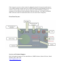
1
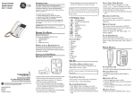
NEGATIVE PRESSURE ENCLOSURE
MONITOR UNIT
HS-EM1
USER MANUAL
SMH Products Ltd
South Shields
Document Number
Approved
Date
Revision Number
HS-EM1 – User Manual
20-03-15
R1
The Harley Scientific Negative Pressure
Enclosure Monitor Unit HS-EM1
User Manual
Introduction:
The Harley Scientific Negative Pressure Enclosure Monitor Unit HS-EM1 is a device
for monitoring the air-pressure relative to ambient in a permanent or temporary
enclosure where it is desirable to maintain a small negative pressure difference in
order to prevent the egress of undesirable gasses, vapours, or particulates from the
enclosure.
The device features an organic light emitting diode (OLED) display to inform an
operator as to the working status of the unit. A keypad allows data entry of, for
instance, alert thresholds. An audible annunciator is also included.
Three Light Emitting Diode (LED) status indicators: Red to indicate that the unit is
powered; Green and Blue indicate status of the internal Bluetooth module.
A set of volt-free changeover relay contacts are available for connecting either an
external remote sounder, or an external telephone dialler.
The HS-EM1 is principally a monitoring device however external equipment such as
booster air handling units may be indirectly operated by means of a set of volt-free
changeover relay contacts available at a male connector on the front panel.
Wired communication with the unit may be executed by means of a USB connection
to a connected lap-top computer. Also the unit includes a wireless (Bluetooth) module
allowing communication to a remote printer unit.
The unit is powered form a mains (line) source and is tolerant of wide variation in the
supply voltage. A convenient aperture is included for storing the mains cable lead
when not in use.
In normal operation, the unit is installed outside the monitored enclosure. A smallbore tube connects the unit to the negative pressure enclosure by inserting its distal
end through a suitable aperture in the enclosure. An operator adjustable programmed
“Alert” set point initially requires setting to an appropriate pressure differential value
(in Pascals), which, if crossed, activates the audio annunciator and causes both relays
to switch state. The date and time of such an event is internally logged for later
analysis.
Please note that when switching on the unit for the first time, and with no
pressure present, an ALERT condition is likely to be asserted and this can be
immediately accepted by pressing the Return Key.
Starting Up:
Choose a suitable location to position the unit close to an available mains power
supply, and within 10m (max) of a suitable place to pass tubing into the enclosure to
be monitored. Connect the 6mm OD tubing to the negative input push-fit connector
on the unit. Ensure that the distal end of the tubing within the enclosure is positioned
so that it cannot be obstructed, and preferably pointing downwards to prevent debris
from entering it. Ensure that there is no potential for excessive leakage around the
tubing’s entry point into the enclosure.
Insert the power lead into the receptacle, and connect the other end of the power lead
to a suitable supply (100 – 240V~).
Switch the unit ON by depressing the small rocker switch below the power entry
connector.
The audible alarm will sound for several seconds. If the measured pressure is below a
previously set alert threshold, it will persist, and must then be silenced by pressing the
RETURN KEY.
It is assumed that the unit has already been pre-set1 using a computer communicating
through the USB port with the following parameters:
ALERT set to 20Pa and the mode is NOT FIXED
TIME and DATE
Language ENGLISH
The OLED display screen will show:-
Approximately every ten seconds the display will blink and show:-
This confirms that the current data has been saved to memory.
1
See Harley Scientific EM1 Software Guide for instructions how to use the unit with
a computer.
Adjusting the ALERT Set-Point:
The ALERT set point can be adjusted by a suitably qualified operator by using the UP
and DOWN buttons.
To raise the set point under normal operation, repeatedly press the UP
until the desired value is displayed on the OLED.
Conversely, to lower the set point press the DOWN
key
key
The set point can be adjusted in the range 0 to 60Pa.
Note: Using the EM-1’s PC software application, it is possible to lock out the keypad,
preventing unauthorised modification to the alert levels.
Action in an ALERT condition:
In the event that the pressure within the enclosure drops below the ALERT set point:
The sounder will activate;
The relay contacts accessed through the External Sounder/Remote Dialler
Connector will change state;
The relay contacts accessed through the Air Handling Unit Connector will
change state.
Responding to an ALERT condition:
Operation of the ACCEPT button
will result in:
The sounder will be silenced;
The relay contacts accessed through the External Sounder/Remote Dialler
Connector will return to the original state;
The relay contacts accessed through the Air Handling Unit Connector will
remain in their changed state.
Subsequent elevation of the pressure within the enclosure above the ALERT set point
will result in:
The sounder continuing to activate until ACCEPT pressed (unless already
pressed);
The relay contacts accessed through the External Sounder/Remote Dialler
Connector will continue in the change state until ACCEPT pressed (unless
already pressed);
The relay contacts accessed through the Air Handling Unit Connector will
change state reverting back to the normal condition.
Shutting Down:
When the monitoring process ceases to be required, simply switch the unit OFF by
depressing the small rocker switch below the power entry connector.
Using the Optional Bluetooth Printer:
A small hand-held printer may optionally be provided to offer hard copy of the unit’s
event log.
The unit is designed to connect using the Bluetooth communications protocol.
To print:
Turn the printer ON;
Simultaneously PRESS the PRINTER key AND the ACCEPT key;
The OLED displays the message:-
When it finds the printer:-
Within the next five seconds, the printer will respond, and print the most recent 32
events in the log.
During the print operation, the Blue LED will flash to indicate successful
connectivity.
Using the External Relay Connectors:
Common
N/O
All three volt free contacts from the respective relays associated with
an external “Air Handling Unit” and “External Sounder” (which may
also be used to attach to an external Telephone Dialler), are available
at a pair of “Bulgin” connectors. The wiring of the connector is as
N/C
shown in the diagram. In normal operation the relays are de-energised
The maximum ratings for these relay contacts are 240V~ and 3A (including
surge). Note that these connectors are not internally fused.
Calibration:
The HS-EM1 internal pressure sensors are factory calibrated, and in normal operating
conditions no adjustments are necessary. However there is a requirement for the
sensors to be checked, and if necessary, re-calibrated on an annual basis. To remind
the user of this requirement, a message “Not Calibrated” will be displayed on the
OLED display after twelve months from shipment.
In addition, this screen will display the “Not Calibrated” message in the unlikely
event that an internal fault has developed within the unit. If this
happens, press
the Return Key to clear it.
Warnings:
Warning: The voltages used in this unit can cause electric shock. The unit
should not be placed in a position where it could be immersed in water.
Warning: It is possible to apply external voltages to this unit that could cause
electic shock. Attaching external equipment to the Air Handling Unit relay
connector, or the External Sounder/Autodialler relay connector, must only be
performed by a suitably qualified person. The maximum voltage that can be
applied to any of the pins on these connectors must not exceed 240V~ when
measured relative to the unit’s earth connection. Maximum Current is 3A.
Troubleshooting:
The HS-EM1 has been designed to be easy to use, however, some simple problems
may arise.
The message “Positive Pressure” on the display indicates that the tube connection
from the enclosure has been fitted to the wrong port. Alternatively, it may have been
fitted correctly but the protective bung has not been removed from the other port.
The unit will operated with the specified accuracy provided that the total length of
tubing (ie the sum of the length of tubing from the enclosure together with any tubing
connected to the reference port) does not exceed 5m. If it is desired to use lengths of
tubing in excess of this, then it is advisable to connect using larger bore tubing for the
main lengths and a suitable tubing size adaptor close to the HS-EM1.
In the unlikely event that the mains input fuses are blown, after examining the unit for
water ingress, replace with a pair of new 3.15 AMP 20mm fuses. The fuses are
located in a draw within the IEC Mains Input connector/switch unit.
If the target air pressure values cannot be adjusted using the front panel push-buttons,
it is possible that the unit has been set to FIXED mode to prevent unauthorised access
to these controls. This status can only be returned to NOT FIXED by attaching a
computer to the USB port and running the dedicated software. (See Harley Scientific
EM1 Software Guide for instructions how to use the unit with a computer).
Front Panel Layout:
Service and Technical Support
Refer all technical support to the manufacturer, SMH Products, Maxwell Street, South
Shields, NE33 4PU, UK.
http://smhproducts.com/
Declaration of Conformity:
We, SMH Products, Maxwell Street, South Shields, NE33 4PU, UK, declare under
our sole responsibility that the product identified as:HS-EM1 Enclosure Pressure Monitor
to which this declaration relates is in conformity with the following standards:-
and, the Low Voltage Directive:
EN 61010-1:2010 corrigendum May 2011. Safety requirements for electrical
equipment for measurement, control, and laboratory use.
Issued South Shields, 20/03/2015
Signed …………………..