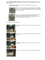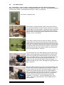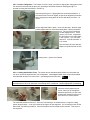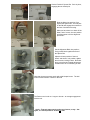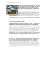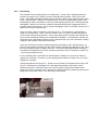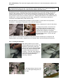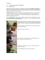
1
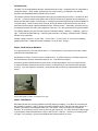
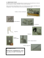
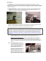
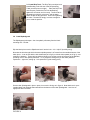
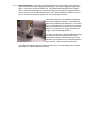
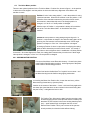
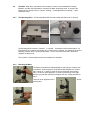
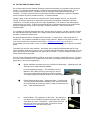
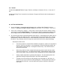
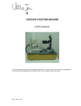
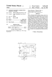
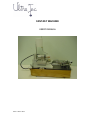
FANTASY MACHINE
USER’S MANUAL
2648.7 / 2648.2 Rev4
TABLE OF CONTENTS
INTRODUCTION
1.0 UNPACKAGING THE UNIT
2.0 AN OVERVIEW
3.0 SETTING UP
3.1 The Machine, 3.2 Install Dial Indicators 3.3 Install Drip Tank
3.4 Install Splashguard, 3. 5 Install Lamp
4.0 OPERATION
4.1 The Control Panel
4.1.1 Control of Tool-drive Motor
4.1.2
4.2
4.2.1
4.3
Control of Reciprocation Motor
Tool-drive Motor position
Moving Tool-drive Motor position
The Mast
4.3.1
The Mounting Block
4.3.2
Mounting the Mast.
4.3.2.1 Affixing the Rigidizer to the Mast
4.4
Drive Motor Setups
4.4.1
Position 1 - the “Home” position. Aligning the Mast to the unit’s working mechanisms
4.4.2
Position 2 Alignment
4.5
Horizontal Positioning – X, Y, θ
4.5.1
X Positioning.
4.5.2
Y Positioning.
4.5.3
θ Positioning
5.0 TOOLS
5.1
Mounting Tools into the Tool-drive Motor
5.1.1
Cylindrical tools
5.1.2
Slitting Tools
5.2
CUTTING AND POLISHING TOOLS
6.0
CUTTING INFORMATION
Appendix
INTRODUCTION
The Ultra Tec Faceting Machine has been manufactured since 1966. It displays Ultra Tec’s approach to
equipment design -- direct, simple, thorough and non-compromising – providing the user with the
precision and repeatability that fine lapidary work requires.
The Fantasy machine has been developed at the urging of professional gem cutters. It is based on their
“wish list” – a list that included mechanisms and controls for almost every possible axis of positioning. It
started out with that complex, but limited goal – making those advanced positioning controls available for
“concave cutting”. When we were done, however, we found that the equipment could not only do the
enhanced concave cutting originally intended but also “Fantasy stones” – essentially, geometric carving -something that allows free rein to the imagination of the user. So—the project became a goal exceeded.
The Fantasy Machine has gone through a period of extensive testing – tweaking – modifying – getting it
right. That period included learning – a learning that continues – but clearly, it was time for the Fantasy
machine to be introduced.
Fantasy cutting is complex. It’s not “easy” – it’s not “fast” – it’s not for kids. It is for lovers of lapidary,
perhaps better said – imaginative lovers of lapidary—it’s an art form. Enjoy it.
ABOUT YOUR FANTASY MACHINE
It is a precision device, but not a delicate device. For maintenance, it only needs normal “wipe-it-down”
cleanliness and reasonable care.
Pay attention to safety -- there are tools in multiple motion. In general, these are not sharp cutting tools,
but sometimes are, and are necessarily exposed. So -- treat them with respect.
As with any electro-mechanical device, there can be occasional problems--and if you experience one,
re-read the Owner's manual for the function involved, to assure that you are performing the operation
correctly. If you still experience a problem, communicate with your Ultra Tec representative or with the
factory.
Shown with a Mast mounted – how it will look “in use”.
ABOUT THIS MANUAL
Most Manuals start out by saying “Read this carefully before proceeding”. Our advice is to do what you
will probably do anyhow -- that is, “Browse through this Manual quickly, and then start trying things out –
go back to the Manual if something puzzles you”. Our reason: This is a complex, but very logical
machine. As a faceter you’ll figure it out most of it by just looking at it. For many functions it takes longer
to go through a verbal description than it does to just look at it—and try it. Obviousy, if something feels
“too tight”, or is “jamming”, go back to the Manual and read the section you need.
1.0 UNPACKAGING THE UNIT
The machine comes in protective packaging which you may want to save, along with its box, in the event
that future shipment or storage is necessary. These are the included items:
Please note that the Fantasy Machine is heavy, so you may want someone to help you with lifting it out of
its shipping box. Have a sturdy surface to set it onto, and a cleared place to put it.
The Base - the basic machine itself
Two Dial Indicators
Two Rigidizers
Drip Tank
Splashguard
Position 1
Alignment Block
Position 2 Alignment Block
Position 2 Spacer Bar
And, Tool Box that includes:
Cylindrical Tools: Copper/Maple/Phenolic –– diams.
8 mm, 13 mm, 17 mm; Slitting Tools Copper/Phenolic
– 60º, Slitting Tool Adapter; Tool Bushings. 3/32,
1/8, ¼;
2.0 An OVERVIEW
The Fantasy Machine provides multiple axis repeatable positioning for use of cylindrical tools (“mandrels”)
and Slitting tools (disc “grooving” tools).
These are the positioning features:
●
Initial Alignment – the faceting Mast is set onto the Fantasy Machine and easily aligned to a
“home positions” – an initial easily retrievable 0 reference.
●
X (in-out) directional positioning (“parallel stepping”) of the grinding/polishing tool, relative to the
workpiece is provided - Dial indicator readout.
●
Y (side-to-side) directional positioning (“parallel stepping”) of the grinding/polishing tool, relative to
the workpiece is provided - Dial indicator readout.
●
θ (theta – angular) 180º of angular positioning, of the grinding/polishing tool relative to the
workpiece is provided. The Pivot axis is the 0-0 position
●
Tweaker (“cheating”) -- radial micro-adjusting is provided
●
There are two settable motor positions – Position 1, in line with a cylindrical tool axis - that axis
intersecting the “pivot axis” (the axis of horizontal angular positioning) - and maintaining in-line
reciprocation regardless of θ angular setting. Position 2 is at 90º, for use of grooving type of tool it allows for setting the slitting tool so that it intersects the “pivot axis”, and it also maintains in-line
reciprocation regardless of θ angular setting.
●
Reciprocation amplitude is adjustable – from very little (including none) to over an inch and
reciprocation rate is adjustable up to 140 CPM – a high reciprocation rate is valuable for
polishing. The Reciprocation Motor is independent of other controls.
3.0 SETTING UP
3.1 The Machine – The machine should be placed on a workbench or desk surface. It is fairly
heavy—about 65 pounds—so be sure the workbench is sturdy and you may need assistance in lifting it
to the surface. The machine will need a plug-in electrical supply and a container for draining – a gallon
container is adequate.
3.2 install Dial Indicators – There are two Dial Indicators (these are shipped unassembled to avoid
damage). As you face the machine, the position at the close left corner is designated “X”; the
position at the right side, toward the back, is designated “Y”.
The two Indicators are identical. Insert each one into its bracket-- as shown in the photos, leaving a
small gap – several millimeters-- between the round dial case and the bracket.
Each of these indicators has an Indicator Anvil to set the indicator reading.
Note: The Indicator has an outer dial that the long needle tracks around – one full rotation being 1
mm (capable of very small incremental settings). There is a small inner dial that counts rotations of
the outer dial – it reads 10 turns, and then 10 more –so you can read 20 mm in all (.800”) [you can
squeeze another millimeter at the end of the scale]. When the following paragraph says: set the
indicator to 0-0 it means set the Dial Indicator’s long needle readout to 0 with the inner dial (rotation
counter) at 0.
3.2.1
The X Indicator Anvil (left) can be positioned by loosening the black knob at the left side of
the plate—sliding the anvil to the desired position, and then retightening the knob.
In setting up, set the X Indicator to 0-0 – there is some preloading, even at 0-0 (see the
boxed note, above). After initial mounting of the X Indicator, slide the Anvil against the
indicator shaft to get that reading (you just have to get the 0 setting close, because you can
“fine-tune” the alignment by turning the outer ring of the indicator until the outer 0 position is
exact).
3.2.2
The Y Indicator Anvil (right) can be
positioned by loosening the black knob at
the rear of the Mast Mounting Block -sliding the anvil to the desired position,
and then retightening the knob.
At the time of initial setup, this Anvil is
pulled away from the Dial Indicator – not
activated--at least until the Y linear
position of the Mast has been set. Later,
when the Y setting is involved in the
process, slide the Anvil into contact with the Indicator shaft—set it at 0-0.
3.3 Install Drip Tank - The Drip Tank post slips into a
black Bushing in the left rear of the Reciprocating
Table (see the picture on right). . Place the Drip Tank
onto the post, position the Post into the Bushing,
tighten the set screw, and it is ready. The flow rate is
adjusted by turning the valve stem, and the water
shuts off with an easy pressure. Avoid over tightening
the valve. The tank fits snugly, but loose enough for
you to rotate its position.
3.4 Install Splashguard
The Splashguard pulls apart – the clear plastic pulls away from the black
mounting disc. Do that.
Slip the black piece over the Spindle and set it into the hole – it’s a “slip fit” (but fairly snug).
Note that the hole through which the motor spindle passes is off center from the outside diameter of the
black piece – it can be set with the hole downward (as in fig.2) or with the hole upward (as in fig 3), or at
positions in-between. Those various positions allow you to set the amount of exposure of the Mandrel,
providing more or less splash protection – it’s a “judgment” setting that you will make (based on
experience – right now, setting up – hole upward is a good starting point).
FIGURE 1
FIGURE 2
FIGURE 3
Set the clear Splashguard in place—press it on over the O-ring as in figure 4. Note that there is a preinstalled drain and draintube that extends from the bottom of the clear Splashguard – lead it to an
appropriate drain container.
FIGURE 4
3.5 Install Lamp
The lamp mounts onto the pre-assembled stud located in the right rear corner of the Baseplate. The lamp
mounting lock has a snap-on design. Pull back the nylon ring, place the lamp onto the stud, and push
down the ring. You will feel the ring snap into the down position, where it holds the lap securely.
4.0 OPERATION
4.1 The Control Panel
The electronic control converts AC current to DC, which the motors require. It contains controls for both
motors that are part of the unit, the Tool-drive Motor and the Reciprocation Motor. Note that the motor
controls are independent – modifying the running characteristics of one of the motors does not affect the
other one.
4.1.1 Control of Tool-drive Motor The right-side Switch is a two-way ONOFF toggle for the Tool-drive Motor. It has a choice for motor direction – UP
for clockwise (CW) rotation of the tool, and DOWN for counter clockwise
(CCW) rotation of the tool. The central position of the switch is OFF.
The central knob is a speed selector for the Tool-drive Motor – most frequently,
the tool drive motor is operated at full or close-to full speed.
4.1.2
4.1.2.1
Control of Reciprocation Motor The left Knob combines both power and rate control for the
Reciprocation Motor. The extreme CCW position of the Knob is power OFF. Rotation starts and
increases rate as the Knob is rotated CW.
Setting the Amplitude of the Reciprocation Motor The amplitude – the in-line stroke – of
the Reciprocation Motor is variably adjustable, from the maximum stroke of 30 mm – over an
inch – to a minimal stroke approaching 0. Commonly, a full stroke is used (and the unit is
shipped that way), but often, because of the length of the particular tool that is being used,
less than full stroke is appropriate.
The setting is performed by engaging a screw that is visible in
the side “window”, as shown. The adjusting screw rotates with
the rotation of the motor – and to perform the adjustment,
obviously, the head of the screw must be visible (and so,
reachable) in the window. A slow jogging of the motor can bring
the head into view, or…
…it can be positioned by pushing or pulling the Tool-drive Motor Plate
(it’s OK to grip the Motor housing to do this as shown). This method will
not work if the head is located, by chance, in a straight line with the
reciprocation action (at an extreme of the reciprocation). If that
happens, jog the motor so that the reciprocation stroke moves to an
(approximate) half-way point, and try again.
In making the adjustment, CW rotation decreases the amplitude. CCW rotation increases the amplitude.
The Reciprocation motor is independent from the Tool Drive Motor—and none of these adjustments have
an effect on the tool drive, and, the Reciprocation motor can be left in a power OFF condition, that is, with
0 reciprocation.
4.1.2.2 Reciprocation Brake. If you want to use the machine with the reciprocation action turned off with the reciprocation platform stopped and held steady - you need to engage the Reciprocation
Brake. If you wish to do that, BE SURE THAT THE RECIPROCATION MOTOR IS TURNED
OFF to avoid possible damage to the motor which might occur if the Brake is applied while the
motor is trying to run for some extended period of time. Before the Brake is applied you will see
there is an amount of looseness, perhaps 1/8” in the reciprocation direction.
Use an Allen Wrench to turn the Brake-engaging set
screw CW (a tightening direction) - in the picture this
set screw is indicated by the white arrow. This should
not be a firm tightening - the end of this set screw has
been made smooth so as not to bite into reciprocation
platform - its purpose is to just stop movement (it’s a
“finger” on the reciprocating platform).
To return to reciprocation, release the Brake by turning
the setscrew CCW (a loosening direction) before
turning the Reciprocation Motor ON (as you turn the
setscrew, you will feel when the reciprocation platform
becomes free - ready to be driven by the motor.
You might notice that this feature is missing on other views - it is a later-added feature, which is
easily added to a machine that does not have it.
4.2
Tool-drive Motor position.
There are two optional positions for the Tool-drive Motor. Position One, shown in figure 1, is the position
in which the unit is shipped—and the position in which the initial setup alignment of the Mast to the
machine is made.
Position 1 is the “main setup position” – and is the position for using
cylindrical mandrels. When the Drive Motor is set into position 1, the
centerline of the mandrel intersects the pivot axis of the θ motion,
and remains in that relationship even if the θ angle position is
changed, or, if the X or Y linear position is changed. .
With the motor in Position 1, reciprocation is always in line with the
axis of the Tool-drive Motor shaft – in line with the axis of the
mandrel.
Position 2 is the position for using slitting and grooving tools. In
Position 2, reciprocation is always in line with the cutting plane of the
grooving tool, and remains in that relationship even if the θ angle
position is changed, or if the X or Y linear position is changed. .
In setting up Position 2, there is a procedure for aligning the cutting
plane so that it intersects pivot axis of the θ motion. It is usually a
good idea to do this alignment since it establishes a 0 Home position
for that tool. Once that alignment is made, the cutting plane intersects the pivot axis even if the θ angle
index position is changed, or if the X or Y linear position is changed.
4.2.1 MOVING MOTOR POSITION.
This view of the Motor mount Plate tells the story. Central in the photo
is the Position One Mounting provision. At the upper part of the photo
is the Position Two Mounting provision
Position One has the familiar Ultra Tec “keyhole” mount cutout – and
the Motor housing has the familiar cam gripping mechanism.
In removing the Motor from Position One, loosen the cam lever, pull the
Motor housing forward and up (see the photo).
Insertion is the reverse of that action – insert – side back firmly against the
two dowel pins (note that there are two notches in the motor housing that
the pins fit into) – and tighten the lever to lock.
For Position Two, slide onto the plate from the rear edge, push
forward engaging the two dowel pins that set the location (note
that there are two notches in the motor housing that the pins fit
into) -– push forward firmly--and tighten the lever to lock.
Removal from Position Two is just a reverse of the process.
In both positions, the electrical cable will track along.
4.3
The Mast. Most often, preparation of the workpiece is done on the standard flat Faceting
Machine, and after the preparation is complete, the Mast, holding the stone, is moved to the
Fantasy unit for further work.(in “concave” faceting – as distinguished from “fantasy” – that’s
always the case)
4.3.1
The Mounting Block. The Mounting Block will hold and position the Mast in the Y direction.
The Mounting Block includes a “tweaker” – a “cheater”. It operates in the horizontal plane – for
fine alignment of a polishing tool relative to a concave facet, if needed. It is analogous to the fineadjusting “cheater” device on the faceting Mast. To use, loosen the black knob, set the dial,
retighten the black knob.
The “keyhole” cutout accepts the cam-lock mechanism of the Mast
4.3.2
Mounting the Mast.
The Mast is mounted on the Mounting Block, fitting into the “keyhole slot”
in the Block. When doing that, verify that the Mounting Block’s “cheater
dial” is set at 0 – in order to retain an easy-to-remember home-setting
point. Perform a visual alignment—just sort of point things in the right
direction (no precision required) and tighten the cam, locking the Mast in
place.
There will be an alignment of the
position later.
“Home”
4.3.2.1 Affixing the Rigidizer to the Mast. It is necessary to eliminate lateral swinging of the Yoke. To
do this, a “Rigidizer” is provided – it mounts onto the Mast. Here are the mounting steps – it takes less
than a minute to do.
Note that two Rigidizers have been provided, the “RC”(Rigidizer for Concave) and the
“RF”.(Rigidizer for Fantasy).
The RC is for use in Concave cutting. It allows easy inspection of the added
concave facet – A truncated fron arm allows the raised Quill to swing toward
the user. While the work is being performed, the Yoke is pressed against the
rear arm of the Rigidizer.
The RF, for use in Fantasy cutting, completely eliminates Yoke swing and is
suitable for fantasy cutting, where inspections are less frequent and
positioning for easy inspection can be done by rotating the Quill, and then, reindexing the Quill position to continue work
Both Rigidizers mount in the same way.
Approach from under the Riser Block. The U cutout clears the Leadscrew.
Push up.
Push it all the way up – and push forward—firmly – against the rear face of
the Yoke.
Hold it firmly – tighten the set screws. Feel the Yoke – confirm that it is
rigidly held.
The RC – same process – of course, only the rear arm engages the yoke
4.4
Drive Motor Setups.
4.4.1 The Position 1 “Home” position. Aligning the Mast to the unit’s working mechanisms.
Alignment of the Mast to the Drive Motor is quickly and easily done. Alignment – and repeated alignment,
if that becomes needed – usually takes about a minute. Here it is, step by step:
The Position 1 Alignment Plate
Set the Position 1 Alignment Plate in place—there are two flats on
the motor Spindle that line up with the cutout in the Plate – set those
flats manually into a vertical position. Resting the bottom edge of the
Alignment Plate against the Motor mounting plate surface push the
Alignment Plate over the flats and flush against the face of the Motor
Housing – let go -- it will sit there.
Figure 1
On the Mast, set the Quill angle at about 90+ degrees. Raise the
height position of the Quill so that as the Mast is advanced forward
(which is what will happen next) the Quill will pass over the top edge
of the Plate. Using the X adjustment knob, advance the Mast toward
the Alignment Plate until the front end of the Quill is a small amount
higher than the top edge, and perhaps a quarter inch past the back
face of the Alignment Block - as shown.
Loosen the Base lock on the Mast (slightly) so that the Mast can be
rotated on the Mounting plate, and rotate the Mast so that the Quill
(still over the top edge of the Alignment Plate) is to the side of the
notch—by perhaps a half inch. Now, lower the Quill position so that
it comes to a rest on the top edge of the Alignment Plate, and
continue to lower until the angle readout is about 94 degrees – no
precision needed (my 94.6 is OK). Disengage the Angle Stop on the
Mast – back it off.
Now, as the Quill rests on the top edge of the Alignment Plate—and
the Base lock of the Mast is slightly loose, holding down the Base of
the Mast, against the top surface of the Mounting Block, rotate it – in
a direction to drag the Quill along the top of the Plate toward the
notch. At some point, the Quill “pops” into the notch – that’s it (you
can adjust the angle to 90º--but you don’t have to—it just gives a
“feeling” of having completed the task that has already been
completed). It is on center – relock the Mast Base lock. That’s
“home”. Using the X positioning Knob, move the Mast back to a
working position
That took many words to say – it is much quicker to do than to read.
4.4.2 Position 2 Alignment. The Position 2 “Home” setup is a matter of aligning the cutting plane of the
tool so that it intersects with the pivot axis, providing a retrievable dimension starting point (¶ 4.2.1
showed mounting the Drive Motor in Position 2).
Insert the grooving tool. Lightly tighten the set screw that holds it - it
will need to slide in and out slightly, as part of the alignment procedure,
that is, aligning the cutting plane of the tool with the θ pivot axis - “on
center”.
Set the Alignment Plate in place - down onto the plate - the back edge
pushed against the face of the Drive Motor Block. Slide it toward the
tool. The V groove in the brass
rod will engage the tool. That V
groove is on center - manipulate
the tool holder in-out until it aligns
in the V groove -- you can see it
and feel it. Lock the tool there - it
is on center.
This technique will work with ballshaped or cylindrical tools as well.
Looking down - groove tool centered
4.4.2.1 Setting Small-shank Tools. The section above described setting Position 2 Home when the
tool to be used is the standard Ultra Tec configuration. What happens when some commonly-available
small diameter shank tool is to be used? - (something that looks like this)
?
Section 5.0, further down, describes mounting tools, in general - but before getting into alignment of
small-shank tool, here’s an instruction on mounting them, in particular. Use the appropriate Tool Bushing
Insert and loosely tighten the set
screw - when you go through the
alignment procedure, you will need
to adjust the extension of the tool to
set it into the on-center position
The extended extension of the tool - since the Tool Bushing is an added element - brings the cutting
portion beyond center -- it can’t be backed off enough to do the alignment. It is necessary to back off the
Motor itself, and that is provided for. Remove the Motor and set it aside for the moment. Then, here is
the sequence:
Get the Position 2 Spacer Bar. Set it in place,
engaging the two dowel pins.
Slide the Motor into position, firmy
against the Spacer Bar - the rear pins
on the Bar will engage the notches on
the face of the Motor Housing.
What you have done is to back off the
Motor, and of course, the tool position
providing space to do the alignment
procedure.
Set the Alignment Block into position firmly pushed back against the face of
the Spacer Bar.
Adjust the linear position of the tool
shank, and when it is in position, tighten
the set screw, locking it there. Note that
there is an amount of lateral adjustment
available from the Tool Bushing as well.
Note that the same process works with a ball shaped cutter. The ball
makes contact with the V sides on the Rod
The Rod moves in and out - longer or shorter - to manage engagement
with the tool.
Again - That took many words, and many pictures, to say – but
again, it is much quicker to do than to read
4.5 Horizontal Work Positioning – X, Y, θ
4.5.1 X Positioning.
When you want to adjust the position of the workpiece relative to the
tool in an X direction, you turn the nearby Knob [C] – CW rotation of
the knob brings the tool closer to the front edge, CCW rotation
moves it away from the front edge. What you are actually doing is
adjusting the position of the X Traveling Plate which carries the Tool
Drive Motor. The X position is reflected on the X Dial Indicator.
At start out – when the Indicator was mounted -- it was set to a
readout of 0-0. If for some reason it is no longer 0-0 (well, you may
have been fiddling with the machine—that’s fine), reset it there.
(Notice, by the way, that at this Home-0 setting, the close edge of the
X Traveling Plate is pretty well aligned with the close edge of the Baseplate – that may become
handy information later on).
The Traveling Plate has a range of +/- 25 mm (1”) from the Home-0 position – so, features as far
apart as 50 mm (2”) can be put onto the workpiece.
The range of the Dial Indicator is 20 mm (.8”) so, from its initial setup position (“Home 0”), an X
offset up to 20 m can be done. That allows for features with up to 40 mm (1.6”) of separation on
the stone without resetting the indicator position.
For X offsets larger than 20 mm, resetting of the Dial Indicator is needed. To do that—at the end
of the 20 mm stroke, with the Indicator reading 0 and the inner rotation counter at 20 (0-20),
loosen the knob that holds the Anvil in position and reset the Anvil so that the Indicator again
reads 0-0 – lock the Anvil. It is now ready for the setting of new additional offset positions. You
can get back to the Home-0 by running the process backwards. An example: suppose you have
performed the resetting and continued working on your stone, and you’ve put in your last feature
with the Indicator reading, lets say, 4.5 mm (that is, the inner dial now reads 4, and the main dial
now reads ..5) – and, you’d like to reset to the Home-0 position. Turning the C Knob, return to
the 0 – 0 Indicator reading, unlock the Anvil and reposition the Anvil so that the indiator reads 020; again turning the C Knob, return to the 0-0. That’s it, you are back to Home-0.
All of this allows you to return to any particular offset feature position – for modification, polishing,
whatever, if you kept track of the Indicator reading where you placed that particular feature.
4.5.1.1 If you get “lost” and need to reestablish the X Home-0?
Remember? You took note that when you did the original alignment of the Mast to the tool--the
close edge of the X Traveling Plate was aligned with the close edge of the Baseplate. If you get
“lost” (perhaps after going through a number of resettings of the X position – and just losing
track), it is helpful to know that edge-to-edge relationship exists – a sort of “macro” target.
You can precisely reset the X home 0 position with this procedure: Using C, move away from
that edge-to-edge condition by perhaps a half inch, and, referring to Section 4.4, above, set the
Alignment Plate in position, set the Quill of the Mast onto the top edge of the Alignment plate (as
in 4.4, figure 4 – but keeping the Mast firmly locked to the Mounting Block), drag the Quill along
the top of the Plate toward the notch by rotating C. When the Quill “pops” firmly into the notch –
that’s it. Reset the X Home-0.
4.5.2 Y Positioning.
This is similar to the preceding section on X positioning – except, that in making adjustments,
instead of moving the tool’s position, you are moving the Mast’s position. When you turn the
Knob – CW rotation withdraws the Mast from the Tool Drive Motor, CCW rotation moves it closer
to the Tool Drive Motor. What you are actually doing, of course, is adjusting the position of the
Mounting Block which carries Mast. At the end of the alignment process, the Y Indicator was left
disengaged—and there are common conditions (described below) where engagement of the Y
Indicator remains unnecessary – and so remains disengaged. When it is needed, however, the Y
position is set on the Y Dial Indicator .
There is no strict “Home-0” position for Y as there is for X. This is because Y positioning is a
matter of user judgement – until a Y feature is added. Once a Y feature is added, that position
can be used as a positioning reference – that is, when that position is selected, the indicator can
be set so that subsequent positions are measured and resettable. (An observation: Usually, the
workpiece stone is significantly narrower in the Y dimension than it is in the X dimension, making
resetting of the indicator a less likely requirement).
At the start of the process (after completing alignment of the Mast to the Tool Drive Motor), set
the first working angle on the Mast, set the working height of the Mast (the Z direction) and, using
the knob, position the stone in relation to the tool. Turn on the Reciprocation Motor so that you
can observe the amplitude of the Tool’s movement, and set the stone’s Y position in relation to it
– (a non-critical judgement call).
If you are working with a cylindrical tool, with the Motor in Position One, there is no reason to
engage the Y Indicator. If, however, you are working with the Motor in Position Two, you would
engage the Y Indicator.
The Mounting Block has a range of 3”. Similar to the X situation, the Indicator has a range of 20
mm (8”). Read the part of paragraph 4.5.1 that deals with resetting of the Indictor, if that
becomes necessary—it works the same way as the X position (except that a specific Home
position, as X has, is replaced in the Y direction by a selected reference position (see the second
paragraph of this section, above, for a description of this setting)
4.5.3 θ Positioning This controls the angular position of the tool, in the horizontal plane, relative to the
workpiece.
Just as X, Y and Z are used to describe linear directions of positioning. θ, the Greek letter “theta” is used
for radial positioning around an axis. We could have called it “indexing”, as it is called on the faceting
Mast, but here, the designation of θ avoids confusion between those two devices.
θ positioning is on the Y traveling Plate, and the entire plate moves to any new θ setting. The axis of θ
rotation is the centerline of the Pivot Knob which intersects the centerlines of the Tool drive Motor in
Position One and Position Two – and so, this axis is directly associated with the Home-0 alignment – as
the θ position is moved, the tool remains on the θ axis – allowing radial features to be centered around a
settable point. θ can be set through a full 180º range - settings in 5º increments are standard (1º
increments are available with the HD Protractor mod).
Note that when the Y traveling Plate is rotated to a new θ position, it carries with it the reciprocation
mechanism – continuing the reciprocation in line with the cutting action.
At time of alignment, θ is set at 0º (left photo).
To change the θ position, loosen the Pivot
Knob, push in the lever, as shown - that
swings out the detent pin, and swivel the Y
traveling Plate to align the new angular
position (to move the Plate, grip the housing of
the reciprocating motor) - move to the new
angular position.
(NOTE: with the 1º HD Protractor installed, see the pictures below, the detent pin is locked out and
angular position is set visually, using the line on the indicator block, and locked with the Pivot Knob)
4.5.3.1 Locking the θ Position
When the θ position is set, it can be
locked by tightening the Pivot Knob. The
standard 5º notches will usually have
sufficient locking force without tightening
the knob, but, if the HD Protractor Mod
is installed, tightening of the Knob is
necessary. In general, finger tightening
is sufficient, but, the knob does have a
side hole for added tightening or
loosening, if desired.
A CW angle setting is shown on the
left, a CCW angle setting shown on
the right
5.0 TOOLS
5.1
Mounting Tools into the Tool-drive Motor
5.1.1– Cylindrical tools
Cylindrical tools (commonly referred to as “mandrels”) are used when the Drive Motor is in Position
One. In that position the reciprocation action is always in line with the axis of the tool. Regardless of the
θ position, the reciprocation action remains in line with the axis of the tool and the tool’s rotational axis is
aligned to the rotational axis of the θ settings.
The Basic Adapter is attached to the Motor Shaft, and shipped with the machine – it is not intended for
removal. It has a hole of .625” (5/8”). .625” is a standard shank diameter for some available large
diameter tools, and if one of those tools is used, the tool inserts directly into the Basic Adapter, and is
held there by tightening the set screw.
5.1.1.1 Tool Bushings For the many other available tools, with their various shank diameters, a set of
Tool Bushings is provided, with diameters of 3/8,1/4, 1/8 and 3/32”. These Tool Bushings have outside
diameters of .625 and fit into the Basic Adapter.
This picture shows inserting an Tool Bushing into the .625 diameter hole
of the Basic Adapter (as you can see, the Tool Bushing selected for this
photo has a 1/4” hole – selected to accept the particular tool planned for
use).
Push it Tool Bushing in – Align the flat on the Tool Bushing with the set
screw in the Basic Adapter
Tighten the set screw to hold it there.
You see that near the leading edge of the Tool Bushing there’s a set
screw – available to hold the cylindrical tool…
The cylindrical tool is inserted – and, in turn, locked in place with the
setscrew in the Adapter.
Mount the Splashguard, and you are ready to proceed.
5.1.2
Slitting Tools.
Slitting tools are used when the Drive Motor is in Position Two In that position the reciprocation action
is always in line with the peripheral edge of the tool. The reciprocation action remains in line with the
peripheral edge of the tool regardless of the θ position,
The two Angular Tools that Ultra Tec supplies with the kit, one a 45º included angle and the other 60º.
These mount onto a special Adapter Shaft:
The Slitting tools…
A slitting tool is selected…
Ready the Adapter Shaft and screw, and the wrench. Remove
the screw and set it to the side for a moment…
Mount the tool to the Adapter Shaft – carefully and patiently – it’s
a close fit, to maintain good concentricity. Engage the screw and
tighten it snugly.
It’s ready for mounting to the Tool Drive Motor. Insert the
Adapter into the Basic Adapter; tighten the set screw
The slitting tool is positioned over and in line with the axis of θ
rotation (not always critical, but sometimes desirable)…
5.1.2.1 Purchased Slitting Tools
For “off the shelf” slitting tools that come with attached shanks, ¼“, 1/8”, or 3/32”, use the following
procedure:
A) After moving the Motor to Position Two, insert the Tool Adapter (the same as used for the
cylindrical tools) with a diameter appropriate for the tool you will be using – lock it.
B) Inset the tool. You will have some leeway in setting the linear position of the cutting tool. Lock it
in position with the set screw.
5.2 CUTTING AND POLISHING TOOLS
We’ve learned that Concave faceting IS strongly related to flat faceting, and is properly called Concave
faceting. A comparatively small number of cylindrical tools (mandrels) accomplish the task. Yes, of
course, it can get pretty “fancy”, and there is room for creativity, but still, within faceting design
“discipline”. A look for concave tools on Internet sites reveals the availability of a number of diameter
sizes (sometimes in inches, sometimes metric) – in several materials.
Fantasy cutting, on the other hand is a craft much more closely related to carving. It is Geometric
Carving, in which the symmetry (or purposeful non-symmetry) is craftsman controlled—craftsman
“dreamed up”. In Fantasy cutting, tools are a major consideration. The number of tools that might be
useful becomes very many. A visit to the workshop of such a craftsman typically reveals a wall of tools
with sizes ranging from very small to very large, of different materials – much of it the result of
experimentation.
It is a situation in which the selections are many, and the choice is growing. It is also a situation in which
we understand that many purchasers of a Fantasy machine have already ventured into this sort of work
and have a collection of favorite tools.
Our plan has become that we will supply certain materials – in certain sizes – and include them in a
“starters kit”. The “standard” materials are copper, maple, phenolic. Right now, the sizes are limited – but
if you need a certain size, contact us (email is best – [email protected]), we will try to
accommodate your need. (and if it is not a completely “oddball” size, we may add it to the list of available
sizes).
Technically, we can offer other materials – specifically, we’ve made and experimented with Zinc and
Corian mandrels. Right now, there’s no “plan” to proceed with standard tools in those materials, but if you
have a strong wish to have a particular tool, again, talk to us about it – we have a desire to support your
efforts in this relatively new field.
All in all – faced with the impossibility of offering, and having in inventory of hundreds of tools – it is better
for us NOT to be a middle man. It is better for you, the user, to purchase directly from the tool suppliers –
google them. Here’s a few suggestions—
●
Special materials—that have been very successful in flat faceting – “Lightning Laps” and
“Batt Laps” have made mandrels available.
From the Lightning Lap page – “ The advantage of the LLMandrel is in the ability to have just one lap to do all your
work, just by cleaning and changing the polishing medium.
Your angle-integrity is preserved, as there are no lap changes” (www.lightninglap.com).
●
LASCO offers and large array – shapes and sizes - of carving tools.
The finest diamond mesh that is available is 600, but we found that
we could take that to a polish (on quartz)—using a hard felt bob (see
next). www.lascodiamond.com.
●
Hard Felt Bobs. The emphasis is on the “hard” – the right type to
use (there’s an rock-hard [too hard] and a soft [too soft] – double
check when you order. Inexpensive – a little runout won’t hurt – at
this point, the stone has been formed - let it bounce around.
www.feltbobs.com Use them with a slurry.
5.2.1 THE KIT:
Included are Cylindrical Tools of Copper, Phenolic, and Maple, in diameters of 8 mm, 13 mm, and 17
mm
Included are Slitting Tools of nominal 24 mm diameter of Copper and Phenolic with included angles of
60º and 45º.
6.0 CUTTING INFORMATION
●
A very useful book – an interesting and informative read - confirming that “Fantasy” is close to
carving – is Lapidary Carving for Creative Jewelry by Henry Hunt. It’s new at $25 – very worth it.
●
This is in the “coming soon” category – coming with in a few months (this written in March of 2010) –
is an instruction book by Dalan Hargrave. Very good news! Dalan is a extraordinary lapidary artist
who is happy to share his expert techniques – a clear writer as his published article have shown.
●
The various tools would be used with Diamond Powder slurries – coarse diamond for cutting, and, for
polishing, in addition to fine diamond (14K – commonly used by many professionals, 50K – used by
“perfectionists”), Aluminum Oxide slurry or Cerium Oxide slurry can be used. Various oils are used
as carriers – very commonly, olive oil (a carry-over [?] of the use of olive oil in diamond faceting).
Miscellaneous Minor notes:
●
There are inexpensive contact holders available in drugstores – plastic, two compartment
devices. These are very handy – one compartment is used for holding dry powder; the
other holds the diamond/oil mix. The hinged lid closes nicely. Use a black marker to
identify the mesh inside.
●
When using a ball end cutter, straight forward plunging leads to swirl marks (the dead
center isn’t moving much – it’s a dead center all right). Approaching the stone from the
side at some angle or other, provides the same cutting profile, but much swiping action.
●
Setting a rapid reciprocation is generally advantageous. The side swiping action acts
against the radial grooving that develops in the small contained areas.
●
Through much of the process you will probably not be using water or a thin slurry, at
which times you may not want to use the Splashguard. The clear plastic part is easy to
remove and set to the side. Leave the black part in place (it functions to protect the
motor area.
Appendix
A. HD Protractor Mod. (1901.85) This modifies the
theta positioning increments from the standard 5º to 1º.
The Kit includes the items shown.
It is a self-installable Kit - only a small screwdriver is
needed.