1
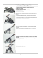
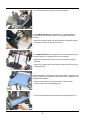
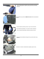
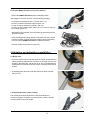
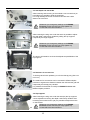
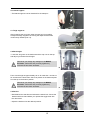
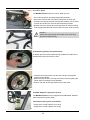
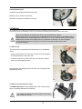
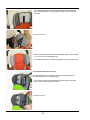
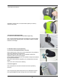
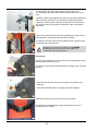
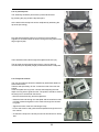
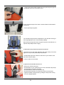
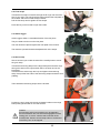
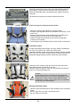
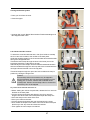
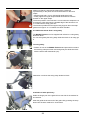
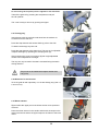
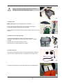
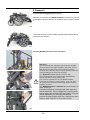
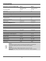
Bingo Evolution
Therapist and Carer manual
Medifab Medical Fabrication
Australia: 26 Pardoe Street, Devonport, TAS 7310 New Zealand: 7 Allens Road, Ashburton 7700
Call: 1300 543 343 (AU)
0800 543 343 (NZ)
www.medifab.com
[email protected]
ABN # 49 828 922 466
Please Read Before Use
User manual for BINGO Evolution
Contents
1
Page
Common Information __________________________________________________________________________ . 2
1.1
1.2
1.3
1.4
1.5
Preface_________________________________________________________________________________
Application ______________________________________________________________________________
Declaration of conformity ___________________________________________________________________
Terms of warranty ________________________________________________________________________
Servicing and repairs ______________________________________________________________________
2
2
2
2
2
2
Safety Instructions ____________________________________________________________________________ 3
2.1
Meaning of symbols _______________________________________________________________________ 3
2.2
Common safety instructions _______________________________________________________________3-5
3
Delivery and preparing for use ________________________________________________________________ 6-11
4
Adjusting and adaptation possibilities _________________________________________________________ 11-16
4.1
Wheel lock _____________________________________________________________________________ 11
4.2
Height adjustment of the push handle ________________________________________________________ 11
4.3
Seat depth and seat width _________________________________________________________________ 12
4.4
Retainer for accessories __________________________________________________________________ 12
4.5
Lateral supports _________________________________________________________________________ 12
4.6
Hip supports ____________________________________________________________________________ 13
4.7
Thigh supports _________________________________________________________________________13
4.8
Back height ____________________________________________________________________________ 13
4.9
Recline _______________________________________________________________________________ 13
4.10 Footrest hanger, angle adjustable ___________________________________________________________ 14
4.11 Footrest hanger, 90° _____________________________________________________________________ 14
4.12 Lower leg length ________________________________________________________________________ 14
4.13 Footrest _______________________________________________________________________________ 14
4.14 Footrest flip up lock ______________________________________________________________________ 15
4.15 Detaching & attaching the seat unit __________________________________________________________ 15
4.16 Seat unit in opposition to the driving direction __________________________________________________ 15
4.17 Tilt ____________________________________________________________________________________ 16
4.18 Detaching wheels with quick-release _________________________________________________________ 16
4.19 ASF - Adaptive suspension system___________________________________________________________ 16
4.20 Pneumatic tyres _________________________________________________________________________ 17
5
Zubehör __________________________________________________________________________________17-34
5.1
Swivel lock _____________________________________________________________________________ 17
5.2
Soft accessory bag ______________________________________________________________________ 17
5.3
Large accessory bag (in progress)___________________________________________________________ 19
5.4
Headrest pads__________________________________________________________________________ 20
5.5
Headrest pads (low version) _______________________________________________________________ 20
5.6
Headrest bracket „universal“ _______________________________________________________________ 21
5.7
Headrest with occiput upholstery ____________________________________________________________ 21
5.8
Thorax pads ____________________________________________________________________________ 21
5.9
Pelvic stirrup ___________________________________________________________________________ 22
5.10 4-point lap belt __________________________________________________________________________ 23
5.11 Five-point harness _______________________________________________________________________ 23
5.12 Foot straps _____________________________________________________________________________ 25
5.13 Ankle hugger ___________________________________________________________________________ 25
5.14 Groin strap _____________________________________________________________________________ 25
5.15 Fixation jacket __________________________________________________________________________ 26
5.16 Chest-shoulder harness ___________________________________________________________________ 27
5.17 Abduction block _________________________________________________________________________ 28
5.18 Grab rail with upholstery __________________________________________________________________ 28
5.19 Therapy tray ____________________________________________________________________________ 29
5.20 Retainer for accessories,grab rail or therapy tray _______________________________________________ 29
5.21 Winter warmer __________________________________________________________________________ 29
5.22 Sheep skin insert ________________________________________________________________________ 30
5.23 Rain cape ______________________________________________________________________________ 30
5.24 Canopy incl. adapter and rain cover _________________________________________________________ 30
5.25 Attendant brake _________________________________________________________________________ 31
5.26 Drum brake ____________________________________________________________________________ 32
5.27 Buggy-Board / Kiddy-board ________________________________________________________________ 32
5.28 Sun shade _____________________________________________________________________________ 33
5.29 Accessory and diaper bag _________________________________________________________________ 33
5.31 Headrest speakers, for headrest pads ________________________________________________________ 33
Transport ___________________________________________________________________________________ 34
6.1
In the Trunk of a car______________________________________________________________________ 34
6.2
Using BINGO Evolution rehab pushchair for bus transport ______________________________________ 34
Maintenance / Service and Repairs _____________________________________________________________ 35
6
7
8
Technical data _______________________________________________________________________________ 36
9
Your notes __________________________________________________________________________________ 37
1 Common Information
1.1 Preface
Thank you for selecting the BINGO Evolution wheelchair. We have designed this high-quality product to make
your life safer and easier, and we’ve included this manual to help you use and care for it. Please read the following
instructions to make sure you use this product as recommended. If you have any further questions, or if
you have any problems, please contact your healthcare provider.
We hope that BINGO Evolution meets your expectations.
The design, as described in these instructions for use, are subject to technical alterations without notice.
1.2 Application
Rehab pushchairs, paediatric postural positioning systems or strollers are appropriate for individuals
requiring mobility assistance.
Assistance may be required due to:
• Paralysis (paraplegia / tetraplegia or tetraparesis)
• Loss of limbs (dysmelia/lower limb amputation)
• Infantile/spastic cerebral palsy
• Spina Bifida
• Muscle and nerve disorders
• Imperfect osteogenesis
• Poliomyelitis
1.3 Declaration of Conformity
HOGGI® GmbH as manufacturer with sole responsibility declares that the BINGO Evolution conforms to the
requirements of the 93/42/EEC Guidelines.
1.4 Terms of Warranty
Warranty applies only when the product is used according to the specified conditions and for the intended
purposes, following all manufacturer’s recommendations.
The manufacturer is not responsible for damages caused by components and spare parts not approved by
the manufacturer.
1.5 Service and Repairs
Service and repairs on the BINGO Evolution should only be carried out by authorized HOGGI® dealers.
Should any problems arise, please contact the dealer who supplied your BINGO Evolution.
Authorized dealers only fit original HOGGI® spare parts.
For preparing, repair and service, the following tools are required:
Allen wrench,size: 3 mm, 4 mm, 5 mm and 6 mm
Screw wrench, size: 10 mm, 13 mm, 19 mm und 24 mm
Your authorized HOGGI® dealer:
2
2
Safety instructions
2.1
Meaning of symbols
Caution!
Warning of possible danger of accident and injury. Warning of possible technical damage.
Information!
About use of the product.
Information!
For service-personnel.
Attention!
Read manual before use!
2.2
Common safety instructions
Read manual completely before use!
Familiarize yourself with handling and functions of the product before use and practice the
various functions.
You are responsible for the safety of your child. The safety of your child could be
affected if you do not follow the instructions of this manual. Nevertheless not all possible
circumstances and unpredictable situations can be covered by this manual. Reason, care
and circumspection are not features of the product, they are required of persons, who use
the product. The person, who is using the product and its accessories should understand
all instructions and should explain them to every person using the product and its
accessories.
If instructions are not clear and further explanations become necessary, or if you have
further questions please contact your HOGGI® dealer.
Strap your child at all times, when they are in the wheelchair.
HOGGI® points out, that any use beside the typical use can be dangerous. The pushchair
is not suitable for jogging, running, skating or similar activities. Swivelling front wheels tend
to wobble at higher speed, which can cause a sudden stop and tip over of the pushchair.
Use the pushchair only at regular walking speed.
Under no circumstances leave the handle bar while pushing and never push the chair
away.
The pushchair should only be used on solid level ground.
Use your pushchair as intended by the manufacturer. For instance, do not drive into
obstacles (including steps, curbs) without braking.
To clear obstacles such as steps and curbs, tilt the pushchair onto the rear wheels (pull it
backwards to go up; to descend, slowly lower it forward).
Do not go up or down stairs without the assistance of another person. If devices such
as ramps or elevators are available, please use them. If they are not available, then the
pushchair should be carried over the obstacle by two persons.
Do not stand on the footplate when getting into or out of the rehab-buggy.
3
Pay particular attention when on slopes and inclines to prevent:
- the child from falling out of the pushchair
- the pushchair from tipping over
- the pushchair from rolling away
Only lift the pushchair by parts that are solidly attached:
- front frame tube above the front wheels
- front axle
- push handle
If you have to park on a slope, face the pushchair uphill with the brakes engaged and
ensure that the seat is in the upright position. There is a risk that the pushchair might tip
over backwards if the seat is the reclined position.
Before leaving the pushchair and before getting into and out of it, always lock the wheel
locks.
When your child reaches for objects in front, to the side or behind the pushchair, be sure
that he/she does not lean out of the pushchair too far since the shift in the center of gravity
might cause the pushchair to tilt or tip over.
The handling of the pushchair is strongly influenced by tyre pressure. Correctly inflate tyres
considerably improve its maneuverability. The air pressure should be at least 2 bar
(200 kPa resp. 29 PSI).
Please be aware that with certain footrest settings the footrest can collide with the caster
wheels.
Please keep packaging material away from children. Plastic packaging presents the
danger of suffocation.
Never leave your child unattended in the pushchair even when they are strapped in and
the brakes engaged.
In the dark, the user should wear light clothing or clothing with reflectors in order
to improvevisibility. Ensure that the reflectors if installed are easily visible. We also
recommend installing active illumination.
Before using the pushchair, both folding guards and the seat must be firmly locked in
place.
Static stability is at 10,5° inclination.
Attaching heavy bags or other weight to the push handles can adversely affect stability.
Caution!
Regard specially during adjusting the recline, the tilt in space function and the footrest
hanger angle the danger of getting caught for the child by protruding arms or legs into
flexible parts of the BINGO Evolution.
4
Caution!
All upholsteries are hardly inflammable and meet the claim EN 1021 part 1 (cigarette test)
and part 2 (match test). But that doesn`t protect the user in the seat unit to suffer burnings
by careless handling with blaze or open fire.
Disposal of waste: The packaging material as far as metal, aluminium and plastic parts can
be recycled. The recycling must be operated according to the national and legal terms.
The maximum weight that can be carried in the accessories bags is 3 kg (model “soft”) or
rather 8 kg (model “large”).
Trays must not be loaded with objects heavier than 5 kg.
The pushchair is only intended to carry one child at a time.
The maximum load for the BINGO Evolution is 60 kg.
The maximum load for the BINGO Evolution seat unit is 50 kg (body weight including
other load).
Accessories and add-ons reduce the maximum load proportionately.
Attention!
We recommend that, wherever and whenever possible users transfer to the seats installed
in the motor vehicle and use the corresponding vehicle restraint systems, because this is
the only way to ensure optimum protection of the passengers in case of an accident.
Your BINGO Evolution Rehab Pushchair was successfully tested in accordance with
ANSI/RESNA WC/19 and ISO 7176/19 (Crash Test).
It is, however, possible to use your BINGO Evolution Rehab Pushchair as a seat in a
motor vehicle, if our “Tie down Kit” (article 3231-7300) as well as appropriate restraint
systems are used.
Your BINGO Evolution is admitted for use as a seat in a motor vehicle yet.
This Rehab Pushchair is equipped with back angle and seat tilt adjustment. Turn the toggle
lever on the backrest and let engage the backrest in the first position. Using the seat tilt
adjustment you must bring the backrest into almost upright position (max. 20°). Observe
the specifications under 4.9 and 4.17 in this user manual.
Be careful in case of extreme temperatures. The wheelchair can heat up significantly when
in the sun or in the sauna. In extreme cold, there is a risk of hypothermia.
Caution!
Excess strap ends on accessories may be trapped in the tilt mechanism and can avoid the
engagement of the locking pins. In such a case the seat could fall off the mobility base.
Shorten excess strap ends on accessories so that they can not be trapped.
Check by pulling the seat sharply forward that the seat unit is properly engaged. Check
that the locking pins are completely engaged. Push in completely, if necessary.
The assembly of a seat shell is only permitted within the specified seating area.
The manufacturer of that new product combination has to test the stability and the adherence of the maximum load before commissioning.
Whenever you change any settings on the BINGO Evolution, make sure that you
firmly tighten any screws that have been loosened.
5
3 Delivery and Preparing for Use
The original package contains the following components:
• mobility base, folded
• seat unit and backrest folded
• seat-, backrest-, hip- and lateral upholstery
• instructions for use
• accessories as ordered
1
Please remove the transport safety items and packaging material
carefully.
To unfold the BINGO Evolution please proceed as follows:
• Use the black handle grip on the pushbar to lift the pushchair and
unfold it until you can set it on its wheels.
2
• Press the pushbar backwards until the folding guards engage
hearable.
• Check both folding guards and engage them if it`s necessary.
3
• Push the rear wheels on the rear axle stub until the quick release
engages.
• Ensure that the wheels are safely fixed on the axle stub by pulling
in the opposite direction.
4
• Pull the backrest and erect it.
5
6
• Turn the toggle lever on the backrest (6) and let engage the
backrest in the first position.
6
• Pull the seat unit on the backrest to the back (7) until the
mechanism of the tilt function engages hearable in the first
position.
7
The illustration (8) shows a BINGO Evolution with the backrest and
the tilt function engaged in the first position.
8
• After pulling the active handle the angle of the seat unit can be
adjusted (9).
9
Tilt in space function (10).
10
7
• Cut the transport safety (cable connector) carefully.
11
If your BINGO Evolution is equipped with an angle adjustable
footrest hanger the footrest could be in a hinged position for the
transport.
• Swing the footrest hanger with the footrest in the desired position
and clamp it firmly with the clamping lever.
12
If your BINGO Evolution is equipped with a footrest hanger 90° the
footrest could be in a hinged position for the transport.
• Swing the footrest below, pull the locking pin and let it engage
hearable.
• Check with a sharp push at the footrest hanger if the locking pin is
located securely.
13
Before mounting the upholstery it is recommended to adjust the seat
unit according to your requests as described under „4 Adjusting and
adaptation possibilities“.
• Place the seat cushion on the seat and fix it with the snap
fasteners below the front seat edge (14).
14
• Fix the snap fasteners below the backmost seat edge also (15).
15
8
The hip supports can be detached for the transport to achieve a
compact folding size.
• Plug the hip supports on the brackets as shown (16).
16
• Pull the hip support upholstery from the top onto the bracket, so
that the cushioned side points to the inner side and fix it with the
Velcro fasteners.
17
The illustration (18) shows the BINGO Evolution with a mounted hip
support including upholstery.
18
The thigh supports get mounted identically as the hip supports on
the seat plate.
• Pull the upholstery of the thigh supports as shown starting from the
front, so that the padded side shows to the inner side and fix it with
the Velcro fasteners.
19
The lateral supports can be detached for the transport to achieve a
small pack size.
• Plug the side supports on the backrest tubes as shown (20).
.
20
9
• Pull the lateral support upholstery onto the bracket, so that the
cushioned side points to the inner side and fix it with the Velcro
fasteners.
21
The illustration (22) shows a BINGO Evolution with inserted lateral
support.
22
• Pull the backrest upholstery with the cap onto the backrest.
• Fix the backrest upholstery on top with the Velcro fasteners.
• Insert the backrest upholstery between backrest and seat.
23
• Guide the Velcro fasteners through the long hole as shown (24)
and fix it.
24
Illustration 25 shows a fixed backrest upholstery (back view).
25
10
To fold the BINGO Evolution proceed as follows:
• Ensure the BINGO Evolution with the attendant brake.
We suggest to achieve the most compact folding package:
• to bring the seat angle into the 0° position (see 4.17)
• to fold or to detach the lateral supports (see 4.6)
• to drop off the hip supports (optional), (see 4.5 )
• to swing up the footrest hanger (see 4.10 or 4.11) and to swing up
the footrest (see 4.13).
26
• Stand behind the pushbar. Pull both folding guards and push the
pushbar forwards.
• After activating both folding guards encompass onto the pushbar.
Fold the pushbar forwards and keep holding it during the folding
process until the BINGO Evolution is folded on the floor.
• Fold the backrest as shown (27) (see 4.9).
27
4 Adjusting and adaptation possibilities
4.1 Wheel lock
• To put the wheel lock on push the wheel lock lever downwards and
roll the pushchair slightly back or forward, so that the lock pins can
engage in the brake disc. Never use force! This could damage the
quick release mechanisms and the wheels could fall off and cause
injuries.
28
• To disengage the wheel lock pull the wheel lock lever upwards
with your toe.
29
4.2 Height adjustment of the pushbar
The ratchet joints allow adjustment of the push handle to a
convenient height. To operate the ratchet joints, push the buttons
on the outside of the push handle.
30
11
4.3 Seat depth and seat width
After loosening and removing of the marked screw connections (on
both sides) it is possible to slide the seat plate.
For a high stability the screw connections should have a wide
distance to each other.
31
Whenever you change any settings on the BINGO
Evolution, make sure that you firmly tighten any
screws that have been loosened.
After loosening the wing nuts under the seat it is possible to adjust
the seat width continuously variable by sliding the hip supports
respectively the thigh supports.
32
Whenever you change any settings on the BINGO
Evolution, make sure that you firmly tighten any
screws that have been loosened.
The arrows in illustration 33 show the adjustment possibilities of the
hip supports.
33
4.4 Retainers for accessories
To fix the grab rail with upholstery or to fix the therapy tray (See 5.18
und 5.19.)
The retainers for accessories can be mounted in different depths
positions to organise the distance between the child and the grab rail
respectively the therapy tray variable.
34
It is possible for the dealer to modify the BINGO Evolution with
different depths positions.
4.5 Hip supports
After loosening the wing nuts under the seat (32) the hip supports
can be adjusted concerning the depth continuously variable. After
loosening the marked screws (35) it is possible to adjust them also
on the bracket.
35
Whenever you change any settings on the BINGO
Evolution, make sure that you firmly tighten any
screws that have been loosened.
12
4.6 Lateral support
• The lateral supports can be detached for the transport.
36
4.7 Thigh supports
After loosening the wing nuts under the seat (32) it is possible
to adjust the thigh supports concerning the depth and the width
continuously variable (see 4.3).
37
4.8 Back height
• Loose the wing nuts on the backrest and the cap nuts on the top
and adjust your desired back height.
Whenever you change any settings on the BINGO
Evolution, make sure that you firmly tighten any
screws that have been loosened.
38
From a back height of approximately 55 cm for seat size 1 and 66 cm
for seat size 2 the back frame has to be placed on the backrest plate
from the top to the bottom position.
Whenever you change any settings on the BINGO
Evolution, make sure that you firmly tighten any
screws that have been loosened.
39
4.9 Recline
• Stand behind the seat first and activate the wheel lock. Secure the
backrest with one hand before you operate the toggle lever with
the other hand.
• Adjust the backrest into the desired position.
40
13
4.10 Footrest hanger, angle adjustable
• Activate the wheel lock and position in front of the seat. Secure
footrest and knee angle assembly with one hand before you loosen
the toggle lever with the other hand. Swing the footrest to the
desired position and tighten the toggle lever firmly again.
41
4.11 Footrest hanger, 90°
Is your BINGO Evolution supplied with a footrest hanger, 90°
it is necessary to fold the BINGO Evolution upwards (to achieve the
most compact folding size):
• Pull the pin as shown, raise the footrest and swing the footrest
hanger to the top.
42
4.12 Lower leg length
• Put the wheel lock on and stand in front of the seat. Secure the
footrest with one hand before you loosen the wing nuts with the
other hand. Slide the footrest to the desired position and tighten
the wing nuts firmly again.
43
Whenever you change any settings on the BINGO
Evolution, make sure that you firmly tighten any
screws that have been loosened.
4.13 Footrest angle
The footreste can be raised to get in an out easily.
• After loosening the 4 boltings under the footrest the footrest can be
slided on the hanger.
44
This alters the location of the footrest and, therefore, also the footrest angle.
The angle of the footrest can be adjusted from approximately 80° to
100°.
45
Whenever you change any settings on the BINGO
Evolution, make sure that you firmly tighten any
screws that have been loosened.
14
4.14 Foot rest lock (optional)
By pulling the release ring, the foot rest can be folded upwards.
When the foot rest is folded down, it will automatically lock into
position.
Whenever you change any settings on the BINGO
Evolution, make sure that you firmly tighten any
screws that have been loosened.
46
4.15 Detaching and attaching the seat unit
To transport BINGO Evolution in a car or to share the weight into
two incidents, it is easy to detach the seat unit from the street frame.
This is also of value, if you want to use the BINGO seat unit on an
indoor mobility base.
• Before you detach or attach the seat unit always secure the
pushchair by putting on the brake.
• Ensure that the backrest is in the 90° position.
Detaching
• Stand beside the seat unit.
• Pull the active handle of the tilt in space function and swing the
seat unit until the locking button adjoins the plate of the seat
bracket.
• Press the locking button (see 47, detail) and swing the seat unit,
that the seat stands vertically to the floor (47).
• Catch the seat unit additionally on the footrest hanger (48) and lift
the seat unit.
Attaching
• Catch the seat unit (48) on the backrest and on the footrest
hanger.
• Position the seat unit, that the seat stands vertically to the floor
(47). Attach the seat unit on the street frame and make sure, that
the guide shaft (A) slides into the (tilt) bracket (B) on both sides.
• Swing the seat unit until the locking pins engage hearable in the
(tilt) base (in the 45° position).
• Adjust the seat unit and the recline into the desired position as
described under 4.17 and. 4.9.
Caution!
Excess strap ends on accessories may be trapped in
the tilt mechanism and can avoid the engagement of the
locking pins. In such a case the seat could fall off the
mobility base. Shorten excess strap ends on accessories
so that they can not be trapped.
Check by pulling the seat sharply forward that the seat
unit is properly engaged. Check that the locking pins are
completely engaged. Push in completely, if necessary.
47
48
A
B
49
4.16 Use of the seat unit in a reverse riding direction
The seat unit can also be used in a reverse riding direction.
50
15
Detail
4.17 Tilt in space
The BINGO Evolution seat unit can be tilted up to 45°.
• Put on the wheel lock and stand beside the pushchair.
• Secure the seat unit with one hand holding onto the back rest.
• Pull the active handle until the locking bolts enable the tilt in space
function and postion the seat unit into the desired position.
51
• Release the active handle and move the seat unit until the locking
bolts engage hearable and the tilt in space function locks securely.
Caution!
Check with a sharp push at the seat unit if the locking
pins are located securely.
52
4.18 Detaching wheels with quickrelease
To detach press the quick release spring towards the middle of the
wheel and pull the wheel from the axle.
53
• To attach the wheel push it onto the axle until the quickrelease
snaps in automatically.
• Ensure that the wheel is securely held onto the axle by pulling the
wheel without operating the quickrelease.
• Ensure, that rear wheels get attached to the rear axle!
54
4.19 ASS Adaptive suspension system
The BINGO Evolution can be supplied wit an adjustable, adaptive
frame suspension system (ASS).
Two different spring sets are available:
- spring set for a load capacity up to 25 kg
- spring set for a load capacity over 25 kg
55
16
4.20 Pneumatic tyres
All wheels are equipped with pneumatic tyres.
Maintain proper pressure at all times.
Notice the air pressure indicated on the tyre.
56
5 Zubehör
All accessories not installed by the manufacturer must be installed by trained technicians.
The following notes on installation are for your information but should be performed by trained technicians.
Straps on accessories are usually extra long to accommodate every option.
Excess strap ends on accessories may be trapped between the two parts of the seat mounting
interface and prevent a full engagement of the lock pin. In such a case the seat could fall off the
mobility base. Shorten excess strap ends on accessories so that they can not be trapped.
To prevent strap ends from fraying the cut ends can be melted together with a flame.
(eg. cigarette lighter)
5.1 Swivel lock
The swivel lock is mounted by the manufacturer or an authorized
dealer.
• To lock the swivel lock turn the lock pin by 90° and let it engage in
the designated hole in the castor fork.
• To open the swivel lock pull the lock pin, turn it by 90° so that it
stays in the disengaged position.
57
After loosening the clamping screw the track can be adjusted with
engaged swivel lock.
58
5.2 Soft accessory bag (max. 3 kg)
The BINGO Evolution can be supplied with a soft accessory bag
which completely folds with the pushchair.
The maximum weight that can be carried in the storage
bag “model soft” is 3 kg.
59
17
The bag is attached with Velcro fasteners to fix it on the frame.
60
• Fix the Velcro fasteners on the front frame as shown.
• Proceed in the same way on the other side.
61
• Fix the Velcro fasteners on the rear frame as shown.
• Proceed in the same way on the other side.
62
The soft accessory bag can be used if the seat unit is mounted
in driving direction as well if the seat unit is mounted against driving
direction.
63
The illustration 64 shows a folded BINGO Evolution (here without
seat unit) including the foldable soft accessory bag.
64
18
5.4 Headrest pads
The headrest pads are mounted with carriage bolts and knurled nuts
on the back insert.
68
• For an easy mounting and for adjustments open the zipper of the
upholstery cap on the rear of the back and turn the rear head
upholstery back.
69
19
• For a rough adjustment of the headrest width the self adhesive
foam pads are glued to the left and/or the right of the headrest
brackets.
70
• Put on the cover.
71
• After loosening the knurled nuts the headrest pads can be moved
in or out for a fine width adjustment.
• The height adjustment is realized by adjustment of the back insert.
72
5.5 Headrest pads (low version)
The headrest pads (low version) get mounted identically as the
headrest pads. See 5.4. headrest pads.
• For an easy mounting and adjusting open the open the zip and
revert the backrest cushion as shown.
73
• Put on the cover.
74
20
• Close the zip as shown.
75
Illustration 76 shows the mounted headrest pads (low version)
inklusive upholstery.
76
5.6 Universal headrest bracket
(in connection with backrest until shoulder height only)
The universal headrest bracket gets mounted on the backrest plate.
After loosening the adjusting lever it is possible to adjust a inserted
headrest in the height.
77
5.7 Headrest with occiput upholstery
in connection with Kopfstützenhalter universal)
After loosening the counter nut on the universal joint it is possible to
adjust the headrest three dimensional.
After loosening the upper wing nut it is possible to adjust the
headrest by the long hole in the depth.
After loosening of both wing nuts it is possible to adjust the headrest
by using the lock washer.
The blank sheet inside the uphplstery can be adjusted to the head
shape.
The cover can be removed for cleaning.
78
5.8 Trunk supports
The trunk pads are mounted to the back with back upholstery
removed.
The trunk pad gets positioned as shown in the illustration and the
screw gets plugged through the long hole in the backrest plate.
79
21
The triangular pad guiding gets plugged from the back side
The stamping in the pad guiding must be positioned into the long
hole.
At least 2 washer get plugged and the wing nut gets firmly tightened.
After loosening the wing nut it is possible to adjust the trunk pad
steplessly concerning the height. By twisting from the horizontal to
the upright position it is possible to adjust the width of the pads to
each other.
80
After reaching the desired position and tightening the wing nuts the
back upholstery is pushed underneath the trunk pads.
The angle of the trunk pad is fixed by tightening the clamping screw
underneath the trunk pad cover.
81
Whenever you change any settings on the BINGO
Evolution, make sure that you firmly tighten any
screws that have been loosened.
5.9 Lap belt
On each end of the lap belt you can find pre mounted triglides, which
are passed by the belt only once.
The length of the free belt ends determine the length of the complete
lap belt.
82
• Pass the free belt ends as shown through the long holes in the
backrest.
• Then thread the belt ends once again through the triglides.
83
Open the lap belt by pushing the red key on the buckle.
The lap belt can be adjusted by pulling the belt end next to the
buckle (Precision tuning).
84
22
5.10 4-point lap belt
The assembly should be performed by trained technicians.
By pressing the plug ends the lap belt opens.
At the belt buckle the lap belt can be readjusted by adducting the
lap ends (fine tuning).
85
First the seat upholstery have to be removed. Then guide the
triglides for the tension belts as shown through the long holes of the
thigh supports (86).
86
Then thread the belt ends through the triglides as shown (87).
The lap ends and the tension belts of the 4-point lap belt get
mounted and pre adjusted (length) as described under 5.9 lap belt.
87
5.11 Five-point harness
The five point harness should be installed by authorized dealers or
trained technicians.
Take the seat upholstery off first. Loosen the bolts of the foot rest
hanger.
In the seat plate are long holes. Choose after adjusting the seat
depth one long hole to guide the belt. The position should be close to
the body but not underneath the bottom.
88
• Remove the belt housing and the triglide first.
• Guide the belt end through the seat plate and the seat frame tube
until the arrester and guide it to the surface through the choosen
long hole.
• Tighten the bolts of the foot rest hanger firmly.
• Fix the seat cushion and guide the belt upwards through the slot in
the cushion.
• To attach the strap to the buckle proceed as described in 5.89 lap
belt.
89
23
• Lead the shoulder straps together with the pad straps through the
designated long holes in the back insert.
90
Fix the shoulder straps to the slots in the back base as described in
5.9 lap belt.
• Tie the pad straps together.
91
The shoulder straps should be adjusted in a way that the housing of
the length adjusters rest on the shoulder padding.
Mount the lap strap ends of the five point harness as decribed in 5.9.
lap belt and preadjust them roughly.
92
To take off the five point harness proceed as follows:
• Press the keys of the length adjusters and pull the strap out so that
approx 5 cm (2 inches) of the strap end remains.
• Create wide loops which allow for the arms of your child to move
out of the harness easily.
• Lift your child out of the seat.
93
To put the chest-shoulder harnesss on:
• Place your child into the seat.
• Put the elbow of your child through one of the shoulder strap loops
first and then the forearm and hand.
• Proceed with the other arm the same way.
• Put the buckle members one after each other into the buckle.
• Tighten shoulder and lap straps by pulling the strap ends coming
out of the length adjuster.
94
24
5.12 Foot straps
Thread the foot straps crosswise through the D-rings over the shoe/
foot of your child. The heel should be placed against the heel plate of
the footrest. Place the buckle always outward.
Pull the free strap end to tighten the foot straps.
Press the key on the buckle to open the buckle.
95
5.13 Ankle hugger
Ankle huggers allow a comfortable fixation of the foot joints.
They are fixed to anchors on the foot plate.
The heel should be placed against the heel plate of the footrest.
The belts are opened/closed and adjusted with velcro straps.
96
5.14 Groin strap
We recommend you to take the seat off the mobility base to mount
the groin strap.
Thread the tensioning straps for the thigh belts (the end with a loop)
through the slots on the right and left side in the lower end of the
back base.
Thread the free end through the loop and tighten the tensioning
strap. Now pull the free ends of the tensioning straps toward the seat
padding..
97
Then thread the tensioning straps into the buckles.
98
Position the groin strap with the quick-release buckles on the thigh
belts pointing downwards on the seat surface.
Caution!
Excess strap ends on accessories may be trapped in
the tilt mechanism and can avoid the engagement of the
locking pins. In such a case the seat could fall off the
mobility base. Shorten excess strap ends on accessories
so that they can not be trapped.
25
99
Thread the attachment straps of the groin strap between seat and
back padding, wrap them around the back of the seat edge and
attach with rectangle-rings, the screws and the washers under the
seat plate.
The assembly should be performed by trained technicians.
100
To put on the groin strap proceed as follows:
101
• Place your child into the pushchair on the groin strap.
• The part of the thigh belt with the buckle attached should lie on the
pelvic bone.
• Insert the male part of the quick-release buckles located on the
tensioning straps into the buckles on the thigh belts.
• Tighten the thigh belt by pulling the free end of the strap that
comes out of the buckle.
• To disengage the quickrelease buckle, press the key on the buckle.
5.15 Fixation jacket
To attach the fixation jacket straps, rivet (from inside to outside) the
six cam-lock buckles to the outside of the back plate.
Thread the shoulder straps of the fixation jacket through the shoulder
slots to the rear. The centre “axillary straps“ must be threaded at the
appropriate height between the back frame tube and back plate.
102
Thread the lower straps through the slots in the lower part of the
back base (see also 5.9 lap belt) to the rear.
Thread all straps through the open cam-lock buckles and clamp in
position by closing the hinged cam.
103
Caution!
Excess strap ends on accessories may be trapped in
the tilt mechanism and can avoid the engagement of the
locking pins. In such a case the seat could fall off the
mobility base. Shorten excess strap ends on accessories
so that they can not be trapped.
Opening the fixation jacket:
• Open the quick-release buckles on the shoulder part of the fixation
jacket
• Pull the zipper down and open the fixation jacket.
• Lift your child out of the seat.
104
26
Closing the fixation jacket:
• Place your child into the seat.
• Close the zipper.
105
• Spannen Sie je nach Bedarf die einzelnen Fixationswestengurte in
den Klappschnallen nach.
106
5.16 Chest-shoulder harness
To attach the chest-shoulder harness, rivet (from inside to outside)
the four cam-lock buckles to the outside of the back plate.
Guide the shoulder straps for the chest-shoulder harness backwards
through the designated slots.
Thread the lower straps through the slots in the lower part of the
back base (see also 5.9 lap belt) to the rear.
Alternatively the lower straps can be threaded backwards between
seat and seatback through the roll loops which are mounted with the
carriage bolts and knurled nuts of the hip pads.
107
Thread all straps through the open cam-lock buckles and clamp in
position by closing the hinged cam.
Caution!
Excess strap ends on accessories may be trapped in
the tilt mechanism and can avoid the engagement of the
locking pins. In such a case the seat could fall off the
mobility base. Shorten excess strap ends on accessories
so that they can not be trapped.
108
To put the chest-shoulder harnesss on:
• Before seating the child in the pushchair, release the four cam-lock
buckles on the back plate.
• Pull the chest and shoulder pad slightly to the front, open the
hinged cams at the lower end of the pad and pull the straps out.
• Place the straps on the sides of the seat.
• Place your child into the seat
• Pull the chest and shoulder pad over the head onto the chest.
• Next, thread the straps into the lower cam-lock buckles of the pad
all the way to the stop rivets and close the buckles.
• Then tighten the lower straps from behind.
27
109
110
Make sure that the chest and shoulder pad is positioned
symmetrically on the pelvis and close the buckles on the lower
straps.
• Set the upper body of your child upright against the back.
• Finally, tighten the upper straps behind the seat and close the
buckles on the upper straps.
The fit and position of the harness is correct when the straps are not
touching the child and when the beaded edge of the harness is not
in contact with the strap guide slot.
The harness provides the best upper-body support when the strap
guide slot is approx. 2-3 cm above the child’s shoulder.
5.17 Abduction block fixed / swing away
The BINGO Evolution can be supplied with a fixed or a swing away
abduction block.
You can swing away the swing away abduction block for an easy get
in.
To swing away:
111
• Position in front of the BINGO Evolution and press with one hand
the blocking clamp as shown and swing away the abduction block
with the other hand downwards (112).
112
Illustration 113 shows the swing away abduction block.
113
5.18 Grab rail with upholstery
Guide the longer part of the grab rail into one side of the retainer for
accessories.
After this guide the shorter end of the grab rail by pressing the snap
button into the other retainer for accessories.
114
28
To remove the grab rail please position edgewise to the wheelchair:
Take off the grab rail by pressing the snap buttons and pull
the rail upwards.
The cover is easy to remove by opening the zipper.
115
5.19 Therapy tray
Insert the tray with the vertical round tubes into the retainer for
accessories on the seat unit.
Press the snap buttons and ensure that they point to the side.
To detach the therapy tray see 5.18.
Press the snap buttons at the same time. The tray top is adjustable
in depth and angle by operating the clamping lever (A).
116
After loosening the screw connections (B) the height adjustable
models can be adjusted in the height.
The tray can only be used if the seat is mounted facing forward in
driving direction.
Trays must not be loaded with objects heavier than
5 kg (11 lb).
B
A
117
5.20 Retainers for accessories
To fix the grab rail with upholstery or to fix the therapy tray (See 4.4,
5.18 und 5.19.).
118
5.21 Winter warmer
Zippers allow the upper part of the winter warmer to be opened or
removed.
Place the winter warmer in the stroller and tie with the straps to the
lower back section and tie the upper straps to the frame of the back
insert.
119
29
Upper straps to the frame of the back insert.
120
Lower straps to the lower area of the back base.
121
5.22 Sheep skin insert
After removing the upper side of the winter warmer the sheep skin
insert gets inserted into the winter warmer.
122
5.23 Rain cape
With the zip-fastener open pull the rain cape over the child’s head,
then unfold the upper end over the backrest and the lower end
around the footrest.
123
5.24 Canopy incl. adapter and rain cover
First attach the canopy adapters to the back frame on the left and
right side.
124
30
Insert the male pins of the canopy into the canopy adapters on both
sides.
125
Adjustable ratchet joints are used to set the angle of the canopy.
Spread the canopy and wrap over the backrest of the seat.
126
Canopy with rain cover:
Take the rain cover out of the bag attached to the wrap, unfold the
rain cover, pull it over the unfolded canopy and put it over the footrest
assembly.
The angle adjustment of the backrest is limited because
of the transparent rain cover. The angle adjustment is
adapted to a seat and knee angle of 90°. Use the space
in tilt function to adjust a stationary position. (see 4.17).
127
5.25 Attendant brake
The BINGO Evolution mobility base can be fitted with an attendant
brake.
The brake mechanism can be operated with a single lever and a
cable switch or with two independent brake lever.
The attendant brake is designed to be a brake and not
a wheel lock for parking. For parking the original wheel
lock remains in function.
128
Adjustments:
The attendant brake set is pre adjusted. Nevertheless, if adjustments
become necessary just after installation or after a period of use there
are following options:
At the exit of each brake housing a cranked set screw leads the
brake cable away from the tyre of the rear wheel. After loosening the
counter nut the pre tension of the individual (left or right) brake can
be adjusted.
31
129
Tighten the counter nut firmly again and ensure that the crank of the
set screw shows towards the rear frame, away from the tire.
130
By adjusting the setscrews you can achieve an equable
braking of the rear wheels.
5.26 Drum brakes
BINGO Evolution can be fitted with drum brakes too.
The drum brakes are activated from the push-bar.
131
Each drum brake is operated by a brake lever.
To apply the drum brake squeeze the brake lever
With the finger tips press the rocking catch, until it locks with a click
and release the brake handle.
When the brake lever is squeezed again, the rocking catch is
132 unlocked and the drum brake can be released.
After loosening the counternut the initial tension can be adjusted by
screwing the guide of the bowden cable.
133
Whenever you change any settings on the BINGO rehab
pushchair, make sure that you firmly tighten any screws
that have been loosened.
5.27 Buggy-Board / Kiddy-board
To transport a second child BINGO can be supplied with a detachable
buggy or kiddy board
The adapter for the kiddy-board must be mounted on the rear axle
as show in the illustration.
134
32
Buggy- and kiddy board are applicable for children at
the age of 2 years and resilient up to 20 kg.
135
5.28 Sunshade
BINGO Evolution can be supplied with a sunshade.
For this purpose the adapter gets screwed above the folding
mechanism optional on the left or the right side.
The sunshade can be detached by the plug in system with an universal
bracket.
136
5.29 Accessories and diaper bag
A spacious bag with divers interior and exterior pockets.
Changing matt, bottle thermo bag and a little pocket for a diaper
included.
Shoulder pad for a better wearing comfort.
Easily access to stroller through click system.
137
5.30 Soundsystem
The stereo soundsystem consists of 2 flat speakers with a diameter
of 36 mm plus a spiral cable with a integrated 3,5 mm stereo jack.
138
The stereo soundsystem can be expanded into the headrest pads.
139
33
6 Transport
6.1 In the trunk (luggage space) of a car
Basically you can store your BINGO Evolution in the trunk of your car
as well with or without seat unit on as well as with or without wheels
on.
140
To achieve the most compact folding package fold the backrest and
remove the rear wheels.
141
6.2 Using BINGO Evolution for bus transport
142
143
Attention!
We recommend that, wherever and whenever possible
users transfer to the seats installed in the motor vehicle
and use the corresponding vehicle restraint systems,
because this is the only way to ensure optimum protection
of the passengers in case of an accident.
Your BINGO Evolution Rehab Pushchair was
successfully tested in accordance with ANSI/RESNA
WC/19 and ISO 7176/19 (Crash Test).
It is, however, possible to use your BINGO Rehab
Pushchair as a seat in a motor vehicle, if our “Tie down
Kit” (article 3231-7300) as well as appropriate restraint
systems are used.
Your BINGO Evolution is admitted for use as a seat in a
motor vehicle yet.
This Rehab Pushchair is equipped with back angle and
seat tilt adjustment. Turn the toggle lever on the backrest
and let engage the backrest in the first position. Using the
seat tilt adjustment you must bring the backrest
into almost upright position (max. 20°). Observe the specifications under 4.9 and 4.17 in this user manual.
144
34
7 Maintenance
Your BINGO Evolution rehab pushchair is CE approved. The manufacturer herewith guarantees that this
medical product as a whole conforms to the requirements of the 93/42/EEC Guideline.
The rehab pushchair should be checked for correct function before every use.
The items listed in the following table must be checked by the user at the indicated intervals. Failure to carry
out these simple checks may lead to problems arising that could invalidate the warranty.
Check
daily
weekly
Function test of the brake/wheel lock
X
Check of screw connections
X
Air pressure (indicated on the side wall of the tyre)
monthly
X
Visual inspection of wearing parts such as wheels and bearings
X
Contamination on bearings
X
Schnellverschluss (Hinterräder)
X
Should any defects become obvious, please contact your authorized HOGGI dealer to eliminate them.
We also recommend that you have your BINGO serviced by your authorized dealer every twelve months.
Instructions for cleaning and maintenance
- Clean all frame components and plastic parts using mild detergents only. (e.g. Sagrotan)
- Padding parts can be washed at 40 °C. If washed in a washing machine, put them in a
linen bag or a pillow case.
- In most cases, wiping with a damp cloth is sufficient.
- Do not use your BINGO Evolution wheelchair in salt water.
- Keep sand or other particles from damaging the wheel bearings.
- If your BINGO Evolution gets wet, towel-dry it as soon as possible.
- Hair and dirt particles generally accumulate between the caster wheel and fork. This can
restrict the caster wheels from rotating smoothly. Remove the caster and thoroughly
clean the fork and caster using a mild detergent.
- The rear wheels feature a quick-release system. To keep this system operational, ensure
that no dirt adheres to the quick-release axle or axle housing. The quick-release axle
should also be lightly lubricated regularly with resin-free sewing machine oil.
- Screw connections should be checked frequently, in particular when beginning to use the
wheelchair and after any adjustment. If a screw connection becomes loose repeatedly,
consult your dealer.
35
8 Technical Data
Dimensions (cm) and weights (kg)
size 1
size 2
Mobility base
3231-1000 rigid
3232-1000 swivel
3233-1000 rigid
3234-1000 swivel
Push handle height
75 -110
75 - 110
Overall width
63
68
Overall length mobility base rigid front wheels
96
96
Overall length mobility base swivel front wheels 92
92
Wheel diameter front (rigid / swivel)
25 / 19
25 / 19
Wheel diameter rear
29
29
Tilt in space (to front / to rear)
In driving direction
Opposite driving direction
45°
45°
45°
45°
Folding size mobility base swivel frame
without wheels
80 x 63 x 38
80 x 68 x 38
Folding size mobility base (swivel)
without wheels & seat unit
80 x 63 x 31
80 x 68 x 31
Weight mobility base (swivel)
8,6 kg
8,7 kg
Load capacity mobility base
60 kg
60 kg
Turning radius
135
140
Seat unit
3231-2000
3233-2000
Seat depth
16 - 34
22 - 40
Seat width
18 - 30
23 - 35
Lower leg length / Footrest hanger 90°
16 - 37
16 - 40
Lower leg length / Footrest hanger 85° - 160°
19 - 37
19 - 40
Backrest height
45 - 66
54 - 76
Height of slots for shoulder straps
28 - 49
34 - 56
Recline backrest
90° - 160°
90° - 160°
Weight
6,4 kg
7,4 kg
Load capacity
50 kg
50 kg
Caution!
Accessories and add-ons reduce the remaining load capacity for the passenger
proportionaly. Mobility bases and seats have different load capacities.
Example:
Seat unit (max. 50 kg) + weight of seat unit size 1 (6,4 kg) = 56,4 kg
Mobility base (max. 60 kg) - fully loaded seat unit (56,4 kg) = 3,6 kg for additional
accessories.
36
Thank You for choosing to work with Medifab.
We believe in Shaping Better Lives through
Consistency of Care.
If there is anything that we can be of help with, please
do not hesitate to contact the friendly team here.
Medifab Medical Fabrication
7 – 9 Allens Road, Ashburton 7700, New Zealand
26 Pardoe Street, Devonport, TAS 7310, Australia
AU: 1300 543 343 NZ: 0800 543 343
www.medifab.com [email protected]
ABN #49 828 922 466


![[EN] Interface USB-To-Serial Comm Port for Gas systems (DIEGO](http://vs1.manualzilla.com/store/data/005974853_1-d7519f85a73b2428da2cd304d1566286-150x150.png)