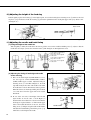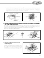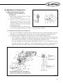
1
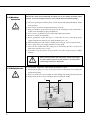
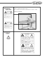
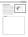
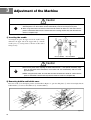
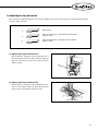
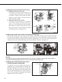
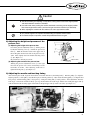
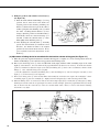
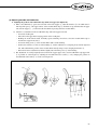
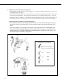
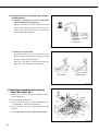
User’s
Manual
KM-757
High speed, two needle, drop
feed, needle feed, sewing
machine with automatic
thread trimmer.
KM- 797
High speed, two needle, drop
feed, needle feed, sewing
machine with automatic
thread trimmer for each
needle.
1. For proper use of the machine, thoroughly
read this manual before use.
2. Keep this manual in a safe place for future
reference in case the machine breaks down.
SUNSTAR MACHINERY CO., LTD.
MME-050629
lity
a
u
tQ
Besst Pricevice
Be st Ser
Be
Thank you for purchasing our product.
The upgraded KM-757 km-797 Series, built on valuable technology and
experience drawn from years of production of automatic thread trimming sewing
machines, features new FORTUNA AC SERVO automatic thread trimming motor
designed to fully realize the Mechatronics of the sewing machine industry.
This model guarantees to satisfy increasingly growing and
sophisticated needs of the sewing industry by offering diverse functionalities,
excellent performance, remarkable power, enhanced durability and refined design.
Read all instructions in this manual thoroughly before proceeding with operation of the
sewing machine to achieve maximum performance.
Note that specifications of this product may be changed at any time without
prior notice for performance improvement.
SUNSTAR MACHINERY CO., LTD.
Table of Contents
Safety rules for machines ..................................................................................................................................... 4
1. Specification
1) Sewing machine ......................................................................................................................................................... 8
2) Servo motor ................................................................................................................................................................ 9
3) 470 motor ................................................................................................................................................................... 9
4) 470 motor controller ................................................................................................................................................... 9
5) Clutch motor (for non-trimming type) ...................................................................................................................... 9
6) Peripheral automation devices (optional) .................................................................................................................. 9
2. Installation
1) Installation of the machine head .............................................................................................................................. 10
2) Installation of knee lifting solenoid and power switch box .................................................................................... 10
3) Oil supply ................................................................................................................................................................. 11
4) Adjustment of belt tension ....................................................................................................................................... 12
5) Installation of the program unit (Servo motor) ....................................................................................................... 12
6) Installation of the belt cover .................................................................................................................................... 12
7) Installation of the thread stand ................................................................................................................................. 13
8) Assembly of the location detector and its control method ..................................................................................... 13
9) Check for the stop position of the sewing machine (automatic thread trimmer) ................................................... 14
10) Reverse button function (automatic thread trimmer) ........................................................................................... 15
3. Adjustment of the machine
1) Inserting the needle .................................................................................................................................................. 16
2) Removing bobbin and bobbin case ......................................................................................................................... 16
3) Winding the lower thread ........................................................................................................................................ 17
4) Routing the lower thread ......................................................................................................................................... 17
5) Inserting the bobbin ................................................................................................................................................. 18
6) Routing the upper thread ......................................................................................................................................... 18
7) Adjusting the thread tension .................................................................................................................................... 19
8) Adjusting the height and pressure of the presser foot ............................................................................................. 21
9) Adjusting the needle and feed dog timing ............................................................................................................... 21
10) Adjusting the height of the feed dog ..................................................................................................................... 22
11) Adjusting the needle and hook timing ................................................................................................................... 22
12) Clearance adjustment between the upper side of the hook stopper and the upper side of needle plate groove ..... 23
13) Clearance adjustment between the hook and opener ............................................................................................ 23
14) Operation of needle bar (left, right) stop (KM-797 series) ................................................................................... 24
15) Adjusting oil flow in the hook and the face plate ................................................................................................. 24
16) Adjusting the trimming device .............................................................................................................................. 25
17) Replacing movable knife and fixed blade ............................................................................................................. 30
18) Adjusting the wiper ................................................................................................................................................ 31
19) Replacing the gauge set for needle width ............................................................................................................. 32
4. Causes of trouble and troubleshooting
1) Sewing machine troubleshooting ............................................................................................................................ 33
5. Table drawing ....................................................................................................................................................... 35
Safety Rules for Machines
Safety labels in the manual are categorized into danger, warning and caution.
Failure to follow the safety rules may result in physical injuries or mechanical damages.
The safety labels and symbols are defined as follows.
[The meaning of the safety labels]
Danger
Instructions here shall be observed strictly.
Otherwise, the user will be killed or suffer severe physical injuries.
Warning
Instructions here must be observed, or the user could suffer fatal or severe physical
injuries.
Caution
Instructions here should be observed, or the user could face physical injuries or
mechanical damages.
[The meaning of symbols]
This symbol means a must-not.
This symbol means a must for safety.
This symbol means that an electric shock may be caused if the
instruction is not followed properly.
4
1-1) Machine
mobilization
Danger
1-2) Machine
Installation
Caution
Only personnel with a full understanding of the safety rules should move the
machines. The following directions must be observed when delivering the machines.
ⓐ At least two persons should work together.
ⓑ In case the machine should be transported, please wipe the oil covered on the machine
to prevent accidents.
Because physical damage such as the functional obstacles and breakdowns are
likely to occur according to the environment in which the machine is being installed.
Therefore, the following preconditions should be fulfilled.
ⓐ Please keep the order from top to bottom when unpacking the package. Especially,
mind that the nail on the boxes.
ⓑ Because machines are apt to be contaminated and corroded by dust and moisture, you
should install the climate controller and should clean the machines regularly.
ⓒ Keep the machines out of the direct rays of the sun.
ⓓ Keep both sides and the backside of the machines off at least 50cm from the wall to
secure enough space to repair.
ⓔ Danger of Explosion
Don’t run the machine near the places with the dangers of explosion.
Don’t run the machine near the places with the dangers of explosion, including the
places where the spraying product like aerosol are used in large quantities or oxygen
are dealt with, unless the exact actions concerning the operation are guaranteed to
avoid the explosion.
ⓕ Because of the peculiarity of the machine, any illuminators are not equipped. So,
users should install the lighting apparatus around the working area.
[Note] The details about the installment of the machine are described in No. 2
Installations.
1-3) Troubleshooting
Danger
In need of troubleshooting, it should be done by the trained A/S engineer of our
company.
ⓐ Ahead of cleaning and repair, be sure to shut off the power supply. And wait for about 4
minutes till the machine discharges completely.
ⓑ Even a part or all of the machine should not be modified without any consultation with
our company
ⓒ In case of repair, you should change the damaged part into the standard article of our
company
ⓓ After repair, please put again the safety cover disjointed while repairing
5
1-4) Machine
Operation
Warning
KM-757/797 series are manufactured for industry use to sew textiles and other similar
material. In case of running the machine, users should observe the following things.
ⓐ Ahead of operating the machine, please read the manual and understand fully the details
on its operation.
ⓑ Don’t forget to put on the garment suited for the safe work.
ⓒ Keep your hands or a part of the body away from the running part of the machine like a
needle, hook, thread take-up spring and pulley etc.
ⓓ Don’t remove any kind of cover for safety while running the machine.
ⓔ Be sure to connect the earthed line.
ⓕ Before opening the electric box such as a control box, be sure to shut off the power
supply and make sure that the power switch should be put on“off.”
ⓖ When threading the needle or before checking after sewing, be sure to stop the machine.
ⓗ Don’t switch on the power supply with the foot on the pedal.
ⓘ Don’t run the machine when the cooling fan are not running. Be sure to clean the air
filter in the control box once a week.
ⓙ If possible, keep off from the strong electronic wave like a high frequency welding
machine
Warning
1-5) Safety Device
Warning
Always start the machine with safety covers in place since fingers
or hands could be injured or cut off by the belt. Turn off the power
switch during check-ups or adjustments.
ⓐ Safety Label: Suggestions while running the machine are stated.
ⓑ Thread take-up spring cover: the device to prevent the human body from touching the
thread take-up spring.
ⓒ Belt cover: the device to prevent hands, feet and clothing from getting jammed by the belt
ⓓ Finger guard: the device to prevent fingers from contacting the needle.
ⓑ
ⓐ
ⓒ
ⓓ
6
1-6) Position of
Caution Mark
CAUTION
경 고
“Caution”is attached to the machine for safety.
In case of starting to run the machine, read the directions of“Cautions”carefully.
[Position of Caution Mark]
Do not operate without finger guard and
safety devices. Before threading, changing
bobbin and needle, cleaning etc. switch off
main switch.
손가락 보호대와 안전장치 없이 작동하지
마십시오.
실, 보빈, 바늘교환시나 청소전에는 반드시
주전원의 스위치를 꺼 주십시오.
CAUTION
경 고
Hazardous voltage will cause injury.
Be sure to wait at least 360 seconds before
opening this cover after turn off main switch
and unplug a power cord.
고압 전류에 의해 감전될 수 있으므로 커버를
열 때는 전원을 내리고 전원 플러그를 뽑고
나서 360초간 기다린 후 여십시오.
1-7) Content of
“Caution”
Caution
CAUTION
경 고
Do not operate without finger guard
and safety devices. Before threading,
changing bobbin and needle, cleaning
etc. switch off main switch.
손가락 보호대와 안전장치 없이 작동하지
마십시오.
실, 보빈, 바늘교환시나 청소전에는 반드시
주전원의 스위치를 꺼 주십시오.
CAUTION
경 고
Hazardous voltage will cause injury.
Be sure to wait at least 360 seconds
before opening this cover after turn
off main switch and unplug a power
cord.
고압 전류에 의해 감전될 수 있으므로 커버를
열 때는 전원을 내리고 전원 플러그를 뽑고
나서 360초간 기다린 후 여십시오.
7
1
Specification
1) Sewing machine
No
1
Model No
Model Name
KM-757
High-speed, two needle, drop feed, needle feed, standard hook sewing machine
2
KM-757-7S
High-speed, two needle, drop feed, needle feed, standard hook sewing machine with automatic thread trimmer (Servo motor)
3
KM-757-7N
High-speed, two needle, drop feed, needle feed, standard hook sewing machine with automatic thread trimmer (470 motor)
4
KM-757BL
High-speed, two needle, drop feed, needle feed, double hook sewing machine
5
KM-757BL-7S
High-speed, two needle, drop feed, needle feed, double hook sewing machine with automatic thread trimmer (Servo motor)
6
KM-757BL-7N
High-speed, two needle, drop feed, needle feed, double hook sewing machine with automatic thread trimmer (470 motor)
7
KM-797
High-speed, two needle each, drop feed, needle feed, standard hook sewing machine
8
KM-797-7S
High-speed, two needle each, drop feed, needle feed, standard hook sewing machine with automatic thread trimmer (Servo motor)
9
KM-797-7N
High-speed, two needle each, drop feed, needle feed, standard hook sewing machine with automatic thread trimmer (470 motor)
10
KM-797BL
High-speed, two needle each, drop feed, needle feed, double hook sewing machine
11
KM-797BL-7S
High-speed, two needle each, drop feed, needle feed, double hook sewing machine with automatic thread trimmer (Servo motor)
12
KM-797BL-7N
High-speed, two needle each, drop feed, needle feed, double hook sewing machine with automatic thread trimmer (470 motor)
Item
Model Name
KM-757
KM-757-7S
KM-757-7N
KM-757BL
KM-757BL-7S
KM-757BL-7N
General to heavy material
Usage
3,000 SPM
Max sewing speed
7 mm
5 mm
Max no. of stitches
33.4 mm
Needle bar stroke
1 mm
Feed dog height
7 mm
Manual
Presser
15 mm
Knee
foot height
13 mm
13 mm
Automatic
DP×5 #22 (#11 ~ #22)
DP×5 # 14 (#11 ~ #22)
Needle
Automatic lubrication
Lubrication
1.6mm ~ 52.4mm
16mm ~ 50.8 mm
1.6mm ~ 38mm
Needle width gauge
Item
Model Name
Usage
Max sewing speed
Max no. of stitches
Needle bar stroke
Feed dog height
Manual
Presser
Knee
foot height
Automatic
Needle
Lubrication
Needle width gauge
8
KM-797
KM-797-7S
KM-797-7N
KM-797BL
KM-797BL-7S
KM-797BL-7N
General to heavy material
3,000 SPM
5 mm
7 mm
33.4 mm
1 mm
7 mm
15 mm
13 mm
13 mm
DP×5 # 14 (#11 ~ #22)
DP×5 #22 (#11 ~ #22)
Automatic lubrication
2.4mm ~ 15.9mm
2) Servo motor
MODEL
VOLT
WATT
HERTZ
SC55-1B
1 phase 110V
550W
50/60 Hz
SC55-2B
1 phase 220V
550W
50/60 Hz
SC55-3B
3 phase 220V
550W
50/60 Hz
PHASE
HERTZ
5 : 50Hz
6 : 60Hz
5 : 50Hz
6 : 60Hz
5 : 50Hz
6 : 60Hz
5 : 50Hz
6 : 60Hz
5 : 50Hz
6 : 60Hz
VOLT
3) 470 motor
PM470
MODEL
1:1
1:1
3:3
PM470
3:3
1:1
3:3
1 : 110V
2 : 220V
3 : 380V
4 : 110V / 220V
5 : 220V / 380V
4) 470 motor controller
PC470
MODEL
PC470
B
001
B
001
VOLT
1 : 110V
2 : 220V
5) Clutch motor (for non-trimming type)
MODEL
HEC-1701
1 phase 220V
250W
50/60 Hz
HEC-1703
3 phase 220V/380V
250W
50/60 Hz
HEC-1705
3 phase 220V
400W
50/60 Hz
HEC-1706
1 phase 220V
400W
50/60 Hz
6) Peripheral automation devices (optional)
(S
: Servo motor E
: 470 motor)
Optional device
Model
Usage
AUTO KNEE LIFTING SYSTEM
SPF-4
A solenoid operating structure where the presser foot gets lifted automatically
with pedal reverse gear stage 1 operation.
PRODUCTION COUNTER
SCOUN-1
A counting device which indicates the completed quantity on the program unit
panel, including added, subtracted, corrected or remaining quantity along with
other performance rates.
MATERIAL EDGE SENSOR
SEDG-1
SEDG-2
A device that senses the edge or thickness of the sewing material to stop the
machine without manual pedaling. Available in two types: SEDG-1 for edge
sensing type and SEDG-2 for thickness sensing type.
9
2
Installation
Caution
▶ Installation of the machine should be performed by a trained engineer.
▶ Any electrical wiring must be performed by a qualified technician or agent.
▶ The machine weighs over 42kg. At least 2 persons should carry out the installing work.
▶ Plug in after the installation is complete. If the operator mistakenly steps down on the pedal
with the pug in, the machine will start automatically and can cause physical injuries.
▶ Connect the ground (earth) wire. An unstable connection may result in an electric shock or
a malfunction.
▶ Place the belt cover on top of the machine.
▶ Use both hands when bending the machine backwards or returning it to the normal position.
Using only one hand can lead to severe hand injuries due to the weight of the machine.
1) Installation of the machine head
Insert the hinge rubber ① into the table and fix the oil fan into the center of the machine head support rubber B ② as in Figure 1 and attach it to
the table. After attaching the machine head hinge ③ to the bed, insert it into the hinge rubber ① and install the sewing machine on the machine
head support rubber A ④ and machine head support head B ②.
Oil fan
[Figure 1]
2) Installation of knee lifting solenoid and
power switch box
(1) When attaching the power switch box ⑥, refer to Figure 2 to make
sure that it is placed at the very center of the solenoid bracket.
(2) After attaching the solenoid onto the table, unfasten the screw ④ to
adjust the center of middle linking bar ① and the center of solenoid
shaft ② in parallel position with the lower side of the table ③. After
the adjustment is over, fasten the screw tightly.
(See Figure 2.): An assembling position diagram can be found inside
the solenoid box.
(3) The presser foot height of the sewing machine can be adjusted after
unfastening the fixing nut ⑤ and then turning the middle linking bar
① clockwise to raise and counterclockwise to lower. After finishing
the adjustment, tightly fasten the fixing nut ⑤.
(4) According to the installation position of knee-lifting solenoid, the
operation noise, operation load and presser foot elevation range may
differ. Please assemble so that the machine will operate smoothly.
10
[Figure 2]
Caution
▶ Plug in only after oil supply is finished. If the operator mistakenly steps on the pedal with
the plug in, the machine will start automatically and can cause severe injuries.
▶ When handling lubricants, wear protective glasses or gloves to avoid contact with your
eyes or skin. Inflammation may be caused otherwise. Never drink lubricants since they
can cause vomiting or diarrhea. Keep out of the reach of children.
▶ Operate the machine only after adding oil when the machine is being used for the first time
or has been left unused for a long time.
3) Oil supply
(1) Installing chip remover magnet
Attach the magnetic chip remover ① that is in the accessory
box to the oil fan. (See Figure 3.)
※ Do not use the magnet for other purposes. Use of the sewing
machine without the magnet may cause malfunction and has
a bearing on the machine’s durability.
(2) Lubricating the oil fan
A. Fill the lubricant up to the“HIGH”mark. (See Figure 3.)
B. The lubricant must be SUNSTAR’s oil provided exclusively
for industrial sewing machines or SHELL’s Tellus C10.
C. If the oil in use is down to the“LOW”mark, fill in to
“HIGH”immediately.
D. Once every two weeks is deemed the appropriate
interval for oil refills.
[Figure 3]
(3) For new machines that have been delivered a long ago or has not been used for a long period of time, open the face plate
and apply the oil spray 2-3 times to friction areas such as the thread take up lever linkage ①, the needle bar ② and the
presser bar ③. (See Figure 4.)
[Figure 4]
11
(4) For trial runs, operate the machine at 1,500 spm for
about 10 minutes at a time. Be sure to check whether the
oil window is being lubricated. (See Figure 5.)
(5) Operate the machine at below 2,400 spm for the first 4-5
days and run the machine at normal speed thereafter to
maintain the sewing machine in optimal condition.
[Figure 5]
4) Adjustment of belt tension
After installing the motor, unfasten the fixing nuts ①, ②
and tension will be created to the belt ④ due to motor ③
falling by gravity. Fasten the fixing nut ① first now and
then fasten the fixing nut ② tightly. (See Figure 6.)
④
[Figure 6]
5) Installation of the program unit
(Servo motor)
(1) Fix the bracket ② onto the program unit ①, using 4
fixing nuts ③.
(2) Then, use 3 fixing bolts ④ to tightly fix the bracket ②,
where the program unit ① has been attached, along with
the back cover. (See Figure 7.)
[Figure 7]
6) Installation of the belt cover
(1) Before attaching the belt cover“A”to the machine body,
assemble in advance the rubber collar ① and washer ②
and fixing nail ③ on the to-be-attached side of the cover
as can be seen in picture“K”of Figure 8.
(2) Attach belt cover“A”onto the machine body as can be
seen on Figure 8. Now, if a bobbin winder is attached on
the table, lay down the machine body on its back and
attach the belt cover“A”.
12
[Figure 8]
(3) Lastly, fasten the belt cover“B”to the table, as can be
seen in Figure 9.
[Figure 9]
7) Installation of the thread stand
As can be seen in Figure 10, fix the thread stand ① to the
table using the washer and nut on the right.
①
[Figure 10]
8) Assembly of the location detector and its
control method
(1) Installation of the location detector
A. Installing on the servo motor (in-built location detector)
A location detector sensor is attached to the back side of
the arm. The appropriate clearance between the location
detector and the pulley is 4.7mm. (See Figure 11.)
[Figure 11]
B. Installing on the 470 motor (external location detector)
After assembling the parts in the numbered order as in Figure 12, adjust the synchronization shaft horizontally such that
the photo film is placed at the center of the photo interrupter as in Figure 13. Then fasten it tightly with two fixing screws
using a hexagonal wrench.
[Caution]
As can be seen on figure 12, make sure that the marks“DOWN”and“UP”face the front when looking from the pulley side.
Film adjustment is completed upon shipment.
Pulley
Speed
Sensor Film
Fixed Bushing
Fixed Washer
Fixed
L Wrench
Synchronization Shaft
Photo Film
Screws
Photo
Interrupter
Location
detector
shaft
Fixed Washer
Synchronization
Shaft Fixing
Screws (2)
ClearanceAdjusting Bushing
[Figure 12]
COVER
PCB Holder
[Figure 13]
13
(2) Adjustment of the location detector
A. For Servo motor (in-built location detector)
Adjust the up-stop position of the needle such that the white carved sign on the pulley ③ is in a straight line with the carved
sign on the arm ④ when the needle has stopped in the air. That adjustment can be made by loosening the pulley’s clamp
screw① on the side with N·U carved signs and moving it sideways. Adjust the down-stop position of the needle such that
the needle is on the point of moving up when the needle bar is at the lowest point. This adjustment can be made by loosening
the pulley’s clamp screw ② on the side with N·D carved signs and moving it sideways. (See Figure 14 & 15.)
Up-Stop
Position
DownStop
Position
[Figure 14]
[Figure 15]
B. For 470 motor (external location detectors)
Turn the pulley manually to position the needle bar at the lowest point about to move back up. Then, loosen the fixed
screws on the film as in Fig. 12 and align the“DOWN”film with the film adjustment baseline and the sensor housing
baseline as in Fig. 16 & 17. Tighten the fixed screws just enough so that the film does not rotate. In the same way, place
the thread take-up lever at the highest point, then loosen the fixed screws again and adjust the“UP”film as in shown the
figure. Be careful that the“DOWN”film A that was tightened before does not move when adjusting the“UP”film.
Film-Adjusting Arrow
WN
DO
Setting Area
Film Adjusting
Base
Setting the film when
the needle is in a upstop position
Setting the film when the
thread take-up lever is at
the highest point
Sensor Base
Sensor Baseline
[Figure 16]
9) Check for the stop position of the sewing
machine (automatic thread trimmer)
Check for the machine stop position after moving the needle up
and down by pushing the reverse button. See whether the carved
sign on the arm and the white carved sign on the pulley are aligned
when the needle is in an up position. If not, adjustment to the
photo film of the location detector or to the location of the
magnetic holder will be necessary since there may be problems
with the trimming. In other words, the needle’s up-stop position
should be identical with the stop position of the needle bar after the
trimming operation, which would signify that there is nothing
wrong with the operation timing of the trimmer. (See Fig. 18.)
(Refer to the explanation about the Adjustment of Location
Detector on page 13.)
14
[Figure 17]
Thread take up lever
up-stop position
Needle
bar
frame
[Figure 18]
10) Reverse button function
(automatic thread trimmer)
Pressing the back tack button or reverse button ① during
forward sewing will start reverse sewing immediately.
When you stop the machine and restart it by stepping down
on the pedal with the reverse button ① already pressed
down, you can perform reverse sewing from the beginning.
When the machine is in a“stop”mode, you can change the
up-down position of the needle bar by pressing the reverse
button. Lightly pressing the button once when the needle is
in a down-stop position will stop the needle bar in a high
position. Pressing the reverse button twice within less than
a second when it is in an up-stop position will stop the
needle bar in a low position. In short, the button delivers
two functions: one for reverse sewing and the other for
converting vertical position of the needle. (See Figure 19.)
[Figure 19]
MEMO
15
3
Adjustment of the Machine
Caution
▶ Always turn off the power when mounting a needle. If the operator mistakenly steps on the pedal
while the power is on, the machine will start automatically and can result in physical injuries.
▶ When using clutch motor, be aware that the motor will continue to rotate for a while even after the
power is switched off due to inertia. Start to work on the sewing machine only after the motor has
come to a complete stop.
1) Inserting the needle
As in Figure 20, place the upper end of the needle closely
adhered to the upper side of the stopper hole ②, with the
needle groove ① facing inward. Fix the needle with a
fixing screw③.
KM-757 SERIES
KM-797 SERIES
[Figure 20]
Caution
▶Turn off the power when adjusting the lower thread tension. If the operator mistakenly steps
down on the pedal while switched on, the machine will start automatically and can cause
physical injuries.
▶When using the clutch motor, be aware that the motor will continue to rotate for a while after the
power is switched off. Start to work only after the motor has come to a complete stop.
2) Removing bobbin and bobbin case
Place the needle ① in the highest position, and then like in Figure 21, open the slide plates ② on the left and right, lift the
bobbin holder ③ to remove the bobbin case ④ and the bobbin ⑤.
[Figure 21]
16
3) Winding the lower thread
(1) Winding the lower thread
A. Push the thread through the hole ① and wind it from
the back to the front of the tension adjusting plate ②.
B. Bring the thread toward the bobbin ③ and wind the
thread around the bobbin about 5-6 times in the
clockwise direction.
C. Push the lever ④ so that the pulley ⑤ will touch the
V-belt, operate the machine.
D. Once the lower thread is wound around the bobbin, the
pulley ⑤ automatically pulls apart from the V-belt.
E. About 80% of the bobbin should be wound with the
lower thread. (See Figure 22.)
[Figure 22]
(2) Adjusting lower thread
a. If the lower thread is not being wound evenly, loosen the screw ⑥ and adjust it by moving it left and right. Then,
tighten the screw again.
b. The lower thread is wound more if the adjusting screw ⑦ is turned clockwise, and less if turned counterclockwise.
c. The tension of the lower thread being wound around the bobbin becomes tighter if the nut ⑧ is turned clockwise and
looser if turned counterclockwise.
4) Routing the lower thread
[Applicable model]
KM-757
KM-757BL
KM-757-7S
KM-757-7N
1. Insert the bobbin ① into the hook ②.
2. Insert the thread through“A”part of the hook ②, and pull
it out from the end of the lower thread tension adjustment
plate ③.
3. The adequate length of the pulled-out lower thread is
50mm.
[Applicable models]
KM-757BL-7S
KM-757BL-7N
[Applicable models]
KM-797
KM-797BL
KM-797-7S
KM-797-7N
1. Insert the bobbin ① into the bobbin case ②. For KM -757-7S and
KM-97-7N, it is crucial to insert the bobbin in the turning direction as
in the picture.
2. Insert the thread through“A”part of the hook ②, and pull it out
from the end of the lower thread tension adjustment plate ③.
3. Pass the pulled-out thread through“B”and“C”of the bobbin case
②, as can be seen on the picture, and hang it onto the lower thread
holding spring ④. Then pull it out through the thread hole ⑤.
4. The adequate length of the pulled-out lower thread is 50mm.
[Applicable models]
KM-797BL-7S
KM-797BL-7N
[Figure 23]
17
5) Inserting the bobbin
Stop the needle ① at the highest position. Following the Figure 24, insert the bobbin (where the thread is rolled onto) or the
bobbin case ② into the hook ③. After laying down the bobbin holder ④, close the slide plates ⑤ on the right and left.
[Figure 24]
Caution
▶ Turn off the power switch when routing the upper thread. If the operator mistakenly presses
down on the pedal while switched on, the machine will start automatically and can cause
physical injuries.
▶ When using the clutch motor, be aware that the motor will continue to rotate for a while after
the power is switched off. Start to work on the sewing machine only after the motor has come
to a complete stop.
6) Routing the upper thread
Place the thread take-up lever to the highest position and hang the upper thread like in Figure 25. The adequate length of
upper thread extending from the needle hole is 50mm for initial sewing.
[Figure 25]
18
7) Adjusting the thread tension
The result of the needlework depends on the sewing conditions such as the sewing material, used thread and stitch length.
So please adjust as desired.
good sewing
upper thread tension is strong while the lower thread
tension is weak.
upper thread tension is weak while the lower thread
tension is weak.
(1) Adjusting the upper thread tension
Like in figure 26, turning the tension adjustment nut of
the thread tension control assembly clockwise makes the
upper thread tension stronger and counterclockwise
makes it weaker.
strong
weak
weak
strong
[Figure 26]
(2) Adjusting the lower thread tension
Like in figure 27, turning the tension adjustment nut ①
of the hook clockwise makes the lower thread tension
stronger and counterclockwise makes it weaker.
weak
strong
[Figure 27]
19
5~10mm
(3) Adjusting the tension of thread take up lever spring
A. Adjusting the thread take up stroke
As in figure 28, loosen the stopper fastening screw
①, and turn the thread take up lever’s spring stopper
② clockwise to make the stroke smaller and counter
clockwise to make it bigger. The thread take up
stroke is normally 5~10mm.
B. Adjusting the thread take up tension
As in figure 28, loosen the screw ③ of the thread
tension control assembly, and insert the driver into
the groove ④ of the thread tension control assembly.
Turn clockwise to make the spring tension stronger
and counter clockwise to make it weaker. The thread
take up spring tension is normally 30~70g.
small
large
weak
30~70g
strong
[Figure 28]
(4) Adjusting the thread release stroke. (for automatic trimming type)
If the upper thread falls out from the needle hole after trimming, check whether the plate ① opens while the trimming is
in action. For the adjustment of plate opening level, put the solenoid ② in action, and adjust by moving solenoid collar
③ back and forth to make the opening of the thread tension adjusting plate ① 0.8 mm. Also, when the thread release
solenoid is not in action, check whether the plates are closely adhered to each other. (See Figure 29.)
about 0.8mm
[Figure 29]
[Caution]
If the plates do not open enough during trimming action even when the assembling is correctly done, check whether or
not the upper thread length adjustment volume, which is at the front of the control box, is low.
(5) Adjusting the auxiliary thread tension control
assembly (automatic trimming type)
As in Figure 30, when the auxiliary thread tension
adjustment nut ① is turned clockwise, the length of the
thread after trimming is short. The other way makes the
thread long. The appropriate length of the upper thread
on the needle after trimming is 35~45mm. (This can
also be done by using the remaining upper thread length
adjustment volume of the control box.)
Smaller
Bigger
[Figure 30]
20
Caution
▶ After disassembling and adjusting a safety device, always place it back to the original position
and check whether it functions as intended.
▶ Use both hands when pushing the machine backward or returning it to the original position.
Due to the weight of the machine, your hand can get stuck in the machine if you should slip.
▶ When adjusting the machine with the switch on, be sure to pay extreme caution.
▶ Only trained engineers must perform troubleshooting or inspection of the machine.
▶ For electrical repair or inspection, consult with qualified technicians or agent.
8) Adjusting the height and pressure of the
presser foot
(1) Adjusting the height of the presser foot
Loosen the pressure adjustment screw ① and the presser
bar bracket fastening screw ②, and lift the presser bar
lifter ③. Make the distance between the upper side of
the needle plate and the lower side of the presser foot ④
7mm. Then, tightly fasten the bracket fastening screw
②. (See Figure 31.)
Be careful not to turn the presser bar.
(2) Adjusting the tension of the presser foot
Turning the pressure adjustment screw ① to the right
increases the presser foot tension, and turning it to the
left makes it weaker. After adjusting, make sure to
tighten the fixing nut ⑤. (See Figure 31.)
about 7 mm
[Figure 31]
9) Adjusting the needle and feed dog timing
After removing the needle, lay down the machine on its back and remove the timing belt ①. Turn the pulley ② to align the
highest position ③ of the pulley’s thread take up lever with the position ④. Then rotate the timing pulley ⑤ to align the bed
base point ⑥ with the timing pulley’s base point ⑦. Hang the timing belt ① in this position. After adjustment, when the
feed dog ⑧ comes down and the needle ⑨ goes up, check whether the needle tip ⑨ matches the needle plate upper side ⑩
at the moment that the feed dog upper side and the needle plate upper side ⑩ match each other. (See Figure 32.)
[Figure 32]
21
10) Adjusting the height of the feed dog
Turn the pulley to place the feed dog ① in the highest point. Loosen the feed dog base fastening screw ② and move the feed
dog base ③ up and down to make the feed dog ① protrude in parallel from the needle plate upper side ④ by about 1 mm.
(See Figure 33.)
about 1 mm
[Figure 33]
11) Adjusting the needle and hook timing
(1) Fixing the height of the needle bar
Turn the pulley to make the needle bar in the lowest position. Loosen the needle bar holding screw ①, adjust so that the
needle bar carved sign ② meets the end of the frame ③ like in Figure 34, then tighten the screw.
Lowest point of needle bar when
using a DP×5 needle.
Cross section of hook edge and
needle center.
Lowest point of needle bar when
using a DP×17 needle.
Cross section of hook edge and
needle center.
757 Series
797 Series
[Figure 34]
(2) Adjusting the timing of hook edge and needle
center crossing
A. First, set the stitch length of (DIAL) KM-757, 757-7,
797, 797-7 types at 2.5mm and KM-757BL, 757BL-7,
797BL, 797BL-7 types at 3.5mm. Adjust the hook gear
fastening screw ① so that like in Figure 35, the hook
edge falls exactly at the center of the needle center when
the needle bar is raised 2.4mm from its lowest position.
When this is done, the hook edge will be placed at about
1~1.5 mm above from the upper shaft of the needle
thread hole.
B. In case of the 797 series, if the height of the left and
right needles are not the same, or if the Figure 35
situation-where the needle bar is raised 2.4 mm but the
hook edge is not placed about 1~1.5 mm from the upper
shaft of the needle thread hole-is not true, loosen the
fixing screw ② of Figure 36, pull out the needle holder,
and adjust the needle holder position fixing screw ① up
and down to set the height of the needle.
22
Hook
edge
[Figure 35]
Lower
Higher
Needle holder
[Figure 36]
C. Adjusting the distance between the needle and the hook edge
Raise the needle from its lowest point so that the hook center meets the needle center. Like in Figure 37, when the
lower shaft of the needle meets the balance point of the hook’s needle guide plate ① (adjust the needle guide form),
adjust the distance between the hook edge and the inner side of the needle groove to 0.05~0.1mm. Loosen ①②③④
of Figure 38 and move the left and right ⑤ of the hook base for adjustment.
Hook edge
Needle
Adhering part
0.05~0.1mm
[Figure 37]
[Figure 38]
12) Clearance adjustment between the upper side of the hook stopper and the upper
side of the needle plate groove
Like in Figure 39, the normal distance between the hook stopper and the upper side of the needle plate groove is 1.3mm.
This distance is adjusted by the thickness of the space washer that lies under the hook. When the hook gear fixing screw ①
is removed for repair or replacement, make sure to put back the space washer that was used originally.
(The thickness of the washer may differ by machine.)
[Figure 39]
13) Clearance adjustment between the
hook and opener
Loosen the opener fastening screw ③ and adjust the opener
② to the right and left so that the distance between the hook
① and the opener ② is 0.2mm when the opener ② is pulled
to its max towards the arrowed direction. (See Figure 40.)
[Figure 40]
23
14) Operation of needle bar (left, right) stop (KM-797 Series)
1. When stopping the left needle bar
Place the needle bar trimming direction lever ① to the L (left) position.
Stop
2. When stopping the right needle bar
Place the needle bar trimming direction lever ① to the R (right) position.
Stop
3. When switching to two needle sewing
Vertically press the needle bar return pressing plate ②. The needle
bar trimming direction lever ① will return automatically.
※ The needle bar trimming direction lever ① can be used even
during operation. However, don’t use this function when the
needle bar is in the highest position. It works safely from the
point when the needle bar is about 3 mm below the highest point.
[Figure 41]
15) Adjusting oil flow in the hook and the
face plate
(1) Hook oil level check
Check whether the amount of oil sprinkled from the
hook for 10 seconds is as is on Figure 42. To adjust the
amount of oil supply, turn the oil supply screw ① on the
hook base to the right to decrease the oil supply, and to
the left to increase the oil supply. (See Figure 42.)
(2) Face plate oil level check
If there is excessive or insufficient amount of oil
provided to the face plate from the thread take up lever
hinge pin, loosen the face plate oil level adjustment
screw fixing nut ② and adjust the face plate oil level
adjustment screw ①. After adjustment, tighten the
fixing nut ②. (See Figure 43.)
Non oxidized oil
White paper
[Figure 42]
[Figure 43]
24
16) Adjusting the trimming device
(1) Adjusting the trimmer driving part
A. Fixing the position of trimming cam
(See Figure 44.)
a) Turn the pulley with hand to place the needle
bar ⑥ at its lowest position.
b) With the left side of the trimming cam ① softly
Lowest
attached to the right side of the lower shaft
point
medium bushing ②, turn the cam to align the
base point ③ with the carve④ in the lower shaft
medium bushing crank.
c) Fasten tightly the trimming cam fixing screws (3)
⑤. Now, turn the pulley with hand to see whether or not the machine turns smoothly.
[Figure 44]
B. Adjusting the stopper pin holder (See Figure 45.)
a) Once the necessary trimming for trimming cam lead is finished, make sure to turn the machine pulley to place the
trimming cam ③ in the right position, so that the roller ① can enter the complementary straight line range ②.
b) Press down the trimmer shake linkage ④ to make the roller ① come inside the trimming cam ③,
Adjust the holder ⑦ to make the right equal point of the roller ① adhere smoothly to the right inside of the
cam’s complementary straight line ②, and the left equal point of the stopper pin ⑥ adhere ⑧ smoothly to the
left inside of the stopper pin holder ⑦. Once this is done, tightly fasten the fixing screw ⑨.
Once such adjustments are made, the trimmer shake linkage ④ will not move even when shaken to its sides
(the roller is inside the cam). Make sure to check if the shake linkage ④ returns to its original position ⑩
quickly and smoothly when released. If not, proceed with horizontal adjustment of stopper pin holder ⑦.
complementary
straight line
trimming finishing point
movable knife operation
starting point
Trimming cam lead
※ The present cam stop position: still inside the
complementary straight line of cam leading, right
before the roller drops out upon finishing trimming.
[Figure 45]
25
C. Fixing the position of the trimmer solenoid (ass’y)
(See Figure 46.)
a) When the whole trimmer shake linkage ① is in up
position, that is, when it has come back to its
original position after finishing trimming, the
distance ④ between the lower part of the roller ②
and the equal point of the trimming cam ③ is about
0.8~1mm. Assuming that this distance ④ never
changes, adjust the position of solenoid bracket ⑦
horizontally, where the solenoid housing ⑥ is
attached, to make the solenoid stroke ⑤ 4 mm.
Then, tightly fasten with fixing screw ⑧.
b) After adjusting the solenoid stroke ⑤, manually
operate the solenoid shaft ⑨ towards the arrow
direction. See whether it returns to its original
position fast and smooth when released. If not,
proceed with horizontal adjustment of the
bracket ⑦.
Solenoid
Stroke
[Figure 46]
(2) Adjustment of linking device for movable knife shaft and the trimmer driving part (See Figure 47.)
A. When the previously explained adjustment of trimmer driving part is complete, it is in its normal position where the
trimmer shake linkage ① has returned to its up position after trimming action.
B. First, loosen the fixing screw ② of the movable knife shaft (right), hold the initial assembling angle of the crank
(right) ③ to be about 15°, 30' to the left from the perpendicular line ⒕ drawn to its center ⒔. To make sure that this
position is maintained, adjust the length of the ball joint linking bar ⑤ which comes assembled to trimmer shake
linkage ①. Also, adjust the fixing screw ② tightly.
(※ For the adjustment of the ball joint linking bar ⑤, turn the linking bar ⑤ after loosening the nuts (left) ⑥ and
(right) ⑦. ⑥ is left nut and ⑦ is the right nut.)
C. Then, loosen fixing screw ⑧ of the movable knife shaft crank (left), and in the same angle as the crank(right)’s lower
assembling angle ⑨, place the crank(left) ⑩. Tightly fasten the fixing bolt ⑪ to make sure this position holds.
D. When the linking device is connected as such, the movement angles ⒃⑮⑭⑨ of crank (left) ⑩ and (right) ③ during
trimming movement results in an equal angle movements for left and right, against the perpendicular lines ⒕ and ⒖
that are drawn from the center line ⒔ of the two movable knife shafts. Hence, it can be said that the trimming
movement is very light.
[Figure 47]
26
(3) Adjusting movable and fixed knives
A. Adjusting the position of movable knife-edge and hook stopper (See Figure 48.)
a) When a movable knife ① passes the front side of the hook stopper ②, adjust the distance ④ to be within 0.05~2
mm range like part ③. The upper surface of the movable knife-edge ⑥ should be set up 0.2mm below the upper
side of hook stopper ⑤. (※ Given that the fixed knife is pressing down the movable knife.)
b) Clearance ④ adjustment of the movable knife edge and hook stopper front side
Loosen the needle plate
Place the hook stopper in the hanging position to the needle plate
Holding the hook with the hand, manually operate trimming movement so that the movable knife-edge is
matches the stopper front side ③.
Loosen the fixing screw ⑦ of the movable knife shaft eccentric bushing.
In the lower side hole ⑨ of the eccentric bushing ⑧, stick in a thin driver or adequate pin ⑩ and turn right and
left. This will make the position of the movable knife shaft ⑪ change, hence changing the distance ④.
When the clearance adjustment is finished, tightly fasten the fixing screw ⑦ of the bushing.
c) The adjustment of crossing height ⑫ between the hook stopper upper side ⑤ and movable knife edge upper side
⑥ is possible to certain degree by adjusting the movable knife base washer ⑦ or by changing the position of
movable knife shaft collar ⑧, as can be seen in figure 49.
[Figure 48]
27
B. Adjusting movable and fixed knife (See Figure 49.)
a) Like in Figure 49, adjust the position of the fixed knife ③ so that the fixed knife right side edge ② matches the
movable knife inner side edge ①.
b) The initial assembling position of the movable knife ④ is where the movable knife-edge protrudes about 3 mm
from the edge of the fixed blade. Please check the“final fixing of the movable knife initial position”on page 29.
c) The surface adhesion conditions ⑤ of fixed blade edge and movable knife upper side have huge impact on its
trimming capacity. Please note the various cases of movable/fixed knife surface adhesion conditions on the picture.
[Correcting the adhesive conditions of movable and fixed knives]
Like in Figure 49, operate manual trimming movement with color ink on the movable knife-edge. By checking
the ink trace remaining on the movable knife, the surface adhesion condition of the movable/fixed knives can be
tested.
If the surface adhesion is not very good (same method is used to adjust the tension of movable/fixed knives),
please use the following methods: adjusting the amount and position of the washer ⑦ in the lower side of the
movable knife base ⑥, horizontally adjusting the assembling position of movable knife shaft collar ⑧, and
correcting the shape of fixed blade ⑨ setting position.
[Checking the surface adhesion]
※ Apply color ink on the upper
side of the movable knife-edge
(good)
(bad)
(bad)
[Figure 49]
28
’s initial position (See Figure 50.)
C. Final fixing of the movable knife’
The standard initial assembling position of the movable knife ① is where the movable knife-edge protrudes about
3mm ③ from the fixed blade edge ② when the trimming action is finished, that is, when the movable knife is in its
initial stop position. When fixing the position of the movable knife, the following directions must be followed so that
the power generated in the cam ④ is delivered without any loss to the trimming action.
[Adjustment Order]
ⓐ Manually turn the pulley to finish trimming of the trimming cam ④. Place the cam so that the roller can enter the
complementary straight line ⑤.
ⓑ Slightly loosen the fixing screws ⑥, ⑦ of movable knife shaft crank of both the left and the right.
ⓒ Press the trimmer shake linkage ⑧ to enter the roller ⑨ inside the cam. Push the linking bar ⑩ to the right or the
left crank linking rod ⑪ to the left so that there is no excess room in each linking device. When this is done, the
roller ⑨ gets to adhere to the right side of the cam’s complementary straight line ⑤, as can be seen in the picture
⑫. While maintaining this position, adjust to make the movable knives on the right and the left protrude about 3mm
from the fixed blade-edge ②. Now, tightly fasten the crank fixing screws ⑥⑦ on both sides.
ⓓ If the initial position of the movable knives of both sides are to be adjusted slightly, use the ball joint linking bar ⑩.
If only the movable knives are to be adjusted, use the linking rod ⑪.
Trimming cam lead
Movable knife initial assembling position
complementary
straight line
trimming
finish point
starting point of movable
knife movement
[Figure 50]
D. Adjusting lower thread holder (See Figure 51.)
The position of lower thread holder ① is set by
fixed blade ② and bolt ③. Like in the picture,
loosen the bolt ③ and place the lower thread
holder ① edge at the lower side of the movable
knife ④, about 8mm apart from the movable
knife edge ⑤. Make sure to check that the right
and left upper sides ,
of the lower thread
holder is tightly adhered to the lower side of the
movable knife.
[Figure 51]
29
(4) Checkpoints on the assembling status of other
trimming devices
A. Check the starting point of the movable knife
when the trimming action takes place
Operate trimming movement manually to check
whether the thread take up lever is in the lowest or at
least 2.5 mm raised level when the movable knife
starts working, like in Figure 52.
Thread take
up lever’s
lowest point
0~2.5mm
(Point where
the movable
knife starts its
movement)
[Figure 52]
B. Maintenance of fixed blade
When the thread does not get trimmed or if the
trimmed section of the thread is sloppy, please check
the edge condition of the fixed blade.
If the edge of the knife is too dull, sharpen the edge
using oil stone or sand paper. (See Figure 53.)
60。
60。
OIL STONE
SAND PAPER
[Figure 53]
17) Replacing movable knife and fixed
blade (See Figure 54.)
(1) Lift the presser foot ① and open the slide plate lefts ②,
right ③ and front ④.
(2) Disassemble the needle plate ⑤.
(3) Loosen the fixing screw ⑥, to disassemble the washer
⑦, fixed blade ⑧ and lower thread holder ⑨.
(4) Loosen the fixing screw ⑩ and dissemble the movable
knife ⑪.
※ To assemble, follow the reverse order of disassembling.
[Figure 54]
30
18) Adjusting the wiper
about 0.3 mm
about 0.3 mm
about 0.3 mm
[Figure 55]
(1) Set the needle at the up-stop position. (at the needle position on the control after trimming)
(2) Set the stitch length at dial“2”.
(3) When pressing with hand as in the above picture, the wiper edge ① should protrude about 0.3 mm from the needle edge.
Loosen the four clamp screws ② to vertically adjust the solenoid ③.
(4) Hang the thread onto the two needles.
(5) The position of the wiper edge ① should look like the picture ⑤, where the two hooks of the wiper ① can securely hang
the thread. To do so, loosen the clamp screws ④ of the wiper and horizontally adjust the wiper ①.
about 3 mm
[Figure 56]
(6) When the wiper ① is in waiting position, the distance between the wiper edge ① and the presser bar ⑥ equal point
should be about 3 mm. To do so, loosen the clamp screw ⑧ and vertically adjust the stopper ⑦.
※ Depending on the thread type, there are cases where the thread cannot be hung to the wiper edge. Hence, it is
necessary to bring the wiper into the range of the needle where the thread from the sewing material can be
hung. Make sure that the needle fixing screw does not get in the way of the wiper.
0.5~1mm
[Figure 57]
(7) The trace of wiper edge ① is as the above picture. Adjust the wiper edge ① by loosening the clamp screw ④ and
vertically adjusting the distance between the needle edge and wiper to 0.5~1mm.
31
19) Replacing the gauge set for needle width
(1) Disassembling order
[Caution] Turn off the power switch
3. Disassemble the left and right needle holders (KM-797 series)
1. Remove the right and left slide plates.
2. Remove the two needles
3. Disassemble the needle holder.
(※ turn it towards the arrowed direction
for removal: KM-757 series)
4. Lift the presser bar lifter to raise the presser foot
5. Remove the presser foot
6. Remove the needle plate
7. Disassemble the feed dog
8. Lay down the sewing machine.
[Adjusting the left/right hook base]
When replacing with a wider or narrower gauge than the needle
width in use, the hook edge and needle distance may not fit
correctly. In this case, loosen the screws ①,②,③,④ as can be
seen in the picture, and replace the feed dog or adjust the
distance between the hook edge and the needle. Fasten after
making the adjustments.
(2) Assembling order
After assembling in the reverse order of disassembling, adjust the left and right hook base.
32
4
Causes of Trouble and Troubleshooting
1) Sewing machine troubleshooting
No
1
Symptom
Needle breaks
Checkpoints
Root cause
Direction and height of
needle
Needle is inserted into wrong position
Reinsert the needle correctly and push in
to its highest level.
Needle
Needle is bent
Change the needle
Feed dog timing
Bad timing of feed dog
Adjust the timing of feed dog
Gap between needle and Bad timing of needle and hook
hook
The heads of the needle and the hook
interfere each other.
2
3
Thread breaks
Poor thread
adjustment
Corrective action
Adjust the timing of needle and hook
Adjust the location of the hook
Threading method
Wrong threading (inserted from the
opposite side)
Thread the needle correctly
Needle
Bent needle
Change the needle
Direction and height of
needle
Needle inserted in the wrong direction
and height
Insert the needle correctly
Upper thread tension
Too tight upper thread tension
Reduce the tension of upper thread
Lower thread tension
Too loose lower thread tension
Reduce the tension of lower thread
Thread take up stroke
Too large stroke
Adjust the stroke level
Hook
There is a scratch on the hook edge
Remove the scratch on the hook edge
Feed dog
There is a scratch on the needle hole of
the feed dog
Remove the scratch on the feed dog
Needle plate
There is a scratch on the thread case
and around the needle plate
Remove the scratch on the needle plate.
Thread tension
Upper and lower thread tensions are bad
Adjust the upper and lower thread
tensions
Thread take up spring
tension
Thread take up spring tension is
inadequate
Adjust the thread take up spring tension
Gap between opener and The gap between the opener and hook is Adjust the gap between the opener and
inadequate
hook
hook
4
Direction and height of
needle
Needle is inserted into wrong position
Reinsert the needle correctly and push in
to its highest level.
Needle
Needle is bent
Change the needle
Threading
Wrong direction
Insert the thread in the right way.
Hook timing
The timing between the needle and hook
is bad
Adjust the timing between the needle and
hook
Needle and hook are too far apart
Adjust the position of the hook
The length of the remaining upper thread
is too short
Increase the adjustment volume of the
upper thread on the control box
After trimming, lower thread holder does
not hold the lower thread
Adjust the location and tension of the
lower thread holder.
Check the up-stop
position of the needle
Due to problems in the up-stop position
of the needle, the thread take up lever
pulls the upper thread out of the needle
when the sewing starts
Readjust the needle’s up-stop film
position
Check the oil felt tension
of upper thread
The upper thread oil felt is pressing the
thread too strongly.
Adjust the felt tension
Gap between the needle
Upper thread falls and the hook
out when starting Remaining upper thread
to sew or sewing length after trimming
is skipped.
Lower thread holder
33
No
5
6
34
Symptom
Checkpoints
Root cause
The gap between the
movable knife and the
hook
The height and distance between the
Readjust the movable knife setting
movable knife and the hook do not match position
Check the tension of
fixed knife
Tension and contact of movable and
fixed knives are bad
Correct the tension adjustment and
surface contact of movable and fixed
knives.
Direction of the needle
Needle is not inserted correctly
Insert the needle correctly
Blade side of movable
and fixed knives
Scratch and abrasion of movable and
fixed knives
Replace movable knife or fixed knife.
Trimming cam timing
The timing of trimming cam is wrong
Adjust the timing of trimming cam
Thread release stroke
Thread release stroke is too small
Readjust the thread release stroke
Trimming timing
Wrong trimming timing
Adjust the trimming timing
Opening of the thread
tension adjusting plate
The opening on the thread tension
control plate is too small
Adjust the thread release stroke
Tension of auxiliary
thread tension
adjustment assembly
Too strong tension on the auxiliary thread Adjust the tension of the auxiliary thread
tension control assembly
tension control assembly
Thread take up stroke
Thread take up stroke is too large
Adjust the thread take up stroke
Thread release
adjustment volume on
the control box
Volume is adjusted to too low
Increase the volume adjustment.
Trimming miss
Too short thread
length after
trimming
Corrective action
5
Table Drawing
35