1
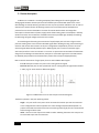
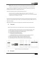
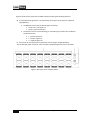
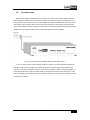
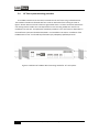
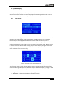
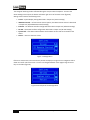
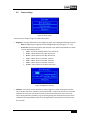
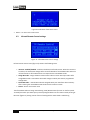
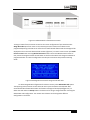
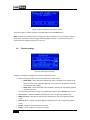
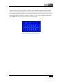
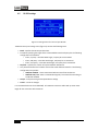
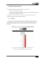
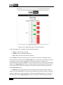
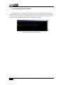
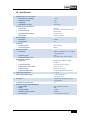
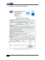
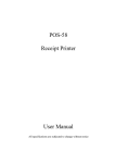
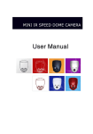
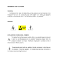
LinkBone Switch
Type: 1-to-15/Dual 1-to-15
User manual
Version 0.9
Copyright © 2014 LinkBone. All rights reserved.
Table of Contents
1.
Safety instructions .......................................................................................................................... 3
2.
Inspection of the instrument .......................................................................................................... 5
3.
Device description ........................................................................................................................... 6
4.
5.
3.1
Front panel .............................................................................................................................. 7
3.2
Rear panel ............................................................................................................................... 7
3.3
Instrument setup .................................................................................................................... 9
3.4
19'' Rack system mounting procedure.................................................................................. 10
System Display .............................................................................................................................. 11
4.1
Main screen........................................................................................................................... 11
4.2
Screen settings ...................................................................................................................... 13
4.3
Infrared Remote Control settings ......................................................................................... 14
4.4
Ethernet settings ................................................................................................................... 16
4.5
RS-232 settings...................................................................................................................... 18
Ethernet remote control port ....................................................................................................... 19
5.1
HTTP server ........................................................................................................................... 19
5.2
Telnet Server ......................................................................................................................... 21
6.
Access through RS-232 interface .................................................................................................. 22
7.
Text commands accepted by LinkBone Switch 1-to-15/Dual 1-to-15 type .................................. 23
8.
Device cleaning ............................................................................................................................. 24
9.
Product recycling .......................................................................................................................... 24
10. Specifications ................................................................................................................................ 25
11. Appendix A - Electromagnetic Compatibility ................................................................................ 26
2
LinkBone Switch User manual, 1-to-15/Dual 1-to-15 type
1. Safety instructions
The user should get familiar with safety requirements and operating instructions before turning
on the device for the first time to prevent personal injury or damage of equipment. The
manufacturer does not take responsibility for any instrument damages or personal injuries caused
by not restricting the device operation instructions and specifications.
The LinkBone Switch must be only used with the power adapter provided by the manufacturer. The
device should be operated at temperature range from 0 to 40 °C and low humidity environment.
Ensure adequate air circulation to prevent overheating of the device. During operation the device all
its components must be always dry and used in an atmosphere free of conductive pollution. The
operating atmosphere should not contain explosive and corrosive gases. In case of suspected device
failure or any other hazardous situation the user should immediately stop the operation of the
device. Keep all elements of the system away from children.
The device should not be exposed to direct sunlight. In case of spilling liquid on the equipment,
immediately disconnect the power supply and discontinue its use.
During installation please note that device housing and all connectors are connected to the negative
rail of the power supply adapter (marked as "-" or ground on the 12VDC connector). Do not short the
device ground to elements with different electric potential (e.g by connecting device housing or
external cables). Touching device ground and elements with the different electric potential can
result in electric shock.
In order to connect external equipment to LinkBone Switch the user should always check the
electrical and mechanical compatibility of the devices. The specified voltage and current values for
the connectors cannot be exceeded. In case of incompatibility of electrical or mechanical properties
devices should not be connected.
When connecting external equipment to ports with labels from A to P please use proper protection
against signal reflections, electrostatic discharge and other intended or unintended(e.g. by device
failure) short circuits with other port lines or ground. Make sure that cables being connected to the
device are previously discharged to prevent damage of the equipment from ESD. It is not
recommended to use LinkBone Switch with sensible equipment which can be damaged by
unexpected electric signals or short circuits. The manufacturer is not liable for any equipment
damage resulting from not using suitable protection circuits or improper use of the LinkBone Switch.
To reduce probability of device failure because of external noise sources shielded cables should be
used. Please use proper overvoltage protection to prevent damage of the equipment (e.g by
lightning strike). Use only fuse types specified for given device.
Do not operate the unit with the cover or any part of casing removed. When the power supply is
connected to LinkBone Switch do not touch elements with high voltage.
To change the batteries in IR remote control please remove the bottom battery cover. Replace the
batteries according to the drawing under the battery cover. Please pay attention to the battery
LinkBone Switch User manual, 1-to-15/Dual 1-to-15 type
3
polarities and type. Insert the battery cover. The manufacturer is not liable for damage to the
remote control because of badly inserted batteries.
The device LinkBone Switch fulfills the requirements of European Union directives for conducted and
radiated emissions, as specified in the appendix of this manual. Connecting external high amplitude
or high frequency signal sources to LinkBone Switch ports may increase the emissions level of the
device to the value which does not comply with EU directives. Therefore, the user is obligated to
check if conducted and radiated emission levels were not exceeded after connecting external signal
sources and receivers to the LinkBone Switch ports. If emission requirements are not met the user
should tune the signal sources to reach an acceptable level of the EM emission.
If guarantee seals are broken or removed the manufacturer is not responsible for secure and proper
operation of the device. All repair or servicing activities should be performed only by authorized
service centre. Care should be taken to avoid mechanical damage of the unit during transport. Do
not faulty or damaged device.
In order to ensure safe and fault free operation of the device it is recommended to do the inspection
of the unit once a year by an authorized service center.
The manufacturer reserves the right to modify or completely change the operating instructions and
specification of the device at any time. The latest version of documentation can be found at
www.LinkBone.com.
Manufacturer:
ZUH Kamserwis
PL98-400 Wieruszow
ul. Kasztanowa 4
tel. +48 601 743 537
4
LinkBone Switch User manual, 1-to-15/Dual 1-to-15 type
2. Inspection of the instrument
After receiving the unit please inspect if the shipping container is not damaged and the check
the completeness of the delivery. In case of mechanical or electrical damage please contact the sales
representative. The responsibility for device damages during the delivery is held by sender or carrier
side. The manufacturer is not liable for defects caused during transport. In case of damage of
shipped goods please keep the complete shipping container and filling.
Before the first run of the device please check that none of the instrument elements are damaged or
defective. Pay special attention inspecting the power adapter supplied with the unit to avoid electric
shock. In case of finding defect please contact sales representative.
Packing list:
-
LinkBone Switch, 1-to-15 type
AC wall adapter 12V/1000mA
Infrared remote control
Two mounting brackets for 19" rack installation with screws
Self adhesive rubber feet for placing the device on a flat surfaces
User manual
LinkBone Switch User manual, 1-to-15/Dual 1-to-15 type
5
3. Device description
LinkBone 1-to-15 Switch is an analog multiplexer/switch designed for switching digital and
analog signals between common port P and set of fifteen ports marked with letters from A to O.
Gold cladding on internal switching contacts ensures very low resistance and failure rate. In order to
maximize the contact life time all switching contacts are cut off from external atmosphere to
prevent from corrosion and oxidation. The state of internal switches does not change after
interruption or disconnection of power supply which allows limiting power consumption in standby
mode to minimum. The architecture of LinkBone instruments provides high reliability of switching
for wide range of signal voltage levels and current values.
The block diagram illustrating the connection of input/output ports is shown in figure 1. Each
port with marking from A to O includes individual signal switch allowing shorting or disconnecting to
common node P. Each switch state is set by user configuration independently. All lines can route
electrical signals bidirectionally between ports. Meaning that port P can be connected to signal
source and ports from A to O to receivers or vice versa. To prevent the accumulation of electrostatic
charge that can damage connected devices, each port is connected to ground via a 5.1 MΩ resistor.
For detailed port parameters and characteristics please refer to chapter 10 (Specifications).
Due to internal construction of signal ports, there are two LinkBone Switch types:
1-to-15: each port contains only one line for routing electrical signals
Dual 1-to-15: each port has two symmetrical lines for routing electrical signals with numbers
1 and 2 (e.g. for stereo audio or differential signals)
-
Figure 1: LinkBone Switch 1-to-15 internal port connection diagram.
The device operates in two port switching modes:
single – only one out of A to O ports can be connected to common port P at the same time.
In this configuration the device operates as a classic analog multiplexer/demultiplexer. To
protect connected instruments from short circuit during switching all ports are disconnected
before change of switch state.
multi – there is no limit of ports connected to node P. Meaning that more than one port can
be connected to port P at the same time.
-
-
6
LinkBone Switch User manual, 1-to-15/Dual 1-to-15 type
NOTE: because several ports can be shorted together during operation of switch proper
protection circuits/techniques are needed to avoid damage of connected equipment.
The port connection configuration can be done via touch screen located on the front panel or
remotely via Ethernet, RS-232 or infrared remote control.
The access via Ethernet interface is possible by following services::
-
HTTP server with user configuration page described in chapter 5.1 (HTTP server)
Telnet server accepting text commands described in chapter 7 (Text commands accepted by
LinkBone Switch 1-to-15/Dual 1-to-15 type)
The switch control via RS-232 interface is done by using text commands with syntax similar to the
Telnet server commands described in chapter 7 (Text commands accepted by LinkBone Switch 1-to15/Dual 1-to-15 type).
Additionally the switch status can be configured by included RC5 infrared remote control.
3.1
Front panel
Figure 2 shows the front panel of the LinkBone Switch containing the following elements:
1)
2)
3)
4)
power switch (position I means that power is on and O indicates that power is off)
status indicator, the blue color indicates that the device is ready for operation
infrared Remote Control (RC) sensor with RC5 decoder
reset button with the following functions:
• single button press disconnects all ports
• holding down button for 5 seconds starts touch screen calibration procedure
5) RS-232 port described in chapter 6 (Access through RS-232 interface)
6) Ethernet port described in chapter 5 (Ethernet remote control port)
7) System Display with touch screen described in chapter 4 (System Display)
Figure 2: Front panel of the LinkBone Switch.
3.2
Rear panel
LinkBone Switch User manual, 1-to-15/Dual 1-to-15 type
7
Figure 3 shows the rear panel of the LinkBone Switch containing the following elements:
8) A to P bidirectional signal ports. The specification of the ports can be found in chapter 10
(Specifications).
a. The BNC port version has the following pin connections:
Center nut – port signal line
Shield – ground connection
b. The XLR port version has the following pin connections(pin numbers are included on
the XLR connector):
1 - ground connection
2 – positive signal line
3 – negative signal line
9) fuse socket, for fuse replacement type please refer to chapter 10 (Specifications).
10) 12V DC input power connector, refer to chapter 10 (Specifications) for more information.
Figure 3: Rear panel of the LinkBone Switch.
8
LinkBone Switch User manual, 1-to-15/Dual 1-to-15 type
3.3
Instrument setup
Before powering the LinkBone Switch please place it on a flat, stable and dry surface. Stick the
four self adhesive rubber feet on the bottom surface of the device housing. Ensure that there is no
access to the unit by children. Insert the power adapter DC plug into 12VDC socket on the rear panel
of the device. Set the power switch on front panel into O position. Please make sure that used AC
power outlet fulfills the power requirements described in chapter 10 (Specifications). Plug the power
adapter into your AC power outlet. Figure 4 shows the power connection diagram.
.
Figure 4: Connection of the LinkBone Switch to the power outlet.
To turn on the unit set the power switch position on position. The status indicator will light up
red. After a few seconds the light color should change to blue indicating the device readiness for
operation. The system display will show the main screen described in chapter 4 (System Display). If
the status indicator will not light up after power on please check the fuse on the rear panel. In case
of error message printed on the System Screen please contact your local sells representative in order
to analyze the problem.
LinkBone Switch User manual, 1-to-15/Dual 1-to-15 type
9
3.4
19'' Rack system mounting procedure
The LinkBone Switch can be mounted in a standard a 19" rack frame using included brackets.
The instalation handles are fastened with four screws on both sides of the housing as shown in
figure 5. Please make sure that all screws are tightened at there is no loose connection between the
unit housing and the handle. Four oval shaped holes on the mounting handles are used for unit
installation into rack rails. The equipment installation procedure in 19” rack frames is dependent on
the used frame system and should be described in rack installation instructions. Installation of the
LinkBone Switch in 19" rack should be performed only by adequately qualified personnel.
Figure 5: Installation of LinkBone Switch mounting handles for 19” rack systems.
10
LinkBone Switch User manual, 1-to-15/Dual 1-to-15 type
4. System Display
The System Display is located on front panel of the LinkBone Switch. The user can control device
state via touch screen interface. Do not use sharp objects for interacting with the touch screen to
avoid scratches or damage of the touch layer.
4.1
Main screen
Figure 6: The main screen
The main screen (figure 6) shows the current state of the port connections and the mode of
operation. Lines drawn between filled boxes with port name label represent port connections.
Disconnected ports are displayed with boxes with no fill. To modify connections tap on the
connection state illustration. The screen with A to O buttons representing ports (figure 7) will be
displayed. Highlighted key means that the port is connected to the common node P. Buttons with no
fill mean that the port is disconnected. Changing the port status is done by taping the button with
the port letter. The update of internal switches is done immediately after the button is released. To
return to the main screen select the ↵ key.
Figure 7: The switch state configuration screen.
The information about currently selected switching mode is displayed in lower left corner of main
screen. The switching mode operation is described chapter 3 (Device description). By taping on mode
button user can select two switch configurations:
•
•
single mode – indicates that the device is operating in single mode
multi mode – indicates that the device is operating in a multi.
LinkBone Switch User manual, 1-to-15/Dual 1-to-15 type
11
The change of switching mode is reflected during the next port switch sequence. To access the
device Settings menu tap on the button on bottom right corner of the main screen (figure 8).
Settings menu contains the following items:
•
•
Screen – System Display settings described in chapter 4.2 (Screen settings)
IR Remote Control – infrared remote control options, The RC5 IR remote control is described
in chapter 4.3 (Infrared Remote Control settings)
Ethernet – the Ethernet interface configuration described in chapter 4.4 (Ethernet settings)
RS-232 – the RS-232 interface configuration described in chapter 4.5 (RS-232 settings)
System info – information about software and hardware version and serial number of the
device
Return – returns to the main screen
•
•
•
•
Figure 7: Settings Menu
If there are more items in the menu than is possible to display on single screen a navigation slider is
drawn on the left side of the screen. The user can navigate between menu pages using the arrow
keys on the slider (figure 8).
Figure 8: Second part of the Settings Menu
12
LinkBone Switch User manual, 1-to-15/Dual 1-to-15 type
4.2
Screen settings
Figure 9: Screen menu.
The Screen menu shown on figure 9 includes two options
•
Brightness – settings related with screen brightness (figure 10) including the following elements:
o Slider for adjusting the brightness of the backlight display by pressing the + or - keys.
o Screen off control specifying after what time the screen will be switched off. This option
can have the following values:
never – the screen backlight will be never switch off
10 sec – switch off the screen after 10 seconds
30 sec – switch off the screen after 30 seconds
1 min – switch off the screen after 1 minute
2 min – switch off the screen after 2 minutes
5 min – switch off the screen after 5 minutes
10 min – switch off the screen after 10 minutes
Figure 10: Brightness settings.
•
Calibrate – starts touch screen calibration procedure (figure 11). After selecting this item the
user is asked to tap on the calibration points marked with + symbol. The incorrect or inaccurate
calibration of the screen may cause erroneous responses from the touch screen. If an error
occurs during calibration procedure (e.g. by touching wrong point location) the process can be
repeated by selecting Calibrate option or by holding down the reset button on the front panel
for 5 seconds.
LinkBone Switch User manual, 1-to-15/Dual 1-to-15 type
13
Figure 10: Calibration of the touch screen.
•
Return – to return to the main menu.
4.3
Infrared Remote Control settings
Figure 11: Infrared Remote control settings
Infrared remote control menu (figure 11) contains the following items:
•
IR access: enabled/disabled – Enables or disables the infrared receiver. When the receiver is
turned on, the switch state changes after successful decode of received RC5 code. When the
infrared receiver is off the device does not respond to the received RC5 codes.
Assign RC5 code – assigns the RC5 remote control code to current switch port state. After
assigned RC5 code is received the device will change its switch port state to programmed
configuration.
Delete RC5 code – remove RC5 code with assigned switch port state from device memory.
After receiving the removed RC5 code the device will not alter its state.
Return – Return to the main menu
•
•
•
The Infrared RC5 codes are being received using an RC (Remote Control) sensor on the front panel.
To modify the switch port status press previously assigned button on the remote control pointing at
RC sensor (figure 12). During receive of the infrared signals the status diode is red blinking.
14
LinkBone Switch User manual, 1-to-15/Dual 1-to-15 type
Figure 12: LinkBone Switch infrared remote control.
To assign a button from the remote control to the current configuration of port switches select
Assign RC5 code option from menu. In the next step press the remote control button to be
programmed pointing at the RC sensor. After the successful decode of RC5 code the message will be
displayed on the screen with detected code number (figure 13). To return to main screen press Back
to main screen button. Pressing Back to last menu button returns to IR Remote Control menu. If
user presses the assigned remote control button in the future the switch will change its statstate to
programmed value. The switch configuration includes port connection setup and the switching
mode.
Figure 13: Message about successful assignment of RC5 code.
To delete assigned RC5 configuration form device memory select Delete RC5 code option.
Then pointing with the remote control at the RC sensor press the button to be deleted. After
successful decode of button RC5 code a confirmation message will be displayed (figure 14). To
delete the code select the Accept button. The device will no longer change state after receiving the
deleted RC5 code configuration. The remote control button can be assigned to different
configuration in the future.
LinkBone Switch User manual, 1-to-15/Dual 1-to-15 type
15
Figure 14: RC5 code delete confirmation screen.
To cancel program or delete procedure of the RC5 code select the Cancel button.
Note: The RC sensor exposed to directly sunlight or other of infrared sources can lead to change of
device state. This effect is visible through red blinking status indicator. To avoid this behavior it is
recommended to disable the IR access if not used.
4.4
Ethernet settings
Figure 15: Ethernet port settings.
The Ethernet settings menu (figure 15) contains the following items:
•
Button specifying the Ethernet port mode with two possible values:
o Mode DHCP – device operates in DHCP client mode. The DHCP server assigns the IP
address, subnet mask, and default gateway. In this mode it is not possible to modify
other Ethernet port settings
o Mode static – device works with static IP address, subnet mask, and default gateway
assigned by the user
The device Ethernet mode settings are updated after the pressing the Accept button by user
IP xx.xx.xx.xx – displays IP address specified by the user or assigned by a DHCP server
MASK xx.xx.xx.xx – displays the subnet mask specified by the user or assigned by a DHCP
server
GW xx.xx.xx.xx – displays the default gateway specified by the user or assigned by a DHCP
server
Accept – update of the device Ethernet settings
Cancel – cancel modification of Ethernet settings
•
•
•
•
•
16
LinkBone Switch User manual, 1-to-15/Dual 1-to-15 type
In Ethernet static mode by taping on the IP, subnet mask, and default gateway parameter buttons
the user can modify related setting value. The edit window is shown on figure 16. At the top of the
screen edited parameter is displayed. The user can edit parameter value by using the numerical keys
and navigate between positions by using ← or → buttons. To confirm the changes select Ok button.
Tapping Back button returns to previous menu canceling changes.
Figure 16: Ethernet interface edit screen.
LinkBone Switch User manual, 1-to-15/Dual 1-to-15 type
17
4.5
RS-232 settings
.
Figure 17: Settings menu for the serial port RS-232.
The RS-232 serial port settings menu (figure 17) contains the following items:
•
•
Baud – Specifies the RS-232 port baud rate.
Parameter specifying the length of the transmitted data words and parity bit. The following
configurations are available:
o 8 bits, no parity – 8 bit data word length, no parity bit is transmitted
o 8 bits, odd parity – 8 bit data word length, odd parity bit is transmitted
o 8 bits, even parity – 8 bit data word length, even parity bit is transmitted
Stop bits – specifies the number of stop bits between data words
This parameter defines the hardware control flow mode of RS-232 interface. The following
configurations are possible
o HW flow: disabled – data is transmitted without control flow mechanism
o HW flow: RTS / CTS – data is transmitted using RTS / CTS control flow according to
the RS-232 standard
Accept – accept the changes and update device settings
Cancel – cancel the changes
•
•
•
•
It is recommended to use the shielded M/F all line RS-232 extension cables with up to 10 meter
length for the connection with remote PC.
18
LinkBone Switch User manual, 1-to-15/Dual 1-to-15 type
5. Ethernet remote control port
The LinkBone Switch Ethernet offers the following remote access services:
-
HTTP server with user configuration page
Telnet server accepting text commands described in Chapter 7 (Text commands accepted by
LinkBone Switch 1-to-15/Dual 1-to-15 type)
For proper operation of network services a configuration of Ethernet settings is required. The
configuration is described in chapter 4.4 (Ethernet settings).
5.1
HTTP server
To access HTTP server please type in the address bar the configured IP address of the LinkBone
Switch. Based on device switch mode appropriate user configuration page should be displayed.
Figure 18 shows the webpage in single switch mode operation. Figure 19 shows the page in multi
switch mode.
Figure 18: User configuration page in single switching mode.
LinkBone Switch User manual, 1-to-15/Dual 1-to-15 type
19
.
Figure 19: User configuration page in multi switching mode.
At the top of page there is navigation bar with the following pages:
•
•
•
Switch – switch configuration page
Network – Ethernet settings configuration
Help – Basic information about device operation
The user Switch configuration page shows the port connection schematic. To change the switch
mode of the device, select button with Switch mode label. In single tap on the port status box mode
to change the connection state. The On label means that the connection is enabled. The
disconnected port is indicated by Off label. In the multi mode select port state by using the checkbox
and then click Apply changes key to confirm changes. Detailed information about switching modes
can be found in chapter 3 (Device description). To refresh the information about the device state
select Refresh Status button.
The Network settings page (figure 20) allows changing port mode (Static or DHCP), IP address,
subnet mask, and default gateway. The Ethernet port settings are described in Chapter 4.4 (Ethernet
settings). In DHCP mode, change of IP address, subnet mask and default gateway is not possible. To
accept changes select the Apply changes button. After the update of network settings a message
20
LinkBone Switch User manual, 1-to-15/Dual 1-to-15 type
will be displayed to use the newly configured device new IP address for accessing configuration
page.
Figure 20: The network settings configuration page.
5.2
Telnet Server
To connect to LinkBone Switch Telnet server a client program is needed (figure 21). In the
address bar of the client enter the device IP address and port 23. After successful connection to the
server a welcome message is displayed. The system accepts text commands described in Chapter 7
(Text commands accepted by LinkBone Switch 1-to-15/Dual 1-to-15 type). The number of
simultaneously open client Telnet sessions is limited by the server. All inactive telnet sessions are
closed automatically after 2 minutes in order to save system resources. To keep the session alive
execute one of telnet text commands before the timeout e.g. ping.
LinkBone Switch User manual, 1-to-15/Dual 1-to-15 type
21
6. Access through RS-232 interface
Access through the serial interface RS-232 is done via terminal on remote computer (figure 21).
Before establishing the connection parameters of RS-232 serial interface need to be set as described
in chapter 4.5 (RS-232 settings). The LinkBone Switch accepts text commands described in Chapter 7
(Text commands accepted by LinkBone Switch 1-to-15/Dual 1-to-15 type).
Figure 21: RS-232 remote terminal access.
22
LinkBone Switch User manual, 1-to-15/Dual 1-to-15 type
7. Text commands accepted by LinkBone Switch
1-to-15/Dual 1-to-15 type
List of text commands accepted by LinkBone Switch 1-to-15 and Dual 1-to-15 types:
•
•
•
•
•
•
•
•
•
help – prints the list of available commands
info – prints information about the device
mode <mode> – sets the operation mode of the device
off <ports> – changes the port state to Off (there is no connection to port)
on <ports> – changes the port state to On (port is connected to common port P)
reset – resets the state of all ports to Off (all ports are disconnected)
status – prints information about status of the switch
ping – checks if connection to the device is active by replying 'Pong'
quit – closes current session, this command is only available for a Telnet clients
Remarks:
•
•
•
•
•
All commands are case sensitive.
<mode> parameter can have two values:
o single – only one of A to O ports can be connected to port P. In this mode switch
operates as a classic analog multiplexer.
o multi – more than one A to O port can be connected to port P. In this mode user
should keep in mind that ports in On state are internally connected together.
<ports> parameter species one or more ports with labels from 'a' to 'o' or 'A' to 'O' e.g 'on d'
or 'off A E'. In single mode, on command only accepts one port name at the time.
By default all inactive Ethernet connections are terminated after 120 second timeout. To
keep connection active use one of device commands before timeout e.g 'ping'.
When sending a new command the client should wait for completion acknowledge of the
previous command by receiving appropriate message (e.g. Done.).
LinkBone Switch User manual, 1-to-15/Dual 1-to-15 type
23
8. Device cleaning
Before starting cleaning the instrument disconnect all attached cables. Make sure that power
cable is disconnected. Clean the unit only with a lint
lint-free
free dry cloth. Please take care to not scratch
the display when cleaning.
9. Product recycling
The LinkBone Switch complies with the requirements of RoHS standard concerning the use of
hazardous materials.
The product should be disposed by transferring to the recycling point in accordance with local
law regulations. To obtain information regarding disposal requirements please contact
act your local
authorities.
24
LinkBone Switch User manual, 1-to-15/Dual 1-to-15 type
10. Specifications
•
•
•
•
•
Characteristics of A to P ports:
o Maximum input voltage
o Maximum current
o Impedance
o BNC/XLR pin contact
Internal switch specification:
o Switch type
o Contact material
o
o Expected mechanical life
o Switch time
System display
o Resolution
o Touch screen
IR Receiver
o Accepted codes
o Carrier frequency
Ethernet interface
o Standards
o Connector type
o Supported cable types
RS-232 serial interface
o Baudreate
•
•
o Transmission type
o Transmission control flow
o Connector type
o Supported cable types
Operating temperature
Operating humidity range
•
Fuse type
•
•
Installation in 19-inch rack
AC Power adapter type PSC12R-120
o Input voltage
o Power
o Output Voltage
o Maximum output current
o DC connector
+/-24V
1.5A
50 Ω
gold plated
bistable
gold clad, isolated from external
atmosphere
minimum 108
maximum 10ms
128x64
yes
RC5 standard
38Khz
10Base-T/100Base-TX, Auto-MDIX,
Auto-negotiation
RJ45
STP Cat5E, up to 100m length
9600, 19200, 38400, 57600,
115200
asynchronous, full duplex
RTS/CTS, none
female 9-pin D-sub
D-sub shielded extension cable
0 – 40 °C
<= 90% below 35 °C
<=60 above 35 °C
5x20mm fast blow type, current
rating 500mA
yes
100...240 VAC, 50-60Hz
12W
12VDC
1000mA
Center positive standard
LinkBone Switch User manual, 1-to-15/Dual 1-to-15 type
25
11. Appendix A - Electromagnetic Compatibility
26
LinkBone Switch User manual, 1-to-15/Dual 1-to-15 type