1
cobas b 221 system
Instructions for Use
COBAS, COBAS B and LIFE NEEDS ANSWERS
are trademarks of Roche.
©2009 Roche Diagnostics
Roche Diagnostics GmbH
D-68298 Mannheim
Germany
www.roche-diagnostics.com
cobas b 221 system
Revision History
Manual Version
Software Version
Revision date
Changes
2.0
1.0
May 2003
Launch
not delivered
3.0
1.0
June 2003
3.1
1.02
July 2003
4.0
2.0
March 2004
5.0
4.0
December 2004
6.0
5.0
November 2005
7.0
5.0
March 2006
8.0
6.0
December 2006
9.0
7.0
February 2008
10.0
>7.0
April 2009
cobas Branding
Edition notice
cobas b 221 system
In the course of 2006 the Roche OMNI S system was relaunched under the
Roche Diagnostics professional IVD user brand cobas®.
Systems with a serial number of 5001 or above are cobas b 221 systems.
Systems with a serial number up to 5000 are Roche OMNI S systems.
Every effort has been made to ensure that all the information contained in this
manual is correct at the time of printing. However, Roche Diagnostics GmbH reserves
the right to make any changes necessary without notice as part of ongoing product
development.
Any customer modification to the instrument will render the warranty or service
agreement null and void.
Software updates are done by Roche Service representatives.
Copyright
© 2009, Roche Diagnostics GmbH, all rights reserved
The contents of this document may not be reproduced in any form or communicated
to any third party without the prior written consent of Roche Diagnostics.
While every effort is made to ensure its correctness, Roche Diagnostics assumes no
responsibility for errors or omissions which may appear in this document.
Subject to change without notice.
Roche Diagnostics
Instructions for Use · Revision 10.0
April 2009
1
cobas b 221 system
Brands
COBAS, COBAS B, LIFE NEEDS ANSWERS, ROCHE OMNI, AUTOQC,
ROCHE MICROSAMPLER, COMBITROL and AUTO-TROL are trademarks of
Roche.
Contact addresses
Manufacturer
Roche Diagnostics GmbH
D-68298 Mannheim / Germany
www.roche.com
Edition
Revision 10.0, April 2009
First edition: May 2003
REF/No. 03261395001
Roche Diagnostics
2
April 2009
Instructions for Use · Revision 10.0
cobas b 221 system
Table of contents
Revision History
Edition notice
Copyright
Brands
Contact addresses
Edition
Table of contents
Preface
How to use this manual
Where to find information
Conventions used in this manual
Introduction and specifications
1
1
1
2
2
2
3
5
5
5
5
Part A
1 Safety information
Important information
Operating safety information
A-5
A-6
2 General descriptions
Introduction
General notes
Measurement and calibration procedure
Measurement evaluation
Safety instructions for specific dangers
Handling solutions
Handling electrodes
General notes on the use of the MSS cassette
System description
A-9
A-11
A-13
A-14
A-14
A-15
A-15
A-16
A-18
3 Installation and shutdown
Installation
Shutdown
A-59
A-86
A-86
A-87
A-87
A-88
A-89
A-91
A-92
A-92
A-93
A-94
5 Theoretical foundations
Parameters and calculations
Clinical significance
Roche Diagnostics
Instructions for Use · Revision 10.0
Part B
6 Measurement
Preanalytics
Interferences
Limitations of clinical analysis
Measuring procedure
B-5
B-10
B-17
B-19
7 Quality control
Quality control - general
B-33
General QC concept
B-33
Important information concerning the analysis of QC
measurement results
B-35
Material setup
B-36
QC setup wizard
B-44
QC measurement
B-51
Multirules
B-53
QC consequences
B-55
Remove the QC lock
B-56
QC for Ready (with AutoQC module)
B-57
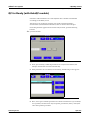
QC for Ready (without AutoQC module)
B-59
QC troubleshooting
B-61
8 Calibration
Calibration - general
Automatic calibrations
User-activated calibrations
Display of parameters during calibration
B-65
B-65
B-66
B-68
9 Software modes
A-27
A-48
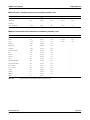
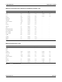
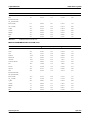
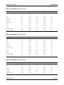
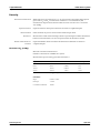
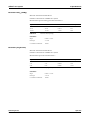
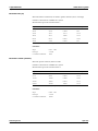
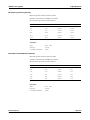
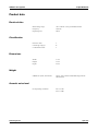
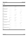
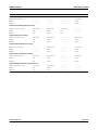
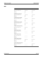
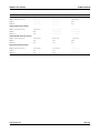
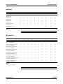
4 Specifications
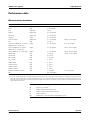
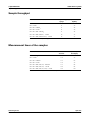
Performance data
Sample throughput
Measurement times of the samples
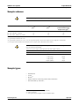
Sample volumes
Sample types
Calibrations
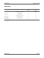
Environmental parameters
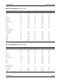
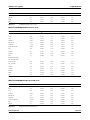
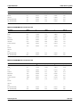
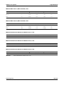
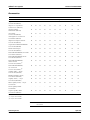
Product data
AutoQC
Printer
Touch screen-PC unit
Barcode scanner
Operation
A-97
A-109
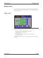
Software modes - general
User interface
Analyzer mode
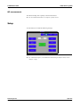
Setup
Data manager
Info
Maintenance
B-71
B-71
B-78
B-80
B-81
B-87
Part C
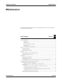
10 Maintenance
Maintenance - general
Decontamination
Daily
Weekly
Quarterly
Sample-dependent maintenance procedures
Unscheduled
Additional maintenance procedures
C-5
C-5
C-7
C-8
C-9
C-13
C-22
C-38
April 2009
3
cobas b 221 system
Troubleshooting
Part D
11 Troubleshooting
Troubleshooting - general
D-5
System stops
D-5
Module stops
D-12
System warnings
D-16
Status messages of measuring and calibration values
D-20
Status messages on the measurement report
D-39
Barcode
D-40
Appendix
Part E
12 List of consumables
Order information
Glossary
Index
Index
Roche Diagnostics
4
E-5
E-9
Part F
F-3
April 2009
Instructions for Use · Revision 10.0
cobas b 221 system
Preface
The cobas b 221 system is an analyzer with integrated AutoQC drawer option.
This manual has detailed descriptions of cobas b 221 system features and general
operational concepts, specification functions and use of controls, operating
techniques, emergency procedures, product labeling and maintenance procedures.
How to use this manual
o
Keep this manual in a safe place to ensure that it is not damaged and remains available for use.
o
This Instructions for Use should be easily accessible at all times.
To help you find information quickly, there is a table of contents at the beginning of
the book and each chapter. In addition, a complete index can be found at the end.
Where to find information
In addition to the Instructions for Use, the following documents are also provided to
assist in finding desired information quickly:
o
cobas b 221 system Reference Manual
o
cobas b 221 system Short Instruction
Conventions used in this manual
Visual cues are used to help locate and interpret information in this manual quickly.
This section explains formatting conventions used in this manual.
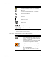
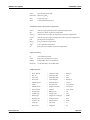
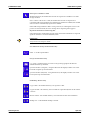
Symbols
Helping to locate and interpret information in this manual the following symbols are
used:
Symbol
Used for
a
Procedural step
o
List item
e
Cross-reference
h
Call up of screen
Note
Roche Diagnostics
Instructions for Use · Revision 10.0
April 2009
5
cobas b 221 system
Symbol
Used for
Caution
All sections / passages that are marked with this symbol describe procedures
and/or indicate conditions or dangers that could damage or lead to a
malfunction in the cobas b 221 system, and which therefore should never be
attempted and contain information that must be observed to avoid potential
injuries (to patients, users and third parties).
Risk of infection
All sections and parts of texts that are marked with this symbol describe
procedures that may involve risk of infection.
IVD symbols
The symbols are used in accordance with DIN EN 980(a) and DIN EN ISO 780(b).
Symbol
Description
Conformité Européenne:
This product complies with the requirements in the guideline for
In Vitro Diagnostic 98/79/EC.
Lot designation
Use by...
The product should not be used after expiry of the specified date.
If a day is not indicated, apply the last day of the respective month.
Temperature limitation
The conditions necessary to preserve the product's shelf life before
opening.
In Vitro Diagnostic Medical Device
Manufacturer
(according to In Vitro Diagnostic guidelines 98/79/EG)
Catalogue number
Serial number (model plate)
Caution, consult accompanying documents
Please consult instructions for use
(a) DIN EN 980: Medical devices - Symbols to be used with medical device labels, labelling and information
to be supplied (Part 1: General requirements)
(b) DIN EN ISO 780: Packaging - Pictorial marking for the handling of goods
Roche Diagnostics
6
April 2009
Instructions for Use · Revision 10.0
cobas b 221 system
Symbol
Description
Biological risk!
(according to the standard IEC/EN 61010-2-101)(a) (Instrument)
Biological risk!
(according to the standard DIN EN ISO 980)(b) (Consumables)
Do not use if package damaged
Do not reuse
Fragile. Handle with care
Handle with care
Valid only for Roche MICROSAMPLER:
Method of sterilization using ethylene oxide
Valid only for BS2 Blood Sampler:
Method of sterilization using irradiation
(a) IEC/EN 61010-2-101: Safety requirements for electrical equipment for measurement, control, and
laboratory use - (Part 2-101: Particular requirements for in vitro diagnostic (IVD) medical equipment).
(b) DIN EN ISO 980: Medical devices - Symbols to be used with medical device labels, labelling and
information to be supplied (Part 1: General requirements).
Other symbols
The following symbols are listed as additional information:
Symbol
Description
Electrodes:
This date indicates the limit of the maximum storage time of
an electrode. The electrode must be installed in the instrument
no later than the imprinted date.
If the installation takes place on the imprinted date, it still falls
within the specifications. The calculation of the “Install
before” date is based on the production date of the elctrode.
Danger symbol: "Irritant" (on the label and the packaging of
S2 Fluid Pack)
Rating: Although not corrosive, momentary, longer-lasting, or
repeated contact with skin or mucous membrane may result in
inflammation. Danger of sensitization during contact with
skin (when classified with R 43).
Caution: Avoid contact with eyes and skin, do not inhale
vapors.
Roche Diagnostics
Instructions for Use · Revision 10.0
April 2009
7
cobas b 221 system
Symbol
Description
Invisible Laser Radiation
Avoid direct radiation to eyes!
Laser Class 3R according to EN 60825-1
P0 ≤ 5 mW
λ = 635 - 850 nm
Store upright
"Grüner Punkt" (in Germany)
Protective gloves, protective goggles and suitable protective
clothing must be worn.
Abbreviations
The following abbreviations are used:
Abbreviation
Definition
A
ANSI
American National Standards Institute
AQC
Automatic Quality Control
B
BG
Blood gas
BUN
Abbr. for blood urea nitrogen
C
CLIA
Clinical Laboratory Improvement Amendments
CLSI
Clinical and Laboratory Standards Institute
cond
Conductivity
CSA
Canadian Standards Association
D
dBA
Decibel weighted against the A-frequency response curve. This curve
approximates the audible range of the human ear.
DIL
Diluent
DNS
Domain Name Server
E
EC
European community
e.g.
exempli gratia – for example
EN
European standard
F
FMS
Fluid mixing system
H
Roche Diagnostics
8
Hct
Hematrocrit
HIV
Human immunodeficiency virus
HW
Hardware
April 2009
Instructions for Use · Revision 10.0
cobas b 221 system
Abbreviation
Definition
I
i.e.
id est – that is to say
ISE
Ion selective electrode
IVD
In vitro Diagnostic Directive
L
LCD
Liquid cristal display
LIS
Laboratory Information System
LJ
Levey Jennings
M
MAC
Media Access Control
MC
Measuring chamber
MSDS
Material safety data sheet
MSS
Metabolite sensitive sensor
MV
Mean value
P
PP
Peristaltic pump
Q
QC
Quality control
R
RCon
Reference contact
REF
Reference solution
S
SIP
Sample inlet path
SDC
Sample distributor cartridge
S1
S1 Rinse Solution
S2
S2 Fluid Pack
S3
S3 Fluid Pack
SCon
Sensor contact
SD
Standard deviation
SO2
Oxygen saturation
T
T&D
Turn & dock
tHb
Total hemoglobin
U
UL
Underwriters Laboratories Inc.
V
VDE
Association of German Electrical Engineers (Verband Deutscher
Elektrotechniker)
e For writing the measuring, calculated and input values see Chapter 9 Softwaremodi >
Parameter on page B-75!
Roche Diagnostics
Instructions for Use · Revision 10.0
April 2009
9
cobas b 221 system
Roche Diagnostics
10
April 2009
Instructions for Use · Revision 10.0
Introduction and specifications
A
1
Safety information . . . . . . . . . . . . . . . . . . . . . . . . . . . . . . . . . . . A-3
2
General descriptions . . . . . . . . . . . . . . . . . . . . . . . . . . . . . . . . . A-7
3
Installation and shutdown . . . . . . . . . . . . . . . . . . . . . . . . . . . . A-25
4
Specifications . . . . . . . . . . . . . . . . . . . . . . . . . . . . . . . . . . . . . . . A-57
5
Theoretical foundations . . . . . . . . . . . . . . . . . . . . . . . . . . . . . . . A-95
cobas b 221 system
1 Safety information
Contents
Safety information
The information provided in this chapter is essential for the safe, trouble-free
operation of the instrument and must be read and understood by the user.
In this chapter
Chapter
1
Important information ................................................................................................... 5
Operating safety information ......................................................................................... 6
Roche Diagnostics
Instructions for Use · Revision 10.0
April 2009
A-3
1 Safety information
cobas b 221 system
Contents
Roche Diagnostics
A-4
April 2009
Instructions for Use · Revision 10.0
cobas b 221 system
1 Safety information
Important information
Important information
These Instructions for Use contain vital warnings and safety information.
This instrument is intended to be used only for the specialized purpose described in
the instructions. The most important prerequisites for use, operation, and safety are
explained to ensure smooth operation. No warranty or liability claims will be covered
if the machine is used in ways other than those described or if the necessary
prerequisites and safety measures are not observed.
The instrument may be operated only by persons whose qualifications enable them to
comply with the safety measures that are necessary during operation of the
instrument.
Suitable protective equipment, like laboratory clothing, protective gloves, protective
goggles and if necessary mouth protectors, must be worn to prevent direct contact
with biological working materials. In addition, a face mask is required if there is a
risk.
Adjustments and maintenance performed with covers removed and power connected
may be attempted only by a qualified technician who is aware of the associated
dangers.
Instrument repairs are to be performed only by the manufacturer or qualified service
personnel.
Only accessories and supplies either delivered by or approved by Roche are to be used
with the instrument. These items are manufactured especially for use with this
instrument and meet the highest quality requirements.
Operation of the instrument with solutions whose composition is not consistent with
that of the original solutions can negatively affect the long-term measurement
accuracy. Deviations in the composition of the solutions can also decrease the service
life of the electrodes.
In order to ensure the quality of the measurement results, complete a quality control
test on 3 levels (low, normal, high) after each electrode exchange, after each exchange
of solutions and packs and after startup of the instrument.
Additionally complete a quality control test on one level between two automatic 2P
calibrations. The level have to be alternated (low, normal, high).
Since the measurements of the instrument depend not only on the correct
characteristic function, but also on a series of marginal conditions (e.g. pre-analysis),
results obtained from the instrument should be submitted for an expert opinion
before taking additional measures based on the supplied measurements.
Caution (refer to accompanying documents)!
Please refer to safety-related notes in the manual accompanying this instrument.
Roche Diagnostics
Instructions for Use · Revision 10.0
April 2009
A-5
1 Safety information
cobas b 221 system
Operating safety information
Operating safety information
The instrument has been constructed and tested according to the following European
Standards:
o
IEC/EN 61010-1
o
IEC/EN 61010-2-101
o
IEC/EN 61010-2-081 + A1
It was delivered from the factory in flawless condition with regards to safety features.
In order to preserve this condition and ensure safe operation, the user must respect
the notices and warnings that are contained in these Instructions for Use.
Roche Diagnostics
A-6
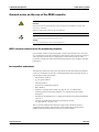
o
This equipment is a Class I laser product, and it complies with FDA Radiation
Performance Standards, 21 CFR Subchapter J (only valid for
cobas b 221<1> system, cobas b 221<3> system and cobas b 221<5> system with
tHb/SO2 module).
o
This instrument is classified under the protection class I according to
IEC /EN 61010-1.
o
The instrument meets the conditions for overvoltage category II.
o
The instrument meets the conditions for contamination level 2.
o
Do not operate the instrument in an explosive environment or in the vicinity of
explosive anesthetic mixtures containing oxygen or nitrous oxide.
o
If objects or liquids enter the internal areas of the instrument, remove the
instrument from its power supply and allow an expert to check it thoroughly
before using it again.
o
The instrument is suitable for long-term operation indoors.
o
The power cord must be plugged into a grounded power receptacle. When using an extension
cord, make sure it is properly grounded.
o
Any rupture of the ground lead inside or outside the instrument or a loose ground connection
may result in hazardous operating conditions for the operating personnel. Intentional
disconnection of the grounding is not permitted.
o
The instrument is not suitable for operation with a direct current power supply. Use only the
original power plug delivered with the cobas b 221 system.
o
The use of controls or adjustments or performance of procedures other than those specified
herein may result in hazardous radiation exposure.
April 2009
Instructions for Use · Revision 10.0
cobas b 221 system
2 General descriptions
Contents
General descriptions
This chapter contains a general description of the instrument, as well as
precautionary measures against special dangers and the proper handling of sensors,
solutions and the MSS cassette.
In this chapter
Chapter
2
Introduction .................................................................................................................... 9
General notes ................................................................................................................. 11
Application area ....................................................................................................... 11
Operating instructions ............................................................................................ 11
Important buttons on the screen ............................................................................ 12
Measurement and calibration procedure ..................................................................... 13
Measurement procedure ......................................................................................... 13
Calibration procedure ............................................................................................. 13
Measurement evaluation ............................................................................................... 14
Safety instructions for specific dangers ........................................................................ 14
Handling samples .................................................................................................... 14
Disposal of waste water, bottles, packs, electrodes and the instrument ............... 14
Decontamination .................................................................................................... 14
Handling solutions ........................................................................................................ 15
Handling electrodes ...................................................................................................... 15
General notes on the use of the MSS cassette .............................................................. 16
MSS cassette removed from the measuring chamber ............................................ 16
Incompatible substances ......................................................................................... 16
Inserting the MSS cassette ...................................................................................... 17
System description ........................................................................................................ 18
Visual identification ................................................................................................ 18
Screen/PC unit ......................................................................................................... 19
Printer ...................................................................................................................... 19
Measuring chamber ................................................................................................. 19
tHb/SO2 module ..................................................................................................... 19
COOX module ......................................................................................................... 20
Pumps ...................................................................................................................... 20
Input unit ................................................................................................................. 20
Roche Diagnostics
Instructions for Use · Revision 10.0
April 2009
A-7
2 General descriptions
cobas b 221 system
Contents
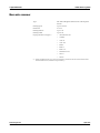
Bottle compartment ................................................................................................ 20
Reverse side .............................................................................................................. 21
Power supply ...................................................................................................... 21
Interfaces ............................................................................................................ 22
Barcode scanner ................................................................................................. 23
Warning and identification labels (incl. nameplate) ....................................... 24
Roche Diagnostics
A-8
April 2009
Instructions for Use · Revision 10.0
cobas b 221 system
2 General descriptions
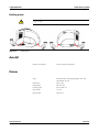
Introduction
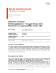
Introduction
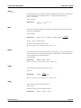
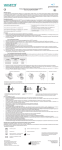
Figure A-1
cobas b 221 system
The cobas b 221 system is an analyzer with integrated AutoQC drawer option.
Depending on combination and configuration, the following parameters can be
measured in whole blood, serum, plasma, acetate and bicarbonate containing dialysis
solutions and QC materials:
o
pH
o
Blood gas BG (PO2, PCO2)
o
Electrolyte ISE (Na+, K+, Cl–, Ca2+)
o
Hematocrit (Hct)
o
Metabolite MSS
Urea/BUN - only cobas b 221<6> system
o
Total hemoglobin (tHb)
o
Oxygen saturation (SO2)
o
Hemoglobin derivative COOX (O2Hb, HHb, COHb, MetHb)
o
Bilirubin (neonatal)
The following configurations are available:
o
cobas b 221<1> system(a)
BG, pH, tHb/SO2
o
cobas b 221<2> system
BG, pH, COOX, Bili
(a)
o
cobas b 221<3> system
o
cobas b 221<4> system
BG, pH, ISE, Hct, COOX, Bili
o
cobas b 221<5> system(a)
BG, pH, ISE, Hct, MSS, tHb/SO2
o
cobas b 221<6> system
BG, pH, ISE, Hct, MSS, COOX, Bili
BG, pH, ISE, Hct, tHb/SO2
(a) are no longer manufactured or offered.
Roche Diagnostics
Instructions for Use · Revision 10.0
April 2009
A-9
2 General descriptions
cobas b 221 system
Introduction
During the measurement or calibration or other processes, it is possible to conduct
database operations, perform certain settings or call up general information at the
same time.
e For details see Chapter 9 Software modes
The individual, mutually independent software modes are defined as follows:
Roche Diagnostics
A-10
o
Analyzer
Measuring, QC measurement, system, calibration,
commonly used functions (quick access)
o
Setup
Instrument settings
o
Database
Data about patients, measurements, calibrations, QC, and
the instrument
o
Info
April 2009
Instructions for Use · Revision 10.0
cobas b 221 system
2 General descriptions
General notes
General notes
Application area
The instrument has been tested for measuring parameters in whole blood, serum,
plasma and dialysis solutions (electrolytes only) and the validity of measurements was
tested accordingly.
In order to achieve accurate measurements of recommended aqueous control
solutions (with regards to deviations from biological samples), choose the proper
components and make the corresponding corrections in the QC measurement mode.
The accuracy of measurement values of undefined aqueous solutions cannot be
guaranteed (e.g. due to the possibility of interfering components and/or missing or
insufficient buffer systems, and/or differences in ionic strength and diffusion
potential when compared to biological samples).
Operating instructions
The cobas b 221 system should be switched on at all times!
If the instrument is switched off for an extended period of time (more than 24 hours),
a shutdown must be performed.
e For additional information, see Chapter 3 Installation and shutdown, section Installation
on page A-27 and Shutdown on page A-48.
Prevent any other liquids from entering the instrument except samples and
QC material at the fill port.
In order to ensure the quality of the measurement results, complete a quality control
test on 3 levels (low, normal, high) after each electrode exchange, after each exchange
of solutions and packs and after startup of the instrument.
Additionally complete a quality control test on one level between two automatic
2P calibrations. The level have to be alternated (low, normal, high).
e For additional information, see Chapter 7 Quality control.
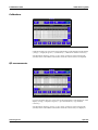
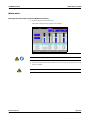
With Software V 6.0 onwards, using cobas bge link, the instrument can be monitored
from one location, any disturbances can be remedied and the analytical quality
monitored.
cobas bge link is a remote monitoring and remote maintenance software for Roche
Point-of-Care analyzers.
e see Figure A-2 on page A-12!
Roche Diagnostics
Instructions for Use · Revision 10.0
April 2009
A-11
2 General descriptions
cobas b 221 system
General notes
B
A
A
"Screen sharing" Symbol
B
"Screen sharing" active
Figure A-2
Confirm the message with [OK] either on the instrument or on the PC. The "screen
sharing" symbol is added in the status line.
To avoid multiple operation of the instrument, the message "Screen sharing active" is
displayed with a yellow background in the error and message window of the
instrument.
As long as the "screen sharing" symbol is displayed in the status line, the service connection is
active. In order to prevent multiple operation of the instrument, no buttons on the screen should be
pressed!
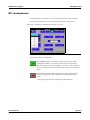
Important buttons on the screen
Buttons
Description
"Analyzer" active / inactive
"Database" active / inactive
"Setup" active / inactive
"Info" active / inactive
e For additional information, see Chapter 9 Software modes, section Buttons on page B-76.
Roche Diagnostics
A-12
April 2009
Instructions for Use · Revision 10.0
cobas b 221 system
2 General descriptions
Measurement and calibration procedure
Measurement and calibration procedure
Measurement procedure
PO2: Use of the Clark measurement principle: measurement of current generated by
the reduction of oxygen.
PCO2: Use of the Severinghouse principle: potentiometric measurement of the pH
change in the electrode caused by CO2.
pH- , Na+-,K+-, Ca2+- und Cl- electrodes are potentiometric electrodes. Special
glasses are used as the sensitive element for pH and Na+. The potassium and calcium
membranes contain special neutral carriers. A special ion exchanger is used for
chloride membranes. Calculation of these variables also requires the use of a reference
electrode—a permanently contacted chloride electrode in the cobas b 221 system.
Glucose, lactate: Glucose oxidizes to form gluconolacton using atmospheric oxygen
and the glucose-oxidase (GOD) enzyme, lactate oxidizes to form pyruvate using the
lactate oxidase enzyme.
The generated H2O2 is determined amperometrically by using manganese dioxide/
carbon electrode at 350 mV.
Urea: Urea is broken into ammonia and carbon dioxide through urease. Ammonia
and carbon dioxide react through hydrolysis with physiological pH to form ammonia
or bicarbonate ions. The ammonia ions can be determined using a potentiometrical
ammonia ion-selective electrode. This measurement requires a reference electrode
such as those used in ion-selective electrodes.
tHb/SO2: Light absorption in whole blood is measured at four different wavelengths,
the sample is subjected to light radiation and the dispersed light is also evaluated.
COOX: The hemoglobin derivatives and the total bilirubin (= neonatal) are
determined spectrophotometrically based on the Lambert-Beer law.
Hematocrit: Measurement of the sample's conductivity in the ISE measuring
chamber.
Calibration procedure
tHb and SO2 was calibrated when the instrument was manufactured.
Oxygen (O2):
PCO2, pH, ISE:
MSS:
COOX:
Roche Diagnostics
Instructions for Use · Revision 10.0
Ambient air and a zero point solution are used to calibrate oxygen.
are calibrated using two solutions mixed under different conditions, thereby avoiding
the gas supply which is required by other instruments.
The calibration is carried out with four (Glu, Lac) or five solutions (Urea/BUN)
whose weighing concentrations form the basis for measured value determination.
Determining the hemoglobin derivatives and the total bilirubin (= neonatal) are
carried out spectral-photometrically using a cuvette.
April 2009
A-13
2 General descriptions
cobas b 221 system
Measurement evaluation
Measurement evaluation
The validity of the test results from the cobas b 221 system must be carefully
examined by a clinical-medical specialist who will take the patient's clinical condition
into consideration before any clinical decisions are reached based on the test results.
In order to ensure the quality of the measurement results, complete a quality control
test on 3 levels (low, normal, high) after each electrode exchange, after each exchange
of solutions and packs and after startup of the instrument.
Additionally complete a quality control test on one level between two automatic 2P
calibrations. The level have to be alternated (low, normal, high).
e For detailed information, see Chapter 7 Quality control.
Safety instructions for specific dangers
Handling samples
While handling samples, all necessary regulations concerning hygiene must be
observed. Dangerous pathogenic agents could be present.
e For more detailed information, see Chapter 6 Measurement
Disposal of waste water, bottles, packs, electrodes and the instrument
Dispose of waste water, bottles, packs, electrodes and the instrument according to local and/or labor
regulations (biologically contaminated—hazardous waste!).
Decontamination
The purpose of this decontamination is to minimize risk when handling items that
were in contact with biological samples.
Roche recommends following a decontamination procedure in addition to
regulations specific to the laboratory.
These decontamination procedures should be performed periodically to minimize the
risk of infections.
Always wear gloves!
e For more detailed information about decontamination, see Chapter 10 Maintenance
Roche Diagnostics
A-14
April 2009
Instructions for Use · Revision 10.0
cobas b 221 system
2 General descriptions
Handling solutions
Handling solutions
Store the cobas b 221 system wash/calibrating solutions according to the specified
packaging requirements. The temperature of the solutions should be adapted to the
ambient temperature before use.
The shelf life of the solutions is limited.
Please read the bottle label and the packaging for the correct storage temperature and
the maximum shelf life.
DO NOT FREEZE!
If frozen, the solution's concentration may change and cause calibration errors!
Do not use damaged fluid packs (S2 and S3)! Do not mix the individual components!
e For "Storage specifications", see Chapter 4 Specifications.
Handling electrodes
Store the electrodes according to the packaging specifications.
The shelf life of the electrodes is limited.
Please read the label and the packaging for the correct storage temperature and the
maximum shelf life.
CAUTION! Installation note for the PCO2 electrode
Insert the electrode into the measuring chamber within 5 minutes of opening the ALU-PE
packaging.
A special protective gas atmosphere designed to condition the PCO2 electrode during storage is
found inside the ALU-PE packaging.
This gas atmosphere ensures immediate potential stability during insertion of the electrode into the
measuring chamber and immediate readiness for measuring the first 2 point calibration.
If more than 5 minutes elapse after opening the ALU-PE packaging, the level of gas conditioning
could be lost and the time required for the first-time calibration could be increased.
e For "Storage specifications", see Chapter 4 Specifications.
Roche Diagnostics
Instructions for Use · Revision 10.0
April 2009
A-15
2 General descriptions
cobas b 221 system
General notes on the use of the MSS cassette
General notes on the use of the MSS cassette
For instrument versions with MSS module only!
Attention:
MSS cassette may only be brought into contact with liquids in the cobas b 221 system while
electrodes are changed!
Replace the MSS cassette within 28 days of installation!
After initial contact with liquids, the MSS cassette may no longer be removed from the instrument.
It may lead to the destruction of the enzyme sensors.
Storage:
At 2 – 8 °C, maximum of 2 weeks at room temperature.
MSS cassette removed from the measuring chamber
Once an MSS cassette is exposed to liquid, it must not be allowed to dry out under
any circumstances since this would destroy the enzymes. The enzymes are equipped
with a special protectant prior to shipping for transportation purposes. This
protectant is washed out inside the instrument during the warm-up phase and MSS
polarization.
Incompatible substances
The following substances may not be introduced into the MSS measuring chamber
under any circumstances since they would immediately destroy the MSS sensors or
severely impact their functionality.
o
Deproteinizer (NaOCl)
o
O2 zero point solution
o
Cleaning solution
o
Na electrode conditioning solution
o
Rinse additive
o
Solutions containing heavy metals (Ag, Hg, Au, etc., e.g. Thiomersal)
o
Cleaning solutions containing detergent (e.g. washing material or liquid
detergents)
o
All solutions for disinfections (e.g. high-percentage alcohol, glutaric dialdehyde,
cresol, etc.)
o
Solutions with pH values that deviate greatly from neutral
(e.g. pH value of < 6.0 and > 9.0)
The use of anticoagulants other than those approved by Roche Diagnostics
(approved: heparin salts), such as EDTA, citrate, NH4 heparin and glycolysis
inhibitor such as NaF and oxalate can lead to erroneous results.
Roche Diagnostics
A-16
April 2009
Instructions for Use · Revision 10.0
cobas b 221 system
2 General descriptions
General notes on the use of the MSS cassette
Inserting the MSS cassette
Hold the MSS cassette only at the designated handle and avoid touching the contacts.
e For a detailed description see Chapter 10 Maintenance, section Changing the MSS cassette
(cobas b 221<5> system and cobas b 221<6> system only) on page C-32.
Roche Diagnostics
Instructions for Use · Revision 10.0
April 2009
A-17
2 General descriptions
cobas b 221 system
System description
System description
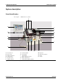
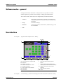
Visual identification
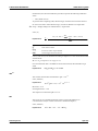
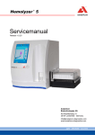
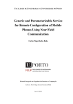
For example:
cobas b 221<6> system
P
A
O
N
B
M
L
C
K
D
J
E
F
G
H
I
A
Screen/PC unit
G
S1 Rinse Solution
M Input unit
B
Reverse side
H
S2 Fluid Pack
N
Measuring chambers
C
Docking mechanism
I
S3 Fluid Pack
O
Printer
D
AutoQC drawer
J
Bottle compartement cover
P
Pumps
E
Barcode scanner
K
Bottle compartement
F
W Waste container
L
COOX module (tHb/SO2 module)
Figure A-3
Roche Diagnostics
A-18
cobas b 221<6> system
April 2009
Instructions for Use · Revision 10.0
cobas b 221 system
2 General descriptions
System description
Screen/PC unit
The screen/PC unit serves as the graphical user interface.
All information (results, error messages, alarms, warnings, etc.) is displayed on the
screen. The screen consists of a color LCD that is covered with a touch-sensitive film
("touch screen").
As sharp objects can damage the touch-sensitive film, only touch the film using suitable pins and/or
with your fingers.
The screen/PC unit also contains a diskette drive.
Printer
Low-noise thermoprinter with integrated paper cutter (manually activated using the
"Cut" key) and optional winder.
The "Feed" key feeds in the paper.
With an installed winder, the "Automatic Cut" function is deactivated.
Measuring chamber
Underneath the top cover are the BG and, depending on the configuration, ISE
measuring chamber with the electrodes, the MSS measuring chamber with the MSS
cassette and the tHb/SO2 or COOX module.
The electrodes are flow-through electrodes with a visible sample channel.
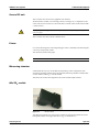
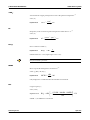
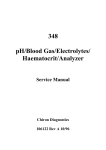
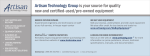
tHb/SO2 module
Figure A-4
tHb/SO2 module
The tHb/SO2 module is an optical sensor module for determining the level of total
hemoglobin (tHb) and oxygen saturation (SO2) in whole blood.
Roche Diagnostics
Instructions for Use · Revision 10.0
April 2009
A-19
2 General descriptions
cobas b 221 system
System description
COOX module
The COOX module consists of the hemolyzer and the COOX measuring chamber.
The measurement is based on the principle of spectral photometry.
Pumps
Depending on the configuration, up to three peristaltic pumps transport the sample
and the operating fluids inside the instrument.
Input unit
The sample insertion as well as the aspiration of solutions is carried out via input unit
which consists of the following:
o
o
T&D module:
o
T&D disk
o
T&D tubing set with wash-water jet
o
Plug control
o
Fill port
Sample drip tray
Bottle compartment
Behind the bottle compartment cover are the S1 Rinse Solution bottle, the
S2 Fluid Pack, the W Waste Container and, depending on the configuration,
S3 Fluid Pack (cobas b 221<5> system and cobas b 221<6> system only).
Roche Diagnostics
A-20
April 2009
Instructions for Use · Revision 10.0
cobas b 221 system
2 General descriptions
System description
Reverse side
E
A
D
B
C
A
Power supply
D
Air filter
B
Main power switch and connector
E
Interfaces
C
Warning and identification labels
Figure A-5
Reverse side
Power supply
This unit also contains the main power switch and the connector.
B
C
A
A
Power supply
B
Main power switch OFF
C
Main power switch ON
Figure A-6
Roche Diagnostics
Instructions for Use · Revision 10.0
Power supply
April 2009
A-21
2 General descriptions
cobas b 221 system
System description
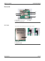
Interfaces
Only data processing units manufactured according to the standards IEC 950
(UL1950) may be attached to the interface connections!
A
B
C
D
E
F
A
Power supply
D
Ext. keyboard/barcode scanner
B
Service connector
E
RS 232
C
RS 232
F
10BaseT
Figure A-7
Interfaces (without USB)
A
B
C
D
A
Power supply
D
RS 232
B
Service connector
E
USB
C
Ext. keyboard/barcode scanner
F
10BaseT
Figure A-8
o
E
F
Interfaces (with USB)
Variant 2:
2x RS 232 interfaces (COM 1 and COM 2) (SN < 1500)
e see Figure A-7 on page A-22
o
Variant 1:
1x RS 232 interface (COM 1) and 1x USB (SN > 1500)
e see Figure A-8 on page A-22
o
1x 10BaseT Ethernet (RJ45)
o
Ext. keyboard / barcode scanner: PS/2 DIN - 6 pin female connector
o
1 service connector
o
Power (power supply is connected)
No reverse compatibility from Variant 2 to Variant 1 possible.
Roche Diagnostics
A-22
April 2009
Instructions for Use · Revision 10.0
cobas b 221 system
2 General descriptions
System description
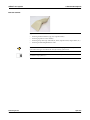
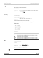
Barcode scanner
Figure A-9
Barcode scanner
o
Scanning of electrode data (type, lot, expiration date)
o
Scanning of patient or user identity
o
Scanning of QC data (QC material, lot, basis, expiration date, target values, etc.)
o
Scanning of desired alphanumeric code
Press the button on the underside to activate the scanner! A beeping sound and a brief illumination
of the LED on the upper side indicate the successful scanning of the barcode.
For more detailed information, please see enclosed manual of the PS2 hand-held scanner
(included in scope of delivery).
Roche Diagnostics
Instructions for Use · Revision 10.0
April 2009
A-23
2 General descriptions
cobas b 221 system
System description
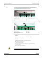
Warning and identification labels (incl. nameplate)
Figure A-10
cobas b 221<1> system, cobas b 221<3> system and cobas b 221<5> system (with tHb/SO2 module)
Figure A-11
cobas b 221<2> system, cobas b 221<4> system and cobas b 221<6> system
Roche Diagnostics
A-24
April 2009
Instructions for Use · Revision 10.0
cobas b 221 system
3 Installation and shutdown
Contents
Installation and shutdown
In this chapter, the software-guided installation and shutdown of the instrument are
described step by step. The sequence of the steps described must be strictly followed.
In this chapter
Chapter
3
Installation ..................................................................................................................... 27
Location ................................................................................................................... 27
Accessories ............................................................................................................... 28
Installation ............................................................................................................... 30
1. Screen/PC unit ............................................................................................... 30
2. Power supply .................................................................................................. 31
3. Attach power cord and barcode scanner ...................................................... 31
4. Switch on ........................................................................................................ 31
5. Installation ..................................................................................................... 32
6. Select language ............................................................................................... 32
7. Set the date and time ..................................................................................... 32
8. Cal. intervals & timing .................................................................................. 33
9. Set valves for FMS tubing exchange ............................................................. 33
10. Fix screws at V19 (bottle compartment) .................................................... 34
11. Insert right FMS tube at VM (bottle compartment) ................................. 34
12. Insert fill port and sample inlet path (glass tube) ...................................... 35
13. Insert printer paper ..................................................................................... 37
14. Insert peristaltic pump tubes ...................................................................... 39
15. Go to AutoQC service position .................................................................. 39
16. Open the AutoQC drawer and remove the AutoQC valve clamp ............. 40
17. Go to AutoQC home position .................................................................... 40
18. Open AutoQC drawer and insert ampoule holder .................................... 40
19. Open the measuring chamber cover and insert the sensors ...................... 40
20. Open bottle compartment cover and insert Waste container & packs ..... 44
21. Complete installation .................................................................................. 46
22. Perform MSS polarization (cobas b 221<5> system and
Roche Diagnostics
Instructions for Use · Revision 10.0
April 2009
A-25
3 Installation and shutdown
cobas b 221 system
Contents
cobas b 221<6> system only) ........................................................................... 46
23. Checking the barometer value .................................................................... 47
24. Quality control ............................................................................................ 47
Shutdown ....................................................................................................................... 48
Less than 24 hours ................................................................................................... 48
Longer than 24 hours .............................................................................................. 48
1. Open bottle compartment cover and only remove bottle S1 and packs
(depending on the configuration S2 and S3). .................................................. 49
2. Fill the shutdown kit with distilled water ..................................................... 49
3. Insert shutdown kit into space S2 ................................................................. 49
4. Remove shutdown kit from space S2 ............................................................ 49
5. Insert shutdown kit into space S3 (cobas b 221<5> system and
cobas b 221<6> system only) ........................................................................... 50
6. Remove shutdown kit from space S3 (cobas b 221<5> system and
cobas b 221<6> system only) ........................................................................... 50
7. Remove Waste container ............................................................................... 50
8. Open the measuring chamber cover and remove the sensors ..................... 50
9. Remove the peristaltic pump tubes .............................................................. 50
10. Remove the printer paper ........................................................................... 51
11. Open T&D ................................................................................................... 52
12. Remove fill port and sample inlet path (glass tube) .................................. 52
13. Set valves for FMS tubing exchange ........................................................... 53
14. Release screws at V19 (bottle compartment) ............................................. 53
15. Remove right FMS tube at VM (bottle compartment) ............................. 53
16. Go to AutoQC home position .................................................................... 54
17. Open the AutoQC drawer and remove the ampoule holder ..................... 54
18. Go to AutoQC service position ................................................................... 54
19. Open AutoQC drawer and insert the AutoQC valve clamp ...................... 54
20. Go to AutoQC home position .................................................................... 55
21. Complete shutdown .................................................................................... 55
Roche Diagnostics
A-26
April 2009
Instructions for Use · Revision 10.0
cobas b 221 system
3 Installation and shutdown
Installation
Installation
Location
For best results, a suitable, level location that is not subject to direct sunlight is
required for the instrument.
When installing an instrument that was stored in a cool room or was transported at
low temperatures, be aware that condensation may have formed and could cause
disturbances to the instrument. The instrument must be climatized at room
temperature for at least one hour before beginning operation.
The following conditions must be fulfilled:
o
Ambient temperature: 15 °C to 31 °C
o
Ambient air pressure: 797 - 526 mmHg (106.225 - 70.13 kPa)
From approx. 3000 m above sea level or air pressure < 526 mmHg (70.13 kPa), the specifications
for parameter PO2 are no longer fulfilled and the parameter must no longer be used for evaluation
of the clinical decisions.
After successful installation, the parameter must be permanently deactivated.
e See section 23. Checking the barometer value on page A-47
o
Avoid direct sunlight, vibration and strong electromagnetic fields (electric
motors, transformers, X-ray equipment, cellular phones...).
o
A stable and level work surface (max. 1° incline with bottles installed)
o
Relative humidity: 20 to 85%
o
At least 10 cm free space around the instrument for air circulation and electrical
connections
o
Correct voltage: 100 to 240 VAC (±10%)
After setting up the cobas b 221 system at a location that meets the necessary
conditions, the following steps must be performed to ensure the instrument is ready
for operation:
o
First check the instrument and the accessories for completeness and damage. The
completeness of the delivery can be checked through comparison with the delivery
packing slip.
If anything is missing, inform the Roche representative immediately.
If the delivery has suffered damage despite careful packing, inform the transportation
company immediately. Retain the packing material and products as evidence for the
damage claim.
Handle the instrument only at the specified holding points — risk of injury!
Take care when lifting - weight of the instrument without wash/calibrating solutions and AutoQC
is approx. 45 kg!
e See illustration on the outer packaging and in Chapter 4 Specifications, section Holding
points on page A-92!
Roche Diagnostics
Instructions for Use · Revision 10.0
April 2009
A-27
3 Installation and shutdown
cobas b 221 system
Installation
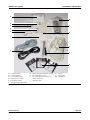
Accessories
The following parts are delivered as standard equipment with the cobas b 221 system:
o
1 barcode scanner
o
2 Power cords (US and European version)
o
1 roll printer paper
o
2 pcs fill port
o
1 sample inlet path (glass tube)
o
5 system disks
o
1 RCon (reference contact)
o
1 shutdown kit
o
1 dummy electrode
o
1 dummy MSS cassette
o
2 SCon (sensor contact)
o
1 13 mm wrench (for screen/PC unit)
1 Phillips screwdriver
o
3 pump tubes
Not shown in Figure A-12 on page A-29:
Roche Diagnostics
A-28
o
1 screen/PC unit
o
1 power supply
o
1 fill port
o
2 system disks
April 2009
Instructions for Use · Revision 10.0
cobas b 221 system
3 Installation and shutdown
Installation
A
M
B
L
C
D
E
K
F
J
G
I
H
A
1 Roll printer paper
G
2 Power cords (US and European version)
K
1 Fill port
B
1 Dummy electrode
H
System disks (total of 5 pcs.)
L
3 Pump tubes
C
1 Dummy MSS cassette
I
1 13 mm wrench (for screen/PC unit);
M 1 Shutdown kit
D
RCon (reference contact)
E
SCon (sensor contact)
F
1 Sample inlet path (glass tube)
Figure A-12
1 Phillips screwdriver
J
1 Barcode scanner
Accessories
Roche Diagnostics
Instructions for Use · Revision 10.0
April 2009
A-29
3 Installation and shutdown
cobas b 221 system
Installation
Installation
1. Screen/PC unit
Ensure that the printed serial number on the rear of the screen/PC unit is the same as the unit serial
number on the nameplate!
1 Unscrew the fixing nut from the screen.
2 Place the screen/PC unit on the swivel arm.
3 At the base of the swivel arm, place the brake packet and lock nut on the shaft and
tighten using the 13 mm wrench provided in the accessories.
A
B
C
D
A
Screen/PC unit
C
Fixing nut
B
Swivel arm
D
Brake packet
Figure A-13
Swivel arm of the Screen/PC unit
4 Connect the cable to the screen and push it into the cable routing bar.
Roche Diagnostics
A-30
April 2009
Instructions for Use · Revision 10.0
cobas b 221 system
3 Installation and shutdown
Installation
2. Power supply
1 Place the power supply, including the two adapter connectors, on the holder and
position them.
A
B
B
A
Screw
Figure A-14
B
Holder
Power supply
2 Tighten the screw.
3. Attach power cord and barcode scanner
1 Connect the power cord.
2 Connect the barcode scanner, and, if necessary, the network connection to the
appropriate port on the rear side of the cobas b 221 system.
4. Switch on
o
Roche Diagnostics
Instructions for Use · Revision 10.0
Switch the instrument on and wait until the program has completely loaded and
started. Before starting the installation, you must set the language, in which the
unit is to be operated, the date and the time.
April 2009
A-31
3 Installation and shutdown
cobas b 221 system
Installation
5. Installation
When carrying out the installation, follow the on-screen instructions.
Installation must be carried out completely and may not be interrupted.
Observe the listed sequence while performing the actions.
If the automatic first installation is unsuccessful, you must carry out the installation process
manually. To do this, press the following buttons:
[System] > [Utilities] > [Installation]
Processing the actions
Manual
The corresponding line of the list box contains an instruction which must be
performed manually. Then press [Confirm action].
Automatic
If there is an automatic sequence for any action, you can start this by clicking
[Start process].
If an action has been completed successfully (manually or automatically),
this symbol is displayed.
6. Select language
1 Press the following buttons:
h Setup > Instrument > Language
If the current language is "English": [Instrument] > [Language]
2 Select the language.
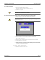
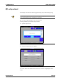
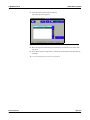
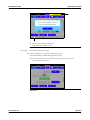
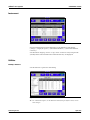
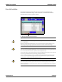
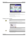
7. Set the date and time
o
Press the following buttons:
h Setup > Times & Intervals > Act. time / date
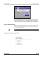
Figure A-15
Roche Diagnostics
A-32
Act. time / date
April 2009
Instructions for Use · Revision 10.0
cobas b 221 system
3 Installation and shutdown
Installation
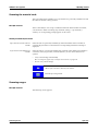
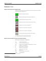
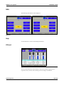
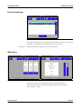
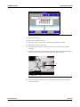
8. Cal. intervals & timing
o
Press the following button:
h Setup > Times & intervals > Cal. intervals & timing
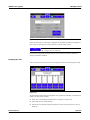
Figure A-16
Cal. intervals
Use this function to enter the automatic calibration times and intervals for system,
1 point and 2 point calibrations.
The time scale uses markers to show the selected interval for the 2P calibration
and the start time for the system calibration.
Intervals:
System calibration
Every 8, 12 or 24 hours.
Enter the [Start time] of a system calibration to which all calibrations are oriented.
2P calibration
Every 4, 8 or 12 hours.
1P calibration
All 30 or 60 minutes (USA: only every 30 minutes).
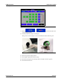
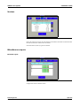
9. Set valves for FMS(a) tubing exchange
o
Press [Start process]. This action is performed automatically.
Valve V19 is pushed in to prevent the tube from being pinched while the aluminum part is
tightened! Valve VM is pushed out.
(a) "Fluid Mixing System" - Mixing of calibration solution A and B in a certain ratio
Roche Diagnostics
Instructions for Use · Revision 10.0
April 2009
A-33
3 Installation and shutdown
cobas b 221 system
Installation
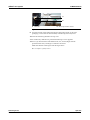
10. Fix screws at V19 (bottle compartment)
1 Open the bottle compartment cover and the docking mechanism "S3".
2 Tighten the screws on valve V19 (approx. 2-3 rotations).
e see Figure A-17!
Use the delivered screwdriver!
A
A
A
Screws on valve V19
Figure A-17
Valve V19 and VM
3 To return to the installation window, close the docking mechanism and the bottle
compartment cover.
11. Insert right FMS tube at VM (bottle compartment)
1 Open the bottle compartment cover and the docking mechanism "S3".
2 Slide the tube under the tube clip of valve VM.
A
A
VM
Figure A-18
B
B
V19
Valve VM
3 Close docking mechanism and bottle compartment cover.
Roche Diagnostics
A-34
April 2009
Instructions for Use · Revision 10.0
cobas b 221 system
3 Installation and shutdown
Installation
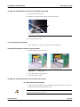
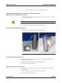
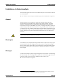
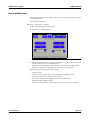
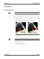
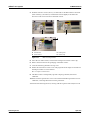
12. Insert fill port and sample inlet path (glass tube)
1 Pull out the sample drip tray.
2 Remove the T&D cover and the unit cover.
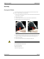
3 Insert the fill port started from the 6 o’clock position as shown below.
4 Push the fill port straight onto the insert needle.
Do not bend the insert needle during this process!
A
A
Needle
Figure A-19
Insert needle
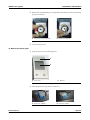
5 Rotate the fill port 90° clockwise and upwards until it snaps into place.
Figure A-20
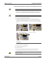
6 Open the T&D lock.
e see Figure A-21 on page A-36, A
7 Insert the glass tube into the guides, fasten it and check it for a correct position.
e see Figure A-21 on page A-36, C
e see Figure A-21 on page A-36, D
Roche Diagnostics
Instructions for Use · Revision 10.0
April 2009
A-35
3 Installation and shutdown
cobas b 221 system
Installation
A
B
C
C
D
A
T&D lock
C
Insert the glass tube into the guides
B
Glass tube
D
Fasten and check for correct position
Figure A-21
Glass tube
8 Close the T&D lock again. Check the correct positioning of the sample inlet path
to the bypass nipple (see below)!
A
A
Bypass nipple
Figure A-22
T&D lock
9 Close the T&D cover.
10 Insert the sample drip tray.
Roche Diagnostics
A-36
April 2009
Instructions for Use · Revision 10.0
cobas b 221 system
3 Installation and shutdown
Installation
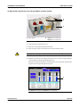
13. Insert printer paper
The printer paper is heat sensitive on one side only. Observe the correct insertion of the thermal
paper roll.
A
B
A
Printer cover
Figure A-23
B
Paper lid
Printer
1 Open the printer cover and the paper lid.
2 Cut the start of the paper so that it is straight.
3 Place the paper roll into the holder.
4 Make sure that the printer lever is in the "down" position (see below).
A
A
Printer lever "down" position
Figure A-24
Roche Diagnostics
Instructions for Use · Revision 10.0
Printer lever
April 2009
A-37
3 Installation and shutdown
cobas b 221 system
Installation
5 Insert the beginning of the paper according to the instructions on the inside of the
paper lid (see below).
A
B
A
Paper lid
B
Printer lever
Figure A-25
Insert printer paper - without take-up unit
Figure A-26
Insert printer paper - with take-up unit (optional)
6 The paper is automatically pulled into the printer.
7 Close paper lid.
With take-up unit (optional)
1 Press the paper feed button until the paper is long enough.
2 Insert the beginning of the paper in the take-up unit according to the instructions
on the inside of the paper lid.
e see Figure A-26 on page A-38
Press the take-up unit (rods) fully onto the holder and rotate until the paper is taut on the rods and
paper lid, so that the entire roll of paper can be taken up. During operation, the paper should be
tautened now and then by turning the take-up roller.
3 Close printer cover.
With an installed take-up unit, the "Automatic Cut" function is deactivated.
Roche Diagnostics
A-38
April 2009
Instructions for Use · Revision 10.0
cobas b 221 system
3 Installation and shutdown
Installation
14. Insert peristaltic pump tubes
1 Open the peristaltic pump's clear plastic cover (tension lever).
2 Push the linear bracket (white plastic part) upwards (see below).
A
B
C
A
Tension lever
B
Pump head
C
Linear bracket
Figure A-27
Peristaltic pump
3 Place the tubing set around the corresponding rolling wheel (see below/A). Check
that the tubing set is correctly orientated (the grip end must be pointing upwards,
see below/B).
4 Close the clear plastic cover (tension lever). The tubing holder is then pressed into
the sealer (see below/B).
A
Place the tubing set
Figure A-28
B
Close the tension lever
Peristaltic pump
AutoQC module (option)
The installation with an AutoQC module (optional) must be performed by a Roche Diagnostics
Service Representative!
15. Go to AutoQC service position
o
Roche Diagnostics
Instructions for Use · Revision 10.0
Press [Start process]. This action is performed automatically.
April 2009
A-39
3 Installation and shutdown
cobas b 221 system
Installation
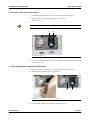
16. Open the AutoQC drawer and remove the AutoQC valve clamp
1 Pull out the AutoQC drawer.
2 Pull the key of the AutoQC valve up and out (see below).
A
A
AutoQC valve clamp
Figure A-29
AutoQC valve clamp
3 Close the AutoQC drawer.
17. Go to AutoQC home position
o
Press [Start process]. This action is performed automatically.
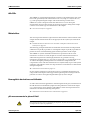
18. Open AutoQC drawer and insert ampoule holder
1 Pull the AutoQC drawer out again.
A
without ampoule holder
Figure A-30
B
with ampoule holder
AutoQC drawer
2 Insert the AutoQC ampoule holder.
3 Close the AutoQC drawer.
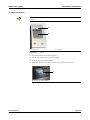
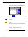
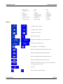
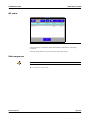
19. Open the measuring chamber cover and insert the sensors
a BG / ISE measuring chamber
1 Open the measuring chamber cover (push the right edge of the MC cover to the
left with a finger and open up the MC cover).
In each case, open only the relevant measuring chamber.
Keep the bottle compartment cover closed.
Roche Diagnostics
A-40
April 2009
Instructions for Use · Revision 10.0
cobas b 221 system
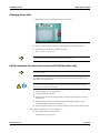
3 Installation and shutdown
Installation
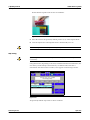
The following screen appears:
Figure A-31
Changing of electrodes
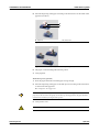
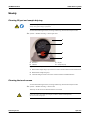
2 Open the locking lever.
e see Figure A-34 on page A-42
3 Follow the instructions on the screen.
Check the internal electrolyte of the electrodes for possible air bubbles (see below).
If there are air bubbles between the contact pin and the membrane, there will not be effective
electrical conduction. Result: calibration and measurement errors!
4 Remove any air bubbles.
Remove air bubbles by holding the electrode vertically and by tapping lightly with
a fingernail against the electrode body (see below).
A
A
Free of air bubbles!
Figure A-32
Electrode
5 Insert the electrodes, beginning at the right and proceeding left according to the
color code.
6 Push all electrodes slightly to the right so that they are lined up together without
gaps.
Roche Diagnostics
Instructions for Use · Revision 10.0
April 2009
A-41
3 Installation and shutdown
cobas b 221 system
Installation
a Insertion of the reference electrode
1 Insert the reference electrode.
Figure A-33
Reference electrode
2 Insert the reference tube into the upper tube guide channel of the left locking lever
and into the tube holder of the cover hinge. Close the locking lever (see below).
A
A
Locking lever
Figure A-34
Insertion of the reference electrode
3 Connect the white connector on the end of the tube to the measuring chamber
cassette (see below).
A
B
A
Connector
Figure A-35
B
Measuring chamber cassette
Insertion of the reference electrode 2
4 Scan the barcodes located on the inner packaging of each electrode or enter the
barcodes manually with the help of the keyboard.
5 Close the measuring chamber cover.
Roche Diagnostics
A-42
April 2009
Instructions for Use · Revision 10.0
cobas b 221 system
3 Installation and shutdown
Installation
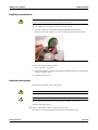
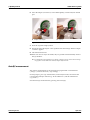
a MSS measuring chamber (for instrument versions with MSS module only)
Hold the MSS cassette only at the designated handle and avoid touching the contacts.
1 Open the cover of the MSS measuring chamber (apply force to the right edge of
the MC cover with a finger to push it to the left and open up the MC cover).
Keep the bottle compartment cover closed!
2 Open the contact clip and the locking lever.
3 Depending on the MSS parameter configuration, insert the MSS reference
electrode (Ref + dummy) (see Figure A-36/A) or the reference contact (RCon)
(see Figure A-36/B) and the MSS cassette, close the contact clip and the locking
lever.
A
A
B
Ref + dummy (for Glu/Lac/Urea)
B
RCon (Glu or Glu/Lac)
D
C
C
Locking lever
D
Contact clip
Figure A-36
MSS measuring chamber
4 Read in the barcode of the packaging.
5 Close the measuring chamber cover.
6 Close the top cover.
7 Prepare a syringe or capillary with whole blood for polarization. Having
completed the installation process, the unit requests a blood sample.
The blood should have a volume of at least 150 μL, contain heparin as an anticoagulant, and be
stored for less than 24 hours.
Roche Diagnostics
Instructions for Use · Revision 10.0
April 2009
A-43
3 Installation and shutdown
cobas b 221 system
Installation
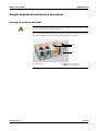
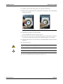
20. Open bottle compartment cover and insert Waste container & packs
A
A
B
A
Ruber sealings
B
cobas b 221<5> system and
cobas b 221<6> system only
Figure A-37
Waste container & packs
1 Open the bottle compartment cover.
2 Open the corresponding docking mechanism.
3 Insert an empty waste water bottle and a S1 Rinse Solution bottle.
Remove packs’ rubber sealings.
4 Push the two packs into the appropriate location in accordance with the labeling
on the docking mechanisms until the packs lock.
Using the transponder attached to the bottle/packs, the instrument automatically
recognizes the corresponding bottle or packs.
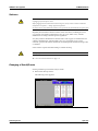
A
A
cobas b 221<5> system and cobas b 221<6> system only
Figure A-38
Roche Diagnostics
A-44
Changing of bottles and packs
April 2009
Instructions for Use · Revision 10.0
cobas b 221 system
3 Installation and shutdown
Installation
A
A
cobas b 221<5> system and cobas b 221<6> system only
Figure A-39
Bottle compartment
5 Close the docking mechanism and the bottle compartment cover.
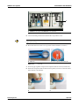
To avoid splashing the S1 Rinse Solution, deaerate the bottle at about 3000 m above sea level or
higher before inserting it.
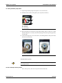
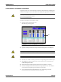
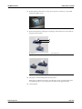
6 Place the bottle tool on the screw cap of the S1 Rinse Solution (see below).
A
Bottle tool
Figure A-40
B
Screw cap with placed bottle tool
Screw cap
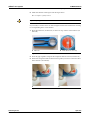
7 Press the grips together and press the transparent disk downward (see below/A).
8 Rotate the transparent disk clockwise and stop when you notice a resistance after a
short distance (see below/B).
A
Figure A-41
Roche Diagnostics
Instructions for Use · Revision 10.0
B
Open bottle
April 2009
A-45
3 Installation and shutdown
cobas b 221 system
Installation
21. Complete installation
1 Press the [Complete installation] button.
Automatic sequences take place and the unit warms up.
2 Installation is complete.
If a power failure occurs during installation, the installation starts anew with the next restart.
Actions which were performed successfully are discarded.
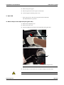
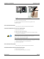
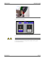
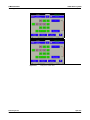
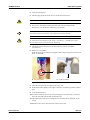
22. Perform MSS polarization (cobas b 221<5> system and cobas b 221<6> system only)
1 Prepare a syringe or capillary with whole blood for polarization.
The blood should have a volume of at least 150 μL, contain heparin as an anticoagulant, and be
stored for less than 24 hours.
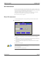
Figure A-42
MSS polarization
2 The blood sample is inserted via fill port similar to a measurement.
e see Chapter 6 Measurement
3 The MSS cassette is subsequently exposed to liquid, polarized and heated.
4 A system calibration is carried out.
5 If, after inserting the cassette, the automatic polarization was not successful and
the MSS sensors are not calibrated, you must manually polarize the MSS cassette.
To do this, press the following buttons:
h System > Utilities > MSS polarization
6 Follow the instructions on the screen!
Roche Diagnostics
A-46
April 2009
Instructions for Use · Revision 10.0
cobas b 221 system
3 Installation and shutdown
Installation
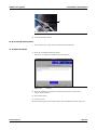
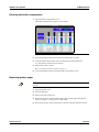
23. Checking the barometer value
h System > Component test > Control sensors > Baro sensor
1 If the barometer value deviates by more than ± 4 mbar from the value indicated by
a precision barometer, it will be necessary for Technical support to calibrate the
barometer!
A wrong barometer value leads to wrong PO2 measurement results.
Important:
From approx. 3000 m above sea level or air pressure < 526 mmHg (70.13 kPa), the specifications
for parameter PO2 are no longer fulfilled and the parameter must no longer be used for evaluation
of the clinical decisions. The parameter PO2 must be permanentely deactivated.
2 To deactivate the parameter PO2 press the following buttons:
h Setup > Parameter > Miscellaneous settings > Activated / deactivated for calibrations
24. Quality control
1 Define the material and if an AutoQC drawer (option) is available insert the mats
before performing a quality control measurement.
e For details, see Chapter 7 Quality control
2 Perform quality control tests for all 3 levels (low, normal, high). Make sure that
the results agree with the target values.
e See Chapter 7 Quality control
Roche Diagnostics
Instructions for Use · Revision 10.0
April 2009
A-47
3 Installation and shutdown
cobas b 221 system
Shutdown
Shutdown
Less than 24 hours
If the cobas b 221 system is not used for a short period of time only (< 24 hours), then
activate the following function, starting with the top level of the analyzer mode:
h System > Utilities > Shutdown PC
This function allows for switching off the touch screen/PC unit and is completed with
manually switching off the instrument.
Follow the instructions on the screen!
MSS sensors (Glu / Lac / Urea/BUN) are destroyed during this operation.
If the instrument is turned on again, a new MSS cassette must be inserted.
e See section 19. Open the measuring chamber cover and insert the sensors on page A-40.
Longer than 24 hours
If the cobas b 221 system will be shut down for longer than 24 hours, perform the
following procedure.
Before performing a shutdown, Roche Diagnostics recommends decontaminating all surfaces and
tube paths.
e see Chapter 10 Maintenance, Abschnitt Decontamination on page C-5!
Activate the following function, starting with the top level of the analyzer mode:
h System > Utilities > Put out of operation
All solutions and electrodes have to be removed during the shutdown procedure.
The procedure ends in switching off the instrument.
Follow the instructions on the screen.
Observe the listed sequence while performing the actions.
Processing the actions:
Manual:
Automatic:
Roche Diagnostics
A-48
The corresponding line of the list box contains an instruction which must be
performed manually. Then press [Confirm action].
If there is an automatic sequence for any action, you can start this by clicking [Start
process].
April 2009
Instructions for Use · Revision 10.0
cobas b 221 system
3 Installation and shutdown
Shutdown
Upon successful completion, this symbol is displayed.
1. Open bottle compartment cover and only remove bottle S1 and packs
(depending on the configuration S2 and S3).
1 Open bottle compartment cover and docking mechanism and remove bottle S1
and the packs (S2 and S3).
Do not remove the waste container!
2 Close docking mechanism and bottle compartment cover.
2. Fill the shutdown kit with distilled water
o
Fill the shutdown kit about halfway with distilled water.
Figure A-43
Shutdown kit
3. Insert shutdown kit into space S2
1 Open bottle compartment cover and docking mechanism S2 and insert the
shutdown kit into space S2.
2 Close docking mechanism and bottle compartment cover.
3 Perform "Washing of the tubes".
4. Remove shutdown kit from space S2
1 Open bottle compartment cover and docking mechanism S2 and remove the
shutdown kit.
2 Close docking mechanism and bottle compartment cover.
3 Perform "Emptying of the tubes".
Roche Diagnostics
Instructions for Use · Revision 10.0
April 2009
A-49
3 Installation and shutdown
cobas b 221 system
Shutdown
5. Insert shutdown kit into space S3 (cobas b 221<5> system and cobas b 221<6> system only)
1 Open bottle compartment cover and docking mechanism S3 and insert the
shutdown kit into space S3.
2 Close docking mechanism and bottle compartment cover.
3 Perform "Washing of the tubes".
6. Remove shutdown kit from space S3 (cobas b 221<5> system and cobas b 221<6> system only)
1 Open bottle compartment cover and docking mechanism S3 and remove the
shutdown kit.
2 Close docking mechanism and bottle compartment cover.
3 Perform "Emptying of the tubes".
7. Remove Waste container
1 Open bottle compartment cover and docking mechanism W.
2 Remove the waste water container (W Waste Container).
3 Close docking mechanism and bottle compartment cover.
8. Open the measuring chamber cover and remove the sensors
1 Remove the top cover and open all measuring chamber covers.
2 Open the measuring chamber cover (push the right edge of the MC cover to the
left with a finger and open up the MC cover).
3 Open the locking levers and the contact clip (MSS measuring chamber).
4 Sequentially remove the electrodes and the MSS cassette from the measuring
chambers.
5 Close the locking lever, the contact clip and all the measuring chamber covers.
9. Remove the peristaltic pump tubes
1 Open the peristaltic pump's clear plastic cover (tension lever) (see below).
A
B
C
A
Tension lever
B
Pump head
C
Linear bracket
Figure A-44
Peristaltic pump
2 Push the linear bracket (white plastic part) upwards (see below/A).
Roche Diagnostics
A-50
April 2009
Instructions for Use · Revision 10.0
cobas b 221 system
3 Installation and shutdown
Shutdown
3 Remove the complete tubing set (tubing holder and tubing) of the corresponding
pump (see below/B)
A
Push the linear bracket upwards
Figure A-45
B
Remove the tubing set
Peristaltic pump
4 Close the tension lever.
10. Remove the printer paper
1 Open the printer cover and the paper lid.
A
B
A
Printer cover
Figure A-46
B
Paper lid
Printer cover / paper lid
2 Move the printer lever upwards (see below/A).
A
Printer lever "upwards"
Figure A-47
Roche Diagnostics
Instructions for Use · Revision 10.0
B
Printer lever "down"
Printer lever
April 2009
A-51
3 Installation and shutdown
cobas b 221 system
Shutdown
3 Remove the printer paper.
4 Move the printer lever down again (see above/B).
5 Close the paper lid and the printer cover.
11. Open T&D
o
Press [Start process]. This action is performed automatically.
The T&D disk turns to position 1.
12. Remove fill port and sample inlet path (glass tube)
1 Remove the sample drip tray.
2 Remove the T&D cover.
3 Open the T&D lock and remove the sample inlet path (glass tube).
A
B
A
T&D lock
B
Figure A-48
T&D lock & sample inlet path
Sample inlet path (glass tube)
4 Turn the fill port downward by 90° and pull it straight off of the needle.
Do not bend the needle!
Roche Diagnostics
A-52
April 2009
Instructions for Use · Revision 10.0
cobas b 221 system
3 Installation and shutdown
Shutdown
B
A
A
Fill port
Figure A-49
B
Needle
Fill port
5 Close the T&D lock again.
6 Close the T&D cover.
13. Set valves for FMS tubing exchange
o
Press [Start process]. This action is performed automatically.
Both valves are pushed out.
14. Release screws at V19 (bottle compartment)
1 Open the bottle compartment cover and the docking mechanism S3.
2 Loosen the screws (A) of the aluminum part of valve V19 (approx. 2-3 turns).
A
A
V 19
A
Screws
Figure A-50
Valve V19
3 Close the docking mechanism S3 and the bottle compartment cover.
15. Remove right FMS tube at VM (bottle compartment)
1 Open the bottle compartment cover and the docking mechanism S3.
2 Slide the tube out under the tube clip of valve VM.
Roche Diagnostics
Instructions for Use · Revision 10.0
April 2009
A-53
3 Installation and shutdown
cobas b 221 system
Shutdown
B
A
A
VM
Figure A-51
B
Tube clip
Valve VM
3 Pressure is removed from the tubes.
4 Close the docking mechanism and the bottle compartment cover.
If available (option):
16. Go to AutoQC home position
o
Press [Start process]. This action is performed automatically.
17. Open the AutoQC drawer and remove the ampoule holder
1 Pull out the AutoQC drawer.
2 Remove the AutoQC ampoule holder.
3 Remove the already opened ampoules from the mats and dispose of them
according to the local guidelines.
If individual ampoules remain in the white ampoule holder after removing the mats, note that
these open ampoules may break on removal with the attendant risk of injury.
Before inserting a new mat remove them all carefully!
Always wear gloves! CAUTION: Danger of spilling!
4 Leave the full ampoules in the mats and store them in a refrigerator in accordance
with their storage temperature (see packaging insert).
5 Close the AutoQC drawer.
18. Go to AutoQC service position
o
Press [Start process]. This action is performed automatically.
19. Open AutoQC drawer and insert the AutoQC valve clamp
1 Pull out the AutoQC drawer.
2 Insert the clamp of the AutoQC valve (see below).
Roche Diagnostics
A-54
April 2009
Instructions for Use · Revision 10.0
cobas b 221 system
3 Installation and shutdown
Shutdown
A
A
AutoQC valve clamp
Figure A-52
AutoQC valve clamp
3 Close the AutoQC drawer.
20. Go to AutoQC home position
o
Press [Start process]. This action is performed automatically.
21. Complete shutdown
1 Press the [Complete shutdown] button.
Shut down is complete. The following screen appears:
Figure A-53
Shutdown
2 Press the [Shutdown PC] button. Follow the instructions on the screen.
The PC is booted down.
3 Turn off the device.
4 Close top cover.
Remove the transport, power cable, scanner and, if available, network connectors.
Roche Diagnostics
Instructions for Use · Revision 10.0
April 2009
A-55
3 Installation and shutdown
cobas b 221 system
Shutdown
Roche Diagnostics
A-56
April 2009
Instructions for Use · Revision 10.0
cobas b 221 system
4 Specifications
Contents
Specifications
In this chapter, the performance data, as well as product and environmental data are
described.
In this chapter
Chapter
4
Performance data .......................................................................................................... 59
Measurement parameters ........................................................................................ 59
Reproducibility ........................................................................................................ 60
Linearity ................................................................................................................... 70
Correlation to other methods ................................................................................. 82
Sample throughput ....................................................................................................... 86
Measurement times of the samples .............................................................................. 86
Sample volumes ............................................................................................................. 87
Sample types .................................................................................................................. 87
Calibrations ................................................................................................................... 88
Environmental parameters ........................................................................................... 89
Temperature / humidity / stability ......................................................................... 89
Product data .................................................................................................................. 91
Electrical data .......................................................................................................... 91
Classification ............................................................................................................ 91
Dimensions .............................................................................................................. 91
Weight ...................................................................................................................... 91
Acoustic Noise Level ................................................................................................ 91
Holding points ......................................................................................................... 92
AutoQC .......................................................................................................................... 92
Printer ............................................................................................................................ 92
Touch screen-PC unit .................................................................................................... 93
Barcode Scanner ............................................................................................................ 93
Roche Diagnostics
Instructions for Use · Revision 10.0
April 2009
A-57
4 Specifications
cobas b 221 system
Contents
Roche Diagnostics
A-58
April 2009
Instructions for Use · Revision 10.0
cobas b 221 system
4 Specifications
Performance data
Performance data
Measurement parameters
Parameter
specified for
PO2
B/Q
0 - 800 mmHg
PCO2
B/Q
4 – 200 mmHg
pH
B/Q/S/PF
6.0 - 8.0
Sodium
B/Q/S/A/D
20 - 250 mmol/L
Potassium
B/Q/S/A/D
0.2 - 20 mmol/L
Chloride
B/Q/S
20 - 250 mmol/L
ionized Calcium
B/Q/S/A/D
0.1 - 4.0 mmol/L
Hct
B/Q
10 – 80 %
Glucose
cobas b 221<6> system only)
B/Q/S
0.5 – 40 mmol/L
9.01 - 720.8 mg/dL
Lactate (cobas b 221<5> system,
cobas b 221<6> system only)
B/Q/S
0.2 – 20 mmol/L
1.8016 - 180.16 mg/dL
Urea (cobas b 221<6> system only)
B/Q/S
0.5 – 30 mmol/L
3.0028 - 180.168 mg/dL
tHb module
B/Q
3 – 25 g/dL
1.8606 - 15.505 mmol/L
SO2 module
B/Q
50 – 100 %
tHb (COOX)
B/Q
3 – 25 g/dL
SO2 (COOX)
B/Q
0 – 100 %
HHb (COOX)
B/Q
0 – 100 %
COHb (COOX)
B/Q
0 – 100 %
O2Hb (COOX)
B/Q
0 – 100 %
MetHb (COOX)
B/Q
0 – 100 %
Bilirubin (neonatal) (COOX)
B/Q
3 - 50 mg/dL
(a) (cobas b 221<5> system,
Baro
Table A-1
specified range
0.4008 - 16.032 mg/dL
51.3 - 855 μmol/L
450 - 800 mmHg
Measurement parameters
(a) Due to the current specifications, clinically significant deviations in the range < 3mmol/L can occur compared to other glucose measuring systems.
Especially in the neonatal field, we therefore recommend carrying out a comparative blood measurement relative to a known reference system or to
adapt the correlation table (refer to the Reference Manual, chapter "Setup" section "Correlation"). For any questions concerning this matter, contact
the local Roche organization.
B
Whole blood
Q
Aqueous QC material(a)
A
Dialysis solutions containing acetate
D
Dialysis solutions containing bicarbonate
S
Serum or plasma
PF
Pleural fluid (can be measured in serum/plasma mode)
(a) with approximate physiological ion matrix and buffer capacity
Roche Diagnostics
Instructions for Use · Revision 10.0
April 2009
A-59
4 Specifications
cobas b 221 system
Performance data
Reproducibility
"Within-Run (Swr)" and "Total Precision (ST)" was determined from 2 runs per day
with 2 replicates per run for 20 days on four cobas b 221 systems.
The mean value is the measured value of the corresponding parameter for which Swr
and ST are representative resp. have been determined.
Parameter
Unit
pH
pH units
PCO2
mmHg
PO2
mmHg
Sodium
mmol/L
Potassium
mmol/L
Chloride
mmol/L
ionized Calcium
mmol/L
Hct
%
Lactate (cobas b 221<5> system,
cobas b 221<6> system only)
mmol/L
Glucose (cobas b 221<5> system,
cobas b 221<6> system only)
mmol/L
Urea (cobas b 221<6> system only)
mmol/L
tHb (tHb module)
g/dL
SO2 (tHb module)
%
tHb (COOX)
g/dL
SO2 (COOX)
%
O2Hb
%
COHb
%
MetHb
%
HHb
%
Bilirubin (neonatal)
mg/dL
Table A-2
Units of the parameters
Material: acetat - standard solution (Level 1), NIST Traceable, n=80
Parameter
Mean
Swr
(CV%)
ST
(CV %)
Sodium
140.0
0.5600
0.40
0.7405
0.53
Potassium
2.02
0.0165
0.82
0.0290
1.44
Chloride
-
-
-
-
-
ionized Calcium
1.622
0.0155
0.96
0.0205
1.26
Table A-3
Roche Diagnostics
A-60
Acetat - standard solution (Level 1), NIST Traceable, n=80
April 2009
Instructions for Use · Revision 10.0
cobas b 221 system
4 Specifications
Performance data
Material: acetat - standard solution (Level 2), NIST Traceable, n=80
Parameter
Mean
Swr
(CV%)
ST
(CV %)
Sodium
140.1
0.5107
0.36
0.7747
0.55
Potassium
4.00
0.0171
0.43
0.0273
0.68
Chloride
-
-
-
-
-
ionized Calcium
1.166
0.0077
0.66
0.0141
1.21
Table A-4
Acetat - standard solution (Level 2), NIST Traceable, n=80
Material: tonometered human whole blood, 20 different probands, n=80
Parameter
Mean
Swr
(CV%)
ST
(CV %)
pH
7.441
0.0042
0.06
-
-
PCO2
18.3
0.3331
1.82
0.6262
3.42
PO2
137.9
0.9371
0.68
2.3258
1.69
Sodium
139.5
0.4878
0.35
-
-
Potassium
4.58
0.0260
0.57
-
-
Chloride
108.4
0.4310
0.40
-
-
ionized Calcium
1.181
0.0079
0.67
-
-
Hct
43.3
0.3203
0.74
-
-
Lactate
11.5
0.1769
1.54
-
-
Glucose
1.8
0.0648
3.51
-
-
Urea
4.8
0.0529
1.11
-
-
tHb (tHb module)
15.4
0.1461
0.95
-
-
SO2 (tHb module)
96.6
0.3744
0.39
-
-
tHb (COOX)
14.1
0.0773
0.55
-
-
SO2 (COOX)
99.9
0.0613
0.06
-
-
O2Hb
97.9
0.0684
0.07
-
-
COHb
1.4
0.0377
2.79
-
-
MetHb
0.7
0.0287
4.10
-
-
HHb
0.1
0.0601
-
-
-
Table A-5
Tonometered human whole blood, 20 different probands, n=80
Roche Diagnostics
Instructions for Use · Revision 10.0
April 2009
A-61
4 Specifications
cobas b 221 system
Performance data
Material: tonometered human whole blood, 20 different probands, n=80
Parameter
Mean
Swr
(CV%)
ST
(CV %)
pH
7.129
0.0049
0.07
-
-
PCO2
79.5
1.2629
1.59
1.9644
2.47
PO2
40.1
0.3297
0.82
0.5976
1.49
Sodium
142.3
0.7126
0.50
-
-
Potassium
4.32
0.0392
0.91
-
-
Chloride
105.2
0.5184
0.49
-
-
ionized Calcium
1.301
0.0136
1.05
-
-
Hct
40.4
0.2795
0.69
-
-
Lactate
8.7
0.2021
2.33
-
-
Glucose
2.3
0.0977
4.31
-
-
Urea
4.9
0.0583
1.18
-
-
tHb (tHb module)
15.9
0.1315
0.83
-
-
SO2 (tHb module)
55.0
0.8839
1.61
-
-
tHb (COOX)
14.1
0.1691
1.20
-
-
SO2 (COOX)
67.8
0.2479
0.37
-
-
O2Hb
66.9
0.3437
0.51
-
-
COHb
1.6
0.0549
3.53
-
-
MetHb
0.4
0.0504
12.14
-
-
HHb
31.5
0.3121
0.99
-
-
Table A-6
Tonometered human whole blood, 20 different probands, n=80
Material: human plasma, n=80
Parameter
Mean
Swr
(CV%)
ST
(CV %)
pH
7.670
0.0097
0.13
0.0549
0.72
PCO2
-
-
-
-
-
PO2
-
-
-
-
-
Sodium
140.9
0.7783
0.55
0.9920
0.70
Potassium
3.99
0.0514
1.29
0.0603
1.51
Chloride
106.0
0.4967
0.47
0.7877
0.74
ionized Calcium
1.155
0.0174
1.51
0.0339
2.94
Hct
-
-
-
-
-
Lactate
2.3
0.0349
1.52
0.1150
5.00
Glucose
5.7
0.0818
1.44
0.1695
2.97
Urea
4.8
0.0873
1.81
0.1005
2.08
Table A-7
Roche Diagnostics
A-62
Human plasma, n=80
April 2009
Instructions for Use · Revision 10.0
cobas b 221 system
4 Specifications
Performance data
Material: serum, n=80
Parameter
Mean
Swr
(CV%)
ST
(CV %)
pH
7.731
0.0120
0.15
0.0334
0.43
PCO2
-
-
-
-
-
PO2
-
-
-
-
-
Sodium
140.2
0.3226
0.23
0.6567
0.47
Potassium
4.18
0.0149
0.36
0.0330
0.79
Chloride
105.2
0.4310
0.41
0.6871
0.65
ionized Calcium
1.098
0.0092
0.84
0.0323
2.94
Hct
-
-
-
-
-
Lactate
2.3
0.0353
1.53
0.0989
4.30
Glucose
5.1
0.0737
1.45
0.1834
3.62
Urea
5.2
0.0451
0.86
0.1197
2.29
Parameter
Mean
Swr
(CV%)
ST
(CV %)
Sodium
137.9
0.7201
0.52
1.0185
0.74
Potassium
2.00
0.0224
1.12
0.0301
1.51
Chloride
-
-
-
-
-
ionized Calcium
1.605
0.0091
0.57
0.0167
1.04
Table A-8
Serum, n=80
Material: bicarbonate, n=80
Table A-9
Bicarbonate, n=80
Roche Diagnostics
Instructions for Use · Revision 10.0
April 2009
A-63
4 Specifications
cobas b 221 system
Performance data
Material: AUTOTROL PLUS B Level 1, n=40
Parameter
Mean
Swr
(CV%)
ST
(CV %)
pH
7.182
0.0039
0.05
0.0060
0.08
PCO2
65.8
0.8109
1.23
1.7861
2.72
PO2
55.4
3.6232
6.53
4.5447
8.20
Sodium
121.2
0.6188
0.51
1.1226
0.93
Potassium
2.97
0.0161
0.54
0.0283
0.95
Chloride
84.2
0.4971
0.59
1.6465
1.96
ionized Calcium
1.557
0.0089
0.57
0.0153
0.98
Hct
51.8
0.9534
1.84
1.1250
2.17
Lactate
9.2
0.0821
0.89
0.4539
4.92
Glucose
5.4
0.0612
1.12
0.1299
2.38
Urea
23.5
0.3307
1.41
0.6664
2.84
tHb (tHb module)
-
-
-
-
-
SO2 (tHb module)
-
-
-
-
-
tHb (COOX)
7.8
0.0317
0.41
0.0599
0.77
SO2 (COOX)
72.1
0.0690
0.10
0.1941
0.27
O2Hb
46.8
0.0844
0.18
0.2383
0.51
COHb
23.0
0.0371
0.16
0.1043
0.45
MetHb
12.0
0.0180
0.15
0.0513
0.43
HHb
18.1
0.0294
0.16
0.0830
0.46
Bili
6.1
0.0287
0.47
0.0477
0.78
Table A-10
AUTOTROL PLUS B Level 1, n=40
Material: AUTOTROL PLUS B Level 2, n=40
Parameter
Mean
Swr
(CV%)
ST
(CV %)
pH
7.411
0.0031
0.04
0.0047
0.06
PCO2
41.0
0.4626
1.13
0.7116
1.74
PO2
93.2
2.9752
3.19
5.0160
5.38
Sodium
139.6
0.3827
0.27
0.7718
0.55
Potassium
4.76
0.0131
0.27
0.0250
0.53
Chloride
101.0
0.3290
0.33
0.9795
0.97
ionized Calcium
1.154
0.0064
0.55
0.0138
1.20
Hct
38.6
0.2840
0.74
0.6195
1.60
Lactate
1.9
0.0135
0.70
0.0798
4.12
Glucose
2.4
0.0197
0.81
0.1172
4.83
Urea
7.3
0.0538
0.74
0.1939
2.67
tHb (tHb module)
-
-
-
-
-
SO2 (tHb module)
-
-
-
-
-
tHb (COOX)
12.1
0.0715
0.59
0.1182
0.98
SO2 (COOX)
89.6
0.1442
0.16
0.1507
0.17
O2Hb
74.3
0.2843
0.38
0.3011
0.41
Table A-11
Roche Diagnostics
A-64
AUTOTROL PLUS B Level 2, n=40
April 2009
Instructions for Use · Revision 10.0
cobas b 221 system
4 Specifications
Performance data
Parameter
Mean
Swr
(CV%)
ST
(CV %)
COHb
11.1
0.1265
1.14
0.1306
1.18
MetHb
6.0
0.0577
0.96
0.0671
1.12
HHb
8.6
0.1001
1.17
0.1041
1.21
Bili
12.4
0.0857
0.69
0.1188
0.96
Table A-11
AUTOTROL PLUS B Level 2, n=40
Material: AUTOTROL PLUS B Level 3, n=40
Parameter
Mean
Swr
(CV%)
ST
(CV %)
pH
7.571
0.0027
0.04
0.0050
0.07
PCO2
20.3
0.3114
1.53
0.5568
2.74
PO2
144.2
5.3745
3.73
6.5040
4.51
Sodium
158.9
0.5680
0.36
0.8495
0.53
Potassium
6.97
0.0343
0.49
0.0514
0.74
Chloride
119.0
0.4810
0.40
1.0305
0.87
ionized Calcium
0.546
0.0041
0.76
0.0078
1.43
Hct
26.9
0.4193
1.56
0.4298
1.60
Lactate
0.8
0.0103
1.29
0.0562
7.02
Glucose
21.0
0.1298
0.62
0.4006
1.91
Urea
2.1
0.0202
0.94
0.0757
3.53
tHb (tHb module)
-
-
-
-
-
SO2 (tHb module)
-
-
-
-
-
tHb (COOX)
20.4
0.1940
0.95
0.2357
1.15
SO2 (COOX)
97.5
0.1396
0.14
0.1400
0.14
O2Hb
92.5
0.3581
0.39
0.3617
0.39
COHb
3.3
0.1564
4.75
0.1565
4.75
MetHb
1.9
0.0773
4.13
0.0809
4.32
HHb
2.4
0.1244
5.23
0.1249
5.25
Bili
21.6
0.1621
0.75
0.1690
0.78
Table A-12
AUTOTROL PLUS B Level 3, n=40
Material: AUTOTROL PLUS B Level 4B, n=40
Parameter
Mean
Swr
(CV%)
ST
(CV %)
pH
7.418
0.0014
0.02
0.0050
0.07
PCO2
41.3
0.2720
0.66
0.6088
1.48
PO2
96.4
5.0118
5.20
8.9120
9.24
Sodium
140.6
0.3242
0.23
0.5710
0.41
Potassium
4.77
0.0135
0.28
0.0220
0.46
Chloride
101.6
0.3679
0.36
0.9279
0.91
ionized Calcium
1.104
0.0048
0.43
0.0092
0.83
Hct
36.7
0.3883
1.06
0.5049
1.38
Lactate
5.6
0.0304
0.54
0.1607
2.85
Table A-13
AUTOTROL PLUS B Level 4B, n=40
Roche Diagnostics
Instructions for Use · Revision 10.0
April 2009
A-65
4 Specifications
cobas b 221 system
Performance data
Parameter
Mean
Swr
(CV%)
ST
(CV %)
Glucose
1.4
0.0204
1.45
0.1026
7.26
Urea
13.1
0.2512
1.91
0.7169
5.46
tHb (tHb module)
-
-
-
-
-
SO2 (tHb module)
-
-
-
-
-
tHb (COOX)
6.4
0.0265
0.41
0.1241
1.93
SO2 (COOX)
62.7
0.2002
0.32
0.2514
0.40
O2Hb
36.5
0.1973
0.54
0.2474
0.68
COHb
27.6
0.0869
0.32
0.1091
0.40
MetHb
14.2
0.0414
0.29
0.0518
0.36
HHb
21.7
0.0690
0.32
0.0866
0.40
Bili
4.2
0.0146
0.34
0.0707
1.67
Table A-13
AUTOTROL PLUS B Level 4B, n=40
Material: AUTOTROL PLUS B Level 5B, n=40
Parameter
Mean
Swr
(CV%)
ST
(CV %)
pH
7.412
0.0033
0.04
0.0061
0.08
PCO2
41.4
0.3787
0.91
0.7924
1.91
PO2
94.7
3.1077
3.28
3.2578
3.44
Sodium
139.4
0.7465
0.54
0.8404
0.60
Potassium
4.76
0.0365
0.77
0.0339
0.71
Chloride
102.1
0.7601
0.74
1.3617
1.33
ionized Calcium
1.119
0.0062
0.56
0.0103
0.92
Hct
38.0
1.4404
3.79
1.4027
3.69
Lactate
12.9
0.1628
1.26
0.5348
4.14
Glucose
25.4
0.1913
0.75
0.5098
2.00
Urea
26.4
0.4122
1.56
2.5774
9.75
tHb (tHb module)
-
-
-
-
-
SO2 (tHb module)
-
-
-
-
-
tHb (COOX)
23.0
0.2175
0.94
0.3139
1.36
SO2 (COOX)
98.1
0.1568
0.16
0.1744
0.18
O2Hb
94.2
0.4087
0.43
0.4554
0.48
COHb
2.5
0.0852
3.37
0.1053
4.16
MetHb
1.4
0.0397
2.77
0.0519
3.62
HHb
1.8
0.0675
3.83
0.0837
4.75
Bili
24.1
0.2629
1.09
0.2728
1.13
Table A-14
Roche Diagnostics
A-66
AUTOTROL PLUS B Level 5B, n=40
April 2009
Instructions for Use · Revision 10.0
cobas b 221 system
4 Specifications
Performance data
Material: AUTOTROL TS+ Level 1, n=40
Parameter
Mean
Swr
(CV%)
ST
(CV %)
pH
7.172
0.0037
0.05
0.0054
0.08
PCO2
62.3
0.8276
1.33
1.5073
2.42
PO2
50.6
4.2084
8.32
5.4278
10.74
Sodium
121.9
0.8432
0.69
1.0952
0.90
Potassium
2.98
0.0333
1.12
0.0352
1.18
Chloride
84.8
0.5243
0.62
0.9029
1.06
ionized Calcium
1.591
0.0170
1.07
0.0217
1.36
Hct
56.8
1.5547
2.74
1.5912
2.80
Lactate
9.3
0.0710
0.76
0.4680
5.01
Glucose
5.5
0.0564
1.02
0.1729
3.13
tHb (tHb module)
18.7
0.0256
0.14
0.0440
0.24
SO2 (tHb module)
100.0
0.0112
0.01
0.0112
0.01
Table A-15
AUTOTROL TS+ Level 1, n=40
Material: AUTOTROL TS+ Level 2, n=40
Parameter
Mean
Swr
(CV%)
ST
(CV %)
pH
7.406
0.0022
0.03
0.0043
0.06
PCO2
43.1
0.3800
0.88
0.5716
1.33
PO2
92.5
2.8967
3.13
3.5631
3.85
Sodium
136.9
0.5024
0.37
0.7705
0.56
Potassium
4.70
0.0303
0.64
0.0414
0.88
Chloride
99.4
0.3950
0.40
0.5617
0.56
ionized Calcium
1.146
0.0141
1.23
0.0178
1.56
Hct
41.6
0.3827
0.92
0.7501
1.80
Lactate
1.9
0.0163
0.86
0.0672
3.53
Glucose
2.5
0.0204
0.83
0.1044
4.23
tHb (tHb module)
14.3
0.0773
0.54
0.0794
0.56
SO2 (tHb module)
93.3
0.1776
0.19
0.1855
0.20
Table A-16
AUTOTROL TS+ Level 2, n=40
Material: AUTOTROL TS+ Level 3, n=40
Parameter
Mean
Swr
(CV%)
ST
(CV %)
pH
7.567
0.0023
0.03
0.0047
0.06
PCO2
22.9
0.2652
1.16
0.4763
2.08
PO2
141.8
3.4549
2.44
4.0597
2.86
Sodium
156.3
0.8170
0.52
1.0626
0.68
Potassium
7.03
0.0510
0.72
0.0628
0.89
Chloride
120.3
0.4829
0.40
0.6012
0.50
ionized Calcium
0.599
0.0100
1.67
0.0128
2.13
Table A-17
AUTOTROL TS+ Level 3, n=40
Roche Diagnostics
Instructions for Use · Revision 10.0
April 2009
A-67
4 Specifications
cobas b 221 system
Performance data
Parameter
Mean
Swr
(CV%)
ST
(CV %)
Hct
22.9
0.5431
2.37
0.5799
2.53
Lactate
0.8
0.0316
4.02
0.0446
5.68
Glucose
21.3
0.6006
2.82
0.7883
3.70
tHb (tHb module)
8.3
0.0122
0.15
0.0319
0.39
SO2 (tHb module)
93.3
0.0355
0.04
0.0450
0.05
Swr
(CV%)
ST
(CV %)
Table A-17
AUTOTROL TS+ Level 3, n=40
Material: AUTOTROL TS+ Level 4A, n=40
Parameter
Mean
pH
6.880
0.0054
0.08
0.0076
0.11
PCO2
87.5
1.3229
1.51
2.4825
2.84
PO2
22.7
3.6828
16.23
5.1660
22.77
Sodium
88.0
0.5162
0.59
0.8391
0.95
Potassium
8.94
0.0584
0.65
0.1029
1.15
Chloride
67.8
0.5941
0.88
1.3054
1.93
ionized Calcium
2.543
0.0272
1.07
0.0452
1.78
Hct
75.8
0.8202
1.08
1.0158
1.34
Lactate
-
-
-
-
-
Glucose
-
-
-
-
-
Urea
-
-
-
-
-
tHb (tHb module)
11.0
0.0206
0.19
0.0281
0.26
SO2 (tHb module)
88.2
0.0303
0.03
0.0450
0.05
Table A-18
AUTOTROL TS+ Level 4A, n=40
Material: AUTOTROL TS+ Level 5A, n=40
Parameter
Mean
Swr
(CV%)
ST
(CV %)
pH
7.730
0.0042
0.05
0.0061
0.08
PCO2
9.2
1.3769
15.03
1.4213
15.51
PO2
253.6
6.0686
2.39
8.7795
3.46
Sodium
174.5
0.8890
0.51
1.2891
0.74
Potassium
2.00
0.0250
1.25
0.0346
1.73
Chloride
130.3
0.7821
0.60
1.1922
0.91
ionized Calcium
0.403
0.0065
1.61
0.0109
2.70
Hct
22.0
0.6997
3.18
0.7713
3.50
Lactate
-
-
-
-
-
Glucose
-
-
-
-
-
Urea
-
-
-
-
-
tHb (tHb module)
15.8
0.0196
0.12
0.0316
0.20
SO2 (tHb module)
95.8
0.0469
0.05
0.0596
0.06
Table A-19
Roche Diagnostics
A-68
AUTOTROL TS+ Level 5A, n=40
April 2009
Instructions for Use · Revision 10.0
cobas b 221 system
4 Specifications
Performance data
Material: MSS Level 1, NIST Traceable, n=80
Parameter
Mean
Swr
(CV%)
ST
(CV %)
Lactate
9.4
0.0670
0.71
0.2626
2.78
Glucose
5.7
0.0337
0.60
0.1231
2.18
Urea
4.9
0.0391
0.80
0.1837
3.74
Table A-20
MSS Level 1, NIST Traceable, n=80
Material: MSS Level 2, NIST Traceable, n=80
Parameter
Mean
Swr
(CV%)
ST
(CV %)
Lactate
1.9
0.0188
0.96
0.0497
2.55
Glucose
2.6
0.0267
1.05
0.0972
3.81
Urea
14.5
0.2263
1.56
0.4100
2.83
Table A-21
MSS Level 2, NIST Traceable, n=80
Material: human whole blood incl. bilirubin Level 1, n=40
Parameter
Mean
Swr
(CV%)
ST
(CV %)
Bili
8.2
0.1202
1.47
0.6198
7.56
Table A-22
Human whole blood incl. bilirubin Level 1, n=40
Material: human whole blood incl. bilirubin Level 2, n=40
Parameter
Mean
Swr
(CV%)
ST
(CV %)
Bili
24.1
0.1171
0.49
0.9663
4.01
Table A-23
Human whole blood incl. bilirubin Level 2, n=40
Material: human whole blood incl. bilirubin Level 3, n=40
Parameter
Mean
Swr
(CV%)
ST
(CV %)
Bili
44.0
0.1623
0.37
2.1509
4.89
Table A-24
Human whole blood incl. bilirubin Level 3, n=40
Roche Diagnostics
Instructions for Use · Revision 10.0
April 2009
A-69
4 Specifications
cobas b 221 system
Performance data
Linearity
Tonometered whole blood
Aqueous Solutions
NIST standards
Hematocrit
Human whole blood incl.
bilirubin
Whole blood was tonometered at 37 °C to various level of gravimetrically prepared
gases with CO2 and O2 concentrations certified to ± 0.03% absolute by the
manufacturer. Expected and observed values for PCO2 and PO2 were corrected to
760 mmHg.
Expected values for the aqueous solutions are based on weighted samples.
NIST standards are precise serums with accredited target values.
Measurement results of the hemofuge, which is representing the Golden Standard for
hematocrit measurements, are used as expected values for hematocrit results.
Expected bilirubin values for human whole blood incl. bilirubin are based on
weighted samples.
Parameter: PO2 (mmHg)
Material: tonometered whole blood
Number of instruments: 4 cobas b 221 systems
Measurements per measuring point and instrument: 5
Expected value
Mean
Swr
Recovery
55.39
55.66
0.4860
100.5
83.83
83.45
0.4982
99.5
103.55
103.16
0.9034
99.6
216.97
218.54
1.9437
100.7
Table A-25
Parameter PO2 (mmHg)
Correlation
Roche Diagnostics
A-70
Slope
0.9904 - 1.0097
Intercept
± 0.857
Correlation coefficient
0.9998
April 2009
Instructions for Use · Revision 10.0
cobas b 221 system
4 Specifications
Performance data
Parameter: PCO2 (mmHg)
Material: Tonometered whole blood
Number of instruments: 4 cobas b 221 systems
Measurements per measuring point and instrument: 5
Expected value
Mean
Swr
Recovery
14.90
13.78
0.1141
92.5
39.74
37.78
0.3911
95.1
119.43
117.09
1.3505
98.0
Table A-26
Parameter PCO2 (mmHg)
Correlation
Slope
0.9898 - 1.0103
Intercept
± 1.225
Correlation coefficient
0.9999
Parameter: pH (pH units)
Material: Tonometered whole blood
Number of instruments: 4 cobas b 221 systems
Measurements per level and instrument: 5
Expected value
Mean
Swr
Recovery
7.52
7.52
0.0050
100
7.32
7.32
0.0042
100
6.98
6.99
0.0066
100.1
Table A-27
Parameter pH (pH units)
Correlation
Roche Diagnostics
Instructions for Use · Revision 10.0
Slope
0.9825 - 1.0178
Intercept
± 0.133
Correlation coefficient
0.9998
April 2009
A-71
4 Specifications
cobas b 221 system
Performance data
Parameter: Hct (%)
Material: human whole blood, traceable to golden standard (micro centrifuge)
Number of instruments: 4 cobas b 221 systems
Measurements per level and instrument: 5
Expected value
Mean
Swr
Recovery
11.00
11.72
0.4146
106.5
24.00
23.60
0.1804
98.3
36.00
36.51
1.0171
101.4
48.00
49.73
1.0046
103.6
68.00
68.16
0.2210
100.2
78.00
77.80
0.3925
99.7
Table A-28
Parameter Hct (%)
Correlation
Slope
0.997 - 1.003
Intercept
± 0.620
Correlation coefficient
0.999
Parameter: sodium (mmol/L)
Material: aqueous solution, NIST traceable
Number of instruments: 4 cobas b 221 systems
Measurements per level and instrument: 15
Expected value
Mean
Swr
Recovery
19.85
21.25
0.4979
107.1
91.52
92.44
0.3018
101.0
153.49
154.83
0.3808
100.9
205.66
208.30
0.5619
101.3
258.42
262.68
1.6465
101.6
Table A-29
Parameter Sodium (mmol/L)
Correlation
Roche Diagnostics
A-72
Slope
0.988 - 1.012
Intercept
± 0.365
Correlation coefficient
0.9999
April 2009
Instructions for Use · Revision 10.0
cobas b 221 system
4 Specifications
Performance data
Parameter: potassium (mmol/L)
Material: aqueous solution, NIST traceable
Number of instruments: 4 cobas b 221 systems
Measurements per level and instrument: 15
Expected value
Mean
Swr
Recovery
0.23
0.26
0.0159
115.0
3.12
3.12
0.0114
100.0
5.11
5.13
0.0144
100.4
9.96
10.16
0.0378
102.0
14.71
15.19
0.0624
103.3
19.36
20.15
0.0757
104.1
Table A-30
Parameter Potassium (mmol/L)
Correlation
Slope
0.960 - 1.042
Intercept
± 0.109
Correlation coefficient
0.9999
Parameter: ionized Calcium (mmol/L)
Material: aqueous solution, NIST traceable
Number of instruments: 4 cobas b 221 systems
Measurements per level and instrument: 15
Expected value
Mean
Swr
Recovery
0.10
0.09
0.0042
92.0
0.80
0.76
0.0067
94.7
1.25
1.19
0.0055
95.2
2.50
2.39
0.0122
95.7
4.00
3.86
0.0225
96.5
6.00
5.84
0.0347
97.4
Table A-31
Parameter ionized Calcium (mmol/L)
Correlation
Roche Diagnostics
Instructions for Use · Revision 10.0
Slope
0.975 - 1.026
Intercept
± 0.024
Correlation coefficient
0.9999
April 2009
A-73
4 Specifications
cobas b 221 system
Performance data
Parameter: chloride (mmol/L)
Material: aqueous solution, NIST traceable
Number of instruments: 4 cobas b 221 systems
Measurements per level and instrument: 15
Expected value
Mean
Swr
Recovery
24.86
25.84
0.5081
103.9
93.20
93.08
0.2241
99.9
149.34
146.85
0.3541
98.3
194.98
190.16
0.6110
97.5
239.86
232.04
1.0721
96.7
Table A-32
Parameter Chloride (mmol/L)
Correlation
Slope
0.959 - 1.043
Intercept
± 2.908
Correlation coefficient
0.9999
Parameter: pH (pH units)
Material: aqueous solution, NIST traceable
Number of instruments: 4 cobas b 221 systems
Measurements per level and instrument: 15
Expected value
Mean
Swr
Recovery
6.20
6.24
0.0022
100.7
6.87
6.89
0.0024
100.2
7.38
7.38
0.0023
100.1
7.70
7.67
0.0023
99.7
8.00
7.97
0.0035
99.7
Table A-33
Parameter pH (pH units)
Correlation
Roche Diagnostics
A-74
Slope
0.960 - 1.042
Intercept
± 0.293
Correlation coefficient
1.0000
April 2009
Instructions for Use · Revision 10.0
cobas b 221 system
4 Specifications
Performance data
Parameter: CO2 (mmHg)
Material: tonometered aqueous solution
Number of instruments: 4 cobas b 221 systems
Measurements per level and instrument: 15
Expected value
Mean
Swr
Recovery
10.00
11.36
0.1389
113.6
20.00
20.59
0.1962
103.0
60.00
57.57
0.6557
95.9
120.00
114.24
1.5521
95.2
180.00
175.37
2.4358
97.4
Table A-34
Parameter: CO2 (mmHg)
Correlation
Slope
0.961 - 1.041
Intercept
± 0.865
Correlation coefficient
0.9994
Parameter: O2 (mmHg)
Material: tonometerd aqueous solution
Number of instruments: 4 cobas b 221 systems
Measurements per level and instrument: 15
Expected value
Mean
Swr
Recovery
600.00
550.24
8.2594
91.7
300.00
278.07
3.7131
92.7
140.00
140.25
0.5353
100.2
60.00
60.29
0.2923
100.5
10.00
11.71
0.4329
117.1
Table A-35
Parameter O2 (mmHg)
Correlation
Roche Diagnostics
Instructions for Use · Revision 10.0
Slope
0.908 - 1.101
Intercept
± 6.609
Correlation coefficient
0.9995
April 2009
A-75
4 Specifications
cobas b 221 system
Performance data
Parameter: glucose (mmol/L)
Material: aqueous solution, NIST traceable
Number of instruments: 4 cobas b 221 systems
Measurements per level and instrument: 15
Expected value
Mean
Swr
Recovery
0.80
0.80
0.0309
100.5
10.00
10.91
0.1274
109.1
20.00
20.21
0.3101
101.0
30.00
29.97
0.4377
99.9
40.00
38.12
0.8833
95.3
Table A-36
Parameter Glucose (mmol/L)
Correlation
Slope
0.919 - 1.088
Intercept
± 1.773
Correlation coefficient
0.998
Parameter: lactate (mmol/L)
Material: aqueous solution, NIST traceable
Number of instruments: 4 cobas b 221 systems
Measurements per level and instrument: 15
Expected value
Mean
Swr
Recovery
0.50
0.45
0.0064
89.8
5.00
5.00
0.0420
99.9
10.00
10.11
0.0873
101.1
15.00
14.84
0.0920
98.9
20.00
19.07
0.2818
95.3
Table A-37
Parameter Lactate (mmol/L)
Correlation
Roche Diagnostics
A-76
Slope
0.961 - 1.041
Intercept
± 0.191
Correlation coefficient
0.9989
April 2009
Instructions for Use · Revision 10.0
cobas b 221 system
4 Specifications
Performance data
Parameter: urea (mmol/L)
Material: aqueous solution, NIST traceable
Number of instruments: 4 cobas b 221 systems
Measurements per level and instrument: 15
Expected value
Mean
Swr
Recovery
0.6
0.83
0.0145
138.8
7.50
7.58
0.0921
101.0
15.00
14.84
0.2328
98.9
22.50
22.13
0.3211
98.4
30.00
29.62
0.5094
98.7
Table A-38
Parameter Urea (mmol/L)
Correlation
Slope
0.979 - 1.021
Intercept
± 0.198
Correlation coefficient
0.9991
Parameter: glucose (mmol/L)
Material: NIST 965
Number of instruments: 4 cobas b 221 systems
Measurements per level and instrument: 15
Expected value
Mean
Swr
Recovery
5.68
5.56
0.1221
97.9
11.10
11.01
0.2250
99.2
16.36
16.69
0.3826
102.1
Table A-39
Parameter Glucose (mmol/L)
Correlation
Roche Diagnostics
Instructions for Use · Revision 10.0
Slope
0.9591 - 1.0426
Intercept
± 0.4273
Correlation coefficient
0.9991
April 2009
A-77
4 Specifications
cobas b 221 system
Performance data
Parameter: sodium (mmol/L)
Material: NIST 956a
Number of instruments: 4 cobas b 221 systems
Measurements per level and instrument: 15
Expected value
Mean
Swr
Recovery
121.40
122.04
0.4136
100.5
141.00
141.37
0.2483
100.3
160.90
160.29
0.3127
99.6
Table A-40
Parameter Sodium (mmol/L)
Correlation
Slope
0.9719 - 1.0289
Intercept
± 4.0475
Correlation coefficient
0.9999
Parameter: potassium (mmol/L)
Material: NIST 956a
Number of instruments: 4 cobas b 221 systems
Measurements per level and instrument: 15
Expected value
Mean
Swr
Recovery
6.01
6.04
0.0202
100.6
3.99
4.00
0.0103
100.3
2.03
1.91
0.0209
94.1
Table A-41
Parameter Potassium (mmol/L)
Correlation
Roche Diagnostics
A-78
Slope
0.9629 - 1.0385
Intercept
± 0.1788
Correlation coefficient
0.9999
April 2009
Instructions for Use · Revision 10.0
cobas b 221 system
4 Specifications
Performance data
Parameter: sodium (mmol/L)
Material: NIST 909b
Number of instruments: 4 cobas b 221 systems
Measurements per level and instrument: 15
Expected value
Mean
Swr
Recovery
120.76
119.96
0.3662
99.3
141.00
144.31
0.4298
102.3
Table A-42
Parameter Sodium (mmol/L)
Correlation
Slope
0.8311 - 1.2032
Intercept
± 25.3383
Correlation coefficient
0.9997
Parameter: potassium (mmol/L)
Material: NIST 909b
Number of instruments: 4 cobas b 221 systems
Measurements per level and instrument: 15
Expected value
Mean
Swr
Recovery
3.42
3.29
0.0162
96.1
6.28
6.56
0.0273
104.4
Table A-43
Parameter Potassium (mmol/L)
Correlation
Slope
0.8738 - 1.1444
Intercept
± 0.6284
Correlation coefficient
1.0000
Parameter: chloride (mmol/L)
Material: NIST 909b
Number of instruments: 4 cobas b 221 systems
Measurements per level and instrument: 15
Expected value
Mean
Swr
Recovery
89.11
88.59
0.6674
99.4
119.43
115.96
0.9763
97.1
Table A-44
Parameter Chloride (mmol/L)
Correlation
Roche Diagnostics
Instructions for Use · Revision 10.0
Slope
0.9032 - 1.1072
Intercept
± 8.1053
Correlation coefficient
0.9990
April 2009
A-79
4 Specifications
cobas b 221 system
Performance data
Parameter: glucose (mmol/L)
Material: NIST 909b
Number of instruments: 4 cobas b 221 systems
Measurements per level and instrument: 15
Expected value
Mean
Swr
Recovery
5.40
5.06
0.0294
93.7
15.00
12.17
0.1239
81.1
Table A-45
Parameter Glucose (mmol/L)
Correlation
Slope
0.7429 - 1.3461
Intercept
± 1.0482
Correlation coefficient
0.9997
Parameter: urea (mmol/L)
Material: NIST 909b
Number of instruments: 4 cobas b 221 systems
Measurements per level and instrument: 15
Expected value
Mean
Swr
Recovery
5.51
5.40
0.0248
98.0
Table A-46
Parameter Urea (mmol/L)
Parameter: tHb (g/dL), SO2 (%)
Material: Tonometered whole blood
Number of instruments: 4 cobas b 221<5> systems
Parameter
Slope
intercept
tHb
0.9892 - 1.0109
SO2
0.99999 - 1.00001
Table A-47
Roche Diagnostics
A-80
Coefficient
Range
n
± 0.0833
0.9904
6-18 [g/dl]
250
± 0.856
0.9874
51.7-100 [%]
382
Parameter tHb (g/dL), SO2 (%)
April 2009
Instructions for Use · Revision 10.0
cobas b 221 system
4 Specifications
Performance data
Parameter: bilirubin (mg/dL)
Material: human whole blood incl. bilirubin
Number of instruments: 2 cobas b 221 systems
Measurements per level and instrument: 3
Expected value
Mean
Swr
Recovery
6.00
6.86
0.0928
114.33
14.00
14.55
0.1417
103.93
28.00
26.28
0.1901
93.86
44.00
41.52
0.0920
94.36
Table A-48
Parameter Bilirubin (mg/dL)
Correlation
Roche Diagnostics
Instructions for Use · Revision 10.0
Slope
0.9038 - 1.1064
Intercept
± 1.514
Correlation coefficient
0.9996
April 2009
A-81
4 Specifications
cobas b 221 system
Performance data
Correlation to other methods
pH
Comparison instrument
Slope and intercept
Bias
Corr. coeff. [r]
No. of samples
OMNI 6
Y = -0.063 + 1.009*X
+0.007
0.990
134
Y = 0.496 + 0.933*X
+0.003
0.990
99
Y = 0.9963*X
0
0.999
20
Radiometer 725
pH meter
(a)
Table A-49
pH
(a) pleural fluid - pH measuring instrument, temperature-corrected
PO2
Unit: [mmHg]
Comparison instrument
Slope and intercept
Bias
Corr. coeff. [r]
No. of samples
OMNI 6
Y = -0.643 + 1.031*X
+1.6 %
0.987
136
Radiometer 725
Y = 4.433 + 1.013*X
+6.6 %
0.996
137
Table A-50
PO2
PCO2
Unit: [mmHg]
Comparison instrument
Slope and intercept
Bias
Corr. coeff. [r]
No. of samples
cobas b 121 System
Y = -1.452 + 1.038*X
+0.4 %
0.988
129
Radiometer 55
Y = -0.301 + 1.000*X
-1.2 %
0.992
144
Table A-51
PCO2
tHb (cobas b 221 system with tHb/SO2 module)
Unit: [g/dL]
Comparison instrument
Slope and intercept
Bias
Corr. coeff. [r]
No. of samples
Radiometer 725
Y = -0.581 + 1.083*X
+2.0 %
0.814
96
Table A-52
tHb
SO2 (cobas b 221 system with tHb/SO2 module)
Unit: [%]
Comparison instrument
Slope and intercept
Bias
Corr. coeff. [r]
No. of samples
cobas b 121 System
Y = 10.066+ 0.903*X
+1.1 % abs.
0.991
130
Radiometer 715
Y = -3.969 + 1.037*X
- 0.4 %
0.904
102
Table A-53
Roche Diagnostics
A-82
SO2
April 2009
Instructions for Use · Revision 10.0
cobas b 221 system
4 Specifications
Performance data
tHb (cobas b 221 system with COOX module)
Unit: [g/dL]
Comparison instrument
Slope and intercept
Bias
Corr. coeff. [r]
No. of samples
OMNI 9
Y = -0.100+ 1.000*X
-1.0 %
0.980
135
Radiometer 700
Y = 0.200 + 1.000*X
+1.1 %
0.977
125
Table A-54
tHb
O2Hb (cobas b 221 system with COOX module)
Unit: [%]
Comparison instrument
Slope and intercept
Bias
Corr. coeff. [r]
No. of samples
OMNI 6
Y = 2.394+ 0.971*X
-0.3 % abs.
0.986
132
Radiometer 725
Y = 14.492 + 0.846*X
+0.1 % abs.
0.986
132
Table A-55
O2Hb
HHb (cobas b 221 system with COOX module)
Unit: [%]
Comparison instrument
Slope and intercept
Bias
Corr. coeff. [r]
No. of samples
OMNI 6
Y = -0.069+ 0.987*X
-0.1 % abs.
0.986
132
Radiometer 725
Y = 0.316 + 0.816*X
-0.5 % abs.
0.980
132
Table A-56
HHb
MetHb (cobas b 221 system with COOX module)
Unit: [%]
For values less than 1.3%:
Comparison instrument
Deviation of mean values
No. of samples
OMNI 9
-0.3 % abs.
129
Radiometer 725
+0.2 % abs.
131
Comparison instrument
Deviation of mean values
No. of samples
OMNI 9
+0.7 % abs.
130
Radiometer 725
+0.1 % abs.
132
Table A-57
MetHb
COHb (cobas b 221 system with COOX module)
Unit: [%]
For values less than 3.5%:
Table A-58
Roche Diagnostics
Instructions for Use · Revision 10.0
COHb
April 2009
A-83
4 Specifications
cobas b 221 system
Performance data
SO2 (cobas b 221 system with COOX module)
Unit: [%]
Comparison instrument
Slope and intercept
Bias
Corr. coeff. [r]
No. of samples
OMNI 6
Y = 0.100+ 1.000*X
+0.1 % abs.
0.967
132
Radiometer 725
Y = 17.341 + 0.824*X
+0.5 % abs.
0.988
132
Table A-59
SO2
Bilirubin (cobas b 221 system with COOX module)
Unit: [mg/dL]
Comparison instrument
Slope and intercept
Bias
Corr. coeff. [r]
No. of samples
Hitachi TBil
Y = -0.127+ 0.968*X
+3.7 % abs.
0.986
85
Beckman LX 20 tBil
Y = -0.537 + 1.060*X
+1.4 % abs.
0.980
76
Kodak Vitros tBil
Y = -0.119 + 0.988*X
-2.4 % abs.
0.984
73
Radiometer
Y = -0.327 + 1.044 *X
+10.5 % abs.
0.974
82
Table A-60
Bilirubin
Hct
Unit: [%]
Comparison instrument
Slope and intercept
Bias
Corr. coeff. [r]
No. of samples
OMNI 9
Y = -0.182+ 1.003*X
-0.4 % abs.
0.918
137
cobas b 121 System
Y = -0.689+ 1.040*X
+0.6 % abs.
0.946
141
Table A-61
Hct
Sodium
Unit: [mmol/L]
Comparison instrument
Slope and intercept
Bias
Corr. coeff. [r]
No. of samples
OMNI 9
Y = -13.193+ 1.106*X
+0.9 %
0.948
108
Radiometer 715
Y = -2.143 + 1.028*X
+1.4 %
0.972
107
Table A-62
Sodium
Potassium
Unit: [mmol/L]
Comparison instrument
Slope and intercept
Bias
Corr. coeff. [r]
No. of samples
OMNI 6
Y = -0.126+ 1.020*X
-1.4 %
0.986
131
Radiometer 725
Y = -0.323 + 1.083*X
+0.6 %
0.989
98
Table A-63
Roche Diagnostics
A-84
Potassium
April 2009
Instructions for Use · Revision 10.0
cobas b 221 system
4 Specifications
Performance data
Calcium
Unit: [mmol/L]
Comparison instrument
Slope and intercept
Bias
Corr. coeff. [r]
No. of samples
OMNI 9
Y = -0.039+ 1.024*X
-0.8 %
0.941
108
cobas b 121 System
Y = -0.036+ 1.042*X
+1.3 %
0.962
140
Radiometer 725
Y = -0.096 + 1.073*X
-1.1 %
0.981
98
Table A-64
Calcium
Chloride
Unit: [mmol/L]
Comparison instrument
Slope and intercept
Bias
Corr. coeff. [r]
No. of samples
cobas b 121 System
Y = -12.459+ 1.118*X
-0.7 %
0.960
139
Radiometer 725
Y = 17.100 + 0.800*X
-4.0 %
0.965
98
Bias
Corr. coeff. [r]
No. of samples
Table A-65
Chloride
Glucose
Unit: [mmol/L]
Comparison instrument
Slope and intercept
OMNI 9
Y = -0.461+ 1.034*X
-3.9 %
0.938
134
Radiometer 715
Y = -0.867 + 1.201*X
+5.2 %
0.986
107
Hitachi (Plasma)
Y = -1.207+ 1.127*X
-4.9 %
0.990
60
Cobas Mira (Plasma)
Y = -0.807 + 1.121*X
+0.4 %
0.946
135
Bias
Corr. coeff. [r]
No. of samples
Table A-66
Glucose
Urea
Unit: [mmol/L]
Comparison instrument
Slope and intercept
OMNI 9
Y = 0.343 + 0.850*X
-10.8 %
0.957
122
Hitachi (Plasma)
Y = 0.053 + 0.882*X
-11.1 %
0.990
53
Cobas Mira (Plasma)
Y = -0.001 + 0.887*X
-11.1 %
0.981
129
Table A-67
Urea
Lactate
Unit: [mmol/L]
Comparison instrument
Slope and intercept
Bias
Corr. coeff. [r]
No. of samples
OMNI 9
Y = -0.200+ 1.000*X
-9.5 %
0.936
136
Hitachi (Plasma)
Y = -0.286+ 1.149*X
+0.7 %
0.993
60
Cobas Mira (Plasma)
Y = -0.297 + 1.074*X
-3.0 %
0.968
137
Table A-68
Lactate
Roche Diagnostics
Instructions for Use · Revision 10.0
April 2009
A-85
4 Specifications
cobas b 221 system
Sample throughput
Sample throughput
Activated / installed modules
Sample throughput [samples/hours]
Syringe
Capillary
BG - tHb/SO2
31
29
BG - COOX
31
29
BG - ISE - tHb/SO2
31
28
BG - ISE - COOX
31
29
BG - ISE - MSS - tHb/SO2
31
28
BG - ISE - MSS (Glu/Lac) - COOX
30
27
BG - ISE - MSS (Glu/Lac/Urea) - COOX
30
27
Table A-69
Sample throughput
Measurement times of the samples
Activated / installed modules
Until display
BG - tHb/SO2
110
66
BG - COOX
110
76
BG - ISE - tHb/SO2
115
66
BG - ISE - COOX
110
76
BG - ISE - MSS (Glu, Lac) - tHb/SO2
115
88
BG - ISE - MSS (Glu, Lac) - COOX
120
88
BG - ISE - MSS (Glu, Lac, Urea) - COOX
120
120
Table A-70
Roche Diagnostics
A-86
Measurement times [seconds]
Total time
Measurement times of the samples
April 2009
Instructions for Use · Revision 10.0
cobas b 221 system
4 Specifications
Sample volumes
Sample volumes
The minimum sample volume requirement is dependent on Hct concentration in the sample!
Activated / installed modules
Typical sample volume
Typical sample volume
Max. sample volume
[µL](a)
[µL](b)
(volume limitation by the
sample sensor) [µL](c)
BG - tHb/SO2 or COOX
88
102
111
BG - ISE - tHb/SO2 or COOX
112
128
148
BG - ISE - MSS - tHb/SO2 or COOX
172
186
210
Table A-71
Sample volumes
(a) typical sample volume for Hct ≤ 45%
(b) typical sample volume for 45% < Hct ≤ 75%: if a sample with high Hct is expected, the sample volume for high Hct is recommended.
(c) The sample volume limitation is the maximum volume of sample which is aspirated from the container.
The volume limitation by the sample sensor depends on INSTALLED modules, regardless whether
they are activated or deactivated!
The actual required sample volume depends on the used sample container.
Activated / installed modules
BG - ISE - MSS - tHb/SO2 or COOX
Table A-72
Sample container
Minimum level
1 mL syringe
300 μL
3 mL syringe
700 μL
5 mL syringe
1 mL
200 μL capillary
186 μL
Sample container
Sample types
o
Whole blood
o
Serum
o
Plasma(a)
o
Dialysis solutions containing acetate and bicarbonate(b)
o
Recommended QC material(c)
(a) also used for pH measurements in the pleural fluid
(b) only for electrolytes
(c) with approximate physiological ion matrix and buffer capacity
Roche Diagnostics
Instructions for Use · Revision 10.0
April 2009
A-87
4 Specifications
cobas b 221 system
Calibrations
Calibrations
Calibrations
Time intervals
Duration without MSS
Duration with MSS
[min]
[min]
every 24 hours
(alternatively 8, 12 or 24 hours)
11
Glu/Lac: 15.5
Glu/Lac/Urea: 17
1P calibrations
every 30 minutes
(alternatively 1 hour)
1.6
3.3
2P calibrations
every 12 hours
(alternatively 4, 8 or 12 hours)
6.2
11.4
Warm-up phase
when turning ON(a)
32
43
Warm-up phase
power failure < 1 minute
2.5
2.5
as needed
25
50
System calibration
Electrode exchange
Table A-73
Calibrations
(a) incl. calibration
Roche Diagnostics
A-88
April 2009
Instructions for Use · Revision 10.0
cobas b 221 system
4 Specifications
Environmental parameters
Environmental parameters
Temperature / humidity / stability
Instrument
Operating conditions
o
Ambient temperature
15 to 31 °C
o
Ambient air pressure
526 - 797 mmHg (70.13 - 106.225 kPa)
o
Relative humidity
20 - 85%
o
Measuring chamber
temperature
BG & ISE
MSS
COOX
tHb/SO2
37 ± 0.2 °C
30 ± 0.2 °C
37 ± 0.5 °C
37 °C (35 to 37.5 °C)
Storage and transportation conditions
o
Temperature
o
Humidity
20 to 85% (not condensed)
o
Shock resistance
< 30 g
-20 to 50 °C
Electrodes
Operating conditions
o
o
Temperature
BG, ISE
MSS (Glu, Lac, Urea/BUN)
37 ± 0.2 °C
30 ± 0.2 °C
Relative humidity
20 to 85%
Storage conditions in original packaging
o
o
Temperature
BG, ISE
MSS (Glu, Lac, Urea/BUN)
15 to 30 °C
2 to 8 °C
Relative humidity
20 to 85% (not condensed)
Transportation conditions in original packaging
o
Roche Diagnostics
Instructions for Use · Revision 10.0
Temperature
BG, ISE
MSS (Glu, Lac, Urea/BUN)
-5 to 40 °C over a period of 3 days
-5 to 35 °C over a period of 5days
o
Humidity
20 to 85 % (not condensed) over a period of 3 days
o
Shock resistance
< 30 g
April 2009
A-89
4 Specifications
cobas b 221 system
Environmental parameters
Solutions
Operating conditions
o
Ambient temperature
15 to 35 °C
o
Relative humidity
20 to 85%
Storage conditions in original packaging
o
o
Temperature
S1 rinse Solution
S2 fluid Pack
S3 fluid Pack
2 to 30 °C (24 months(a))
2 to 30 °C (18 months(a))
2 to 25 °C (18 months(a))
Relative humidity
20 to 85%
(a) storage time contains also transportation time and the storage time in Mannheim!
Transportation conditions in original packaging
o
Temperature
o
Relative humidity
20 - 85%
o
Shock resistance
< 30 g
2 to 35 °C over a period of 7 days
Stability during operation
Solutions
Description
with 15 - 31 °C ambient
temperature [weeks]
o
S1 Rinse Solution Wash solution
6
o
S2 Fluid Pack
Calibration solution BG, ISE
6
o
S3 Fluid Pack
Calibration solution Glu, Lac, Urea/BUN
6
QC material
Storage conditions in original packaging
cobas b 221<1>/<3>/<5> system
o
COMBITROL TS+
up to 24 months at 2 to 8 °C
o
AUTO-TROL TS+
up to 24 months at 2 to 8 °C
cobas b 221<2>/<4>/<6> system
o
COMBITROL PLUS B
up to 24 months at 2 to 8 °C
o
AUTO-TROL PLUS B
up to 24 months at 2 to 8 °C
Stability during operation
cobas b 221<1>/<3>/<5> system
o
COMBITROL TS+
Up to 3 months at room temperature up to 28 °C
o
AUTO-TROL TS+
Up to 3 months at room temperature up to 28 °C
(incl. max. 1 month in the AutoQC module)
cobas b 221<2>/<4>/<6> system
Roche Diagnostics
A-90
o
COMBITROL PLUS B
Up to 3 months at room temperature up to 28 °C
o
AUTO-TROL PLUS B
Up to 3 months at room temperature up to 28 °C
(incl. up to 60 days in the AutoQC module)
April 2009
Instructions for Use · Revision 10.0
cobas b 221 system
4 Specifications
Product data
Product data
Electrical data
Mains voltage range:
100 to 240 VAC ±10% permissible tolerance
Frequency:
50/60 Hz
Required power:
200 W
Protection class:
I
Overvoltage category:
II
Contamination level:
2
Width:
51 cm
Height:
59 cm
Depth:
60 cm
cobas b 221 system (instrument):
approx. 45 kg (without wash/calibrating solutions
and AutoQC!)
In all operating conditions:
min. 37.0 dB
Classification
Dimensions
Weight
Acoustic noise level
max. 51.8 dB
Roche Diagnostics
Instructions for Use · Revision 10.0
April 2009
A-91
4 Specifications
cobas b 221 system
AutoQC
Holding points
Take care when lifting - weight of the instrument without wash/calibrating solutions and AutoQC
is approx. 45 kg!
Figure A-54
Holding points
AutoQC
Number of ampoules:
6 mats each with 20 ampoules
Type:
Thermal printer with integrated paper cutter and
optional take-up unit
Resolution:
8 dots / mm
Full graphics:
864 dots / line
Printing speed:
max. 20 mm / sec
Paper width:
111 mm
Paper length:
about 50 m
Printer
Roche Diagnostics
A-92
April 2009
Instructions for Use · Revision 10.0
cobas b 221 system
4 Specifications
Touch screen-PC unit
Touch screen-PC unit
SN < 1500
PC:
AMD 5x86 Single Board PC, 133 MHz
Memory:
32 MB RAM
Hard disk:
2 GB Harddisk
Floppy disk drive:
1.44 MB; integrated at the right side of the screen
Screen - type:
TFT-LCD-screen
Format:
10.4 inch
Resolution:
640 x 480 pixel
PC:
GEODE GXII, 200 MHz
Memory:
128 MB RAM
Hard disk:
20 GB Harddisk
Floppy disk drive:
1.44 MB; integrated at the right side of the screen
Screen - type:
TFT-LCD-screen
Format:
10.4 inch
Resolution:
640 x 480 pixel
PC:
GEODE GXII, 200 MHz
SN > 1500
SN > 5000
Roche Diagnostics
Instructions for Use · Revision 10.0
Memory:
128 MB RAM
Hard disk:
40 GB Harddisk
Floppy disk drive:
1.44 MB; integrated at the right side of the screen
Screen - type:
TFT-LCD-screen
Format:
10.4 inch
Resolution:
640 x 480 pixel
April 2009
A-93
4 Specifications
cobas b 221 system
Barcode scanner
Barcode scanner
Type:
MT 9060/4 Wedge PS2 hand scanner with integrated
decoder
Reading speed:
up to 45 scans/s
Resolution:
0.1 mm
Reading distance:
up to 5 cm
Reading width:
Preprogrammed code types
up to 8 cm
(a):
o
China Postal Code
o
Codabar
o
Code 39
o
Code 128
o
EAN-8
o
EAN-13
o
EAN-128
o
Interleaved 2 of 5
o
UPC-A
o
UPC-E
(a) Further available barcode types can be programmed in accordance with the enclosed manual of the
PS2 hand-held scanner (included in scope of delivery).
Roche Diagnostics
A-94
April 2009
Instructions for Use · Revision 10.0
cobas b 221 system
5 Theoretical foundations
Contents
Theoretical foundations
This chapter contains the formulae for calculation values, factors and unit conversion,
as well as the clinical significance of measurement parameters.
In this chapter
Chapter
5
Parameters and calculations ......................................................................................... 97
Conversion table for units ....................................................................................... 97
Temperature ....................................................................................................... 97
Standard values and ranges ..................................................................................... 97
Equations ................................................................................................................. 98
H+ ....................................................................................................................... 98
cHCO3- ............................................................................................................... 98
ctCO2(P) ............................................................................................................ 98
FO2Hb ................................................................................................................ 98
BE ....................................................................................................................... 99
BEecf .................................................................................................................... 99
BB ....................................................................................................................... 99
SO2 ...................................................................................................................... 99
SO2(c) ............................................................................................................... 99
P50 ..................................................................................................................... 100
ctO2 .................................................................................................................. 101
ctCO2(B) .......................................................................................................... 101
pHst ................................................................................................................... 101
cHCO3-st .......................................................................................................... 102
PAO2 ................................................................................................................. 102
AaDO2 .............................................................................................................. 102
a/AO2 ................................................................................................................ 102
avDO2 ............................................................................................................... 102
RI ...................................................................................................................... 103
Shunt ................................................................................................................ 103
nCa2+ ................................................................................................................ 104
Roche Diagnostics
Instructions for Use · Revision 10.0
April 2009
A-95
5 Theoretical foundations
cobas b 221 system
Contents
AG ..................................................................................................................... 104
pHt .................................................................................................................... 105
H+t .................................................................................................................... 105
PCO2t ............................................................................................................... 105
PO2t .................................................................................................................. 105
PAO2t ................................................................................................................ 105
AaDO2t ............................................................................................................. 105
a/AO2t ............................................................................................................... 106
RIt ..................................................................................................................... 106
Hct(c) ............................................................................................................... 106
MCHC .............................................................................................................. 106
BO2 ................................................................................................................... 106
BEact .................................................................................................................. 107
Osmolality ........................................................................................................ 107
OER .................................................................................................................. 107
Heart minute volume (Qt) .............................................................................. 108
P/F Index .......................................................................................................... 108
Bibliography .......................................................................................................... 108
Clinical significance .................................................................................................... 109
pH ........................................................................................................................... 109
PCO2 ...................................................................................................................... 110
PO2 ......................................................................................................................... 110
Sodium ................................................................................................................... 111
Potassium ............................................................................................................... 112
Chloride ................................................................................................................. 114
Ionized calcium ..................................................................................................... 115
Hematocrit ............................................................................................................. 117
tHb (total hemoglobin concentration) ................................................................ 118
Oxygen saturation ................................................................................................. 119
Hemoglobin derivatives and bilirubin ................................................................. 120
Oxyhemoglobin (O2Hb) ................................................................................. 121
Desoxyhemoglobin (HHb) ............................................................................. 121
Carboxyhemoglobin (COHb) ........................................................................ 121
Methemoglobin (MetHb) ............................................................................... 122
Total bilirubin (= neonatal) ............................................................................ 123
Glucose ................................................................................................................... 124
Lactate .................................................................................................................... 125
Urea/BUN .............................................................................................................. 126
Roche Diagnostics
A-96
April 2009
Instructions for Use · Revision 10.0
cobas b 221 system
5 Theoretical foundations
Parameters and calculations
Parameters and calculations
Conversion table for units
The cobas b 221 system provides an array of useful parameters, which are calculated
from the measurement values of each sample. Refer to the following table for an
explanation of the symbols used in the equations. Unless otherwise noted, all
measured values used in the equations are no longer valid at 37 °C.
1 vol%
= 1 mL/dL
1 mmol/L
= 4.008 mg/dL
tHb
1 g/dL
= 10 g/L
Glucose
1 mmol/L
= 18.02 mg/dL
Lactate
1 mmol/L
= 9.008 mg/dL
BUN
1 mmol/L
= 1.4007 mg/dL
Urea
1 mmol/L
= 6.0056 mg/dL
Urea/BUN
1 mmol/L Urea
= 2 mmol/L BUN
Bilirubin
1 mg/dL
= 17.1 μmol/L
Osmolality
1 mOsm/kg
= 1 mmol/kg
MCHC
1 g Hb/dL Ery
= 0.155 mmol Hb/L Ery
Air pressure, PCO2, PO2
1 mmHg
= 1.3333 mbar
1 mmHg
= 39.37x10⁻³ Inch [in.]Hg
ctO2, avDO2, ctCO2
Ca
2+
Table A-74
= 0.4464 mmol/L
= 0.6202 mmol/L
= 2.8014 mg/dL BUN
= 0.1333 kPa
Conversion table for units
Temperature
Equation A-1
9
T [ °F ] = --- × T [ °C ] + 32
5
Equation A-2
5
T [ °C ] = --- × ( T [ °F ] – 32 )
9
Standard values and ranges
Parameter
Standard value
Possible range
tHb
15.0 g/dL
1.0 ... 26.0 g/dL
150 g/L
1 ... 260 g/L
9.0 mmol/L
1.0 ... 16.0 mmol/L
FIO2
0.21
0.10 ... 1.00
R (Respiratory quotient)
0.84
0.70 ... 2.00
Patient's temperature
37.0 °C
2.0 ... 44.0 °C
98.6 F
35.6 ... 111.0 F
3.0
2.7 - 3.3
Hb factor
Table A-75
Roche Diagnostics
Instructions for Use · Revision 10.0
Standard values and ranges
April 2009
A-97
5 Theoretical foundations
cobas b 221 system
Parameters and calculations
Equations(a)
All literature data stated in this section (e.g. [1]) are stated afterwards in the section "Bibliography".
The validity of calculated results from the cobas b 221 system must be carefully
examined by a clinical-medical specialist who will take the patient's clinical condition
into consideration before any clinical decisions are reached based on the calculated
results especially if one of the according measurement results exceeds its critical
range.
Calculated values that require measurement results from arterial blood are issued only for the set
blood types "arterial" and "capillary"!
H+
Hydrogen ion concentration[1]
Unit: [nmol/L]
Equation A-3
H+ = 10(9-pH)
cHCO3Bicarbonate concentration in plasma.[1]
Unit: [mmol/L]
Equation A-4
cHCO3- = 0.0307 * PCO2 * 10(pH-6.105)
ctCO2(P)
Total concentration of CO2 in plasma, the sum of dissolved CO2 and bicarbonate.[1]
Unit: [mmol/L]
Equation A-5
ctCO2(P) = cHCO3- + (0.0307 * PCO2)
FO2Hb
Fractional oxygen saturation[1]
Unit: [-]
Equation A-6
O 2 Hb
FO 2 Hb = -------------100
(a) all not listed equations are not realized!
Roche Diagnostics
A-98
April 2009
Instructions for Use · Revision 10.0
cobas b 221 system
5 Theoretical foundations
Parameters and calculations
BE
The base deviation of the blood results from a calculation to determine the titratable
base of the blood, which in principle is measured by titration of the blood with a
strong acid or base to a pH of 7.4 with PCO2 = 40 mmHg at 37 °C.[1]
Unit: [mmol/L]
Equation A-7
BE = (1 − 0.014 ⋅ tHb) ⋅ [(1.43⋅tHb + 7.7 ) ⋅ (pH − 7.4 ) − 24.8 + cHCO 3 ]
−
e For BEact see Equation A-40 on page A-107 !
BEecf
The base deviation of extracellular fluid is a quantity that reflects only the nonrespiratory components of acid-base balance.[1]
Unit: [mmol/L]
Equation A-8
BE ecf = 16.2⋅(pH − 7.4 ) − 24.8 + cHCO 3
−
BB
The buffer base is the concentration of buffering anions which is available in whole
blood to buffer strong acids and consists mainly of protein anions and bicarbonate.
Of the protein anions, hemoglobin is the most significant.[2]
Unit: [mmol/L]
Equation A-9
BB = BE + 41.7 + 0.42 ⋅ tHb
SO2
The quantity of oxyhemoglobin in the blood related to the quantity of hemoglobin in
the blood which can bind oxygen.[1]
Unit: [%]
COOX module:
tHb/SO2 module
Equation A-10
SO 2 =
O 2 Hb
⋅100
O 2 Hb + HHb
SO2 is measured
SO2(c)
No SO2 data available:
Measured SO2 has a higher priority than the calculated SO2(c).
No calculation without pH, PO2 or BE.
Unit: [%]
Equation A-11
Roche Diagnostics
Instructions for Use · Revision 10.0
SO 2 (c ) = SO ( P O 2 , pH, P 50, a/f, BE) =
Q
⋅ 100
Q +1
April 2009
A-99
5 Theoretical foundations
cobas b 221 system
Parameters and calculations
At which:
k
lgQ = 2.9 ⋅ lgPO 2 + F1 ⋅10 − F 2⋅PO 2 − F3
k
Equation A-12
Adult
lgPO k2 = lgPO 2 + 0.48 ⋅ (pH - 7.4) - lg(
P 50
) + 0.0013 ⋅ BE
26.7
P50 = 26.7
F1 = 1.661
F2 = 0.074
F3 = 4.172
Fetal
P50 = 21.5
F1 = 1.3632
F2 = 0.0533
F3 = 4.113
P50
The oxygen partial pressure at half saturation, P50, is defined as the PO2 value at
which 50% of the hemoglobin is saturated with oxygen. The actual P50 value can be
calculated from interpolation after measurement of the actual oxygen saturation if a
blood sample is tonometered with oxygen so that an oxyhemoglobin of 50% is
achieved (pH value = 7.4 and PCO2 = 40 mmHg).[3]
The cobas b 221 system enables the derivation of the P50 from SO2%, PO2 and pH.
Unit: [mmHg]
Measured SO2 values available:
Equation A-13
k
P 50 = 26.7⋅10 (lgPO 2 −lgPO 2 )
At which:
(lg Q + F3)
2 .9
SO 2
Q=
100% − SO 2
k
lg PO 2 =
Equation A-14
Adult
F3 = 4.172
Fetal
F3 = 4.113
If no measured SO2 values are available, no calculation is possible.
Roche Diagnostics
A-100
April 2009
Instructions for Use · Revision 10.0
cobas b 221 system
5 Theoretical foundations
Parameters and calculations
ctO2
Oxygen content is the sum of oxygen bound to hemoglobin as O2Hb and the amount
of oxygen dissolved in the plasma.[1]
Unit: [vol%]
Equation A-15
ctO 2 ( PO 2 , SO 2 , tHb) = 1.39 ⋅
X
⋅ tHb + 0.00314 ⋅ PO 2
100
At which:
cobas b 221 system with COOX module: X = O2Hb
cobas b 221 system with tHb/SO2 Module: X = SO2
Only BG values available: X = SO2(c)
e see equation SO2 on page A-99 !
If PO2 is not available, ctO2 is calculated with PO2 = 90 mmHg.
ctCO2(B)
Total concentration of CO2 in the blood, the sum of the total CO2 in plasma and the
red blood cell (erythrocyte fluid = ERY).
Unit: [mmol/L]
ctCO 2 (B) =
Equation A-16
0.000768 ⋅ PCO 2 ⋅ tHb ⋅ (1 + 10(pH ERY − pK ERY ) ) + ctCO 2 (P) ⋅ (1 −
tHb
)
33.8
At which:
pH ERY = 7.19 + 0.77 ⋅ (pH − 7.4) + 0.035 ⋅ (1 −
Equation A-17
pK ERY = 6.125 − lg(1 + 10
(pH ERY − 7.84 − 0.06⋅
so 2
)
100
SO 2
)
100
)
SO2 or if SO2 not available, SO2(c) Equation A-11 on page A-99.
A correct calculation of the calculated value is possible only after measurement of a whole blood
sample in the sample type setting "blood".
pHst
Standard pH value of the blood is defined as the pH value of a blood sample which
has been equilibrated at 37 ºC with a gas mixture having a PCO2 = 40 mmHg.
Unit: [pH unit]
Equation A-18
Roche Diagnostics
Instructions for Use · Revision 10.0
pH st = (0.8262 − 0.01296 ⋅ tHb + 0.006942 ⋅ BE) ⋅ lg(0.025 ⋅ PCO 2 ) + pH
April 2009
A-101
5 Theoretical foundations
cobas b 221 system
Parameters and calculations
cHCO3-st
Standard bicarbonate of the blood, defined as the plasma bicarbonate concentration
in blood which has been equilibrated at 37 °C with a gas mixture having a
PCO2 = 40 mmHg.
Unit: [mmol/L]
Equation A-19
cHCO3
−
st
= 10 (pH st − 6.022 )
PAO2
The alveolar oxygen partial pressure is used to calculate several parameters used for
oxidation and breathing.[1]
Unit: [mmHg]
Equation A-20
1 − FIO 2 ⎤
⎡
PAO 2 = ( Ptotal − 47)⋅FIO2 − PACO 2 ⋅⎢ FIO2 +
R ⎥⎦
⎣
PACO2 = PaCO2 (alveolar PCO2)
for PAO2 ≥ PO2; otherwise PAO2 = PO2
e For t unequal 37°C see Equation PAO2t on page A-105 !
AaDO2
The alveolar arterial oxygen partial pressure gradient (PAO2 - PaO2) is the difference
between the alveolar oxygen partial pressure, as calculated above, and the measured
oxygen partial pressure of arterial blood. [1]
Unit: [mmHg]
Equation A-21
AaDO2 = PA O2 - Pa O2
e For t unequal 37°C see equation AaDO2t on page A-105 !
a/AO2
Arterial alveolar oxygen partial pressure ratio.[1]
Unit: [%]
Equation A-22
a/AO 2 =
PaO 2
⋅100
PAO2
e For t unequal 37°C see equation a/AO2t on page A-106 !
avDO2
The arterial venous oxygen tension ratio.[4]
Unit: [vol%]
Formula - data from venous blood available:
Equation A-23
Roche Diagnostics
A-102
avDO 2 = ctO 2 ( a ) – ctO 2 ( v )
April 2009
Instructions for Use · Revision 10.0
cobas b 221 system
5 Theoretical foundations
Parameters and calculations
Calculated ctO2(a) and ctO2(v) according to the calculation for ctO2 for arterial and
venous blood.
e for ctO2 see Equation A-14 on page A-101 !
Calculation only under the following conditions:
o
same patient numbers for both measurements
o
two consecutive measurements
o
sample type is arterial and mixed venous blood
RI
The respiratory index is calculated as the ratio of the alveolar-arterial oxygen tension
gradient to the arterial oxygen tension.[1]
Unit: [%]
Equation A-24
RI =
( PAO2 − PaO 2 )
⋅ 100
PaO 2
e For t unequal 37°C see Equation A-34 on page A-106 !
Shunt
The shunt parameter is a measure of the direct mixing of venous blood into the
oxygenated blood circulation. The Shunt parameter gives the short circuit volume
relating to the total volume (% - value).[1]
In order to determine the "shunt" (Qs/Qt), two independent measurements are
necessary.
Both measurements must be carried out with the same patient ID. The patient ID
must therefore be defined as an input value.
1 Measurement with blood type "mixed venous"
2 Measurement with blood type "arterial":
Select blood type "arterial". The desired value for Qs/Qt is determined.
The same patient ID must be used as for the first measurement!
With a combination of arterial and venous blood, the Qs/Qt value cannot be determined.
Samples from patients with other patient ID can be measured between the two Qs/Qt partial
measurements.
The period between the two Qs/Qt partial measurements is not limited by the instrument.
Additional information
The internal calculation procedure requires the following measurement and
calculation values:
o
tHb, SO2 (arterial)
o
PO2 (arterial)
o
PAO2
o
ctO2(arterial)
In order to obtain these measurement and calculation values, the blood type "arterial"
must be selected.
Roche Diagnostics
Instructions for Use · Revision 10.0
April 2009
A-103
5 Theoretical foundations
cobas b 221 system
Parameters and calculations
Furthermore, the internal calculation procedure requires the following calculation
value:
o
ctO2(mixed venous)
To produce this computing value, the blood type "mixed venous" must be selected.
In order to be able to select the blood type, it must be defined as an input value.
h Setup > Display & Reports> Measurement > Input value
Unit: [%]
Qs
=
Qt
Equation A-25
SaO 2
) + (PAO 2 − PaO 2 ) ⋅ 0.00314]
100
SaO 2
[(ctO 2 (a) − ctO 2 (v)) + 1.39 ⋅ tHb ⋅ (1 −
) + (PAO 2 − PaO 2 ) ⋅ 0.00314]
100
100 ⋅ [1.39 ⋅ tHb ⋅ (1 −
Qs
shunt flow
Qt
heart minute volume
Qs/Qt
fraction of cardiac output shunted
SaO2
arterial oxygen saturation fraction
ctO2(a) and ctO2(v) are calculated according to Equation A-14 for arterial and mixed
venous blood:
e for ctO2 see Equation A-14 on page A-101 !
If no measurement data is available for mixed venous blood, then the following is
valid:
Equation A-26
ctO2(a)-ctO2(v) = 5.15 vol%
nCa2+
The ionized calcium value standarized to pH = 7.40.[5]
Unit: [mmol/L]
Equation A-27
nCa 2+ ( pH = 7.4) = Ca 2+ ⋅ 10 F5⋅(pH−7.4)
Blood: F5 = 0.22
Serum/plasma: F5 = 0.24
This equation is released for pH 7.2 to 7.6.
AG
The anion gap is a calculated parameter used to express the difference in
concentrations of major cations and anions in the blood sample.[2]
Unit: [mmol/L]
Equation A-28
Roche Diagnostics
A-104
AG = Na + + K + - Cl - - cHCO 3
−
April 2009
Instructions for Use · Revision 10.0
cobas b 221 system
5 Theoretical foundations
Parameters and calculations
pHt
pH corrected to patient temperature other than 37 °C.[1]
Unit: [pH-Unit]
pHt = pH − [0.0147 + 0.0065 ⋅ (pH − 7.4)] ⋅ (t − 37)
Equation A-29
H+t
Hydrogen ion concentration at a patient temperature other than 37 °C.[1]
Unit: [nmol/L]
t
H + t = 10 (9− pH )
Equation A-30
PCO2t
PCO2 value at a patient temperature which is not 37 °C.[3]
Unit: [mmHg]
PCO 2 t = PCO 2 ⋅ 100.019⋅( t−37)
Equation A-31
PO2t
PO2 value at a patient temperature which is not 37 °C.[3]
Unit: [mmHg]
Equation A-32
PO 2 = PO 2 ⋅ 10
t
⎡ 5.49⋅10 −11⋅PO 2 3.88 + 0.071⎤
⎢
⎥ ⋅( t − 37 )
3.88
−9
⎣⎢ 9.72⋅10 ⋅PO 2 + 2.30 ⎦⎥
PAO2t
Alveolar oxygen partial pressure at a patient temperature other than 37 °C.[1]
Unit: [mmHg]
⎛ 1 − FIO 2 ⎞⎤
t
t ⎡
PAO 2 = Ptotal − PH 2 O t ⋅ FIO 2 − PACO 2 ⋅ ⎢ FIO 2 + ⎜
⎟⎥
⎝ R
⎠⎦
⎣
(
Equation A-33
for:
)
PAO 2t ≤ PO 2t otherwise PAO 2 t = PO 2t
with:
[
PH 2 O t = 47 ⋅10
0.0237 − 0.0001 ⋅ ( t − 37 )]⋅ ( t − 37 )
AaDO2t
Alveolar oxygen partial pressure at a patient temperature other than 37 °C.[1]
Unit: [mmHg]
Equation A-34
Roche Diagnostics
Instructions for Use · Revision 10.0
AaDO 2 t = PAO 2 t − PaO 2 t
April 2009
A-105
5 Theoretical foundations
cobas b 221 system
Parameters and calculations
a/AO2t
Arterial alveolar oxygen partial pressure ratio at the patient’s temperature.[1]
Unit: [%]
Equation A-35
t
a/AO2 =
t
PaO 2
⋅100
t
PAO 2
RIt
Respiratory index corrected to patient temperature other than 37 °C.[1]
Unit: [%]
t
Equation A-36
RI t =
t
( PAO 2 − PaO 2 )
⋅100
t
PaO 2
Hct(c)
Hct as a function of tHb.[4]
Equation A-37
Hct(c) = tHb ⋅
F
100
Default value of F = 3.00 (input range: 2.70 to 3.30).
Only measured tHb is permitted!
MCHC
Mean corpuscular hemoglobin concentration.[4]
Units: [g (Hb) / dL (Ery)]
Equation A-38
MCHC =
tHb
⋅ 100
Hct
Only displayed as a calculated value if both values are measured.
BO2
Oxygen capacity.[1]
Unit: [vol%]
Equation A-39
⎡ (COHb − MetHb − SulfHb ) ⎤
BO 2 = tHb ⋅ ⎢1 −
⎥ ⋅1.39
100
⎣
⎦
SulfHb = 0, if SulfHb is not measured!
Roche Diagnostics
A-106
April 2009
Instructions for Use · Revision 10.0
cobas b 221 system
5 Theoretical foundations
Parameters and calculations
BEact
Base deviation at actual oxygen saturation.[2]
Unit: [mmol/L]
BEact = (1 - 0.0143⋅ tHb) ⋅ [(1.63 ⋅ tHb + 9.5) ⋅ (pH − 7.4) − 24.26 + cHCO3− ] −
Equation A-40
⎛ SO ⎞
− 0.2 ⋅ tHb⋅ ⎜1− 2 ⎟
⎝ 100 ⎠
Osmolality
Unit: [mOsm/kg][3]
Equation for blood, plasma, serum:
Equation A-41
Osm = 1.86 ⋅ Na + + Glu + Urea + 9
Equation for aqueous solution, acetate, bicarbonate:
Equation A-42
Osm = 2 ⋅ (Na + + K + ) + 3 ⋅ (Ca 2+ + Mg 2+ ) + Glu + Urea
Default values:
o
K+ = 4.3 mmol/L
o
Ca2+ = 1.25 mmol/L
o
Mg2+ = 0.6 mmol/L
o
Glu = 4.5 mmol/L
o
Urea = 5 mmol/L
Explanation:
Na+:
if no measurement value is available, no osmolality is calculated
K+:
if no measurement value is available, the default value is used for the calculation
Ca2+:
if no measurement value is available, the default value is used for the calculation
Mg2+:
the default value is used for the calculation
Urea:
if no measurement value is available, the default value is used for the calculation
Glu:
if no measurement value is available, the default value is used for the calculation
OER
Oxygen extraction ratio.
Unit: [%]
Equation A-43
OER =
(ctO 2(a) − ctO 2(v) )
ctO 2(a)
⋅ 100
e for ctO2 see Equation A-14 on page A-101 !
Different calculation, depending on whether COOX values are available or not!
Roche Diagnostics
Instructions for Use · Revision 10.0
April 2009
A-107
5 Theoretical foundations
cobas b 221 system
Parameters and calculations
Heart minute volume (Qt)
Unit: [vol%][1]
Q t = ctO2 (A) − ctO2 (v)
Equation A-44
= [(ctO 2 (a) − ctO 2 (v)) + 1.39 ⋅ tHb ⋅ (1 −
SaO 2
) + (PAO2 − PaO 2 ) ⋅ 0.00314]
100
SaO2: arterial oxygen saturation fraction
P/F Index
Ration PaO2/FIO2 [1]
Unit: [mm/Hg]
Equation A-45
P/F Index =
PaO 2
FIO 2
Bibliography
1 Clinical and Laboratory Standards Institute. Blood gas an pH related
measurements, CLSI document C46-A; Approved Guideline (2001).
2 Müller-Plathe, Oswald: Säure-Basen-Haushalt und Blutgase/ Breuer, Büttner,
Stamm. Stuttgart; New York: Georg Thieme Verlag, 1982.
3 Burtis, Carl A.; Ashwood, Edward R.: Tietz Textbook of Clinical Chemistry.
4rd Edition. W.B. Saunders Company, 2006.
4 Thomas Lothar: Labor und Diagnose: Indikation und Bewertung von
Laborbefunden für die medizinische Diagnostik; 5. Auflage. Frankfurt am Main:
TH- Books- Verl.- Ges., 2000
5 Thode, J.; Fogh- Andersen, N.; Wimberley, P.D.; Moller Sorensen, A.; SiggaardAndersen, O.: Relation between pH and ionized calcium in vitro and in vivo man.
Scand. J. clin. Invest, 43, Suppl.165, 79-82, 1983
Roche Diagnostics
A-108
April 2009
Instructions for Use · Revision 10.0
cobas b 221 system
5 Theoretical foundations
Clinical significance
Clinical significance
pH
The pH value of blood, serum or plasma may be the single most valuable factor in the
evaluation of the acid-base status of a patient. The pH value is an indicator of the
balance between the buffer (blood), renal (kidney) and respiratory (lung) systems,
and one of the most tightly controlled parameters in the body. The causes of
abnormal blood pH values are generally classified as:
pH < 7.35
pH > 7.45
o
primary bicarbonate deficit – metabolic acidosis
o
primary hypoventilation – respiratory acidosis
o
primary bicarbonate excess – metabolic alkalosis
o
primary hyperventilation – respiratory alkalosis
An increase in blood, serum or plasma pH (alkalosis) may be due to increased plasma
bicarbonate, or a feature of respiratory alkalosis because of an increased elimination
of CO2 due to hyperventilation.
A decrease of the pH value (acidosis) in blood, serum or plasma may occur due to an
increased formation of organic acids, a decreased excretion of H+ ions in certain renal
disorders, an increased acid intake such as in salicylate poisoning or loss of alkaline
body fluids. Respiratory acidosis is the result of decreased alveolar ventilation and
may be acute, as the result of pulmonary edema, airway obstruction or medication, or
maybe be chronic, as the result of obstructive or restrictive respiratory diseases.
Standard values:
o
Arterial blood:
7.35 - 7.45
o
Venous blood:
7.31 - 7.41
Critical values(a):
o
pH < 7.2
o
pH > 7.6
(a) Critical Care Testing: A Quick Reference Guide by Andrew St John, First Edition 2001
The pH measurement of pleural fluid can be a clinically useful tool in the
management of patients with parapneumonic effusions.
Critical values:
Roche Diagnostics
Instructions for Use · Revision 10.0
o
pH > 7.3
uncomplicated parapneumonic effusions
o
pH < 7.6
complicated parapneumonic effusions, exudative in nature.
These exudates are caused by pleural empyemas, malignant
tumors, collagenoses, tuberculosis, esophageal rupture, or
hemothorax.
April 2009
A-109
5 Theoretical foundations
cobas b 221 system
Clinical significance
PCO2
The PCO2 value of arterial blood is used to assess how well the body eliminates
carbon dioxide in relation to the metabolic rate of CO2 production. An arterial PCO2
below the normal range is termed respiratory alkalosis and indicates hypocapnia, a
condition caused by increased alveolar ventilation such as hyperventilation.
An arterial PCO2 above the normal range is termed respiratory acidosis and indicates
hypercapnia, a sign of hypoventilation and failure, resulting from cardiac arrest,
chronic obstructive lung disease, drug overdose, or chronic metabolic acid-base
disturbances.
Standard values:
o
Arterial blood:
35 - 45 mmHg
o
Venous blood:
41 - 51 mmHg
Critical values(a):
o
PCO2 < 20 mmHg or 2.7 kPa
o
PCO2 > 70 mmHg or 9.3 kPa
(a) Critical Care Testing: A Quick Reference Guide by Andrew St John, First Edition 2001
PO2
The PO2 value in arterial blood is one of the main factors in calculating arterial
oxygenation. Values below the normal range (arterial hypoxia) are normally caused
by blockages in the lung and respiratory tract as well as in the blood circulatory
system (for example: bronchial obstruction, vascular disturbances, lessened cardiac
function, increased need for oxygen, anatomical cardiac defect, lower level of inspired
O2). In general, PO2 values over 100 mmHg do not contribute significantly to the
oxygen level because with a normal hemoglobin concentration of 80-100 mmHg PO2,
a saturation level of 97% has already been achieved.
Standard values:
o
Arterial blood:
> 80 mmHg
o
Venous blood:
30 - 40 mmHg
Critical values(a):
o
PO2 < 40 mmHg or 5.3 kPa
(a) Critical Care Testing: A Quick Reference Guide by Andrew St John, First Edition 2001
Roche Diagnostics
A-110
April 2009
Instructions for Use · Revision 10.0
cobas b 221 system
5 Theoretical foundations
Clinical significance
Sodium
The fast majority of sodium in organisms is located in the extracellular area (about
97 %).
Even with greatly varying supply with nourishment, the sodium concentration in
serum is subject to strong regulation. In the kidneys, sodium is glomerularly filtered
and most of this (about 60 - 70 %) is reabsorbed in the proximal tubule.
The most important function of the sodium is to maintain constant osmolarity in the
extracellular fluid. For that reason, the level of sodium and water are always closely
interrelated. However, in pathological operations, there may be marked tissue hypo or
hyperhydration with values in the standard range. Conversely, an increased,
respectively a decreased sodium concentration is found in serum due to a loss or gain
of water when there is a normal level of sodium.
An increased sodium level in serum occurs when there is:
o
a decreased supply of liquid
o
increased loss of water
o
through the kidneys
o
O
central diabetes insipidus
O
renal diabetes insipidus
O
osmotic diuresis (e.g. mannitin fusions)
through the intestine
O
infection deseases (especially dysentery and cholera)
o
excessive supply of hypertonic saline solution(infusion therapy dosed too high)
o
increase of aldosterone-induced sodium reabsorption
O
primary hyperaldosteronism (CONN syndrome)
O
secondary hyperaldosteronism
Reduced sodium level in serum occurs following:
o
excessive supply of liquid without sufficient absorption of sodium
o
excessive water supply with normal level of sodium in the organism
(for example: congestive heart failure)
o
disturbance of sodium reabsorption caused by aldosterone deficiency
O
suprarenal gland insufficiency (M. ADDISON)
O
adrenogenital syndrome with saline loss (aldosterone insufficiency with high
grade enzyme defect)
Standard values:
o
Adult:
135 - 148 mmol/L
o
Newborn:
134 - 144 mmol/L
o
Child:
138 - 144 mmol/L
Critical values(a):
o
Na+ < 120 mmol/L
o
Na+ > 160 mmol/L
(a) Critical Care Testing: A Quick Reference Guide by Andrew St John, First Edition 2001
Roche Diagnostics
Instructions for Use · Revision 10.0
April 2009
A-111
5 Theoretical foundations
cobas b 221 system
Clinical significance
Potassium
About 97% of potassium within the organism is intracellular. Transport into the cells
is regulated by the Na/K ATPase localized in the cell membrane. Only about 3% of the
potassium is contained in the extracellular fluid. Potassium is glomerularly filtered
and most of it (about 90%) is reabsorbed in the proximal tubule and in Henle's loop.
Reabsorption or excretion in the distal tubulus is influenced especially by aldosterone
and the blood pH value.
Due to the high intracellular concentration of potassium, the serum potassium values
do not always reflect the potassium level of the organism. Therefore, the data
obtained from the serum may be interpreted only with careful consideration of the
patient's clinical situation and acid-base status. Consider the following examples:
diabetic coma, during which the flow of potassium into the cell is reduced due to the
lack of insulin, and acute intoxication with heart glycosides with accompanying
inhibition of the Na/K ATPase membrane. In both cases exists, despite a more or less
greatly increased serum potassium level, intracellular potassium deficiency.
Increased potassium concentration in serum occurs during:
o
o
o
decreased excretion through the kidneys
O
acute and chronic kidney insufficiency (especially pronounced with oliguria
and anuria)
O
Aldosterone deficiency with suprarenal gland insufficiency (M. ADDISON)
O
dosage of potassium-saving diuretic
O
oral potassium substitution with (possibly unknown) mild limitation of
kidney functions
displacement between intracellular and extracellular potassium
O
severe insulin deficiency
O
intoxication with heart glycosides
O
severe acidosis
O
(each 0.1 reduction of the blood pH results in a rise in potassium of 0.4 to
1.2 mmol/L serum)
O
malignant hyperthermia
Reales of potassium on massive cell destruction
O
hemolytic crisis
O
transfusions with cold or very cold blood
O
cytostatic therapy for leukemia and others
O
burns
O
severe soft tissue injuries
Hypokalemia is observed during:
o
o
Roche Diagnostics
A-112
gastrointestinal potassium losses
O
laxative abuse
O
massive diarrhea
O
fistulas in the area of the gastrointestinal tract
O
villous papillary adenoma
O
VERNER-MORRISON syndrome (pancreatic cholera)
increased renal excretion
April 2009
Instructions for Use · Revision 10.0
cobas b 221 system
5 Theoretical foundations
Clinical significance
o
O
primary hyperaldosteronism (CONN syndrome)
O
secondary hyperaldosteronism
O
cirrhosis of the liver (caused by decreased aldosterone breakdown)
O
therapy with loop diuretics and thiazides
O
CUSHING syndrome
O
Aldosterone producing suprarenal gland carcinoma
O
overdose of mineral corticoids
O
renal tubular acidosis
displacement between intracellular and extracellular potassium
O
severe alkalosis
O
insulin therapy for diabetic coma (potassium substitution required!)
Normal values:
o
Adult:
3.5 – 4.5 mmol/L
o
Newborn:
3.7 – 5.9 mmol/L
o
Child:
3.4 – 4.7 mmol/L
Critical values(a):
o
K+ < 2.8 mmol/L
o
K+ > 6.2 mmol/L
(a) Critical Care Testing: A Quick Reference Guide by Andrew St John, First Edition 2001
Roche Diagnostics
Instructions for Use · Revision 10.0
April 2009
A-113
5 Theoretical foundations
cobas b 221 system
Clinical significance
Chloride
Chloride is the most important anion in bodily fluids. Chloride is located – like
sodium – mostly in the extracellular area. Erythrocytes represent the highest
intracellular content. The concentration of chloride in serum, like the level of sodium,
is held constant within tight limits in healthy people. Chloride is glomerulary filtered
in the kidneys and is tubularly reabsorbed by passively following the sodium.
Chloride may be exchanged for bicarbonates during disturbances to the acid/base
status, causing chloride to adopt the additional task (in addition to maintaining the
isotones in the extracellular area) of working with sodium to regulate the acid/base
status.
Changes to the chloride and sodium concentrations in serum usually occur in
parallel.
Exceptions to this occur during disturbances to the acid/base status caused by the
previously mentioned exchange of chloride for bicarbonates as well as during massive
chloride loss with gastric juices during extended periods of vomiting (hypochloremic
alkalosis).
Normal values(a):
o
Adult:
98 - 107 mmol/L
o
Newborn:
98 - 113 mmol/L
(a) Tietz Textbook of Clinical Chemistry, 3rd Edition 1999
Critical values(a):
o
Cl- < 75 mmol/L
o
Cl- > 126 mmol/L
(a) Critical Care Testing: A Quick Reference Guide by Andrew St John, First Edition 2001
Roche Diagnostics
A-114
April 2009
Instructions for Use · Revision 10.0
cobas b 221 system
5 Theoretical foundations
Clinical significance
Ionized calcium
Approximately 99% of calcium in the human body is localized in bone substance –
mostly in the form of hydroxylapatite.
About 1% of the cations are located in the extracellular area. Only very small amounts
exist intracellularly; the calcium ions here act especially as activators for numerous
enzymes and play a role in the effect mechanism of hormones.
It is possible to exchange calcium in the extracellular fluid for that in bones.
In addition, hydroxylapatite serves as a reserve holder from which calcium can be
rapidly mobilized when needed.
Calcium is present in plasma in 3 forms:
o
About 50% are ionized and biologically active,
o
about 40% are bound to proteins (especially albumin) and
o
about 10% are present in complex bonds with citrate, phosphate, bicarbonate,
lactate, and others.
Protein bonding is dependent on the concentration of albumen in plasma and on the
pH level of the blood:
With lower total albumen and an acidic pH level, fewer calcium ions are bound,
causing the ionized proportion to increase. This also explains why, despite a low level
of calcium in serum during severe acidosis (due to chronic kidney insufficiency),
tetanic reactions do not occur.
The portion of calcium suitable for ultrafiltration (ionized and complex bound) is
glomerularly filtered in the kidneys and up to 95 - 99% reabsorbed in the proximal
and distal tubule.
A small portion of the calcium can also be excreted via the intestine.
The regulation of calcium exchange is closely related to the regulation of the
phosphate level. Therefore, the concentrations of both substances in serum and the
excretion with urine should always be seen and judged in relationship to each other.
The level of calcium in plasma is decisive for calcium-phosphate exchange. Three
hormones play roles in the regulation. They affect the maintenance of the
extracellular calcium concentration via the reabsorption of calcium ions from the
intestine, the release or storage processes in bones and the extent of the renal
excretion.
Parathormone and 1.25-dihydroxycholecalciferol:
o
lead to an increase of the calcium concentration in plasma
Calcitonin:
o
reduces the level of calcium
Increased concentrations of calcium in serum occur during:
Roche Diagnostics
Instructions for Use · Revision 10.0
o
disturbances to the hormonal regulation of primary and tertiary
hyperparathyreoidism
o
increased release from the bones
O
osteolysis through bone metastasis
O
plasmocytome
O
paraneoplastic symptom (through ectopic production of parathormone or
similar substances or prostaglandin E2)
April 2009
A-115
5 Theoretical foundations
cobas b 221 system
Clinical significance
O
long-lasting immobilization
o
vitamin D intoxication within the scope of therapeutic measures
o
sarcoidosis
Reduced calcium level in serum will be noticed as a result of:
o
o
o
insufficient calcium reabsorption
O
undernourishment
O
mal-absorption syndrome
O
vitamin D3 deficiency
O
deficiency of 1.25-dihydroxycholecalciferol
O
chronic kidney insufficiency
O
hypoparathyreoidism
O
hypomagnesium
greatly decreased concentration of albumen in the serum
(Note: ionized calcium is in the normal range!)
O
nephrotic syndrome
O
cirrhosis of the liver
acute pancreatitis
Normal values:
o
Adult:
1.12 – 1.32 mmol/L
o
Child:
1.10 – 1.50 mmol/L
Critical values(a):
o
Ca2+ < 0.82 mmol/L or 3.28 mg/dL
o
Ca2+ > 1.55 mmol/L or 6.20 mg/dL
(a) Critical Care Testing: A Quick Reference Guide by Andrew St John, First Edition 2001
Roche Diagnostics
A-116
April 2009
Instructions for Use · Revision 10.0
cobas b 221 system
5 Theoretical foundations
Clinical significance
Hematocrit
The Hct is the cellular volume portion of the blood, which is occupied by the red
blood cells, in relation to the volume of the whole blood. The Hct can be expressed as
percentage or fraction.
Reduced Hct values are an indication for anemia (together with a simultaneous
reduction of ctHb and RBC) of leukemia, hypothyroidism, cirrhosis, acute massive
blood loss and with hemolytic reactions due to transfusions with incompatible blood,
incompatibility with certain chemicals, infectious and physical agents.
Increased Hct values can be associated with polycythemia, erythrocytosis and heavy
loss of water and with shock.
The cobas b 221 system offers the user a direct measured hematocrit (Hct) using
conductivity method and a calculated Hct(c), which is derived from the patient total
hemoglobin result.
The use of Hct or Hct(c) must carefully be examined by medical professional who will
evaluate the patients clinical situation before any treatment decisions are made.
Normal values (arterial blood at 37°C)(a):
o
Women:
0.34 - 0.45 or 34 - 45 %
o
Men:
0.34 - 0.48 or 34 - 48 %
o
Newborn (3 - 7 weeks): 0.36 - 0.46 or 36 - 46 %
(a) Clinical Laboratory Diagnostics: use and assessment of clinical laboratory results, edited by Lothar
Thomas, M.D, Edition 1998
Critical values(a):
o
Hct < 0.20 or 20 %
o
Hct > 0.60 or 60 %
(a) Critical Care Testing: A Quick Reference Guide by Andrew St John, First Edition 2001
In patients suffering an extensive blood loss, during massive infusion therapy and during
complicated surgery, especially open-heart surgery, determination of the hematocrit value with the
conductivity method used in the cobas b 221 system can lead to incorrect results. Especially with
infusions with protein-free electrolyte solutions or when hyperosmolar solutions are used, the
measured hematocrit value can be significantly reduced. This artificially reduced hematocrit value
may lead to an unnecessary premature decision regarding transfusion.
If this is the case, we recommend either direct measurement of the hematocrit (micro centrifugation
or PCV) or indirect determination via the measurement of the total hemoglobin using the
calculated value Hct(c).
To take into account possible influences due to infusion solutions, the cobas b 221 system has special
correction algorithms for the calculation of patient results. These algorithms are particularly
optimized with Ringers solution. However for those patients receiving infusions other than Ringers
or whose hematocrit is pathologically low, false hematocrit measurement values cannot be
excluded. In these instances, the aforementioned limitations and evaluation of patient results must
be considered.
Roche Diagnostics
Instructions for Use · Revision 10.0
April 2009
A-117
5 Theoretical foundations
cobas b 221 system
Clinical significance
tHb (total hemoglobin concentration)
Hemoglobin is the main component of erythrocytes. It serves as the vehicle for
transportation of oxygen within the bloodstream and each gram/dL of hemoglobin
can carry 1.39 mL of oxygen. The oxygen combining capacity of the blood is directly
proportional to the hemoglobin concentration rather than to the number of red
blood cells (RBC), because some red cells contain more hemoglobin than the others.
Although oxygen transport is the main function of hemoglobin, it also serves as an
important buffer in the extracellular fluid.
Decreased hemoglobin values appear in connection with hemolytical reactions
caused by transfusions of untolerated blood, but can also be caused by a loss of blood
or a number of other factors.
Increased hemoglobin values found in the blood hemoconcentrations with
chronically obstructive pulmonary illnesses.
ctHb gives valuable information in an emergency situation if interpreted not in an
isolated fashion but in conjunction with other pertinent laboratory data.
tHb is used to screen for disease associated with anemia, to determine the severity of
anemia, to follow the response to treatment for anemia and to evaluate polycythemia.
Normal values (arterial blood at 37°C)(a):
o
Women:
11.7 - 16.1 g/dL
o
Men:
12.6-17.4 g/dL
o
Newborn:
4 - 20 g/dL
(a) Critical Care Testing: A Quick Reference Guide by Andrew St John, First Edition 2001
Critical values(a):
o
tHb < 70 g/L or 7 g/dL
o
tHb > 200 g/L or 20 g/dL
(a) Critical Care Testing: A Quick Reference Guide by Andrew St John, First Edition 2001
Roche Diagnostics
A-118
April 2009
Instructions for Use · Revision 10.0
cobas b 221 system
5 Theoretical foundations
Clinical significance
Oxygen saturation
Oxygen saturation is the measured portion of the oxyhemoglobin in total
hemoglobin.
Reference values(a):
o
Adult:
o
Newborn:
in arterial blood 95 – 98 %
in venous blood approx. 73 %
in arterial blood 40 - 90 %
(a) Critical Care Testing: A Quick Reference Guide by Andrew St John, First Edition 2001
Critical values(a):
o
SO2 < 80 %
(a) Critical Care Testing: A Quick Reference Guide by Andrew St John, First Edition 2001
The measurement of SO2 is used to judge oxygenation, usually in connection with
other parameters, for example PO2, PCO2 and hemoglobin.
For monitoring of patients with possible hypoxia(a) SO2-Werte > 90 % are acceptable.
In principle, SO2 measurements are better than estimated values (O2sat); however,
when using SO2 measurements during the presence of abnormal hemoglobins (for
example carboxyhemoglobin(b)) incorrect results may arise [for example, assuming a
comatose patient with 15 % COHb, an SO2 value of 95 % may be shown, although in
reality the level of oxyhemoglobin (FO2Hb) is only 80 % (100 % is the summation of
all hemoglobins)].
For this reason, the CLSI suggests evaluation of the dyshemoglobins(c) instead of a
clinical evaluation of a single SO2 value.
(a) Indicative for a decreased level of oxygen in blood
(b) COHb
(c) COHb, MetHB, SulfHb
Roche Diagnostics
Instructions for Use · Revision 10.0
April 2009
A-119
5 Theoretical foundations
cobas b 221 system
Clinical significance
Hemoglobin derivatives and bilirubin
A
B
A
ε [L mmol cm ]
-1
-1
Figure A-55
B
Wavelength [nm]
Absorption spectrum of the Hb derivatives and Bilirubin
Each hemoglobin molecule consists of four hemo groups each containing an iron
atom. This iron atom can either exist as two value (reduced) or three value (oxidized)
iron. In the two value state, each iron atom of the deoxygenized hemoglobin (HHb)
can be in the reversible molecular oxygen (O2Hb) or carbon monoxide (COHb).
With methemoglobin (MetHb), three value iron can be in the hydroxyl ions, cyanide
and sulfur components.
On account of their capability to transport oxygen, HHb and O2Hb is termed
functional hemoglobin. Carboxyhemoglobin, methemoglobin or sulfhemoglobin are
nonfunctional hemoglobin types.
The amount of hemoglobin loaded with oxygen in the total hemoglobin is termed the
oxyhemoglobin fraction (FO2Hb) and is used to estimate the amount of oxygen in
the tissue with tHb and PO2 to calculate the oxygen content.
The amount of hemoglobin loaded with oxygen in the functional hemoglobin is
determined by the PO2 and is defined as oxygen saturation (SO2).
The oxygen affinity of hemoglobin is primarily dependent on five factors:
temperature, pH, PCO2, concentration of 2.3 DPG and the hemoglobin type.
A limitation of the oxygen transport from the lung to hemoglobin, inadequate
circulation or shunt can cause a reduction of PO2 and oxygen saturation and finally a
decrease in oxygen transport to tissue.
Clinically, it is important to make a distinction between hypoxia (lack of oxygen in
tissue) and cyanosis (reduced oxygen content in blood through an abnormally high
concentration of deoxyhemoglobin or the formation of nonfunction hemoglobin
derivatives). Cyanosis occurs when the capillary content of deoxyhemoglobin exceeds
5 g/100 mL.
Roche Diagnostics
A-120
April 2009
Instructions for Use · Revision 10.0
cobas b 221 system
5 Theoretical foundations
Clinical significance
This situation can occur when the arterial hemoglobin is not saturated or the oxygen
acceptance of tissue is too high. Comparable degrees of cyanosis occur at
concentrations of 1.5 MetHb/dL blood. Abnormally high MetHb concentrations
generally result from drug and chemical reactions. Methemoglobin anaemia rarely
occurs at birth.
Oxyhemoglobin (O2Hb)
When each hemogroup of hemo-molecule is bound to an oxygen molecule, the
hemoglobin is termed oxyhemoglobin (O2Hb). The percentage of oxyhemoglobin (in
comparison to total hemoglobin) is termed the oxyhemoglobin fraction (FO2Hb) of
the total hemoglobin. The oxygen bound in this way forms the largest component in
the total blood oxygen content (approx. 98%).
Standard values (arterial blood at 37°C)(a):
o
Adult:
90 - 95 % or 0.90 - 0.95
o
Newborn:
40 - 90 % or 0.40 - 0.90
(a) Critical Care Testing: A Quick Reference Guide by Andrew St John, First Edition 2001
Critical values(a):
o
O2Hb < 80 %
(a) Critical Care Testing: A Quick Reference Guide by Andrew St John, First Edition 2001
Desoxyhemoglobin (HHb)
Deoxyhemoglobin is hemoglobin whose two value iron molecule in the hemogroup is
capable of binding an oxygen molecule. The sum of deoxyhemoglobin and
oxyhemoglobin (those derivatives capable of transporting oxygen in the blood) are
termed function hemoglobin.
Standard values (arterial blood at 37°C)(a):
o
Adult:
1.4 - 4.9 % or 0.014 - 0.049
(a) Critical Care Testing: A Quick Reference Guide by Andrew St John, First Edition 2001
Carboxyhemoglobin (COHb)
Hemoglobin is capable of binding carbon monoxide to the same ratio as oxygen. This
means that a hemogroup can bind a carbon monoxide molecule. However, the
hemoglobin molecule has an affinity to carbon monoxide 200 - 300 times greater
than to oxygen. This is also the reason why very small quantities of carbon monoxide
can cause a fatal concentration of COHb in the blood. A concentration of
approximately 6% COHb has already be found in the blood of moderate smokers.
Concentrations of 10 - 20% in the blood cause headaches and a slight shortage of
breath.
A concentration of 30 - 40% causes weakness and visual faults. A concentration of
40 - 50% causes tachypnoea, tachycardia, ataxia and fainting. A concentration of
50 - 70% leads to seizures, coma and restricted heart and lung functions. Higher
concentrations are usually fatal.
Clinical diagnoses require CO oxymetry as the calculated oxygen saturation of blood
gas and acid-alkali measurements is confusingly high.
Roche Diagnostics
Instructions for Use · Revision 10.0
April 2009
A-121
5 Theoretical foundations
cobas b 221 system
Clinical significance
Small quantities of carbon monoxide are generated in the body by the conversion of
haem into biliverdin. This production of small quantities of endogenous carbon
monoxide is increased by hemolytic anaemia.
Standard values (arterial blood at 37°C)(a):
o
Nonsmoker:
0.5 - 1.5 % or 0.005 - 0.015
o
Smoker:
8.0 - 9.0 % or 0.080 - 0.090
(a) Labor und Diagnose; Lothar Thomas, 5th expanded edition 2000; Page 490
Critical values(a):
o
COHb > 15 %
(a) Critical Care Testing: A Quick Reference Guide by Andrew St John, First Edition 2001
Methemoglobin (MetHb)
Methemoglobin is created through oxidation of two to three value hemoglobin iron.
This reduces the oxygen binding capacity, as Fe3+ cannot bind oxygen reversibly. This
hemoglobin occurs increasingly in large amounts in chronic hypoxaemia and in
residential areas. Methemoglobin is also formed by a number of organic and
anorganic oxidation agents and pharmaceuticals.
MetHb also occurs in patients with inherited structural abnormalities of hemoglobin.
Concentrations of up to 20% are usually tolerable, concentrations of 30 - 40% cause
headaches, nausea and cyanosis. Concentrations above 40% require therapy;
normally intravenous treatment with methylene blue, which occurs as the activator of
NADPH dehydrogenase. In patients with known enzyme deficiencies, concentrations
of MetHb of up to 70% can occur.
Standard values (arterial blood at 37°C)(a):
o
Adult:
< 0.8 % or < 0.008
(a) Critical Care Testing: A Quick Reference Guide by Andrew St John, First Edition 2001
Critical values(a):
o
MetHb > 30 %
(a) Critical Care Testing: A Quick Reference Guide by Andrew St John, First Edition 2001
Roche Diagnostics
A-122
April 2009
Instructions for Use · Revision 10.0
cobas b 221 system
5 Theoretical foundations
Clinical significance
Total bilirubin (= neonatal)(a)
Neonatal bilirubin occurs in newborns. By increasing this primarily unconjugated
bilirubin, the so-called jaundice in newborns (Icterus neonatorum) occurs, which is
created due to transitional immaturity of the transport (e.g. ligandin) and coupling
systems (UDP glucuronic transferase) in the liver. In newborns, it leads to a
significant enteral backresorption of unconjugated bilirubin; the serum bilirubin
concentration increases post natum, reaches approx. 100 μmol/L (6 mg/dL) as
maximum for full-term newborns on the 3rd to 5th day, and then drops down to the
standard level in the 2nd to 3rd week. Higher bilirubin concentrations occur
particularly in premature newborns, and the icterus remains for a longer time
(hyperbilirubin anemia in newborns). Higher bilirubin concentrations are very
important in newborns since the "blood-brain-barrier" is not completely developed
yet and bilirubin may enter the brain. Bilirubin acts toxic on nerve cells so that high
bilirubin values in the first ten days after birth can lead to brain damage or death.
Depending upon the bilirubin concentration or whether the newborn is a healthy
full-term one or a premature one, icterus neonatorum is treated with photo therapy
or with exchange transfusions or with both options.
Normal values - Premature birth(a):
o
Umbilical cord:
< 2.0 mg/dL or < 34.2 μmol/L
o
0 - 1 day:
< 8.0 mg/dL or < 137.0 μmol/L
o
1 - 2 days:
< 12.0 mg/dL or < 205.0 μmol/L
o
3 - 5 days:
< 16.0 mg/dL or < 274.0 μmol/L
(a) Tietz Textbook of Clinical Chemistry, 3rd Edition 1999; page 1803
Normal values - normal birth(a):
o
Umbilical cord:
< 2.0 mg/dL or < 34.2 μmol/L
o
0 - 1 day:
1.4 - 8.7 mg/dL or 24.0 - 149.0 μmol/L
o
1 - 2 days:
3.4 - 11.5 mg/dL or 58.0 - 197.0 μmol/L
o
3 - 5 days:
1.5 - 12.0 mg/dL or 26.0 - 205.0 μmol/L
(a) Tietz Textbook of Clinical Chemistry, 3rd Edition 1999; page 1803
Critical values(a):
o
Bilirubin > 15.0 mg/dL or > 256.5 μmol/L
(a) Tietz Textbook of Clinical Chemistry, 3rd Edition 1999; page 1846
(a) Total bilirubin = unconjugated (free) and conjugated form
Roche Diagnostics
Instructions for Use · Revision 10.0
April 2009
A-123
5 Theoretical foundations
cobas b 221 system
Clinical significance
Glucose
Glucose detection is an important test to monitor hyperglycemia or hypoglycemia.
Hyperglycaemia is an increased blood sugar concentration
(blood sugar level > 130 mg/dL or 7.2 mmol/L).
The most common forms of diabetes mellitus are:
o
Type II diabetes
Insulin independent diabetes (=NIDDM, adult diabetes)
Frequency: 80%
o
Type I diabetes
Insulin dependent diabetes (=IDDM, juvenile diabetes)
Frequency: 20%
During operative intervention, hyperglycaemia, caused by hypoxia, can cause serious
acidosis.
If the blood sugar level drops below 40 mg/dL, this state is termed hypoglycaemia.
This can be caused by one of the following circumstances:
Reduced glucose supply:
o
Roche Diagnostics
A-124
Reduction in hepatic gluconeogenesis:
O
Congenital metabolism defect
O
Terminal cirrhosis of the liver
O
Alcohol toxication
O
Poisoning
o
Malabsorption
o
Dumping syndrome (gastrectomy)
o
Fasting
o
Increased peripheral use of glucose:
o
Physical activity
o
Endogenous hyperinsulinism:
O
Islet cell tumours in pancreas
O
Lack of insulin antagonists
O
M. Addison
O
Hypopituitarism
O
Sulfon urea therapy
o
Insulin overdose
o
Renal glucosuria (very rare)
April 2009
Instructions for Use · Revision 10.0
cobas b 221 system
5 Theoretical foundations
Clinical significance
Normal values(a):
o
Adult (after fasting):
4.1 - 5.9 mmol/L or 74 - 106 mg/dL
o
Adult (1 hour after consumption
of 75 g glucose):
< 10.0 mmol/L or < 180 mg/dL
Newborns (after fasting):
2.0 - 5.5 mmol/L or 36 - 100 mg/dL
o
(a) Critical Care Testing: A Quick Reference Guide by Andrew St John, First Edition 2001
Critical values(a):
o
Glu < 2.2 mmol/L or 40 mg/dL
o
Glu > 25.0 mmol/L or 450 mg/dL
(a) Critical Care Testing: A Quick Reference Guide by Andrew St John, First Edition 2001
Lactate
Lactate acts as an early warning signal for hypoxic states in human tissues, for
recognition and estimation of the severity and progress of a shock (also of septic
shock) and particularly as a measure for limiting hyperlactataemia.
The physiological lactate value of blood is 1 +/- 0.5 mmol/L.
A lactate rise to up to 5 mmol/L in blood, with accompanying metabolic acidosis is
termed hyperlactataemia. A lactate level of over 5 mmol/L with causally linked
metabolic acidosis is termed lactate acidosis.
Normal values(a):
o
Adult:
0.9 - 1.7 mmol/L or 8.1 - 15.3 mg/dL
o
Newborns:
0.5 - 2.0 mmol/L or 4.5 - 18.0 mg/dL
(a) Critical Care Testing: A Quick Reference Guide by Andrew St John, First Edition 2001
Critical values(a):
o
Lac > 3.4 mmol/L or 31.0 mg/dL
(a) Critical Care Testing: A Quick Reference Guide by Andrew St John, First Edition 2001
Roche Diagnostics
Instructions for Use · Revision 10.0
April 2009
A-125
5 Theoretical foundations
cobas b 221 system
Clinical significance
Urea/BUN
Urea is the most important catabolic product of the protein metabolism. It indicates a
limited or insufficient kidney function (reduced or nonexistant filtration in cases of
shock, heart failure, hypertonia, dehydration, tumours, etc.). The urea value is also an
important parameter for monitoring the protein supply in patients with
malfunctioning kidneys and for monitoring the therapy of dialysis patients with
kidney failures.
Normal values(a):
o
Adult:
o
Newborns:
Urea 2.1 - 7.1 mmol/L or 13.0 - 43.0 mg/dL
BUN 6.0 - 20.0 mg/dL
Urea 1.0 - 5.0 mmol/L or 6.0 - 30.0 mg/dL
BUN 2.9 - 14.0 mg/dL
(a) Labor und Diagnose; Lothar Thomas, 5th expanded edition 2000; Page 385
Critical values(a):
o
Urea > 16.7 mmol/L or 100.0 mg/dL
(a) Critical Care Testing: A Quick Reference Guide by Andrew St John, First Edition 2001
Roche Diagnostics
A-126
April 2009
Instructions for Use · Revision 10.0
Operation
B
6
Measurement . . . . . . . . . . . . . . . . . . . . . . . . . . . . . . . . . . . . . . . B-3
7
Quality control . . . . . . . . . . . . . . . . . . . . . . . . . . . . . . . . . . . . . . B-31
8
Calibration . . . . . . . . . . . . . . . . . . . . . . . . . . . . . . . . . . . . . . . . . B-63
9
Software modes . . . . . . . . . . . . . . . . . . . . . . . . . . . . . . . . . . . . . B-69
cobas b 221 system
6 Measurement
Contents
Measurement
In this chapter, all information necessary for carrying out measurements is described.
In this chapter
Chapter
6
Preanalytics ...................................................................................................................... 5
Sample collection ...................................................................................................... 5
Sample acquisition .............................................................................................. 5
Anticoagulants ..................................................................................................... 5
Sample collection especially for tHb, SO2 and Hct measurement .................... 5
Sample collection especially for glucose / lactate measurement
(cobas b 221<5> system, cobas b 221<6> system only) ................................... 6
Sample collection especially for bilirubin measurement
(cobas b 221<2> system, cobas b 221<4> system, cobas b 221<6> system
only) ..................................................................................................................... 6
Sample containers ..................................................................................................... 7
Syringes ................................................................................................................ 7
Capillary tubes ..................................................................................................... 7
Roche MICROSAMPLER .................................................................................. 7
Clot catcher .......................................................................................................... 8
Sample handling ........................................................................................................ 8
Whole blood ........................................................................................................ 8
Serum ................................................................................................................... 9
Plasma .................................................................................................................. 9
Pleural fluid ......................................................................................................... 9
Interferences .................................................................................................................. 10
tHb/SO2 ................................................................................................................... 10
pH, ISE ..................................................................................................................... 11
MSS .......................................................................................................................... 13
Hb derivatives and bilirubin ................................................................................... 16
Limitations of clinical analysis ...................................................................................... 17
General ..................................................................................................................... 17
Roche Diagnostics
Instructions for Use · Revision 10.0
April 2009
B-3
6 Measurement
cobas b 221 system
Contents
Electrolytes ............................................................................................................... 17
Blood gas .................................................................................................................. 17
tHb/SO2 ................................................................................................................... 18
Metabolites .............................................................................................................. 18
Hemoglobin derivatives and bilirubin ................................................................... 18
pH measurements in pleural fluid .......................................................................... 18
Measuring procedure .................................................................................................... 19
Syringe mode ........................................................................................................... 19
Capillary measurement ........................................................................................... 21
Aspirate from syringe .............................................................................................. 21
Use as default setup ................................................................................................. 23
Data input ................................................................................................................ 24
Mandatory input ............................................................................................... 24
Sample distribution ........................................................................................... 25
Result .................................................................................................................. 26
Last patients ....................................................................................................... 28
POC mode (Point-of-care mode) ........................................................................... 29
Roche Diagnostics
B-4
April 2009
Instructions for Use · Revision 10.0
cobas b 221 system
6 Measurement
Preanalytics
Preanalytics
Sample collection
Follow the usual applicable safety precautions when drawing blood samples. When handling blood
samples, there always exists the danger of transmission of HIV, hepatitis B and C viruses or other
pathogens transmissible by blood. Employ suitable blood sampling techniques in order to reduce
risk to personnel.
Suitable protective equipment, like laboratory clothing, protective gloves, protective goggles and if
necessary mouth protectors, must be worn to prevent direct contact with biological working
materials. In addition, a face mask is required if there is a risk.
e Gudelines and additional information about handling blood samples are provided in CLSI
document M29-A3, "Protection of Laboratory Workers from Occupationally Acquired
Infections; Approved Guidelines - 3rd edition 2005" and other documents..
Sample acquisition
Only qualified personnel may perform the collection of blood needed for analytical
purposes.
The puncture site may never be squeezed! Mixing the blood sample with tissue fluid may lead to the
premature onset of clotting despite sufficient heparinization of the sample collection containers!
Incorrect sample collection or the use of an unsuitable sample collection container may lead to
errors and discrepancies in the measurement values.
e For detailed information about drawing blood and storing and handling blood samples,
refer to CLSI Document H11-A4, "Procedures for the collection of arterial blood
specimens; Approved Standard (Fourth Edition 2004)" and other documents.
Anticoagulants
The only clot inhibitors that may be used for analyses in the cobas b 221 system are
heparin salts. Other clot inhibitors, such as EDTA, citrate, oxalate, fluoride, and
ammonium-based materials have significant influence on the blood's pH and other
parameters and may not be used for this reason.
Sample collection especially for tHb, SO2 and Hct measurement
Whole blood, especially for the analysis of tHb, SO2 and Hct, must be thoroughly
mixed immediately before analysis in order to achieve consistent distribution of red
blood cells and plasma before insertion of the sample.
Carefully rotate the sample about two axis using your hand or a mechanical device or
insert a metal disk or ball in the syringe before collecting the sample. Shortly before
using the sample, carefully shake the syringe. The up and down motion of the disk or
ball inside the syringe cylinder ensures consistent mixing.
e Refer to CLSI document C46-A, "Blood gas and pH analysis related measurements;
Approved Guideline 2001".
Roche Diagnostics
Instructions for Use · Revision 10.0
April 2009
B-5
6 Measurement
cobas b 221 system
Preanalytics
Sample collection especially for glucose / lactate measurement (cobas b 221<5> system,
cobas b 221<6> system only)
Glucose
Patient preparation:
12 hr. fasting period for blood glucose. Optimal postprandial blood sampling is 1 hr.
after ingestion of food.
Samples should be analyzed immediately after collection, since the sample
metabolism causes a decrease in the glucose concentration within a few minutes of
sample collection. If immediate analysis is not possible, the blood sample must be
centrifuged immediately and the excess serum or plasma must be separated by
pipette.
Plasma and serum samples collected in this manner and stored under refrigeration
are suitable for glucose analysis for up to 24 hours.
Lactate
Patient preparation:
Collection after physical rest (at least 2 hours). Even minor physical activities will lead
to an increase in lactate concentration.
Samples should be analyzed immediately after collection, since the sample
metabolism causes an increase in the lactate concentration within a few minutes of
sample collection. If immediate analysis is not possible, the blood sample must be
centrifuged immediately in a cooled centrifuge and the excess serum or plasma must
be separated by pipette.
Plasma and serum samples collected in this manner and stored under refrigeration
are suitable for lactate analysis for up to 24 hours.
There are significant arteriovenous differences depending on forearm activity and
oxygenation of the forearm muscle. Immediately following the collection of the
sample, the protein in the sample must be removed using ice-cold perchloric acid.
If glycolysis inhibitors are used, heparin blood can be processed without removing
the protein. Such a sample is stable up to 2 hours after collection. Otherwise, the
supernatant lactate concentration after centrifugation remains constant for 24 hours
if stored under refrigeration.
Sample collection especially for bilirubin measurement (cobas b 221<2> system,
cobas b 221<4> system, cobas b 221<6> system only)
Whole blood, especially for the analysis of bilirubin, must be treated as a light
sensitive sample:
o
Transport of the sample container protected from light
o
Avoid direct sunlight
Samples should be analyzed immediately after collection.
Roche Diagnostics
B-6
April 2009
Instructions for Use · Revision 10.0
cobas b 221 system
6 Measurement
Preanalytics
Sample containers
We recommend using the sample containers offered by Roche Diagnostics.
Syringes
If using another manufacturer's product with liquid heparin as a clot inhibitor, the
collection container should not be larger than required for the blood volume. This
will minimize the effects of the clot inhibitor on the thinning of the blood. Plastic
syringes are normally used, but there are cases when the use of plastic syringes is not
appropriate, for example, when PO2 values are expected to be outside the normal
range. If very high PO2 values are expected, the sample should be analyzed as quickly
as possible after the sampling.
Use only heparinized syringes. Improper use of syringes with liquid heparin will affect the
parameters, especially the ISE parameters!
Capillary tubes
Depending on instrument configuration, capillary tubes must have a minimum
volume of 115 μL, 140 μL or 200 μL.
Capillary tubes with ceramic sealing caps should not be used because the fracture that
forms when opening the capillary can damage the fill port of the cobas b 221 system.
Only glass capillary tubes with heat-polished ends or the plastic capillary tubes
offered by Roche Diagnostics may be used in order to prevent damage to the
instrument.
When using stirring rods like those offered by a few manufacturers, remove these rods
before inserting the sample in order to avoid clogging the sample path of the
cobas b 221 system .
Roche MICROSAMPLER (a)
The Roche MICROSAMPLER was developed for the technical facilitation of taking
samples of arterial blood.
The Roche MICROSAMPLER, which consists of two capillary tubes (220 μL) in a
plastic container, is ideally suited to a traumatic arterial blood collection.
Each laboratory should document the permissibility of sample containers that are
used. These products vary from manufacturer to manufacturer and sometimes from
lot to lot.
The use of sample containers or clot inhibitors other than those manufactured by Roche Diagnostics
may lead to adulteration of the samples and errors and differences in the measurement values.
Roche developed a specialized sample collection container for this purpose and recommends its use
for this reason.
(a) is a trademark of Roche
Roche Diagnostics
Instructions for Use · Revision 10.0
April 2009
B-7
6 Measurement
cobas b 221 system
Preanalytics
Clot catcher
To prevent a blockage of the sample path, the use of a clot catcher is recommended for
measuring critical blood, e.g. blood from newborns taken from earlobes and heels.
The clot catcher (coagulate trap), which is placed on the top of the syringe or
capillary, prevents blood clots and tissue particles from entering the
cobas b 221 system.
Clot catchers are not suitable for measurements in "Aspiration from syringe" mode!
Sample handling
Whole blood
Withdraw whole blood samples using heparinized syringes, capillaries, or the
Roche MICROSAMPLER and analyze the samples as soon as possible after sampling.
Remove air bubbles from the sample collection container immediately after the
sampling procedure.
Immediately after withdrawing the sample with syringes, thoroughly mix the sample
with anticoagulant. This can be done by rolling the sample between both hands or
shaking. Properly label the samples, following the standard documentation
procedure.
Glass capillary tubes
Plastic capillary tubes
o
Samples that are measured within 15 minutes may be retained at room
temperature.
o
If unable to measure samples within 15 minutes, place them temporarily in ice
water. Complete the measurement within 30 minutes (but not after more than
60 minutes).
o
Samples with a PO2 level above 200 mmHg (26 kPa) should be collected in a glass
container if the measurement can not be performed within 15 minutes.
If unable to measure samples immediately store the sample at room temperature for
no longer than 30 minutes.
When using capillaries analyze samples for tHb, SO2, Hct, glucose and lactate measurements
immediately after sampling to ensure correct and accurate measurement results.
Despite proper sampling procedures, errors can arise in the blood gas analysis:
Roche Diagnostics
B-8
o
due to insufficient mixing of the sample after sampling and before the
measurement
o
due to ambient air contamination caused by air bubbles that are not removed after
sampling
o
due to changes in metabolism in the sample
April 2009
Instructions for Use · Revision 10.0
cobas b 221 system
6 Measurement
Preanalytics
Serum
After the appearance of spontaneous clotting, process the sample in a centrifuge to
separate the cellular, solid components and the fibrin from the watery serum. Transfer
the serum to a suitable sample container and seal.
If it is necessary to store the sample, close the sample container tightly and cool it to
+4 - +8 °C. If a sample has been cooled, warm it to room temperature (+15 - +33 °C)
before analysis.
Plasma
Plasma samples are obtained by centrifuging heparinized whole blood, during which
the cellular components of the blood are removed from plasma.
Complete the analysis as quickly as possible.
If immediate lactate analysis is not possible, the blood sample must be centrifuged
immediately in a cooled centrifuge.
If it is necessary to store the sample, close the sample container tightly and cool it to
+4 - +8 °C. If a sample has been cooled, warm it to room temperature (+15 - +33 °C)
before analysis.
Plasma samples older than 1 hour must be re-centrifuged in order to remove fibrin
clumps that may have formed.
Pleural fluid
The procedure for handling pleural fluids is the same as for plasma samples.
Roche Diagnostics
Instructions for Use · Revision 10.0
April 2009
B-9
6 Measurement
cobas b 221 system
Interferences
Interferences
The measuring module and measuring sensors were tested with respect to their
interference stability with the given chemical substances and pharmaceuticals.
Respective concentrations of the interference substances were added to the whole
blood samples, as suggested by the CLSI, and then measured again.
(I)
Control serum + interference substance
(K)
Control serum
MV
Mean value
SD
Standard deviation
tHb/SO2
Substance
tHb
SO2
MV (I)-(K) ± SD (n=4)
3.83 ± 0.15
--------------
MV (I)
19.40
--------------
MV (K)
15.60
--------------
MV (I)-(K) ± SD (n=4)
2.23 ± 0.17
--------------
MV (I)
17.23
--------------
MV (K)
15.00
--------------
MV (I)-(K) ± SD (n=4)
--------------
-25.20 ± 1.47
MV (I)
--------------
75.73
MV (K)
--------------
99.90
MV (I)-(K) ± SD (n=4)
1.33 ± 0.25
--------------
MV (I)
16.30
--------------
MV (K)
14.98
--------------
Indocyanin green 5 mg/L
Intralipid 10 g/L
Methylene blue 30 mg/L
Lipofundin 10 g/L
Table B-1
Roche Diagnostics
B-10
Interferences tHb/SO2 module
April 2009
Instructions for Use · Revision 10.0
cobas b 221 system
6 Measurement
Interferences
pH, ISE
Substance
pH
Ca
K
Aspirin (Acetylsalicylic acid) (100 mg/100 mL)
MW (I)-(K) ± SD (n=16)
--------------
0.16 ± 0.01
--------------
MW (I)
--------------
1.22
--------------
MW (K)
--------------
1.06
--------------
Bovine albumin (6 g/100 mL)
MW (I)-(K) ± SD (n=16)
--------------
0.30 ± 0.02
--------------
MW (I)
--------------
1.34
--------------
MW (K)
--------------
1.03
--------------
Dobesilate (20 mg/100 mL)
MW (I)-(K) ± SD (n=16)
--------------
--------------
1.06 ± 0.02
MW (I)
--------------
--------------
6.16
MW (K)
--------------
--------------
5.09
Glycolic acid (50 mg/dL)
MW (I)-(K) ± SD (n=16)
--------------
0.15 ± 0.00
--------------
MW (I)
--------------
1.24
--------------
MW (K)
--------------
1.09
--------------
Glycolic acid (100 mg/dL)
MW (I)-(K) ± SD (n=16)
-0.94 ± 0.02
0.31 ± 0.02
--------------
MW (I)
6.93
1.39
--------------
MW (K)
7.87
1.09
--------------
Glycolic acid (200 mg/100 mL)
MW (I)-(K) ± SD (n=16)
-1.08 ± 0.03
0.20 ± 0.01
--------------
MW (I)
6.56
1.29
--------------
MW (K)
7.65
1.08
--------------
Potassium thiocyanate (23.2 mg/100 mL)
MW (I)-(K) ± SD (n=16)
-------------
-------------
2.25 ± 0.02
MW (I)
-------------
-------------
6.17
MW (K)
-------------
-------------
3.91
Potassium thiocyanate (232 mg/100 mL)
MW (I)-(K) ± SD (n=16)
-------------
-------------
-------------
MW (I)
-------------
-------------
-------------
MW (K)
-------------
-------------
-------------
Magnesium nitrate (128.2 mg/100 mL)
MW (I)-(K) ± SD (n=16)
0.26 ± 0.01
-------------
-------------
MW (I)
1.24
-------------
-------------
MW (K)
0.98
-------------
-------------
Table B-2
Interferences pH, ISE
Roche Diagnostics
Instructions for Use · Revision 10.0
April 2009
B-11
6 Measurement
cobas b 221 system
Interferences
Substance
Ca
Na
K
Cl
MW (I)-(K) ± SD (n=16)
-------------
-------------
-------------
14.81 ± 3.87
MW (I)
-------------
-------------
-------------
118.38
MW (K)
-------------
-------------
-------------
103.58
Sodium bromide (102.9 mg/dL)
Sodium citrate. diluted (1000 mg/100 mL)
MW (I)-(K) ± SD (n=16)
-1.05 ± 0.02
60.79 ± 1.36
-0.58 ± 0.04
-------------
MW (I)
-0.01
204.59
3.36
-------------
MW (K)
1.04
143.80
3.95
-------------
MW (I)-(K) ± SD (n=16)
0.19 ± 0.01
37.23 ± 0.45
-------------
28.46 ± 4.20
MW (I)
1.28
179.63
-------------
132.59
MW (K)
1.08
142.40
-------------
104.13
Sodium chloride (140 mmol/L)
Sodium chloride, diluted (120 mmol/L)
MW (I)-(K) ± SD (n=16)
-------------
16.29 ± 0.43
-------------
13.72 ± 2.04
MW (I)
-------------
158.43
-------------
119.86
MW (K)
-------------
142.14
-------------
106.14
Sodium chloride, diluted (130 mmol/L)
MW (I)-(K) ± SD (n=16)
0.12 ± 0.01
25.73 ± 0.44
-------------
20.90 ± 2.75
MW (I)
1.24
167.99
-------------
124.35
MW (K)
1.12
142.26
-------------
103.45
Sodium hydrogen carbonate (336 mg/100 mL)
MW (I)-(K) ± SD (n=16)
-0.14 ± 0.01
32.45 ± 0.61
-------------
-------------
MW (I)
1.00
175.98
-------------
-------------
MW (K)
1.14
143.53
-------------
-------------
Table B-3
Roche Diagnostics
B-12
Interferences pH, ISE
April 2009
Instructions for Use · Revision 10.0
cobas b 221 system
6 Measurement
Interferences
MSS
Substance
Glu
Lac
MW (I)-(K) ± SD (n=16)
-0.64 ± 0.41
-0.19 ± 0.24
MW (I)
3.56
2.64
MW (K)
4.23
2.86
MW (I)-(K) ± SD (n=16)
-2.14 ± 0.26
-1.34 ± 0.39
MW (I)
2.06
1.47
MW (K)
4.21
2.81
MW (I)-(K) ± SD (n=16)
-1.68 ± 0.23
-0.88 ± 0.12
MW (I)
2.41
2.10
MW (K)
4.09
2.98
MW (I)-(K) ± SD (n=16)
-0.72 ± 0.32
-0.48 ± 0.39
MW (I)
4.53
3.40
MW (K)
5.25
3.88
MW (I)-(K) ± SD (n=16)
-0.87 ± 0.61
-0.52 ± 0.24
MW (I)
3.46
3.25
MW (K)
4.33
3.77
MW (I)-(K) ± SD (n=16)
-------------
0.83 ± 0.26
MW (I)
-------------
4.62
MW (K)
-------------
3.79
MW (I)-(K) ± SD (n=16)
-------------
1.92 ± 1.05
MW (I)
-------------
5.67
MW (K)
-------------
3.75
MW (I)-(K) ± SD (n=16)
-0.42 ± 0.16
0.99 ± 1.00
MW (I)
3.69
3.13
MW (K)
4.11
2.14
MW (I)-(K) ± SD (n=16)
-------------
-0.81 ± 0.13
MW (I)
-------------
2.09
MW (K)
-------------
2.90
Ascorbic acid (30 mg/100 mL)
Dopamine (13 mg/100 mL)
Dopamine, diluted (5 mg/dL)
Dopamine, diluted (2 mg/dL)
Gentisic acid (50 mg/100 mL)
Glycolic acid (10 mg/dL)
Glycolic acid (50 mg/dL)
Glycolic acid (100 mg/dL)
Glycolic acid (200 mg/100 mL)
Table B-4
Roche Diagnostics
Instructions for Use · Revision 10.0
Interferences MSS
April 2009
B-13
6 Measurement
cobas b 221 system
Interferences
Substance
Glu
Lac
Urea
MW (I)-(K) ± SD (n=16)
-0.46 ± 0.32
-------------
-------------
MW (I)
4.71
-------------
-------------
(MW K)
5.17
-------------
-------------
MW (I)-(K) ± SD (n=16)
-0.40 ± 0.16
-------------
-------------
MW (I)
3.70
-------------
-------------
MW (K)
4.10
-------------
-------------
MW (I)-(K) ± SD (n=16)
-0.65 ± 0.31
-0.35 ± 0.15
-------------
MW (I)
4.21
2.57
-------------
MW (K)
4.86
2.92
-------------
MW (I)-(K) ± SD (n=16)
-0.36 ± 0.10
-------------
-------------
MW (I)
3.74
-------------
-------------
MW (K)
4.10
-------------
-------------
MW (I)-(K) ± SD (n=16)
-0.44 ± 0.24
-------------
-1.24 ± 1.39
MW (I)
3.64
-------------
3.92
MW (K)
4.08
-------------
5.16
MW (I)-(K) ± SD (n=16)
-0.33 ± 0.45
-------------
-------------
MW (I)
4.74
-------------
-------------
MW (K)
5.07
-------------
-------------
MW (I)-(K) ± SD (n=16)
-0.96 ± 0.35
-0.41 ± 0.23
-------------
MW (I)
3.08
1.69
-------------
MW (K)
4.04
2.09
-------------
MW (I)-(K) ± SD (n=16)
-0.59 ± 0.33
-0.23 ± 0.13
-------------
MW (I)
3.58
2.63
-------------
MW (K)
4.17
2.86
-------------
Uric acid (20 mg /100 mL)
Uric acid, diluted (7 mg /100 mL)
Hydroxyurea (0.76 mg/100 mL)
Hydroxyurea, diluted (0.4 mg/dL)
Potassium oxalate (800 mg/100 mL)
Sodium bromide (10 mg/dL)
Sodium bromide (20 mg/dL)
Sodium bromide (102.9 mg/dL)
Table B-5
Roche Diagnostics
B-14
Interferences MSS
April 2009
Instructions for Use · Revision 10.0
cobas b 221 system
6 Measurement
Interferences
Substance
Glu
Lac
Urea
MW (I)-(K) ± SD (n=16)
-------------
-------------
-0.61 ± 0.07
MW (I)
-------------
-------------
4.29
MW (K)
-------------
-------------
4.91
MW (I)-(K) ± SD (n=16)
-0.49 ± 0.17
----------------
----------------
MW (I)
4.84
----------------
----------------
MW (K)
5.33
----------------
----------------
MW (I)-(K) ± SD (n=16)
-0.20 ± 0.39
0.27 ± 0.17
-1.37 ± 0.23
MW (I)
3.45
3.38
2.80
MW (K)
3.65
3.11
4.17
MW (I)-(K) ± SD (n=16)
-2.99 ± 0.59
-1.61 ± 0.36
----------------
MW (I)
4.79
1.73
----------------
MW (K)
7.79
3.33
----------------
Sodium citrate (1000 mg/100 mL)
Sodium chloride (140 mmol/L)
Sodium fluoride (1000 mg /100 mL)
Paracetamol (150 mg/100mL)
Table B-5
Interferences MSS
Roche Diagnostics
Instructions for Use · Revision 10.0
April 2009
B-15
6 Measurement
cobas b 221 system
Interferences
Hb derivatives and bilirubin
Substance
HHb
MetHb
Bilirubin
MW (I)-(K) ± SD (n=8)
0.00 ± 0.02
0.68 ± 0.05
----------------
MW (I)
0.03
1.34
----------------
MW (K)
0.02
0.65
----------------
MW (I)-(K) ± SD (n=8)
0.01 ± 0.02
-0.06 ± 0.06
----------------
MW (I)
0.03
0.56
----------------
MW (K)
0.02
0.63
----------------
Evans blue (5 mg/L)
Indocyanine (5 mg/L)
Intralipid (10mg/L)
MW (I)-(K) ± SD (n=8)
0.00 ± 0.02
----------------
----------------
MW (I)
0.03
----------------
----------------
MW (K)
0.03
----------------
----------------
Lipofundin (10mg/L)
MW (I)-(K) ± SD (n=8)
-0.01 ± 0.02
----------------
----------------
MW (I)
0.02
----------------
----------------
MW (K)
0.03
----------------
----------------
MW (I)-(K) ± SD (n=8)
0.00 ± 0.02
-1.09 ± 0.05
----------------
MW (I)
0.02
-0.44
----------------
MW (K)
0.02
0.65
----------------
Methylene blue (7.5 mg/L)
Methylene blue (30 mg/L)
MW (I)-(K) ± SD (n=8)
0.01 ± 0.02
-4.61 ± 0.20
-3.02 ± 0.14
MW (I)
0.03
-3.83
17.63
MW (K)
0.02
0.77
20.65
Propofol (2µL/mL)
MW (I)-(K) ± SD (n=8)
0.00 ± 0.03
----------------
----------------
MW (I)
0.03
----------------
----------------
MW (K)
0.03
----------------
----------------
Table B-6
Roche Diagnostics
B-16
Interferences Hb derivates and Bilirubin
April 2009
Instructions for Use · Revision 10.0
cobas b 221 system
6 Measurement
Limitations of clinical analysis
Limitations of clinical analysis
The determined performance data can be influenced by known and unknown factors
as described below.
e For details, see section Interferences, tHb/SO2 on page B-18 and Metabolites on page B-18.
General
The literature lists various substances which may negatively impact upon the
measurement result of the blood and plasma/serum sample material. A detailed
discussion of these phenomena can be found at different places in the technical
literature. With respect to the cobas b 221 system, an attempt was made to identify or
evaluate these possible influences. But since it is not possible to check all medication
or substances, the user should be immediately informed with abnormal deviations of
the measurement results—as with every clinical analysis—and evaluate the complete
picture of the patient or perform expanded measurements in his own laboratory, if
necessary.
Ensure that the selected sample type matches the sample to be measured. If the sample and sample
type do not match, incorrect measurements will result.
Electrolytes
It is well-known, for example, that the potassium value of a patient can vary by up to
20% from the normal state, simply because of the presence of a pressure bandage.
Hence, taking a blood sample while a pressure bandage is present should be avoided.
In general, a local hemolysis caused by pressure should be avoided prior to taking a
blood sample.
Blood gas
A whole blood sample is prefered for performing these measurements. Contaminating
the blood sample with air will significantly distort the measurements. The notes and
restrictions in the section Preanalytics should be observed in any case.(a)
e see section Preanalytics on page B-5
(a) Mahoney JJ, Wong RJ, Van Kessel AL: Reduced Bovine Hemoglobin Solution Evaluated for Use as a
Blood Gas Quality-Control Material. Clin.Chem. 39/5, 874-879 (1993).
Roche Diagnostics
Instructions for Use · Revision 10.0
April 2009
B-17
6 Measurement
cobas b 221 system
Limitations of clinical analysis
tHb/SO2
The cobas b 221 system tHb measurement is sensitive to the sedimentation rate of red
blood cells, particularly if the sedimentation rate is very high, as it may be the case,
e.g. with special pathological samples. The measurement procedure of the
cobas b 221 system is designed so that this effect does not occur during the
measurement. However, this assumes an extensive and proper rolling of the sample
container to avoid this type of sedimentation in the sample.
e see section Preanalytics on page B-5
Metabolites
The most important influence in glucose/lactate determination is the treatment of the
sample until the measurement due to the glycolysis in the erythrocytes of the blood
sample.
e Detailed information about the correct treatment of samples are listed in the section
Preanalytics on page B-5.
The following principle holds: Perform metabolite measurements from heparinized
whole blood as quickly as possible or centrifuge the sample as quickly as possible for
plasma extraction and immediately pipette off the supernatant of the sample.
The cobas b 221 system metabolite measurement is performed with an active
interference correction. As such, the glucose or lactate measurement features an
additional integrated sensor that largely eliminates any possible occurring
interferences endogenously (e.g. uric acid) or exogenously (e.g. actetylsalicylic acid).
To achieve the highest possible perfection in interference compensation, the
compensation sensor with the actual biosensors is adjusted daily as part of the system
calibration. The influence of the most important known interferents was determined
during development.
e summarized in section MSS on page B-13.
In spite of these interference compensation sensors, a metabolite determination is
only possible with samples with an approximate physiological ion background and
pH value as well as a mean physiological buffer capacity of the sample.
Hemoglobin derivatives and bilirubin
As well as the restrictions applicable to determining the blood gases, measurement of
the Hb derivatives and bilirubin by light-absorbing substances in the blood sample
(e.g. contrast agent) can be disrupted. The influence of the most important known
interferents was determined during development
e summarized in section Hb derivatives and bilirubin on page B-16.
pH measurements in pleural fluid
Only pH measurement results are specified in pleural fluids. Any other measurement results that
are output do not conform to specifications.
Roche Diagnostics
B-18
April 2009
Instructions for Use · Revision 10.0
cobas b 221 system
6 Measurement
Measuring procedure
Measuring procedure
QC measurements must be performed in their entirety (i.e., all three QC levels must be measured).
Omitting QC measurements or ignoring QC measurement results may lead to incorrect patient
measurements, which may result in incorrect clinical decisions, possibly endangering the patient's
health.
Before starting a measurement, all parameters must be ready for measurement.
Depending on the setting, the operator ID and a password may be required.
e see Reference Manual chapter Software modes, section Setup
You have the option of measuring samples from syringes (without needles), ampoules
and capillaries.
Syringe mode
Improper heparinization of syringes with liquid heparin may cause erroneous results.
ISE parameters are particularly susceptible.
1 Securely attach the syringe to the fill port.
If the position of the syringe is correct, the T&D disk will be backlit in green.
Figure B-1
Using syringe with an excentric tapered tip make sure that the tapered tip is in lower position while
attaching the syringe to the fill port!
e For details, see Figure B-2 on page B-20!
Roche Diagnostics
Instructions for Use · Revision 10.0
April 2009
B-19
6 Measurement
cobas b 221 system
Measuring procedure
Figure B-2
2 The following screen appears:
Figure B-3
3 Inject the sample slowly until the signal sounds.
Do not press the [Aspirate sample] button, or the sample will spill out — danger of infection!
4 Detach the syringe after the message "Remove sample container" appears.
5 The measurement starts.
Roche Diagnostics
B-20
April 2009
Instructions for Use · Revision 10.0
cobas b 221 system
6 Measurement
Measuring procedure
Capillary measurement
Only glass capillary tubes with heat-polished ends or the plastic capillary tubes offered by Roche
Diagnostics may be used in order to prevent damage to the instrument.
e see Capillary tubes on page B-7 in the section Sample containers
1 Insert the capillaries or the Roche MICROSAMPLER into the fill port.
If the position of the capillary is correct, the T&D disk will be backlit in green.
Figure B-4
2 Press the [Aspirate sample] button.
e see Figure B-3 on page B-20
3 Detach the capillaries or the Roche MICROSAMPLER after the message "Remove
sample container" appears.
4 The measurement starts.
Aspirate from syringe
This option is activated in the [Setup] mode.
1mL syringes cannot be used for the software mode "Aspirate from syringe"!
A minimum fill height of 15 mm is required!
e see Chapter 4 Specifications, section Sample volumes, Table A-72 page A-87!
Press the following buttons:
h Setup > Instrument > Switch > Aspirate from syringe
This option is now also displayed at the top level of the analyzer mode.
Roche Diagnostics
Instructions for Use · Revision 10.0
April 2009
B-21
6 Measurement
cobas b 221 system
Measuring procedure
Figure B-5
1 Pressing
corresponding position.
or
turns the T&D disk to the
2 Securely attach the syringe to the fill port.
If the position of the syringe is correct, the T&D disk will be backlit in green.
Figure B-6
3 Press the [Aspirate sample] button.
4 The sample is aspirated from the syringe.
5 Detach the syringe after the message "Remove sample container" appears.
6 The measurement starts.
Roche Diagnostics
B-22
April 2009
Instructions for Use · Revision 10.0
cobas b 221 system
6 Measurement
Measuring procedure
Use as default setup
It is possible to set either the "Capillary mode" or "Aspirate from syringe" as standard
measurement method.
Press the following buttons.
h Setup > Instrument > Switches
1 Press [Activate aspirate from syringe].
2 Activate [Use as default setup].
Figure B-7
3 Activate "Capillary mode" (= aspirate with capillary or inject sample) or "Activate
aspirate from syringe" as the standard setting.
Depending on which mode has been selected as the standard setting, the T&D
disk turns to the position intended for it at the end of a measurement.
The following setting combinations are possible:
Roche Diagnostics
Instructions for Use · Revision 10.0
o
Capillary mode
o
Switch between "Activate aspirate from syringe" and "Capillary mode"
o
Standard setting "Activate aspirate from syringe":
For the next measurement "Capillary mode" can be switched to.
o
Standard setting "Capillary mode":
For the next measurement, "Activate aspirate from syringe" can be switched to.
April 2009
B-23
6 Measurement
cobas b 221 system
Measuring procedure
Data input
During measurement, various patient, operator, and sample-specific data may be
entered.
Figure B-8
Use the buttons
/
to select an entry.
Press [Edit input value] to enter data or change existing data.
A keyboard appears on the screen — enter the "Patient ID".
If the patient already exists in the cobas b 221 system database, patient-specific data appears in the
respective lines.
Scanning in patient and user data is possible by means of a barcode scanner!
The user must carry out a plausibility check for all barcode data read in and displayed by the
instrument!
If the patient is not yet registered, press [New patient] and the patient related data will
be stored.
The "Remark" input field is limited to 25 characters.
Mandatory input
If mandatory input fields are defined ([Setup] > [Display & reports] >
[Measurement] > [Input values]), they are displayed in a red font.
An entry must be made in these fields; otherwise, the measurement values are
discarded.
If a standard value is defined as mandatory input, it must be confirmed or edited, if necessary.
Roche Diagnostics
B-24
April 2009
Instructions for Use · Revision 10.0
cobas b 221 system
6 Measurement
Measuring procedure
Sample distribution
This function can be used to monitor the sample distribution during measurement
(see below).
Figure B-9
Figure B-10
Roche Diagnostics
Instructions for Use · Revision 10.0
April 2009
B-25
6 Measurement
cobas b 221 system
Measuring procedure
Result
After the measurement is completed and all data is entered, the results are displayed
on the screen and printed out.
Figure B-11
[Input values]
A subsequent correction of the input values is still possible after the conclusion of the
measurement by pressing the [Input values] button.
If a connection to an ASTM host and the function "Send immediately" (Setup > Interfaces >
ASTM) is activated, the input values cannot be corrected after the measurement is finished!
e see Reference Manual chapter 2 Description of system components, section ASTM.
[Select report]
[Print]
Roche Diagnostics
B-26
Select one of the predefined forms ([Setup] > [Display & reports] > [Measurement] >
[Measurement report])
Starts the printout of the measurement report.
April 2009
Instructions for Use · Revision 10.0
cobas b 221 system
6 Measurement
Measuring procedure
[Patient trending map]
By means of this map, the course of individual parameters (measurement and
calculation values) of a patient over any required period (standard setting = one day)
can be shown and printed out.
Figure B-12
Should another start/end date and/or another start/end time be required, it can be
entered manually (see above).
For reasons of clarity, only four parameters can be selected from the selection list (see
above), from which the map is then made.
In order to obtain a clear representation, the result of the first measurement in the
observation period of the respective parameter is standardized to 100%, and is thus
the basis for the trend curve.
If only one parameter was selected the representation takes place in absolute values
and in the adjusted unit. As soon as a further parameter is selected changes the
representation on the 100% standardization of the respective parameter.
Furthermore, when only one parameter is selected, the display is in absolute values
and in the configured unit. As soon as another parameter is selected, the display
switches to 100% scaling of the relevant parameter.
The "Patient trending map" can be called up either immediately after measurement or
later in the data manager.
Roche Diagnostics
Instructions for Use · Revision 10.0
April 2009
B-27
6 Measurement
cobas b 221 system
Measuring procedure
[Acid base map]
If PCO2 and pH-measurements are available, the diagram can be displayed and
printed.
Figure B-13
There is also the possibility of displaying and printing out an acid base trend diagram
in the data manager.
e For a detailed description refer to the Reference Manual chapter 4 Data manager, section
Measurement.
Last patients
The last patients whose samples have been measured are listed here.
Figure B-14
Roche Diagnostics
B-28
April 2009
Instructions for Use · Revision 10.0
cobas b 221 system
6 Measurement
Measuring procedure
POC mode (Point-of-care mode)
The POC mode is a user interface simplified to suit the needs of POC users, with very
restricted user rights.
Before the POC mode is activated, the newly created POC profile in the profile management must
be assigned to a "POC user" user profile.
e see Reference manual chapter 3 Setup, section Security.
h Setup > Security > Instrument functions
Figure B-15
POC mode
In the POC mode there is no possibility for interrupting any actions started. Persons
registered as POC users are able to call up the functions offered on the "Ready" screen,
all the functions under "Info" and if available, also the video sequences.
Roche Diagnostics
Instructions for Use · Revision 10.0
April 2009
B-29
6 Measurement
cobas b 221 system
Measuring procedure
Figure B-16
Roche Diagnostics
B-30
Ready screen at POC mode
April 2009
Instructions for Use · Revision 10.0
cobas b 221 system
7 Quality control
Contents
Quality control
For safety reasons, quality control measurements must be carried out on a daily basis.
In this chapter, all steps are described that are necessary for a successful QC
measurement.
In this chapter
Chapter
7
Quality control - general ............................................................................................... 33
General QC concept ...................................................................................................... 33
Important information concerning the analysis of QC measurement results ........... 35
Material setup ................................................................................................................ 36
Material assignment – AutoQC materials .............................................................. 38
Inserting the AutoQC mats ..................................................................................... 39
QC timing ................................................................................................................ 41
Setting start time(s) ........................................................................................... 42
Change lot (applies only to AutoQC measurements) ........................................... 42
Material setting / Material assignment – Follow-up material ......................... 42
QC setup wizard ............................................................................................................ 44
Scanning the material code ..................................................................................... 45
New QC material ............................................................................................... 45
Already installed AQC material ........................................................................ 45
Scanning ranges ....................................................................................................... 45
New QC material ............................................................................................... 45
Previously installed QC material ...................................................................... 46
Checking for AutoQC compatibility ...................................................................... 46
Assigning the mats ............................................................................................. 47
AQC timing ........................................................................................................ 48
QC measurement .......................................................................................................... 51
Manual QC measurement ....................................................................................... 51
AutoQC measurement ............................................................................................ 52
Multirules ...................................................................................................................... 53
Overview of the Multirules ..................................................................................... 54
QC consequences .......................................................................................................... 55
Roche Diagnostics
Instructions for Use · Revision 10.0
April 2009
B-31
cobas b 221 system
7 Quality control
Contents
Remove the QC lock ..................................................................................................... 56
QC warning ............................................................................................................. 56
QC lock .................................................................................................................... 56
Automatic correction ........................................................................................ 56
Manual correction ............................................................................................. 56
Exchange the electrode ...................................................................................... 56
QC for Ready (with AutoQC module) ......................................................................... 57
QC for Ready (without AutoQC module) ................................................................... 59
QC troubleshooting ...................................................................................................... 61
Description of the current problem ....................................................................... 61
Classification of QC problems ................................................................................ 61
Group A ............................................................................................................. 61
Group B .............................................................................................................. 61
Troubleshooting – Group A (aspirating or positioning problem) ....................... 61
Troubleshooting – Group B (QC result exceeds the target value range) .............. 62
Roche Diagnostics
Instructions for Use · Revision 10.0
April 2009
B-32
cobas b 221 system
7 Quality control
Quality control - general
Quality control - general
QC measurements must be performed in their entirety (i.e., all three QC levels must be measured).
Omitting QC measurements or ignoring QC measurement results may lead to incorrect patient
measurements, which may result in incorrect clinical decisions, possibly endangering the patient's
health.
General QC concept
Roche Diagnostics always strives to ensure the highest quality standards for its
products. This quality awareness is the result of a sense of responsibility toward the
customer and the well-being of the patient.
The quality control is an important element of this claim. Aqueous blood gas/
electrolyte QC materials, such as COMBITROL TS+, AUTO-TROL TS+, etc., are
offered to ensure that the cobas b 221 system provides measurements of high quality
to protect customers or its patients.
In order to ensure the quality of the measurement results, complete a quality control
test on 3 levels (low, normal, high) after each electrode exchange, after each exchange
of solutions and packs and after startup of the instrument.
Additionally complete a quality control test on one level between two automatic 2P
calibrations. The level have to be alternated (low, normal, high).
For example (2P calibration interval: 12 hours):
24 hours
--------
2P-Cal.
Level 1
2P-Cal.
Level 2
2P-Cal.
Level 3
2P-Cal.
Level 1
Figure B-17
The automatic system calibration includes a complete 2P calibration.
Complete at least two quality control tests on different level once daily or more often
in accordance with local regulations.
Run quality control tests ideally prior to sample measurements.
A quality control program includes the analysis of sample materials with known
ranges of expected values and the comparison of these values with analyzer results.
Roche Diagnostics
Instructions for Use · Revision 10.0
April 2009
B-33
7 Quality control
cobas b 221 system
General QC concept
The following control material is recommended:
For BG, ISE, Glu, Lac, Hct, tHb/SO2 (cobas b 221<1> system,
cobas b 221<3> system, cobas b 221<5> system):
o
COMBITROL TS+
o
AUTO-TROL TS+ (AutoQC material)
For BG, ISE, Glu, Lac, Urea/BUN, COOX/bilirubin (cobas b 221<2> system,
cobas b 221<4> system, cobas b 221<6> system):
Colour code of the ampoules
o
COMBITROL PLUS B
o
AUTO-TROL PLUS B (AutoQC material)
o
Level 1 - red marking line
o
Level 2 - yellow marking line
o
Level 3 - blue marking line
The target areas listed in the package text should be taken as 2 SD areas
(SD = standard deviation) (e.g. for PO2, 2SD = 12 mmHg, 1SD = 6 mmHg).
The QC measurement results within the target value range ± 2SD are acceptable.
If QC measurement results fall outside the target value range ± 3SD, the parameter
must be locked
e see section Important information concerning the analysis of QC measurement results on
page B-35!
QC measurement results that are greater than the target value ± 2SD, but less than the
target value ± 3SD , cause QC warning and must be treated accordingly.
e see sectionImportant information concerning the analysis of QC measurement results on
page B-35!
Roche Diagnostics
B-34
April 2009
Instructions for Use · Revision 10.0
cobas b 221 system
7 Quality control
Important information concerning the analysis of QC measurement results
Important information concerning the analysis of QC
measurement results
Ensure, that "Multirules" rule 1 and 2 are activated and the QC consequence "QC lock" was
assigned to the parameters!
e see section Multirules on page B-53
e see section QC consequences on page B-55
The evaluation depends upon which SD areas are featured in the QC measurement
results:
o
Measured value is within the target value range ± 2SD
The parameter is acceptable.
The QC measurement results are within ± 2SD from the target value and the
parameter is/remains activated for measurements.
o
Measured value is outside the target value range ± 3 SD
Consequence: A "QC lock" is assigned to the parameter.
The QC measurement result is not acceptable. The parameter is locked for
additional measurements and may only be released for further patient
measurements, after the cause of the lockout has been determined and the error
has been corrected.
e see section Remove the QC lock on page B-56
o
Measured value is larger than target value ± 2SD, but smaller than target
value ± 3 SD
Consequence: A "QC warning" is assigned to the parameter.
The user must now analyze the QC measurement results in accordance with
applicable regulations or repeat the measurement.
Call up the QC statistics in the QC database to aid in the analysis.
e see Chapter 9 Software modes, section QC measurements on page B-84
The analysis can be automated by activating additional multirules.
e see section Multirules on page B-53
If the result of the repeated measurement is greater than target value ± 2SD, but
less than target value ± 3SD, the parameter is not locked, but must not be used for
further patient measurements.
To eliminate the error, replace the electrode and/or contact customer support.
Roche Diagnostics
Instructions for Use · Revision 10.0
April 2009
B-35
7 Quality control
cobas b 221 system
Material setup
Material setup
Take the lot, expiration date, sample type and target values (ranges) as well as the corresponding
barcodes from the text included in the recommended QC material.
The QC material must be defined prior to the QC measurement.
Select the QC material according to the instrument version!
The barcode scanner facilitates easy entry of the required information.
Press the following buttons:
h Setup > QC materials > QC materials
Figure B-18
To define a new QC material, read in the material code with the barcode scanner from
the packing insert or press the [New] button and enter the information manually.
The material code contains the information for the material, the proper level, lot
number, expiration date, and sample type.
Roche Diagnostics
B-36
April 2009
Instructions for Use · Revision 10.0
cobas b 221 system
7 Quality control
Material setup
Figure B-19
Press [Ranges] and read in the additional barcodes for the target values.
The cobas b 221 system automatically assigns these.
If no barcode scanner is available, the target values can also be entered manually.
Press [Set] to edit a previously defined material/level combination.
Roche Diagnostics
Instructions for Use · Revision 10.0
April 2009
B-37
7 Quality control
cobas b 221 system
Material setup
Material assignment – AutoQC materials
The selected AutoQC material must be assigned prior to the AutoQC measurement.
Select the material and level to be assigned and select [Mat].
Figure B-20
Figure B-21
The selected material/level combination is assigned to a mat (A-F) by pressing [Set].
Press the "Back" button to save the material assignment.
Roche Diagnostics
B-38
April 2009
Instructions for Use · Revision 10.0
cobas b 221 system
7 Quality control
Material setup
Inserting the AutoQC mats
Starting with the top level of the Analyzer mode, insert the ampoule mats in the
ampoule holder as follows:
1 Pull out the AutoQC drawer.
The following screen appears:
Figure B-22
2 Take a full mat (20 ampoules) from the package.
3 Turn the mat so that the necks of the ampoules face down. Gently wave but do not
shake the mat and ensure that the necks of the ampoules are free of air bubbles.
Figure B-23
AutoQC-Mat
4 Place the mat in the defined position of the ampoule block so that the ampoules
are no longer visible.
Roche Diagnostics
Instructions for Use · Revision 10.0
April 2009
B-39
7 Quality control
cobas b 221 system
Material setup
5 Press [Refill].
The following question appears:
Figure B-24
6 Press [Yes] – if the mat is replaced with a new one of the same lot. The number of
the ampoules is set to 20.
Figure B-25
7 In case the mats that are not completely filled press [Details]. By pressing the
corresponding key the status of the selected ampoule can be changed and/or the
ampoules to be measured can be selected (blue - full, gray - empty).
Roche Diagnostics
B-40
April 2009
Instructions for Use · Revision 10.0
cobas b 221 system
7 Quality control
Material setup
Figure B-26
This function can also be used when full ampoules are removed from the mat for
manual measurement
8 Repeat the procedure for all mats.
9 Close the AutoQC-drawer.
QC timing
Depending on the selected material/level, this function is used to select the start
time(s) for the AutoQC measurement(s) and/or the time for performing a manual
QC measurement. After reaching the set time, a note appears in the instruction
window.
Press the following buttons:
h Setup > Times & intervals > QC timing
Figure B-27
A little marker ("QC") on the time scale indicates the defined start time(s) and for a
better coordination with the QC timing a little marker on the time scale also indicates
Roche Diagnostics
Instructions for Use · Revision 10.0
April 2009
B-41
7 Quality control
cobas b 221 system
Material setup
the defined calibration intervals. Small red-colored point - System calibration,
small green-colored triangle - 2P calibration.
Setting start time(s)
Select the day from the "Day of Week" list on which the QC measurement should be
performed.
"New"
Enter start time, material and measurement repeats.
Press [Use another material] to define the material used for a possible measurement
repeat.
Press [Repeats] to define the number (0-3) of QC measurements to be repeated.
"Edit"
Change or modify start time, material and measurement repeats. Press [Use another
material] to define the material used for a possible measurement repeat.
"Delete"
Delete the marked entry from the list.
"Copy daily profile"
The start time(s) will be copied to a cache (see "Paste daily profile").
"Paste daily profile"
Select another day of the week and press [Paste daily profile] - the cached entry will be
entered for the new day of the week.
Change lot (applies only to AutoQC measurements)
By means of this function, a follow-up material of a new lot can be assigned to a
current Material/Level Combination (= main material). The defined starting times
for the AutoQC measurement(s) are thus taken over immediately after the current
material has been used up for the follow-up material of a new lot. This means there is
no interruption of the AutoQC measurements.
First define the new material (follow-up material), assign the material and insert the
mats.
Material setting / Material assignment – Follow-up material
The follow-up material has the same material name and QC level, but a different batch number.
Press the following buttons:
h Setup > QC Material > QC Material
1 Read in the material code from the package insert using the barcode scanner or
press the [New] button and manually enter the information.
2 Press the [Ranges] button.
3 Read in the other barcodes for the target values.
4 Select the material/level combination and press [Mat].
5 If no mat position is available, a mat position of the main material that does no
longer contain an ampoule must be deleted (to find out which mat position can
be deleted, press [Info] > [AQC status]).
Roche Diagnostics
B-42
April 2009
Instructions for Use · Revision 10.0
cobas b 221 system
7 Quality control
Material setup
6 Press [Set] and the selected material/level combination will be assigned to a mat
(A-F).
Press this button to store the assignment.
7 Press the "Analyzer" button to change to the analyzer mode.
8 Pull out the AutoQC drawer.
9 Take a full mat of the follow-up material from the package.
10 Turn the mat so that the necks of the ampoules face down. Gently wave the mat
twice, but do not shake it. Ensure that the necks of the ampoules are free of air
bubbles!
Make sure there are no air bubbles in the ampoule necks!
11 Place the mat in the previously defined position (A-F) of the ampoule block.
12 Press [Refill].
13 Close the AutoQC drawer.
At least one mat of the replacement material must be present in the AutoQC module.
No QC times should be assigned to the follow-up material. The defined starting times for the
AutoQC measurement(s) are taken over immediately after the current material has been used up
for the follow-up material of a new lot.
14 Next, press the following button:
h Setup > QC material > Change lot
15 Select the material/level combination to which a replacement material of a new lot
must be assigned.
For this material/level combination (= main material), at least one QC measuring time must be
defined so that a follow-up material can be assigned.
16 In the "New lot number" window, select the lot of the replacement material.
17 Press [Select new lot number] – the new lot becomes the follow-up material of the
current material.
Press this button to store the assignment.
Roche Diagnostics
Instructions for Use · Revision 10.0
April 2009
B-43
7 Quality control
cobas b 221 system
QC setup wizard
QC setup wizard
This chapter describes the software supported setup of QC material step by step.
To start the QC setup wizard, the user must have the right to change QC materials. Otherwise the
start is refused with the message "Insufficient user privileges!"
e see Reference Manual chapter 3 Setup, section Security!
Starting with the top level of the analyzer mode:
1 Open the AQC drawer.
Figure B-28
2 Press [Yes]. Following screen appears:
Figure B-29
To execute, follow the additional instructions on screen for completing the other
fields!
Roche Diagnostics
B-44
April 2009
Instructions for Use · Revision 10.0
cobas b 221 system
7 Quality control
QC setup wizard
Scanning the material code
The system determines whether a new QC material or a previously installed one with
the same lot number is being scanned.
New QC material
There is the ability to scan in up to 4 different materials. If this number is reached,
you first have to delete an existing AQC material ([Setup] > [QC material] >
[Delete]). A corresponding prompt appears on the screen.
Already installed AQC material
AQC material with the same lot
number
If the barcode of a previously installed QC material with the same lot number is
scanned, the procedure is continued and a corresponding information message is
displayed.
AQC material with different lot
number
If the barcode for a previously installed AQC material with a different lot number is
scanned in, after you press the [Continue] button, you can choose between two
options:
o
Carry out lot change automatically
e see Change lot (applies only to AutoQC measurements) on page B-42
o
Do not carry out lot change
Allows you to review or discard your entries.
Exits the QC setup wizard.
Scanning ranges
New QC material
The following screen appears:
Roche Diagnostics
Instructions for Use · Revision 10.0
April 2009
B-45
7 Quality control
cobas b 221 system
QC setup wizard
Figure B-30
As soon as a valid range is scanned, the corresponding module is marked and the
[Continue] button appears. This allows continuation of the process without having
entered all ranges.
Previously installed QC material
In this case, the system checks whether the ranges have already been assigned. If this
information is missing, the range is scanned, the corresponding module is marked
and the [Continue] button appears.
Changes to existing ranges cannot be made using the QC setup wizard!
Checking for AutoQC compatibility
After all ranges are set, the QC material is checked for AutoQC compatibility.
AutoQC compatible materials:
o
AUTO-TROL TS+
o
AUTO-TROL PLUS B
The following QC materials do not meet these requirements:
Roche Diagnostics
B-46
o
COMBITROL TS
o
COMBITROL TS+
o
COMBITROL PLUS
o
COMBITROL PLUS B
April 2009
Instructions for Use · Revision 10.0
cobas b 221 system
7 Quality control
QC setup wizard
Figure B-31
If the QC material is not AutoQC-compatible, it will still be installed successfully. In
this case, press the [Exit QC wizard] button to exit the setup wizard.
You can scan more QC materials.
e See Figure B-30 on page B-46!
For AutoQC-compatible materials, the process continues and checks whether an
AutoQC module is installed.
Assigning the mats
The scanned QC material now has to be assigned a position in the AutoQC module.
Figure B-32
All previously assigned mats are displayed. If no position is available, you first have to
delete a position using [Delete].
1 Press [Set]; a material/level combination is assigned to a mat (A-F).
2 Take a full mat out of the package.
3 Tun the mat so that the ampoule necks point down. Turn the mat twice (do not
shake it!).
Roche Diagnostics
Instructions for Use · Revision 10.0
April 2009
B-47
7 Quality control
cobas b 221 system
QC setup wizard
Ensure that the ampoule necks are free of air bubbles.
Figure B-33
4 Insert the mat into the previously defined position (A-F) of the ampoule block.
5 Close the AQC drawer. The ampoule status is automatically set to 20.
You cannot change the number of ampoules in the QC setup wizard!
AQC timing
If a lot change has been carried out, the AQC times are already defined and are accepted
automatically.
Using this function, depending on the newly installed material/level combination, the
start time(s) for the AutoQC measurement(s) are defined and/or the time is
determined. After the set time is reached, a note appears in the message window.
Figure B-34
All previously defined AQC times are shown in the list.
Roche Diagnostics
B-48
April 2009
Instructions for Use · Revision 10.0
cobas b 221 system
7 Quality control
QC setup wizard
1 Using the [Mon] - [Sun] buttons, select the day of the week on which the AQC
measurement is to be carried out.
2 Enter starting time and change the number of "Repeats".
3 Press the [Apply QC timing] button. The entries are saved.
If, when entering the start time, there is an overlap with another
QC measurement, a corresponding message is displayed.
Figure B-35
If no day of the week was selected, the QC times cannot be accepted and a
corresponding message is displayed.
Figure B-36
Roche Diagnostics
Instructions for Use · Revision 10.0
April 2009
B-49
7 Quality control
cobas b 221 system
QC setup wizard
Press this button to exit the QC setup wizard and save the input.
Press this button to save the input and restart the QC setup
wizard.
Press this button to save the input and switch the display to the
section for assigning mats.
e see the section on Assigning the mats on page B-47
Other options for starting the QC setup wizard are:
o
Pressing the buttons [Setup] > [QC material] > [QC setup wizard].
Follow the additional instructions on the screen.
Roche Diagnostics
B-50
April 2009
Instructions for Use · Revision 10.0
cobas b 221 system
7 Quality control
QC measurement
QC measurement
In order to ensure the quality of the measurement results, complete a quality control
test on 3 levels (low, normal, high) after each electrode exchange, after each exchange
of solutions and packs and after startup of the instrument.
Additionally complete a quality control test on one level between two automatic
2P calibrations. The level have to be alternated (low, normal, high).
e see General QC concept on page B-33
Manual QC measurement
1 Press the following buttons, starting with the top level of the analyzer mode:
h QC measurement
Figure B-37
2 Activate the corresponding QC material and the selected level (for example,
level 1).
3 Remove the ampoule of the corresponding level of the desired QC material from
the packaging or of the AutoQC material from the mat.
4 Gently tap the head of the ampoule with your fingernail to remove any liquid
from the top.
5 Break open the ampoule.
To avoid injury, protect your hands with gloves and tissues when breaking open the ampoule.
Use the control material within 30 seconds of opening.
Never reuse the ampoule.
It is recommended to use an ampoule adapter!
Roche Diagnostics
Instructions for Use · Revision 10.0
April 2009
B-51
7 Quality control
cobas b 221 system
QC measurement
6 Insert the adapter (see below/A) or the filled capillary (see below/B) into the fill
port.
A
Ampoule with adapter
Figure B-38
B
Capillary
Manual QC measurement
7 Press the [Aspirate sample] button.
8 Detach the ampoule adapter or the capillaries after the message "Remove sample
container" appears.
9 The measurement starts.
10 If the user does not reject the results, they are printed and automatically saved in
the QC database.
e For details about the "Database" see Chapter 9 Software modes, section Data manager
on page B-81 and/or Reference manual, chapter Softwaremodi.
AutoQC measurement
The AutoQC measurement can be performed in programmed or manual mode
([Setup] > [Times & intervals] > [QC timing]).
For this purpose, press [QC measurement] in the analyzer mode, and activate the
corresponding AutoQC material (e.g. AUTO-TROL TS+) and the selected level
(e.g. Level 1).
Start the AutoQC measurement by pressing [Start AutoQC].
Roche Diagnostics
B-52
April 2009
Instructions for Use · Revision 10.0
cobas b 221 system
7 Quality control
Multirules
Multirules
The evaluation of QC results is based on the Westgard rules(a) and their interpretation
for blood gas analysis(b). The Multirule process was derived from these rules. It
permits early detection of random and systematic errors associated with the
measuring device and its operation.
The Multirules procedure can only be applied in connection with a suitable control material
(e.g. COMBITROL TS+, AUTO-TROL TS+).
The Multirule procedures produce the best results when 3 QC measurements with
randomly selected level are completed per series (time between two 2-point
calibrations). A minimum of 2 QC measurements / series or 6 QC measurements / 3
series is required.
The QC concept expects Multirules rule 1 and 2 to be activated.
Press the following buttons to check the settings:
h Setup > Parameters > Miscellaneous settings > Multirules
Figure B-39
Select additional desired rules in the right part of the window and assign it to the corresponding parameter which is listed in the left part of the window under "Parameter".
The activation of range 2SD automatically deactivates all other rules (rules 1-6).
(a) James O. Westgard, et al: A Multi-Rule Shewhart Chart for Quality Control in Clinical Chemistry.
Clinical Chemistry, Vol. 27, No.3, 1981
(b) Elsa F. Quam BS, Lorene K. Haessig BS, Marlene J. Koch BS: A Comprehensive Statistical Quality
Control Program for Blood Gas Analyzers. Journal of Medical Technology 2:1 January 1985
Roche Diagnostics
Instructions for Use · Revision 10.0
April 2009
B-53
7 Quality control
cobas b 221 system
Multirules
Overview of the Multirules
Serie
time between two 2-point calibrations
NT
number of individual measurements of all level (T=total)
NL
number of individual measurements per level (L=Level)
m
QC measurement value of one level and one parameter
x
mean value, taken from the insert sheet or calculated based on at least
20 and no more than 100 individual measurements
σ
standard deviation
Rule
Description
1. 12σ
QC measurement value (m) is outside
x ± 2σ
2. 13σ
QC measurement value (m) is outside
3. (2 von 3)2σ
Two of three QC measurement values are outside x ± 2σ
x ± 3σ
Observation time period: 1 series (within run)
NT = 3
4. 22σ
2 QC measurement values (m) are outside x ± 2σ
Observation time period: 2 series
NL ≥ 2
5. 61σ
6 QC measurement values (m) are outside x ± 1σ
Observation time period: 3 series
NT ≥ 6
6. 9m
9 QC measurement values (m) are on the same side as the mean value
Observation time period: 5 series
NT ≥ 9
2SD range
Table B-7
Defined target values (ranges)
Multirules
The Multirule process is applied after each individual measurement.
Multirules are only applied to the corresponding control material (e.g. COMBITROL TS+).
Roche Diagnostics
B-54
April 2009
Instructions for Use · Revision 10.0
cobas b 221 system
7 Quality control
QC consequences
QC consequences
By default, the QC consequence "QC lock" should be assigned to all parameters.
Press the following buttons to set or check the assigned QC consequences:
h Setup > Parameter > Miscellaneous settings > QC lock
Figure B-40
Description of the QC consequences:
QC-Warning: through a warning, the respective parameter will be
marked in the "Ready" screen, but remains ready for measurement
The measurement protocol now displays "(q)" and "(q) .. QC warning" if
the "QC warning" is activated and the paramter is in the "QC Warning"
status.
QC lock: the parameter will be blocked if one of the adjusted rules is
broken. The parameter will be identified accordingly in the Ready
screen.
A status report appears after pressing the parameter button.
Roche Diagnostics
Instructions for Use · Revision 10.0
April 2009
B-55
7 Quality control
cobas b 221 system
Remove the QC lock
Remove the QC lock
QC warning
Proper execution of a QC measurement using the same material/level combination
removes the warning.
QC lock
Automatic correction
Using the "QC for ready" function, the required AutoQC measurements are carried
out with the corresponding material/level combination, which can remove this lock.
Proper execution of a QC measurement using the same material/level combination
removes the block.
Manual correction
A manual correction is only allowed if the same material/level combination is no longer available.
In this case, repeat the QC measurement with a new material/level combination of a different lot
and analyze it as described under "Important information concerning the analysis of QC
measurement results".
e see section Important information concerning the analysis of QC measurement results on
page B-35!
To ignore the result violates the accepted QC rules!
Press the following buttons to unlock the QC lock:
h Setup > Parameter > Miscellaneous settings > Remove QC lock
To remove a QC lock, the correct parameter must be selected.
A calibration, changing electrodes and/or changing an MSS cassette do not remove a QC lock!
Exchange the electrode
e see Chapter 10 Maintenance, section Replacement of the electrodes on page C-27
Roche Diagnostics
B-56
April 2009
Instructions for Use · Revision 10.0
cobas b 221 system
7 Quality control
QC for Ready (with AutoQC module)
QC for Ready (with AutoQC module)
Parameters will be blocked if one of the adjusted rules is broken and identified
accordingly in the Ready screen.
The function "QC for Ready" generates a list of the required manual QC
measurements (material/level combination) that can remove this lock again.
Proceeding from the uppermost level of the analyzer mode, press the following
buttons:
h QC measurement
Figure B-41
1 Press [QC for Ready]. When all parameters are ready for measurement, the
AutoQC measurement is started automatically.
2 If the parameters are not all ready for measuring, the following screen appears:
Figure B-42
3 Here, a list is given of all the parameters for which a measurement "QC for Ready"
is not possible, and the reason why. If required, print the list [Print], remedy the
cause and repeat the procedure.
Roche Diagnostics
Instructions for Use · Revision 10.0
April 2009
B-57
7 Quality control
cobas b 221 system
QC for Ready (with AutoQC module)
4 Press [Perform QC for Ready]. The AutoQC measurement is started for all
parameters ready for measurement.
5 With the [Interrupt QC for Ready] key, the procedure can be interrupted.
6 The measurement results are printed out and stored automatically in the QC
database.
Roche Diagnostics
B-58
April 2009
Instructions for Use · Revision 10.0
cobas b 221 system
7 Quality control
QC for Ready (without AutoQC module)
QC for Ready (without AutoQC module)
Parameters will be blocked if one of the adjusted rules is broken and identified
accordingly in the Ready screen.
The function "QC for Ready" generates a list of the required manual QC
measurements (material/level combination) that can remove this lock again.
Proceeding from the uppermost level of the analyzer mode, press the following
buttons:
h QC measurement
Figure B-43
1 Press [QC measurement for Ready].
2 If the parameters are not all ready for measurement, the following screen appears:
Figure B-44
3 Here, all the parameters are listed for which a measurement "QC measurement for
Ready" is not possible, and the reason why. If required, print the list [Print],
remedy the cause and repeat the procedure.
Roche Diagnostics
Instructions for Use · Revision 10.0
April 2009
B-59
7 Quality control
cobas b 221 system
QC for Ready (without AutoQC module)
4 Press the button [Perform QC for Ready].
The following screen appears:
Figure B-45
5 Here, the respective material/level combinations are listed that can remove this
lock again.
6 Print the list [Print] and perform a manual QC measurement with the listed QC
materials.
e see section Manual QC measurement on page B-51!
Roche Diagnostics
B-60
April 2009
Instructions for Use · Revision 10.0
cobas b 221 system
7 Quality control
QC troubleshooting
QC troubleshooting
Description of the current problem
After a QC measurement, one or more parameters are assessed as "not OK"
(QC warning or QC block).
The affected parameters and the QC material (material type, level) causing the error
are listed under [Info] > [QC status]. The QC problem can only be solved by a correct
QC measurement within the range if the same material / level combination is
measured.
Classification of QC problems
Group A
The cause is an aspirating or positioning problem with the QC sample. In this case,
usually more than one parameter is affected. A cause in Group A can be recognized in
the data manager under [QC measurements] > [Details], where instead of a result an
error message appears for the respective parameter.
Group B
The cause is a QC result that exceeds the target value range.
A cause in Group B can be recognized in the data manager under
[QC measurements] > [Details], where a result is available but exceeds the target
value range.
Troubleshooting – Group A (aspirating or positioning problem)
1 Check whether all parameters are calibrated.
2 Repeat the QC measurement (with same material / level combination).
3 In event of repeat error:
Roche Diagnostics
Instructions for Use · Revision 10.0
o
If an AutoQC module is in use, a manual QC measurement with the same
material / level combination must be carried out.
o
If the manual QC measurement shows the same problem, continue with
Point 4.
o
If the manual QC measurement is "OK", the fill port and T&D disk must be
cleaned and the ampoule status under [Info] > [AQC status] must be
compared with the actual availability of the ampoules in the AutoQC module.
o
Repeat the QC measurement (with same material / level combination).
o
If the error persists, contact customer service.
April 2009
B-61
7 Quality control
cobas b 221 system
QC troubleshooting
4 For the affected measurement chamber, an internal cleaning must be called up
(exception: MSS measurement chamber). Measurement of a blood sample must
then be carried out in order to wet the fluid channels.
5 Repeat the QC measurement (with same material / level combination)
If the error persists, contact customer service.
Troubleshooting – Group B (QC result exceeds the target value range)
1 A system calibration must be carried out for the affected parameters.
o
Should parameters of the COOX module be affected, a COOX calibration
must also be carried out.
2 The following points must be checked:
o
It must be checked whether the target value ranges under [Setup] > [QC
material] > [QC material] > [select appropriate material] > [Ranges]
correspond to the target value ranges stated in the package insert.
o
If an AutoQC module is in use, it must be checked whether the batch number
printed on the AutoQC mat corresponds to that under [Setup] > [QC
material] > [QC material].
o
It must be checked whether before use the QC ampoules have been stored for
at least 24 hours at room temperature or in the AutoQC module.
o
In event of manual QC measurement, it must be ensured that the time
between opening the ampoules and the QC measurement is kept as short as
possible. Furthermore, it must be ensured that the ampoule adapter is used.
o
If an AutoQC module is in use, it must be ensured that the AutoQC
temperature deviates by less than 5 °C from the ambient temperature. Check
under [System] > [Component test] > [Control sensors] > [Temperature
control] > [AutoQC temperature].
3 Repeat the QC measurement (with same material / level combination)
o
If the error persists, internal cleaning of the affected measurement chamber
must be carried out (exception: MSS measurement chamber). For this
measurement chamber, a wetting routing must then be called up.
4 Repeat the QC measurement (with same material / level combination)
o
If the error persists, the affected electrode / sensor must be replaced. If all
ISE parameters are affected simultaneously, the reference electrode must be
replaced.
If the problem cannot be solved successfully, the Customer Service must be notified.
Roche Diagnostics
B-62
April 2009
Instructions for Use · Revision 10.0
cobas b 221 system
8 Calibration
Contents
Calibration
In this chapter, all automatic and user-activated calibrations are described.
In this chapter
Chapter
8
Calibration - general ..................................................................................................... 51
Automatic calibrations .................................................................................................. 51
System calibration ................................................................................................... 51
2P calibration (2P cal) ............................................................................................. 51
1P calibration (1P cal) incl. O2 ............................................................................... 52
Recalibration - without O2 ...................................................................................... 52
User-activated calibrations ........................................................................................... 52
Display of parameters during calibration .................................................................... 54
Roche Diagnostics
Instructions for Use · Revision 10.0
April 2009
B-63
8 Calibration
cobas b 221 system
Contents
Roche Diagnostics
B-64
April 2009
Instructions for Use · Revision 10.0
cobas b 221 system
8 Calibration
Calibration - general
Calibration - general
The cobas b 221 system uses a technology for simultaneous calibration of PCO2, pH,
Na+, K+, Ca2+ and Cl–, which requires only two aqueous solutions (contained in
S2 Fluid Pack).
Oxygen (O2) is calibrated with ambient air and a zero point solution.
The MSS calibration is carried out with the solutions contained in S3 Fluid Pack
(for instrument versions with MSS module only, cobas b 221<5> system und
cobas b 221<6> system).
The COOX calibration is carried out by entering a tHb calibrator whose exact values
are known (for instrument versions with COOX module only).
Automatic calibrations
The following calibrations are automatically initiated and performed by the analyzer.
System calibration
Every 8, 12 or 24 hours (default) which includes the following:
o
Wavelength calibration of polychromator (for instruments with COOX module
only)
o
Cleaning with internal cleaning solution
o
Automatic conditioning of the Na+ electrode (every 24 hours)
o
Calibration of the mixing system
o
2 point calibration of all parameters
The user can set a permanent start time for the system calibration. This enables completion of
calibration tasks while the cobas b 221 system is not in use or when the workload in the laboratory
or station is smaller.
e see Reference manual, chapter Software modes, section Setup.
2P calibration (2P cal)
Adjustable: 4, 8, and 12 hours (standard).
Roche Diagnostics
Instructions for Use · Revision 10.0
April 2009
B-65
8 Calibration
cobas b 221 system
User-activated calibrations
1P calibration (1P cal) incl. O2
Adjustable: every 30 minutes (standard), 1 hour.
USA: 30 min only!
(adjustable: [Setup] > [Protected setup] - this area is password protected and is accessible only to
authorized personnel or customer service representative!).
Recalibration - without O2
After every measurement.
User-activated calibrations
Activation in analyzer mode:
h System > Calibration
A
A
Example: Instrument with COOX and MSS module
Figure B-46
User-activated calibrations
Performing a "user-activated calibration" does not influence the time lapse of "automatic
calibrations".
Select the parameters to be calibrated. It is not possible to select individual
parameters, instead only functionally coherent groups of parameters can be selected.
Roche Diagnostics
B-66
April 2009
Instructions for Use · Revision 10.0
cobas b 221 system
8 Calibration
User-activated calibrations
The following groups can be selected:
o
all MSS parameters (for instrument versions with MSS module only
(cobas b 221<5> system and cobas b 221<6> system))
o
all ISE parameters, except for Hct
o
Hct
o
pH and PCO2
o
PO2
The following calibrations can be performed:
o
Calibration for "Ready":
The system automatically selects a calibration which will transfer all selected
parameters to the state "Ready".
o
System calibration
o
1P calibration
o
2P calibration
o
Mixing system:
Calibration of the conductivity system
o
COOX calibration (for instruments with COOX module only)
e For a detailed description of how to do this, see Chapter 10 Maintenance, COOX
calibration (for instrument versions with COOX module only) on page C-10!
o
Polychromator calibration (for instruments with COOX module only):
Wavelength calibration of polychromator
To execute the desired calibration, first press the corresponding selection button.
Activate the calibration by pressing the [Start] button.
Roche Diagnostics
Instructions for Use · Revision 10.0
April 2009
B-67
8 Calibration
cobas b 221 system
Display of parameters during calibration
Display of parameters during calibration
Figure B-47
System calibration
The already calibrated parameter is also intended for the current
calibration.
The parameter which was not calibrated previously is also intended
for the current calibration.
The parameter is currently being calibrated – chances for a successful
calibration are very high.
The parameter is currently being calibrated – chances for a successful
calibration are very low.
The parameter was successfully calibrated during the current
calibration.
The parameter was not successfully calibrated during the current
calibration.
The parameter was calibrated and is not influenced by the current
calibration.
The parameter was not calibrated and is not intended for the current
calibration.
Roche Diagnostics
B-68
April 2009
Instructions for Use · Revision 10.0
cobas b 221 system
9 Software modes
Contents
Software modes
In this chapter, all the individual, independent software modes (analyzer, settings,
data manager and info) are described.
In this chapter
Chapter
9
Software modes - general .............................................................................................. 71
User interface ................................................................................................................. 71
Parameters ............................................................................................................... 73
Display on the Ready screen (analyzer mode) ................................................. 73
Notation of the measurement, input, and calculation values ......................... 73
Buttons ............................................................................................................... 76
Analyzer mode ............................................................................................................... 78
"Ready" screen ......................................................................................................... 78
System ...................................................................................................................... 79
Quick access ............................................................................................................. 79
QC measurement .................................................................................................... 80
Setup .............................................................................................................................. 80
Data manager ................................................................................................................ 81
General data manager functions ....................................................................... 81
Patients ..................................................................................................................... 83
Measurements .......................................................................................................... 83
Calibrations ............................................................................................................. 84
QC measurements ................................................................................................... 84
Instrument ............................................................................................................... 85
Utilities ..................................................................................................................... 85
Backup / Restore ................................................................................................ 85
Protected DB functions ..................................................................................... 86
Info ................................................................................................................................. 87
Help .......................................................................................................................... 87
Fill level .................................................................................................................... 87
QC status .................................................................................................................. 88
Roche Diagnostics
Instructions for Use · Revision 10.0
April 2009
B-69
9 Software modes
cobas b 221 system
Contents
Video sequences ....................................................................................................... 88
List of all activities ................................................................................................... 89
List of all warnings .................................................................................................. 90
AQC status ............................................................................................................... 90
Versions .................................................................................................................... 91
Miscellaneous reports ............................................................................................. 91
Parameter report ............................................................................................... 91
Sensor report ..................................................................................................... 92
Status report ...................................................................................................... 92
Protected information ............................................................................................. 92
Roche Diagnostics
B-70
April 2009
Instructions for Use · Revision 10.0
cobas b 221 system
9 Software modes
Software modes - general
Software modes - general
During measurement, calibration or other processes, it is possible to conduct
database operations, perform certain settings or call up general information.
The software modes, which may be run independently are defined as follows:
o
Analyzer
Place sample (measurement), system, QC measurement,
calibration, quick access (which contains commonly used
functions)
o
Setup
Instrument settings
o
Database
Data about patients, measurements, calibrations, QC, and
the instrument
o
Info
User interface
For example:
Top level of the analyzer mode - "Ready"
M
M
L
A
K
J
I
B
C D
Roche Diagnostics
Instructions for Use · Revision 10.0
F
G
A
Current status of the analyzer mode
B
Status line
C
AutoQC act. / deact.
D
Network connection act. / deact.
E
Pending maintenance
F
Type and time of next calibration
G
Current date
L
H
Current time
M "active"
Figure B-48
For example:
E
I
H
Direct call-up of the video sequences
offered
J
Required sample volume (display varies
K
Software modes (Info, setup, analyzer,
according to activated/deactivated modules)
database)
Error / instruction window
"Ready" screen
"Screen sharing" (a remote monitoring and remote maintenance software is active)
April 2009
B-71
9 Software modes
cobas b 221 system
User interface
A
A
A
"Screen sharing" (a remote monitoring and
remote maintenance software is active)
Figure B-49
For example:
User-defined parameter groups
h Setup > Parameter > User-defined parameter groups
This function helps to define three parameter groups.
e For a detailed description, see the Reference Manual, chapter 3 Setup, section
User defined parameter groups!
Figure B-50
Roche Diagnostics
B-72
April 2009
Instructions for Use · Revision 10.0
cobas b 221 system
9 Software modes
User interface
Parameters / icons
Display on the Ready screen (analyzer mode)
Depending on the settings and the status of the instrument, the parameter buttons
may have the following appearance:
Parameter activated and ready
Parameter temporarily deactivated (but calibrated)
Parameter activated with QC warning
Parameter temporarily deactivated with QC warning
Parameter not ready (not calibrated)(a)
Parameter not ready (due to QC lock)(b)
Parameter not ready due to remote lock
Parameter permanently deactivated (under "Setup")
(a) A status report appears after pressing the parameter button.
(b) A status report appears after pressing the parameter button.
Notation of the measurement, input, and calculation values(a)
Measurements (depending on configuration):
PO2
Oxygen partial pressure
PCO2
Carbon dioxide partial pressure
pH
Negative decadic logarithm of the hydrogen ion activity
Na+
Sodium ion concentration
K
+
Potassium ion concentration
–
Chloride ion concentration
Ca2+
Calcium ion concentration
Hct
Hematocrit
tHb
Total hemoglobin concentration
O2Hb
Oxyhemoglobin
Cl
(a) Details and calculation, see Chapter 5 Theoretical foundations
Roche Diagnostics
Instructions for Use · Revision 10.0
April 2009
B-73
9 Software modes
cobas b 221 system
User interface
HHb
Desoxyhemoglobin
COHb
Carboxyhemoglobin
MetHb
Methemoglobin
Bili
Bilirubin (neonatal)
SO2
Functional oxygen saturation
Glu
Glucose
Lac
Lactate
Urea/BUN Urea
Baro
Air pressure
Calculation values:
H+
cHCO3
Hydrogen ion concentration
–
ctCO2(P)
Total CO2 concentration in plasma
ctCO2(B)
Total carbon dioxide concentration in blood
BE
Base excess of blood
BEact
Base excess of blood at current oxygen saturation
BEecf
Base excess of the extracellular fluid
BB
Buffer bases
ctO2
Total oxygen concentration
pHst
Standard pH value
–
Roche Diagnostics
B-74
Bicarbonate concentration in plasma
cHCO3 st
PAO2
Standard bicarbonate concentration in plasma
RI
Respiratory index
nCa2+
Standardized ionized calcium (pH = 7.4)
Qs/Qt
Shunt—quotient between both oxygen concentration differences
Qt
Difference of oxygen concentration between alveolar and mixed venous
blood
P50
Oxygen partial pressure at 50% oxygen saturation calculated with SO2
as measurement value
FO2Hb
Fractional oxygen saturation
SO2
Oxygen saturation
SO2(c)
Functional oxygen saturation calculated with P50 as input value
AaDO2
Alveolar-arterial oxygen partial pressure
a/AO2
Alveolar-arterial oxygen partial pressure ratio
avDO2
Arterial-venous oxygen level difference
AG
Anion Gap
MCHC
Middle corpuscular hemoglobin concentration
Osm
Osmolality
OER
Oxygen extraction ratio
Alveolar oxygen partial pressure
April 2009
Instructions for Use · Revision 10.0
cobas b 221 system
9 Software modes
User interface
Hct(c)
Hct calculated from tHb
P/F Index
Ratio PaO2/FIO2
BO2
Oxygen capacity
BUN
Urea calculated using Urea
Calculation values at the patient's temperature:
PAO2t
Alveolar oxygen partial pressure at patient's temperature
t
RI
Respiratory index at patient's temperature
AaDO2
a/AO2
pH
t
t
PO2
Alveolar-arterial oxygen partial pressure at patient's temperature
Alveolar-arterial oxygen partial pressure ratio at patient's temperature
pH at patient's temperature
PCO2
H
t
t
t
+t
PCO2 at patient's temperature
PO2 at patient's temperature
Hydrogen concentration at patient's temperature
Input parameters:
R
Gas exchange quotient
FIO2
Proportion of inspiratory oxygen
tHb(e)
Entered tHb value (not measured)
Hb factor
to calculate Hct(c) from tHb values
Additional items:
Roche Diagnostics
Instructions for Use · Revision 10.0
o
Pract. Pat. ID
o
Admission time
o
Religion
o
Pat. ID
o
Discharge date
o
Sex
o
Last name
o
Discharge time
o
Title
o
First name
o
Date changed
o
Phone no.
o
Middle initial
o
Time changed
o
Doctor
o
Suffix
o
Specimen ID
o
Accepted by:
o
Maiden name
o
Sample container
o
Clinic info
o
Date of birth
o
Address
o
Vent. mode
o
Temperature
o
Billing code
o
VT
o
Sample type
o
Danger code
o
Srate
o
Blood type
o
Diagnostic code type
o
PEEP
o
Puncture site
o
Isolation status
o
PIP
o
Operator ID
o
Marital status
o
MAP
o
Order ID
o
Age (A/F)
o
Ti
o
Date drawn
o
Diagnosis
o
Te
April 2009
B-75
9 Software modes
cobas b 221 system
User interface
o
Time drawn
o
Diet
o
MV
o
Hospital service
o
Size
o
Arate
o
Ward
o
Weight
o
Flowrate
o
Department
o
Insurance code
o
24h Urine
o
Location
o
Patient language
o
ALLEN test
o
Admission status
o
Medication
o
Remark
o
Admission date
o
Ethnic origin
o
Samples
Buttons
"Analyzer" active / inactive
"Database" active / inactive
"Setup" active / inactive
"Info" active / inactive
"Aspirate from capillary" resp. "Injection" active
"Aspirate from syringe" active
User logged on / no user logged on
Return to the highest level of the Analyzer mode
Return to the highest level of the Setup mode
Return to the highest level of the Database mode
Return to the highest level of the Info mode
Back one level (used as an enter key to store information or
to return to previous screen)
User stop
Move one entry to the left / right
Roche Diagnostics
B-76
April 2009
Instructions for Use · Revision 10.0
cobas b 221 system
9 Software modes
User interface
Move left to start / right to end
Move one entry up / down
Move one page down / up
Move to bottom / top
Example for switch button - ON
Example for switch button - OFF
Roche Diagnostics
Instructions for Use · Revision 10.0
April 2009
B-77
9 Software modes
cobas b 221 system
Analyzer mode
Analyzer mode
The Analyzer mode contains parameter information (e.g. Ready), system settings,
quick access and the QC measurement. The "Ready" screen is the highest level of the
menu tree available.
"Ready" screen
Figure B-51
On this screen, buttons must be pressed to:
o
activate / deactivate all available parameters individually
o
activate / deactivate a complete module
o
start a measurement
o
start a QC measurement by pressing the [QC measurement] button
o
call up additional menus
The capillary tube shown indicates required sample size depending on parameters
selected.
Roche Diagnostics
B-78
April 2009
Instructions for Use · Revision 10.0
cobas b 221 system
9 Software modes
Analyzer mode
System
The following main menus are available:
Figure B-52
e For a detailed description, see the Reference Manual, Chapter Software modes, section
Analyzer > System!
Quick access
Use these functions to start the following actions:
Figure B-53
e For a detailed description, see the Reference Manual, Chapter Software modes, section
Analyzer > Quick access!
Roche Diagnostics
Instructions for Use · Revision 10.0
April 2009
B-79
9 Software modes
cobas b 221 system
Setup
QC measurement
This function helps start a quality control measurement.
e For more detailed information, see Chapter 7 Quality control.
Setup
Use this function to make the following settings:
Figure B-54
e For a detailed description, see the Reference Manual, chapter Software modes, section
Analyzer > Setup!
Roche Diagnostics
B-80
April 2009
Instructions for Use · Revision 10.0
cobas b 221 system
9 Software modes
Data manager
Data manager
Use this function to retrieve the following data:
Figure B-55
e For a detailed description, see the Reference Manual, chapter Softwaremodi, section Data
manager!
General data manager functions
Details - all the available detailed information for the selected dataset is displayed
and can be edited.
Find - the function allows to search for datarecords using defined search criteria.
Sort - this function allows to sort the recordings.
Marker - the current datarecord is permanently marked and now has a yellow
background to make it more easily visible.
Mark range - use this function to mark a range.
Tip: The marking criterion corresponds to the current sort criterion of the datarecords.
Print - the datasets of a marked range or of a marked line are printed out.
Delete - the datasets of the marked range or the marked line are deleted.
"More" - additional available functions are displayed.
Roche Diagnostics
Instructions for Use · Revision 10.0
April 2009
B-81
9 Software modes
cobas b 221 system
Data manager
Data export to diskette or USB
With this function, the marked data records are exported to a diskette or an USB
storage medium.
If it is a device with an SN > 3000, the marked data records are exported to a
connected USB storage medium. If no USB storage medium is available, the marked
data records are automatically exported to a diskette.
If the USB storage medium is full or write-protected, or if during the read or write
process it is disconnected, the error message "Error exporting data" appears.
Repeated transmission of measuring data
Using this function, marked data records of the measurement database are exported
again via ASTM to a connected LIS/HIS system.
Requirement:
The format must be changed to ASTM!
For calibrations and QC measurements only:
Filter - to set the required filter.
For QC measurements only:
L.-J. graph - use this function to create a Levey-Jennings graph of the selected
datasets from the QC database
QC measurement (Accepted) - using this function the display switches over to the
list of the accepted QC measurements.
QC measurement (Rejected) - using this function, the display switches over to the
list of rejected QC measurements.
For Backup / Restore only:
Copy to disk - the marked archive(s) are copied to a disk.
Copy from disk - the archive(s) saved on disk are copied directly back to the archive
overview.
Restore archive - the marked dataset(s) are reinserted into the current database.
Backup now - a full databank backup is started.
Roche Diagnostics
B-82
April 2009
Instructions for Use · Revision 10.0
cobas b 221 system
9 Software modes
Data manager
Patients
Patient data that were entered are listed depending on the definition of the display
([Setup] > [Display & reports] > [Patient database] > [Patient database overview]).
Use the buttons "Page up / down" or "Up / down" to select an entry and press the
[Details] button. All available information about the selected entry are displayed.
e For a detailed description, see the Reference Manual, chapter Software modes, section
Data manager!
Measurements
Figure B-56
Measurements that were carried out are listed depending on the definition of the
display ([Setup] > [Display & reports] > [Measurement] > [Sample database
overview]).
Use the buttons "Page up / down" or "Up / down" to select an entry and press the
[Details] button. All available information about the selected entry are displayed.
e For a detailed description, see the Reference Manual, chapter Software modes, section Data
manager!
Roche Diagnostics
Instructions for Use · Revision 10.0
April 2009
B-83
9 Software modes
cobas b 221 system
Data manager
Calibrations
Figure B-57
Calibrations that were carried out are listed depending on the definition of the display
([Setup] > [Display & reports] > [Calibration] > [Calibration database overview]).
Use the buttons "Page up / down" or "Up / down" to select an entry and press the
[Details] button. All available information about the selected entries are displayed.
QC measurements
Figure B-58
QC measurements that were carried out are listed depending on the definition of the
display ([Setup] > [Display & reports] > [QC measurement] > [QC database
overview]).
Use the buttons "Page up / down" or "Up / down" to select an entry and press the
[Details] button. All available information about the selected entry are displayed.
Roche Diagnostics
B-84
April 2009
Instructions for Use · Revision 10.0
cobas b 221 system
9 Software modes
Data manager
Instrument
Figure B-59
Stored instrument data are listed depending on the definition of the display
([Setup] > [Display & reports] > [Instrument database] > [Instrument database
overview]).
Use the buttons "Page up / down" or "Up / down" to select an entry and press the
[Details] button. All information about the selected entry are displayed.
Utilities
Backup / Restore
Use this function to perform a data backup.
Figure B-60
e For a detailed description, see the Reference Manual, chapter Software modes, section
Data manager!
Roche Diagnostics
Instructions for Use · Revision 10.0
April 2009
B-85
9 Software modes
cobas b 221 system
Data manager
Protected DB functions
This area is password-protected and only accessible to authorized personnel or
customer service!
Roche Diagnostics
B-86
April 2009
Instructions for Use · Revision 10.0
cobas b 221 system
9 Software modes
Info
Info
The following information can be displayed:
Figure B-61
Help
Use this function to retrieve online help information.
Fill level
Figure B-62
This view lists all the data of the solutions, such as lot number, expiration date,
expiration date, start date, the remaining "Time to change" and fill level.
Roche Diagnostics
Instructions for Use · Revision 10.0
April 2009
B-87
9 Software modes
cobas b 221 system
Info
QC status
Figure B-63
Use this function to determine which material/level combination is blocking a
parameter.
Press the [Print] button to print out the QC Lock Status report.
Video sequences
If this function is not available, contact customer service!
e see Figure B-61 on page B-87!
Roche Diagnostics
B-88
April 2009
Instructions for Use · Revision 10.0
cobas b 221 system
9 Software modes
Info
List of all activities
Here, all the activities are listed that have to be carried out (including all the
maintenance added under Setup > Times & intervals > Maintenance schedule).
Press the button [Print] to print out the list.
A
A
Warning window for pending maintenance
Figure B-64
The warning window will always display the oldest message.
e see Figure B-64!
Make sure that the tasks displayed on the screen are executed properly and immediately, as any
additional pending warnings or information can otherwise not be visualized accordingly.
Sensor changing:
The sensors must be replaced without delay as soon as the specified time for sensor replacement has
been reached. MSS sensors must be replaced no later than after 28 days.
Sensors that remain in the instrument after an alarm will suffer decreased performance, which can
result in longer calibration times and deviating measurement values.
The time stated for changing a sensor is a standard value as from the time of insertion of a new
sensor or a new electrode. During operation this value is adjusted to the respective state of the
sensor/electrode and thus becomes more and more exact.
MSS cassette:
The sensors for the parameters glucose, lactate and urea are listed separately in the "List of all
activities", but refer to one sensor; these sensors, however, are not changed separately, but together
with an MSS cassette.
Roche Diagnostics
Instructions for Use · Revision 10.0
April 2009
B-89
9 Software modes
cobas b 221 system
Info
List of all warnings
Figure B-65
Here, all the module stops and warnings are listed with their code, or it can be found
in Chapter 11 Troubleshooting, using the respective error code (ID)
[Action info]
Further information is displayed on the errors indicated.
AQC status
Figure B-66
It shows an overview of the mats and the AutoQC material being used.
Press the [Details] button to display the ampoule status of the selected mat
(blue - full, gray - empty).
Roche Diagnostics
B-90
April 2009
Instructions for Use · Revision 10.0
cobas b 221 system
9 Software modes
Info
Versions
Figure B-67
Here, the software versions, the instrument serial number, the MSS cassette label and
the date of insertion of the sensors are listed.
Press the button [Print] to print out the list.
Miscellaneous reports
Parameter report
Figure B-68
Displays the status of the electrodes.
Roche Diagnostics
Instructions for Use · Revision 10.0
April 2009
B-91
9 Software modes
cobas b 221 system
Info
Sensor report
Figure B-69
Displays the current status of the electrodes / sensors.
Press the [Print] button to print out the sensor report.
Status report
Pressing [Print status report] information about the instrument and a multitude of
settings will be printed.
Protected information
This area is password-protected and only accessible to authorized personnel or
customer service!
Roche Diagnostics
B-92
April 2009
Instructions for Use · Revision 10.0
Maintenance
10
C
Maintenance . . . . . . . . . . . . . . . . . . . . . . . . . . . . . . . . . . . . . . . C-3
cobas b 221 system
10 Maintenance
Contents
Maintenance
In this chapter, all maintenance work is described that is necessary for trouble-free
operation of the instrument.
In this chapter
Chapter
10
Maintenance - general ..................................................................................................... 5
Decontamination ............................................................................................................ 5
Input unit ............................................................................................................. 5
Touch Screen ........................................................................................................ 6
Surfaces of the instrument .................................................................................. 6
Tubing paths ........................................................................................................ 6
Recommended disinfectants ............................................................................... 6
Daily ................................................................................................................................. 7
Checking fill level ...................................................................................................... 7
Checking printer paper ............................................................................................. 7
Weekly .............................................................................................................................. 8
Cleaning fill port and sample drip tray .................................................................... 8
Cleaning the touch screen ......................................................................................... 8
Quarterly .......................................................................................................................... 9
Cleaning the T&D disk .............................................................................................. 9
Changing the air filter ............................................................................................. 10
COOX calibration (for instrument versions with COOX module only) ............. 10
Sample-dependent maintenance procedures ............................................................... 13
Exchange of solutions and packs ............................................................................ 13
S1 Rinse Solution / S2 Fluid Pack / S3 Fluid Pack ........................................... 14
Waste water .............................................................................................................. 16
Exchange the waste water container (W Waste Container) ............................ 16
1. Empty the W Waste Container ..................................................................... 17
2. Using the empty S1 rinse solution bottle as W waste container ................. 18
Installing the waste water container ................................................................. 18
Cleaning the modules and tubing paths ................................................................ 19
Roche Diagnostics
Instructions for Use · Revision 10.0
April 2009
C-3
10 Maintenance
cobas b 221 system
Contents
Module cleaning ................................................................................................ 19
Tubing paths ...................................................................................................... 20
Unscheduled .................................................................................................................. 22
Exchanging the fill port ........................................................................................... 22
Exchanging the peristaltic pump tubes .................................................................. 23
Cleaning the bottle compartment .......................................................................... 25
Replacing printer paper .......................................................................................... 25
With take-up unit (optional) ............................................................................ 27
Replacement of the electrodes ................................................................................ 27
Changing the reference electrode ........................................................................... 30
Changing the MSS cassette
(cobas b 221<5> system and cobas b 221<6> system only) ................................. 32
Cleaning the measuring chambers ......................................................................... 34
Surfaces .................................................................................................................... 35
Changing of AutoQC mats ..................................................................................... 35
Additional maintenance procedures ............................................................................ 38
Yearly service ............................................................................................................ 38
Replacement every three years ................................................................................ 38
Roche Diagnostics
C-4
April 2009
Instructions for Use · Revision 10.0
cobas b 221 system
10 Maintenance
Maintenance - general
Maintenance - general
After use, components of the cobas b 221 system, including tubing, waste container, fill port, etc.,
contain biological fluids and therefore represents a possible infectious risk.
Handle these components with care and according to regulations surrounding potentially infectious
materials.
Suitable protective equipment, like laboratory clothing, protective gloves, protective goggles and if
necessary mouth protectors, must be worn to prevent direct contact with biological working
materials. In addition, a face mask is required if there is a risk. Suitable disinfection and
sterilization procedures must be applied.
Decontamination
The purpose of this procedure is to minimize the risk of infections when replacing
items that were in contact with blood.
Perform these decontamination procedures regularly.
Roche recommends following a decontamination procedure in addition to
regulations specific to the laboratory.
Use only liquid disinfectant such as protein remover (Roche deproteinizer) or an alcohol-based
(about 70%) surface disinfectant.
Do not spray disinfectant directly onto the instrument because this could cause malfunctions in the
electronics.
Do not use any type of bleaching agent. Exception: Roche Deproteinizer
Do not attempt to decontaminate any part of the instrument before shutting it down and
unplugging it from the power source.
Before plugging the instrument back in and turning it on, always wait 15 minutes to allow the
disinfectant to evaporate—Danger of fire and explosion!
For safety reasons, only authorized technical service personnel may decontaminate the power pack!
Regularly decontaminate the following parts of the instrument:
o
Input unit consisting of T&D module (incl. fill port) and the sample drip tray
o
Touch screen
o
Surfaces of the instrument
o
Tubing paths
Input unit
e see Cleaning fill port and sample drip tray on page C-8!
e see Quarterly on page C-9!
e see Exchanging the fill port on page C-22!
Roche Diagnostics
Instructions for Use · Revision 10.0
April 2009
C-5
10 Maintenance
cobas b 221 system
Decontamination
Touch Screen
e see Cleaning the touch screen on page C-8!
Surfaces of the instrument
e see Surfaces on page C-35!
Tubing paths
e see Cleaning the modules and tubing paths on page C-19!
Recommended disinfectants
Do not use any type of bleaching agent. Exception: Roche Deproteinizer
Surfaces
Tubing paths
70% alcohol surface decontaminant
Protein remover (Roche deproteinizer)
o
Potential dangers
Due to the alkaline and oxidizing character of this preparation, we cannot rule out
local irritation to the skin, eyes, and mucous membranes.
o
Roche Diagnostics
C-6
First Aid measures
O
After inhalation: breath fresh air, drink large amounts of water
O
After skin contact: wash with generous amounts of water, remove
contaminated clothing
O
After eye contact: rinse eyes with generous amounts of water, contact an eye
doctor
O
After drinking: drink large amounts of water, avoid vomiting, contact a doctor
April 2009
Instructions for Use · Revision 10.0
cobas b 221 system
10 Maintenance
Daily
Daily
Checking fill level
Press
h Info > Fill level
to check the fill level of the solutions (S1 rinse solution, S2 Fluid Pack, S3 Fluid Pack)
and the waste container (W Waste Container) on a daily basis.
Exchange empty bottles, bottles whose usage date has expired, and full waste water
bottle.
e see section Exchange of solutions and packs on page C-13 or
section Waste water on page C-16.
Checking printer paper
Check daily to be sure that sufficient paper is available and exchange it, if necessary.
The printer paper is heat sensitive on one side only. Please make sure that you insert the paper roll
correctly!
Roche Diagnostics
Instructions for Use · Revision 10.0
April 2009
C-7
10 Maintenance
cobas b 221 system
Weekly
Weekly
Cleaning fill port and sample drip tray
Handle these parts with care — danger of injury!
Always wear gloves! Danger of infection!
Activate the following function, starting with the top level of the analyzer mode:
h System > Wash & cleaning > Clean input unit
A
B
C
D
A
T&D cover
C
Fill port
B
T&D disk
D
Sample drip tray
Figure C-1
Input unit
1 Pull out the sample drip tray and clean it with a cloth moistened with disinfectant.
2 Reinsert the sample drip tray.
3 Clean the fill port with a soft cotton swab moistened with disinfectant.
Cleaning the touch screen
Activate the following function, starting with the top level of the analyzer mode:
h System > Wash & cleaning > Clean screen
The keys on the screen are deactivated for 30 seconds.
Clean only with a moist cloth (for example, one that is soaked with disinfectant).
Do not use water and sprays!
Roche Diagnostics
C-8
April 2009
Instructions for Use · Revision 10.0
cobas b 221 system
10 Maintenance
Quarterly
Quarterly
Cleaning the T&D disk
Activate the following function, starting with the top level of the analyzer mode:
h System > Wash & cleaning > Clean input unit
1 Pull out the sample drip tray and clean it with a cloth moistened with disinfectant.
e see Figure C-1 on page C-8
2 Remove the T&D cover.
3 Clean the fill port with a soft cotton swab moistened with disinfectant.
4 Rotate the fill port 90° downward and remove it.
A
A
Needle
Figure C-2
T&D disk
5 Insert the fill port with the flat side into the slot in the T&D disk and turn it 90
degrees to the right or left. Hold the T&D disk in place during this process.
6 Remove the T&D disk.
7 Clean and decontaminate the front and back of the T&D disk.
Do not use alcohol for cleaning the T&D disk.
8 Re-install the disk in reverse order.
9 Re-insert the fill port.
10 Close the T&D cover.
11 Insert the sample drip tray.
Roche Diagnostics
Instructions for Use · Revision 10.0
April 2009
C-9
10 Maintenance
cobas b 221 system
Quarterly
Changing the air filter
1 Pull out the air filter using the box tongue (see below)!
Figure C-3
Air filter
2 Dispose of the air filter according to local regulations (hazardous waste!)
3 Push in the new air filter according to the figure.
e see Figure C-3 on page C-10
The exchange may be performed less frequently in clean lab operations and at room temperature
(significantly below the maximum permissible operating temperature).
COOX calibration (for instrument versions with COOX module only)
This calibration must always be performed following a manipulation of the cuvette, but not later
than every 3 months.
To calibrate the COOX module, enter the tHb calibrator or a blood sample whose
tHb values are exactly known.
To avoid injury, protect your hands with gloves and tissues when breaking open the ampoule.
Never reuse the ampoule and the capillary!
1 Take the ampoule out of the package.
2 Carefully shake the ampoule.
3 Gently tap the head of the ampoule with your fingernail to remove any liquid
from the top.
4 Break open the ampoule. Completely insert the ampoule adapter into the
ampoule or fill the sample into a capillary.
5 Activate the following function, starting with the top level of the analyzer mode:
h System > Calibration > COOX calibration
6 To start the calibration, press [Start].
The following screen appears:
Roche Diagnostics
C-10
April 2009
Instructions for Use · Revision 10.0
cobas b 221 system
10 Maintenance
Quarterly
Figure C-4
7 "tHb (target value) [g/dL]": enter the desired target value using the keyboard.
Take the target value for the tHb calibrator from the label of the tHb calibrator recommended by
Roche Diagnostics.
8 The unit is standard [g/dL] and can be changed, if necessary.
9 "Cuvette replaced" - Press [Yes] after a cuvette was replaced, otherwise press [No].
10 "Sample type". It is possible to select between "tHb calibrator" and "Blood" as
calibration solution.
11 The target value for blood must be a known setpoint.
12 Attach the ampoule adapter (see below/A) or the capillary (see below/B) filled
with tHb calibrator to the fill port (follow the instructions on the screen!).
A
Ampoule adapter
Figure C-5
B
Capillary
Ampoule adapter / Capillary
The COOX calibration is carried out.
After the measurement, the result is displayed. In ideal circumstances, the tHb(i)
value should be identical with the tHb(m) measurement.
Roche Diagnostics
Instructions for Use · Revision 10.0
April 2009
C-11
10 Maintenance
cobas b 221 system
Quarterly
If the cuvette has been replaced, no calibration value appears, just the comment
"COOX calibration performed".
In event of error, repeat the COOX calibration!
This function allows for the introduction of tightened "limits" in your own
estimation. In general, values in the range of +/- 20% of the setpoint can be accepted
in accordance with the adjustability of the module.
If the calibration values are not acceptable, press [Reject]. The module is not
calibrated and transferred to an alarm state.
A recalibration should be performed.
By pressing [Accept], the calibration values are accepted and used for calculating the
layer thickness of the cuvette.
If the calculated thickness layer and the corresponding reference value do not fall
within the specified internal limits, the COOX module is failed and the calibration
needs to be repeated.
Roche Diagnostics
C-12
April 2009
Instructions for Use · Revision 10.0
cobas b 221 system
10 Maintenance
Sample-dependent maintenance procedures
Sample-dependent maintenance procedures
Exchange of solutions and packs
In order to ensure the quality of the measurement results, complete a quality control test on 3 level
(low, normal, high) after each exchange of solutions.
These solutions should be exchanged depending on the rate of measurement and/or
the onboard stability. The screen displays the appropriate information.
A
A
B
A
Rubber sealings
B
cobas b 221<5> system and
cobas b 221<6> system only
Figure C-6
Roche Diagnostics
Instructions for Use · Revision 10.0
Solutions and packs
April 2009
C-13
10 Maintenance
cobas b 221 system
Sample-dependent maintenance procedures
S1 Rinse Solution / S2 Fluid Pack / S3 Fluid Pack
Depending on the rate of measurement and/or the onboard stability, this fluid packs
should be exchanged every 6 weeks. The screen displays the appropriate information.
The use of an expired fluid pack can lead to calibration errors!
Insert a new pack which has not expired.
Never use expired bottles/packs!
Procedure starting from the analyzer mode:
1 Open the bottle compartment cover.
The following screen appears:
A
A
cobas b 221<5> system and cobas b 221<6> system only
Figure C-7
2 Open the docking mechanism and pull out the bottles/packs to be exchanged.
Dispose of the bottles/packs according to local regulations (hazardous waste!).
Remove packs’ rubber sealings.
3 Insert the new bottle or the new pack in the corresponding position until it stops.
4 The cobas b 221 system recognizes the correct bottle or the correct packs and
verifies the expiration date.
5 If the bottle has passed the expiration date, the screen displays a warning.
6 Close the docking mechanism and the bottle compartment cover. The solutions
are automatically aspirated upwards (detection in the flap).
7 A new QC measurement with all three level (low, normal, high) must be
performed after every exchange of solutions and packs!
Roche Diagnostics
C-14
April 2009
Instructions for Use · Revision 10.0
cobas b 221 system
10 Maintenance
Sample-dependent maintenance procedures
8 Make sure that the results agree with the target values.
e see Chapter 7 Quality control!
To prevent spilling of the S1 rinse solution:
If your facility is 3000 m above sea level or higher deaerate the bottle before inserting
to avoid splashing the S1 rinse solution.
1 Place the bottle tool (see below/A) on the screw cap of the S1 rinse solution (see
below/B).
A
Bottle tool
Figure C-8
B
Bottle tool on the screw cap
Bottle tool
2 Press the grips together and press the transparent disk downward (see below/A).
3 Rotate the transparent disk clockwise and stop when you notice a resistance after a
short distance (see below/B).
A
Figure C-9
Roche Diagnostics
Instructions for Use · Revision 10.0
B
Deaerate bottle S1
April 2009
C-15
10 Maintenance
cobas b 221 system
Sample-dependent maintenance procedures
Waste water
Exchange the waste water container (W Waste Container)
1 Open the bottle compartment cover.
The bottle exchange image appears on the display.
Figure C-10
Always wear gloves! Danger of infection!
2 Open the docking mechanism, hold the waste water bottle by the grip recesses and
remove carefully.
Dispose of the waste water container according to local regulations (hazardous waste!).
Roche Diagnostics
C-16
April 2009
Instructions for Use · Revision 10.0
cobas b 221 system
10 Maintenance
Sample-dependent maintenance procedures
1. Empty the W Waste Container
Always wear gloves! Danger of infection!
1 Place the bottle tool on the screw cap.
A
Bottle tool
Figure C-11
B
Screw cap with placed bottle tool
Bottle tool
2 Open the screw cap by pressing the two grips together and rotate them counterclockwise.
Figure C-12
Open the screw cap
3 When removing the screw cap, make sure that the green element inside the
container is not moved or removed.
Figure C-13
Screw cap
Empty the waste water and decontaminate the container according to local regulations (hazardous
waste!).
Flush the waste water bottle cap with plenty of water.
Roche Diagnostics
Instructions for Use · Revision 10.0
April 2009
C-17
10 Maintenance
cobas b 221 system
Sample-dependent maintenance procedures
4 Screw the cap back onto the container.
The cap must be screwed shut until completely closed!
Replace waste water container and the screw cap after approx. 5 uses!
Dispose of the waste water container according to applicable local codes and regulations (hazardous
waste!).
2. Using the empty S1 rinse solution bottle as W waste container
o
Remove the sticker from the empty bottle of S1 rinse solution.
This sticker may not be reused – discard immediately.
A
A
B
Remove the S1 sticker from the bottle at this
B
location.
D
C
Pull off the sticker beginning from the
D
"W" sticker on the bottle of S1
lower right corner (arrow) until the
sticker "Waste" is completely visible
C
Figure C-14
"W" sticker
Sticker
Installing the waste water container
1 Push the bottle to the position for waste water W until it engages.
2 Close the docking mechanism.
3 The fill level monitoring feature recognizes the waste container as "Empty".
If the waste water container to be used is not empty:
Press [Waste fill level] and enter the fill level (a scaling on the container label gives
an approximate value).
4 Close the bottle compartment cover.
Roche Diagnostics
C-18
April 2009
Instructions for Use · Revision 10.0
cobas b 221 system
10 Maintenance
Sample-dependent maintenance procedures
Cleaning the modules and tubing paths
Module cleaning
If required, an internal cleaning procedure is automatically carried out during the 2P
calibration and a system calibration (which similarly includes a 2P calibration)!
The instrument is delivered with the following standard settings for automatic
internal cleaning:
Measuring module
Samples
Cycle
BG
500
never
ISE
200
never
COOX und tHb/SO2
20
never
MSS
---
never
Table C-1
Automatic BG cleaning
If the automatic BG cleaning is activated, internal instrument data such as the
measuring frequency and drift behavior of the sensors is used to automatically select
an optimum cleaning interval.
e see Reference Manual chapter 3 Setup, section Times & intervals > Maintenance schedule.
External cleaning
An additional external cleaning with deproteinizer should only be carried out if the
measuring chamber is contaminated (protein deposits) or if components of the
sample path must be exchanged.
Activate the following function, starting with the top level of the analyzer mode:
h System > Wash & cleaning > Cleaning modules
Figure C-15
Roche Diagnostics
Instructions for Use · Revision 10.0
April 2009
C-19
10 Maintenance
cobas b 221 system
Sample-dependent maintenance procedures
BG- / ISE-/ COOX- or tHb/SO2 module:
ISE module: the frequency of the cleaning process depends on the lab-specific type of sample
(physiological, pathological, fetal blood).
BG module: should be cleaned only on demand, in the following scenario:
o
visible blood clot in the BG module
o
low PO2 QC recoveries due to microscopic bacterial contamination of the PO2 electrode
1 Activate the corresponding module and press [Start external cleaning].
2 The external cleaning agent is inserted like a sample (syringe or capillary) via the
fill port.
3 Each external cleaning must be followed by a wetting using whole blood or serum,
press:
h System > Utilities > Fluid actions > Wetting routines
4 Pressing [Start internal cleaning] to carry out a cleaning using the internal
cleaning solution.
MSS module (cobas b 221<5> system and cobas b 221<6> system only):
This cleaning should be performed with every exchange of the cassette, but not more
than once per month (e.g. obstruction).
1 Activate the MSS module and press [Start external cleaning].
2 The external cleaning agent is inserted like a sample (syringe or capillary) via the
fill port.
3 Insert a new MSS cassette using the correct procedure.
e see Changing the MSS cassette (cobas b 221<5> system and cobas b 221<6> system only)
on page C-32!
After the cleaning, perform a polarization of the new MSS cassette.
Tubing paths
Using the function Decontamination all the tubing paths in the instrument can be
decontaminated.
In order to ensure the quality of the measurement results, complete a quality control test on 3 level
(low, normal, high) after the decontamination routine.
h System > Wash & cleaning > Decontamination
This decontamination is carried out in a similar way to the shut down routine, except
that deproteinizer is used instead of distilled water.
The shutdown kit is required for carrying out this function.
The decontamination procedure must be carried out completely and may not be interrupted.
Observe the listed sequence while performing the actions.
Roche Diagnostics
C-20
April 2009
Instructions for Use · Revision 10.0
cobas b 221 system
10 Maintenance
Sample-dependent maintenance procedures
Processing the actions:
Manual
The corresponding line of the list box contains an instruction which must be
performed manually. Then press [Confirm action].
Automatic
If there is an automatic sequence for any action, you can start this by clicking
[Start process].
If an action has been completed successfully (manually or automatically),
this symbol is displayed.
Roche Diagnostics
Instructions for Use · Revision 10.0
April 2009
C-21
10 Maintenance
cobas b 221 system
Unscheduled
Unscheduled
Exchanging the fill port
Dispose of the used fill port in accordance with local regulations (hazardous waste!).
Activate the following function, starting with the top level of the analyzer mode:
h System > Wash & cleaning > Clean input unit
1 Pull out the sample drip tray and clean it with a cloth moistened with disinfectant.
2 Open the T&D cover.
3 Rotate fill port 90° downward and carefully remove it from the needle.
A
A
Needle
Figure C-16
4 Insert new fill port.
Do not bend the needle!
5 Close the T&D cover.
6 Reinsert the sample drip tray.
7 Close the bottle compartment cover.
Roche Diagnostics
C-22
April 2009
Instructions for Use · Revision 10.0
cobas b 221 system
10 Maintenance
Unscheduled
Exchanging the peristaltic pump tubes
B
A
A
Main pump
B
MSS output pump
Figure C-17
C
C
MSS input pump
Peristaltic pump
When changing the peristaltic pump tubes, proceed as follows:
Activate the following function, starting with the top level of the analyzer mode:
h Quick access > Maintenance
1 Select the appropriate pump tube to be changed from the list and press [Perform].
2 Remove the top cover.
3 Open the peristaltic pump's clear plastic cover (tension lever) (see below/A).
A
B
C
A
Tension lever
B
Pump head
C
Linear bracket
Figure C-18
Roche Diagnostics
Instructions for Use · Revision 10.0
Peristaltic pump
April 2009
C-23
10 Maintenance
cobas b 221 system
Unscheduled
4 Push the linear bracket (white plastic part) upwards (see below/A).
5 Remove the complete tubing set (tubing holder and tubing) of the corresponding
pump (see below/B).
A
Move linear bracket upwards
Figure C-19
B
Remove tubing set
Peristaltic pump
6 Check if the five rollers are easily moveable.
In case of malfunction contact customer service.
7 Place the tube around the corresponding rolling wheel. Check that the tubing set
is correctly orientated (the grip end must be pointing upwards, see above/B).
8 Close the clear plastic cover (tension lever). The tubing holder is then pressed into
the sealer.
9 Close the top cover.
The tubes may drip a little after being disconnected.
Remove excess fluids with a clean, absorbent cloth.
The peristaltic pump tubes are also replaced during the annual service.
e see section Additional maintenance procedures on page C-38
Roche Diagnostics
C-24
April 2009
Instructions for Use · Revision 10.0
cobas b 221 system
10 Maintenance
Unscheduled
Cleaning the bottle compartment
1 Open the bottle compartment cover.
The bottle exchange image appears on the display.
Figure C-20
2 Open the docking mechanism and pull out all the bottles or packs.
3 Clean the bottle compartment with a cloth moistened with disinfectant
(e.g. disinfectant containing 70% alcohol).
4 Reinsert the bottle or packs.
e see Exchange of solutions and packs on page C-13
5 Close the docking mechanism and the bottle compartment cover.
Replacing printer paper
The printer paper is heat sensitive on one side only. Observe the correct insertion of the thermal
paper roll.
1 Open the printer cover.
2 Open the paper lid.
3 Remove the empty paper roll.
4 Ensure the paper has a clean leading edge to help start the paper through the
rollers. If necessary cut the paper at a right angle.
5 Place the new paper roll into the holder, so that the roll feeds from the bottom.
Roche Diagnostics
Instructions for Use · Revision 10.0
April 2009
C-25
10 Maintenance
cobas b 221 system
Unscheduled
6 Ensure that the printer lever is in the "down" position (see below) (only visible
with opened paper cover).
Figure C-21
Printer lever
7 Feed in the beginning of the paper according to the instructions on the inside of
the paper lid (see below).
A
B
A
Paper lid
B
Printer lever
Figure C-22
Place printer paper- without take-up unit
Figure C-23
Place printer paper - with take-up unit (optional)
8 The paper is automatically pulled into the printer.
If the paper is pulled in incorrectly, open the paper cover, open the printer lever
and realign the paper, close the printer lever and close the paper lid again.
9 Close paper lid.
Roche Diagnostics
C-26
April 2009
Instructions for Use · Revision 10.0
cobas b 221 system
10 Maintenance
Unscheduled
With take-up unit (optional)
1 Press the paper feed button until the paper is long enough.
2 Insert the beginning of the paper in the take-up unit according to the instructions
on the inside of the paper lid.
e see Figure C-23 on page C-26
Press the take-up unit (rods) fully onto the holder and rotate until the paper is taut on the rods and
paper lid, so that the entire roll of paper can be taken up. During operation, the paper should be
tautened now and then by turning the take-up roller.
3 Close printer cover.
With an installed take-up unit, the "Automatic Cut" function is deactivated.
Replacement of the electrodes
The electrode must be installed in the instrument no later than the imprinted "Install before" date.
e see section Conventions used in this manual > Other symbols on page 7!
In order to ensure the quality of the measurement results, complete a quality control test on 3 level
(low, normal, high) after each electrode exchange.
1 Remove the top cover and open the measuring chamber cover of the
corresponding measurement module (apply force to push the right edge of the
MC cover to the left with a finger and open up the MC cover).
In each case, open only the relevant measuring chamber.
Keep the bottle compartment cover closed.
The following screen appears:
Figure C-24
Roche Diagnostics
Instructions for Use · Revision 10.0
April 2009
C-27
10 Maintenance
cobas b 221 system
Unscheduled
2 Open the locking lever.
3 Take the appropriate electrode, move it to the left and remove it.
Dispose the electrode(s) according to local regulations (hazardous waste!).
4 If necessary, clean the measuring chamber with a cloth moistened with
disinfectant (e.g. disinfectant containing 70% alcohol).
If a new electrode is not available, insert a dummy electrode instead.
SCon and the reference electrode may not be replaced with a dummy electrode.
If an electrode is replaced by a dummy electrode, it must be immediately deactivated permanently
for measurements and calibrations under [Setup] > [Parameters] > [Miscellaneous settings].
To do so, deactivate the switch [Activated for calibrations].
5 Check the internal electrolyte of the electrodes for possible air bubbles
(see below/A).
6 Remove any air bubbles.
Hold the electrode vertically and tap lightly with a fingernail against the electrode
body (see below/B).
A
B
A
Free of air bubbles!
Figure C-25
B
Remove air bubbles
Electrode
7 Insert the new electrode according to the color code.
8 Push all electrodes slightly to the right so that they are lined up together without
gaps.
9 Close the locking lever.
10 Scan the barcodes located on the inner packaging of each electrode or enter the
barcodes manually with the help of the keyboard.
11 The replaced electrode is shown slightly lower than the others displayed on the
screen.
12 Read the next actions, their duration and the sensor data.
Roche Diagnostics
C-28
April 2009
Instructions for Use · Revision 10.0
cobas b 221 system
10 Maintenance
Unscheduled
Figure C-26
13 Close the measuring chamber and then the top cover.
14 A calibration is performed following a warm-up phase.
15 After completing the calibration, perform a quality control measurement on all
3 level (low, normal, high).
16 Make sure that the results agree with the target values.
e see Chapter 7 Quality control
Changing the reference electrode
The reference electrode must be installed in the instrument no later than the imprinted "Install
before" date.
e see section Conventions used in this manual > Other symbols on page 7!
In order to ensure the quality of the measurement results, complete a quality control test on 3 level
(low, normal, high) after each electrode exchange
Figure C-27
Reference electrode
1 Remove the top cover and open the measuring chamber cover.
In each case, open only the relevant measuring chamber.
Keep the bottle compartment cover closed.
The following screen appears:
Roche Diagnostics
Instructions for Use · Revision 10.0
April 2009
C-29
10 Maintenance
cobas b 221 system
Unscheduled
Figure C-28
2 Open the locking lever.
3 Remove the reference electrode.
4 Remove the white connector from the measuring chamber cartridge.
5 Insert the new reference electrode.
6 Attach the white connector at the end of the tube to the measuring chamber
cartridge.
7 Insert the reference tube into the upper tube guide channel of the left locking lever
and into the tube holder of the cover hinge. Close the locking lever.
A
A
Locking lever
Figure C-29
Insert the reference electrode
8 Connect the white connector on the end of the tube to the measuring chamber
cassette (see below).
Roche Diagnostics
C-30
April 2009
Instructions for Use · Revision 10.0
cobas b 221 system
10 Maintenance
Unscheduled
A
B
A
Connector
Figure C-30
B
Measuring chamber cassette
Insert the reference electrode 2
9 Scan the barcode of the exchanged reference electrode located on the inner
packaging or enter the barcodes manually with the help of the keyboard.
10 Close the measuring chamber and top cover.
11 A conductivity calibration is performed following a warm-up phase.
12 A new QC measurement with all three level (low, normal, high) must be
performed after every exchange of a reference electrode!
Make sure that the results agree with the target values
e see Chapter 7 Quality control
Roche Diagnostics
Instructions for Use · Revision 10.0
April 2009
C-31
10 Maintenance
cobas b 221 system
Unscheduled
Changing the MSS cassette
(cobas b 221<5> system and cobas b 221<6> system only)
The MSS cassette must be installed in the instrument no later than the imprinted "Install before"
date.
e see section Conventions used in this manual > Other symbols on page 7!
Attention:
Replace the MSS cassette within 28 days of installation!
In order to ensure the quality of the measurement results, complete a quality control test on 3 level
(low, normal, high) after each MSS cassette exchange.
Before exchanging the MSS cassette, it is absolutely necessary to prepare a syringe or capillary with
whole blood for polarization.
The blood should have a volume of at least 150 μL, contain heparin as an anticoagulant, and be
stored for less than 24 hours.
Hold the MSS cassette only at the designated handle and avoid touching the contacts.
1 Remove the top cover.
2 Open the cover of the MSS module (apply force to the right edge of the MC cover
with a finger to push it to the left and open up the MC cover).
Keep the bottle compartment cover closed.
The following screen appears:
Figure C-31
3 Open the contact clip and the locking lever.
Roche Diagnostics
C-32
April 2009
Instructions for Use · Revision 10.0
cobas b 221 system
10 Maintenance
Unscheduled
4 Push the reference contact (RCon) (see below/B) or the MSS reference electrode
(Ref+ Dummy) (see below/A) and the MSS cassette slightly to the left in the
direction of the arrow and remove the MSS cassette.
A
B
D
C
A
Glu/Lac/Urea
C
Locking lever
B
Glu or Glu/Lac
D
Contact clip
Figure C-32
MSS measuring chamber
5 Insert the new MSS cassette, and close the locking lever and the contact clip.
6 Read in the barcode from the packaging of the MSS cassette.
7 Close the measuring chamber and top cover.
8 Follow the instructions on the screen. The prepared blood sample is inserted into
the fill port similar to a measurement
e see Chapter 6 Measurement
9 The MSS cassette is subsequently exposed to liquid, polarized, heated and
calibrated.
10 If the automatic polarization was not successful and the MSS parameters are not
calibrated, a manual polarization must be performed.
11 Activate the following function, starting with the top level of the analyzer mode:
Roche Diagnostics
Instructions for Use · Revision 10.0
April 2009
C-33
10 Maintenance
cobas b 221 system
Unscheduled
h System > Utilities > MSS polarization
Figure C-33
12 Follow the instructions on the screen.
13 A new QC measurement must be performed with all three level (low, normal,
high) after every exchange of the MSS cassette.
Make sure that the results agree with the target values.
e see Chapter 7 Quality control
Cleaning the measuring chambers
1 Remove the top cover and open the measuring chamber cover.
2 Remove all electrodes.
e see Replacement of the electrodes on page C-27
3 Clean the measuring chamber with a cloth moistened with disinfectant
(e.g. disinfectant containing 70% alcohol).
4 Reinsert the electrodes.
5 Close the measuring chamber cover and top cover.
Do not scan a barcode! Instead, perform the following calibrations:
BG, ISE: calibrating the mixing system, 2P calibration
MSS: system calibration
e see Chapter 8 Calibration, section User-activated calibrations on page B-66
Roche Diagnostics
C-34
April 2009
Instructions for Use · Revision 10.0
cobas b 221 system
10 Maintenance
Unscheduled
Surfaces
Do not attempt to decontaminate any part of the instrument before shutting it down and
unplugging it from the power source.
Before plugging the instrument back in and turning it on, always wait 15 minutes to allow the
disinfectant to evaporate — Danger of fire and explosion!
For safety reasons, only authorized customer service personnel may decontaminate the power pack!
Regularly decontaminate all outer surfaces of the instrument, including all covers
(e.g. printer cover, bottle compartment cover, top cover, T&D cover), with the
disinfectant according to the lab-specific regulations.
Very dirty surfaces should first be cleaned with a swab or paper towel that has been
soaked in distilled water. All removable covers (e.g. instrument cover) can be
removed, sprayed with surface disinfectant and subsequently disinfected using swabs
or cellulose.
Some surfaces require extended soaking to achieve cleaning.
Never spray parts that cannot be removed or that are inside the instrument!
e see section Decontamination on page C-5!
Changing of AutoQC mats
Starting with the top level of the analyzer mode.
1 Pull out the AutoQC drawer.
The following screen appears:
Figure C-34
Roche Diagnostics
Instructions for Use · Revision 10.0
April 2009
C-35
10 Maintenance
cobas b 221 system
Unscheduled
2 Remove the empty mat from the ampoule holder.
If individual ampoules remain in the white ampoule holder after removing the mats, note that
these open ampoules may break on removal with the attendant risk of injury.
Before inserting a new mat remove them all carefully!
Always wear gloves!
If ampoules have expired as specified in the insert sheet, dispose of mats in accordance with local
regulations.
CAUTION: danger of spilling!
3 Take a full mat (20 ampoules) from the package.
4 Turn the mat so that the necks of the ampoules face down. Gently wave but do not
shake the mat and ensure that the necks of the ampoules are free of air bubbles.
Figure C-35
AutoQC mat
5 Place the mat in the defined position (A-F) of the ampoule block so that the
ampoules are no longer visible.
6 Press [Refill].
The following question appears:
Figure C-36
7 Press [Yes] – if the mat is replaced with a new one of the same lot. The number of
the ampoules is set to 20.
Roche Diagnostics
C-36
April 2009
Instructions for Use · Revision 10.0
cobas b 221 system
10 Maintenance
Unscheduled
Press [No], ], if the new mat was not inserted from the same batch.
In this case the material has to be newly defined.
See Chapter 7 Quality control, section Material setup on page B-36!
8 In case the mats are not completely filled press [Details]. By pressing the
corresponding key the status of the selected ampoule can be changed (see below)
and/or the ampoules to be measured can be selected.
This function can also be used when full ampoules are removed from the mat for
manual measurement.
Figure C-37
9 Close the AutoQC drawer.
Roche Diagnostics
Instructions for Use · Revision 10.0
April 2009
C-37
10 Maintenance
cobas b 221 system
Additional maintenance procedures
Additional maintenance procedures
The listed maintenance procedures may only be performed by the Technical Support or by Roche
authorized personnel.
The components have been tested during development of the instrument to identify worn parts.
They must be replaced at the annual service to prevent potential malfunctions.
Yearly service
In the course of the yearly service following components have to be replaced:
cobas b 221<1>-<6> system:
o
Sample tube
o
Fill port
o
T&D tubing set
o
PP pump head
o
PP pump tube
o
FMS tubing set
o
Waste separator
o
Bypass nipple
o
Bacteria filter
o
T&D disk
o
Tubing set tHb/COOX
cobas b 221<2>/<4>/<6> system only:
o
Cuvette
o
Cuvette seals
o
Hemolyzer tube
The tubing paths must also be disinfected annually and the baro value must be checked.
Replacement every three years
Every three years the following components have to be replaced:
cobas b 221<1>-<6> system
Roche Diagnostics
C-38
o
Sample tube
o
Fill port
o
T&D tubing set
o
PP pump head
o
PP pump tube
o
FMS tubing set
o
Waste separator
April 2009
Instructions for Use · Revision 10.0
cobas b 221 system
10 Maintenance
Additional maintenance procedures
o
Bypass nipple
o
Bacteria filter
o
T&D disk
o
Tubing set tHb/COOX
o
Sample distributor cartridge
o
Measuring chamber cartridge
o
Hb cartridge
o
Waste tubing
o
VP tubing set
cobas b 221<2>/<4>/<6> system only:
o
Cuvette
o
Cuvette seals
o
Hemolyzer tube
The tubing paths must also be disinfected annually and the baro value must be checked.
Roche Diagnostics
Instructions for Use · Revision 10.0
April 2009
C-39
10 Maintenance
cobas b 221 system
Additional maintenance procedures
Roche Diagnostics
C-40
April 2009
Instructions for Use · Revision 10.0
Troubleshooting
11
D
Troubleshooting . . . . . . . . . . . . . . . . . . . . . . . . . . . . . . . . . . . . . D-3
cobas b 221 system
11 Troubleshooting
Contents
Troubleshooting
In this chapter, all fault messages, their causes and remedies are described. These are
also displayed directly on the instrument screen. All messages are arranged according
to info number.
In this chapter
Chapter
11
Troubleshooting - general ............................................................................................... 5
System stops ..................................................................................................................... 5
Module stops ................................................................................................................. 12
System warnings ............................................................................................................ 16
Status messages of measuring and calibration values ................................................. 20
Status messages on the measurement report ............................................................... 39
Barcode .......................................................................................................................... 40
Roche Diagnostics
Instructions for Use · Revision 10.0
April 2009
D-3
11 Troubleshooting
cobas b 221 system
Contents
Roche Diagnostics
D-4
April 2009
Instructions for Use · Revision 10.0
cobas b 221 system
11 Troubleshooting
Troubleshooting - general
Troubleshooting - general
After use, components of the cobas b 221 system, including tubing, waste container, fill port, etc.,
contain biological fluids and represent therefore a possible infectious risk.
Handle these components with care and according to regulations surrounding potentially infectious
materials.
Suitable protective equipment, like laboratory clothing, protective gloves, protective goggles and if
necessary mouth protectors, must be worn to prevent direct contact with biological working
materials. In addition, a face mask is required if there is a risk of splashes. Suitable disinfection and
sterilisation procedures must be applied.
The cobas b 221 system can monitor for air bubbles, clots, leaks, and blockages in the
system. Should the instrument detect any of these problems, an error message will
occur in the form of a system stop, module stop, or status message depending on the
issue.
Depending on the error, the font in the error/message window changes color:
o
System stop: to red
o
Module stop: to yellow
o
System warnings and status messages: to white
For all system stops, module stops and status messages for measurement and
calibration values, a fault analysis and removal suggestions appear directly on the
screen.
System stops
This error creates a window outlined in red halting the analyzer. An error message in
red is also displayed in the error window (upper right hand corner) on the display
screen. The error window will remain until corrective action is taken.
No.
Message
Cause
Action
10001
Flap W
Docking mechanism for waste is open.
o
Close mechnism!
If the error persists, contact Technical Support!
10002
Out of operation
The instrument has been taken out of
operation.
o
Perform installation procedure.
e see Chapter 3 Installation and shutdown,
section Installation on page A-27!
10003
The instrument warms up after power-on o
or power fail.
Warmup
Wait until the warmup is finished and
perform installation procedures if necessary.
e see Chapter 3 Installation and shutdown,
section Installation on page A-27!
10004
Economy mode
Table D-1
The instrument is in automatic or manual o
economy mode.
To return to the "ready" mode press [Exit].
System stops
Roche Diagnostics
Instructions for Use · Revision 10.0
April 2009
D-5
11 Troubleshooting
cobas b 221 system
System stops
No.
Message
Cause
Action
10005
Comm. error PC-μC
Communications between PC and
microcontroller is interrupted.
o
o
10006
Download error
The download process to the
microcontroller failed.
10008
No waste container
Waste container is missing.
Turn the instrument off and on again.
If the error persists, contact Technical Support.
Turn the instrument off, wait at least 3
minutes, and turn it back on.
If the error persists, contact Technical Support.
o
Insert container.
If the error persists, contact Technical Support.
10009
Actuator bus current
overload
An error was recognized in a hardware
component.
o
Perform General hardware test to correct the
error:
System > Diagnostics
If the error persists, turn the instrument off and
contact Technical Support.
10010
Valve bus current overload
An error was recognized in a hardware
component.
o
Perform General hardware test to correct the
error:
System > Diagnostics
If the error persists, turn the instrument off and
contact Technical Support.
10012
μC memory overrun
A microcontroller memory overflow was
detected
o
Turn the instrument off, wait at least 3
minutes, and turn it back on.
If the error persists, contact Technical Support.
10016
Bottle compartment cover
open
10017
Bypass wash error 1
o
Close the bottle compartment cover.
If the error persists, contact Technical Support.
Sample sensor SS2 detects not enough air o
during wash process.
Perform Wash again:
System > Wash & Cleaning
If the error persists, contact Technical Support
(wash-water jet is plugged).
10018
SD wash error 1
Sample sensor SS2 detects not enough air o
during wash process.
Perform Wash again:
System > Wash & Cleaning
If the error persists, contact Technical Support
(wash-water jet is plugged).
10019
Waste container full
10020
Rinse bottle empty
o
The transponder on the S1 Rinse Solution o
bottle indicates an empty bottle
Insert empty waste container or enter correct
fill level.
Insert new S1 Rinse Solution.
e see Chapter 10 Maintenance, Exchange of
solutions and packs on page C-13.
10021
Flap S1
Docking mechanism for S1 Rinse
Solution is open.
10022
μC Reset
10023
Power fail
10024
No wash-water container
o
Close mechanism!
o
Turn the instrument off, wait at least 3
minutes, and turn it back on.
If the error persists, contact Technical Support.
Table D-1
Roche Diagnostics
D-6
A power fail occured.
o
The instrument will be ready for operation
after warmup.
o
Insert S1 Rinse Solution!
System stops
April 2009
Instructions for Use · Revision 10.0
cobas b 221 system
11 Troubleshooting
System stops
No.
Message
10025
Check date and time
Cause
Action
o
Check date and time in the "Setup" mode and
perform any necessary changes:
Setup > Times & intervals >
Act. time date
10026
Bypass wash error 2
Sample sensor SS2 detects insufficient
water during wash process.
o
Perform Wash again:
System > Wash & Cleaning
If the error persists, contact Technical Support.
10027
SD wash error 2
Sample sensor SS2 detects not enough
water during wash process..
o
Perform Wash again:
System > Wash & Cleaning
If the error persists, contact Technical Support!
10028
S1 on board time expired
On-board time of S1 Rinse Solution
expired.
o
Insert new S1 Rinse Solution
10029
S1 expired
S1 Rinse Solution expired.
o
Insert new S1 Rinse Solution
10032
Microcontroller
communications error
A communications problem occurred at
the microcontroller.
o
Turn the instrument off, wait at least 3
minutes, and turn it back on.
10033
COOX communications
error
A communications problem occurred at
the microcontroller.
If the error persists, contact Technical Support.
o
Turn the instrument off, wait at least 3
minutes, and turn it back on.
If the error persists, contact Technical Support.
o
10034
AQC communications
error
A communications problem occurred at
the microcontroller.
Turn the instrument off, wait at least 3
minutes, and turn it back on.
10039
Vacuum reduction not ok
Low pressure reduced insufficient. V13
does not open.
If the error persists, contact Technical Support!
Vacuum buildup is insufficient.
o
If the error persists, contact Technical Support.
10040
Vacuum error
o
Press Continue to correct the error.
To localize the error, perform
General fluidics test:
System > Diagnostics
o
Start Vacuum pump test::
System > Component test > Aggregats
If the pump output is more than 20 % over or
under the reference value, contact Technical
Support!
10041
Waste error 1
The waste system is leaking
o
Insert new waste container.
10042
Waste error 2
The waste ventilation path is blocked
o
Insert new waste container.
10043
Separator sens. error
The optical fluid sensor in the waste
separator could not be calibrated.
Contact Technical Support.
10044
Separator error
The fluid in the separator could not
drain.
o
o
To correct the error, stop injection of the
sample when acoustic signal or visual
indication on the screen occurs.
Insert new waste container and press
Continue.
If the error persists, contact Technical Support.
10045
Check Waste fill level
Table D-1
Measured waste fill level differs too much o
from calculated value
Check fill level and enter correctly.
System stops
Roche Diagnostics
Instructions for Use · Revision 10.0
April 2009
D-7
11 Troubleshooting
cobas b 221 system
System stops
No.
Message
Cause
Action
10046
Waste line blocked
The connection from separator into the
waste container is not continuous.
o
Insert new waste container.
If the error persists, contact Technical Support.
10047
VPS error
The vacuum pump protection contains
fluid. Vacuum buildup is not possible.
Contact Technical Support.
10048
Error SS1
The optical sample sensor at the input of
the BG module could not be calibrated.
o
Perform Wash again:
System > Wash & Cleaning
If the error persists, contact Technical Support!
10049
10050
Error SS2
Error SS3
The optical sample sensor at the end of
the sample inlet path could not be
calibrated.
The optical sample sensor in the Hb
cartridge could not be calibrated.
o
Perform Wash again:
System > Wash & Cleaning
If the error persists, contact Technical Support!
o
Perform Wash again:
System > Wash & Cleaning
If the error persists, contact Technical Support!
10051
Error SS4
The optical sample sensor at the input of
the MSS module could not be calibrated.
o
Perform Wash again:
System > Wash & Cleaning
If the error persists, contact Technical Support!
10052
Error SS6
The optical sample sensor in the middle
of the sample inlet path could not be
calibrated.
o
Perform Wash again:
System > Wash & Cleaning
If the error persists, contact Technical Support!
10054
Baro sensor error
The measured barometric pressure falls
outside the specified range.
Contact Technical Support.
10056 10067
Process error + additional
information
A subprogram did not report back.
o
o
Press Continue to correct the error.
If the error persists, turn the instrument off,
wait at least 3 minutes, and turn it back on.
If this error cannot be corrected, contact
Technical Support.
10088
o
o
ADC error
Press Continue to correct the error.
If the error persists, turn the instrument off,
wait at least 3 minutes, and turn it back on.
If this error cannot be corrected, contact
Technical Support.
10089 10094
Comm. error + additional
information
A subprogram did not report back.
o
o
Press Continue to correct the error.
If the error persists, turn the instrument off,
wait at least 3 minutes, and turn it back on.
If this error cannot be corrected, contact
Technical Support.
10095 10097
Timing error
An asynchrony occurred between
processes and measuring.
o
o
Press Continue to correct the error.
If the error persists, turn the instrument off,
wait at least 3 minutes, and turn it back on.
If this error cannot be corrected, contact
Technical Support.
Table D-1
Roche Diagnostics
D-8
System stops
April 2009
Instructions for Use · Revision 10.0
cobas b 221 system
11 Troubleshooting
System stops
No.
Message
Cause
Action
10098
Timing error COOX
measurement
An asynchrony occurred between
processes and measuring.
o
o
Press Continue to correct the error.
If the error persists, turn the instrument off,
wait at least 3 minutes, and turn it back on.
If this error cannot be corrected:
o
Print Mesurement reports
Quick access > Last measurement
o
Print Sensor report
Info > Miscellaneous reports
and contact Technical Support.
10099 10112
Timing error
An asynchrony occurred between
processes and measuring.
o
o
Press Continue to correct the error.
If the error persists, turn the instrument off,
wait at least 3 minutes, and turn it back on.
If this error cannot be corrected:
o
Print Mesurement reports
Quick access > Last measurement
and contact Technical Support.
10113 10117
Comm. error + additional
information
A subprogram did not report back.
o
o
Press Continue to correct the error.
If the error persists, turn the instrument off,
wait at least 3 minutes, and turn it back on.
If this error cannot be corrected, contact
Technical Support.
10118 10119
Timing error MSS
An asynchrony occurred between
processes and measuring.
o
o
Press Continue to correct the error.
If the error persists, turn the instrument off,
wait at least 3 minutes, and turn it back on.
If this error cannot be corrected, contact
Technical Support.
10120 10121
Timing error
An asynchrony occurred between
processes and measuring.
o
o
Press Continue to correct the error.
If the error persists, turn the instrument off,
wait at least 3 minutes, and turn it back on.
If this error cannot be corrected, contact
Technical Support.
10123 10126
Comm. error D cal.
A subprogram did not report back.
o
o
Press Continue to correct the error.
If the error persists, turn the instrument off,
wait at least 3 minutes, and turn it back on.
If this error cannot be corrected, contact
Technical Support.
10127
Timing error MSS
An asynchrony occurred between
processes and measuring.
o
o
Press Continue to correct the error.
If the error persists, turn the instrument off,
wait at least 3 minutes, and turn it back on.
If this error cannot be corrected, contact
Technical Support.
Table D-1
System stops
Roche Diagnostics
Instructions for Use · Revision 10.0
April 2009
D-9
11 Troubleshooting
cobas b 221 system
System stops
No.
Message
Cause
Action
10128
Timing error
An asynchrony occurred between
processes and measuring.
o
o
Press Continue to correct the error.
If the error persists, turn the instrument off,
wait at least 3 minutes, and turn it back on.
If this error cannot be corrected:
o
Print Mesurement reports
Quick access > Last measurement
and contact Technical Support.
10130
Timing error COOX
An asynchrony occurred between
processes and measuring.
o
o
Press Continue to correct the error.
If the error persists, turn the instrument off,
wait at least 3 minutes, and turn it back on.
If this error cannot be corrected:
o
Print Mesurement reports
Quick access > Last measurement
o
Print Sensor report
Info > Miscellaneous reports
and contact Technical Support.
10155
AQC drawer open
The AutoQC drawer is open.
o
Close the AQC drawer.
If the error persists (in case of closed AutoQC
drawer cover with displayed "Mat change" screen)
contact Technical Support.
o
10160 10261
File error
A file check resulted in an error.
Perform a new SW update:
10288 10389
Program error
A communications error occurred as part o To correct the error, turn the instrument off,
wait at least 3 minutes, and turn it back on.
of the programming of the module
processors.
If the error persists, contact Technical Support.
10416 10419
Hardware conflict
A defective module was detected within
o
the scope of the module communications.
System > Utilities > Communication
To correct the error, turn the instrument off,
wait at least 3 minutes, and turn it back on.
If the error persists, contact Technical Support
and supply the error number. Turn the
instrument off.
10424 10452
Hardware error
A defective module was detected within
o
the scope of the module communications.
To correct the error, turn the instrument off,
wait at least 3 minutes, and turn it back on.
If the error persists, contact Technical Support
and supply the error number. Turn the
instrument off.
10456 10468
EEPROM error
The EEPROM data of a module processor o
are incorrect.
To correct the error, turn the instrument off,
wait at least 3 minutes, and turn it back on.
If the error persists, contact Technical Support
and supply the error number. Turn the
instrument off.
10469
Vacuum ADC error
A communications problem occured at
the vacuum board.
o
To correct the error, turn the instrument off,
wait at least 3 minutes, and turn it back on.
If the error persists, contact Technical Support.
10470
Transponder error
Table D-1
Roche Diagnostics
D-10
An antenna of the transponder receiving
circuit defective.
Contact Technical Support and supply the error
number. Turn the instrument off.
System stops
April 2009
Instructions for Use · Revision 10.0
cobas b 221 system
11 Troubleshooting
System stops
No.
Message
Cause
Action
10471
T&D error
An error occured at the T&D module.
o
Clean the T&D disk, the fill port and the plug
control.
e see Chapter 10 Maintenance
o
Press Initialization:
System > Component test > Aggregates >
T&D module
If the error persists, contact Technical Support.
10472
Transponder error S1
The transponder data of the rinse bottle
could not be read.
o
o
To correct the error, remove and reinsert the
S1 Rinse Solution.
Insert new S1 Rinse Solution.
If the error persists, contact Technical Support.
10488
HW test error
An error was recognized in a hardware
component.
o
Perform General hardware test:
System > Diagnostics
If the error persists, turn the instrument off and
contact Technical Support.
10489
Remote lock
Instrument locked by cobas bge link.
o
To remove lock press Continue. Log on as a
user with the privileg Remote unlock.
e For more information on user
management, see Reference Manual,
chapter Software modes, section Sicurity !
10491
QC setup wizard active
The instrument was locked by starting the o
QC setup wizard.
The message is removed after finishing the
QC setup wizard.
e see Chapter 7 Quality control
10492
Data transfer active
Table D-1
The device was locked by starting the data o
transfer.
The message is removed after finishing the
data transfer.
System stops
Roche Diagnostics
Instructions for Use · Revision 10.0
April 2009
D-11
11 Troubleshooting
cobas b 221 system
Module stops
Module stops
This error creates a message in yellow in the error window (upper right hand corner)
on the display screen. This error is not a system stop. These errors identify individual
issues affecting only a specific module of the analyzer and not the entire analyzer
operation.
No.
Message
Cause
Action
20000
SD temperature nOk
The temperature of the sample
distributor falls outside the specified
range.
o
20016
FMS volume error
The calibration solution is aspirated into
the BG measuring chamber in the
specified time.
To localize the error:
Turn the instrument off, wait at least 3
minutes, and turn it back on.
If the error persists, contact Technical Support.
o
Perform Aspirate CAL B:
System > Utilities > Fluid actions > Fill
routines
o
Perform General fluidics test:
System > Diagnostics
o
After removing possible faults, perform the
calibration Mixing system:
System > Calibration
o
Install a new S2 Fluid Pack.
e see Chapter 10 Maintenance, Exchange of
solutions and packs on page C-13
o
Replace pump tube of main pump.
e see Chapter 10 Maintenance, section
Exchanging the peristaltic pump tubes on
page C-23
If the error persists, contact Technical Support.
20017
FMS error
The mixture ratio falls outside the
specified range.
To localize the error:
o
Perform Aspirate CAL B / CAL A:
System > Utilities > Fluid actions > Fill
routines
o
Perform General fluidics test:
System > Diagnostics
o
After removing possible faults, insert a new
S2 Fluid Pack.
e see Chapter 10 Maintenance, Exchange of
solutions and packs on page C-13
If the error persists, contact Technical Support.
20018
o
Pack S2 empty
Insert a new S2 Fluid Pack.
e see Chapter 10 Maintenance, Exchange of
solutions and packs on page C-13
20019
Flap S2
Table D-2
Roche Diagnostics
D-12
Docking mechanism for S2 Fluid Pack is
open.
o
Close the docking mechanism.
Module stops
April 2009
Instructions for Use · Revision 10.0
cobas b 221 system
11 Troubleshooting
Module stops
No.
Message
20020
No pack S2
Cause
Action
o
Insert the S2 Fluid Pack.
e see Chapter 10 Maintenance, Exchange of
solutions and packs on page C-13
20021
ADC error cond BG/ISE"
A hardware error occured during mixture o
calibration.
20022
Transponder error S2
The transponder data of the S2 Fluid Pack o
could not be read.
o
Turn the instrument off, wait at least 3
minutes, and turn it back on.
If the error persists, contact Technical Support.
To correct the error, remove and reinsert
S2 Fluid Pack.
If the error persists, replace S2 Fluid Pack
e see Chapter 10 Maintenance, Exchange of
solutions and packs on page C-13
20023
o
S2 on board time expired
Insert the S2 Fluid Pack.
e see Chapter 10 Maintenance, Exchange of
solutions and packs on page C-13
20032 20035
BG temperature nOk
The temperature of the BG measuring
o
chamber falls outside the specified range.
Turn the instrument off, wait at least 3
minutes, and turn it back on.
If the error persists, contact Technical Support.
o
20037
ADC error BG
Signal acquisition could not be
performed due to a hardware error.
20048 20051
ISE temperature nOk
The temperature of the ISE measuring
o
chamber falls outside the specified range.
Turn the instrument off, wait at least 3
minutes, and turn it back on.
If the error persists, contact Technical Support.
Turn the instrument off, wait at least 3
minutes, and turn it back on.
If the error persists, contact Technical Support.
20053
ADC error ISE
The signal acquisition could not be
performed due to a hardware error.
20065
COOX lamp error
An error occurred during control of the
halogen lamp.
o
Turn the instrument off, wait at least 3
minutes, and turn it back on.
If the error persists, contact Technical Support.
o
Perform Polychromator calibration:
System > Calibration
If the error persists, contact Technical Support.
20066
COOX lamp error
o Perform Polychromator calibration:
During the measurement or
polychromator calibration, an error
System > Calibration
occurred while triggering the neon lamp.
If the error persists, contact Technical Support.
20067
COOX lamp error
o Perform Polychromator calibration:
During the measurement or
polychromator calibration, an error
System > Calibration
occurred while triggering the neon lamp.
If the error persists, contact Technical Support.
20068
COOX HW error
The signal acquisition could not be
performed due to a hardware error.
o
Turn the instrument off, wait at least 3
minutes, and turn it back on.
If the error persists, contact Technical Support.
20069
COOX HW error
The supply voltage of the COOX module
falls outside the specified range.
o
Turn the instrument off, wait at least 3
minutes, and turn it back on.
If the error persists, contact Technical Support.
20071
COOX HW error
Table D-2
A communications problem occurred at
the microcontroller of the COOX
module.
o
Turn the instrument off, wait at least 3
minutes, and turn it back on.
If the error persists, contact Technical Support.
Module stops
Roche Diagnostics
Instructions for Use · Revision 10.0
April 2009
D-13
11 Troubleshooting
cobas b 221 system
Module stops
No.
Message
Cause
Action
20072
COOX temperature nOk
The temperature of the cuvette holder
falls outside the specified range.
o
Turn the instrument off, wait at least 3
minutes, and turn it back on.
If the error persists, contact Technical Support.
20073
HW test error hemolyzer
An error was recognized in a hardware
component of the hemolyzer.
o
To correct the error, perform
General hardware test:
System > Diagnostics
If the error persists, turn the instrument off and
contact Technical Support.
20080
PP error
The pump performance of the MSS
output pump falls outside the specified
range.
o
To correct the error check PP tube (MSS
output) and if necessary replace.
e see Chapter 10 Maintenance, section
Exchanging the peristaltic pump tubes on
page C-23
o
Perform MSS system calibration:
System > Calibration
20081
MSS pol. running
The MSS polarization phase is not
finished yet.
The sensor will be operational after the system
calibration which is automatically performed.
20082
MSS pol. not ok
The blood sample required for MSS
polarization could not be positioned.
o
To correct the error, repeat the
MSS polarization - follow the instructions on
the screen!
20083
MSS pol not ok
The MSS polarization was canceled
o
To correct the error, repeat the
MSS polarization - follow the instructions on
the screen!
System > Utilities
System > Utilities
20084
HW test error MSS
An error was recognized in a hardware
component of the MSS measuring
chamber.
o
To correct the error, perform
General hardware test:
System > Diagnostics
If the error persists, turn the instrument off and
contact Technical Support.
20085
o
Pack S3 empty
Insert a new S3 Fluid Pack.
e see Chapter 10 Maintenance, section
Exchange of solutions and packs on
page C-13
o
20086
Flap S3
Docking mechanism for S3 Fluid Pack is
open.
20087 20089
MSS temperature nOk
The temperature of the MSS measuring
o
chamber falls outside the specified range.
Close docking mechanism!
Turn the instrument off, wait at least 3
minutes, and turn it back on.
If the error persists, contact Technical Support.
20091
o
No pack S3
Insert new S3 Fluid Pack.
e see Chapter 10 Maintenance, section
Exchange of solutions and packs on
page C-13
20092
ADC error cond. MSS
A hardware error occured during
initialization.
o
Turn the instrument off, wait at least 3
minutes, and turn it back on.
If the error persists, contact Technical Support.
Table D-2
Roche Diagnostics
D-14
Module stops
April 2009
Instructions for Use · Revision 10.0
cobas b 221 system
11 Troubleshooting
Module stops
No.
Message
Cause
Action
20093
ADC error MSS
Signal acquisition could not be
performed due to a hardware error.
o
Turn the instrument off, wait at least 3
minutes, and turn it back on.
If the error persists, contact Technical Support.
20094
Transponder error S3
20095
S3 on board time expired
20096
tHb/SO2 temp. error
The transponder data of the S3 Fluid Pack o
could not be read.
To correct the error, remove and reinsert
S3 Fluid Pack.
If the error persists, replace S3 Fluid Pack.
The temperature of the tHb/SO2 module
falls outside the specified range.
o
Insert new S3 Fluid Pack.
o
Turn the instrument off, wait at least 3
minutes, and turn it back on.
If the error persists, contact Technical Support.
20097
ADC error tHb
Signal acquisition could not be
performed due to a hardware error.
o
Turn the instrument off, wait at least 3
minutes, and turn it back on.
If the error persists, contact Technical Support.
20098
ttHb/SO2 module not
ready
tHb/SO2 module is not ready
Changing the tHb/SO2 module - contact
Technical Support!
20112
SS5 error
The optical sample sensor is incorrectly
calibrated.
o
To correct the error, perform Wash AQC :
System > Wash & Cleaning
If the error persists, contact Technical Support.
20113
Module error AQC
The required XY position was not
reached.
o
Perform Wash AQC:
System > Wash & Cleaning
o
Repeat the AutoQC measurement.
If the error persists, contact Technical Support.
20114
Module error AQC
The required Z position was not reached. o
Perform Wash AQC:
System > Wash & Cleaning
o
Repeat the AutoQC measurement.
If the error persists, contact Technical Support.
20115
20116
20118
Module error AQC
The required position was not reached.
o
Perform Wash AQC:
System > Wash & Cleaning
o
Repeat the AutoQC measurement.
If the error persists, contact Technical Support.
20120
AQC wash error
The SS2 detects a bad wash profile of the
AQC sample line.
o
Perform Wash AQC:
System > Wash & Cleaning
o
Repeat the AutoQC measurement.
If the error persists, contact Technical Support.
20122 20141
AQC pos. error
The required position was not reached.
o
Perform Wash AQC:
System > Wash & Cleaning
o
Repeat the AutoQC measurement.
If the error persists, contact Technical Support.
20142
AQC temperature nOk
The temperature of the AQC module is
outside the specified range.
o
Turn the instrument off, wait at least 3
minutes, and turn it back on.
If the error persists, contact Technical Support.
Table D-2
Module stops
Roche Diagnostics
Instructions for Use · Revision 10.0
April 2009
D-15
11 Troubleshooting
cobas b 221 system
System warnings
System warnings
No.
Message
Cause
30005
Cl electrode is
contaminated (defective)
Action
Perform the following troubleshooting options
step by step until the warning disappears:
1. Press System > Wash & Cleaning > Cleaning
modules > Start internal cleaning.
2. System > Wash & Cleaning > Cleaning
modules > Start external cleaning.
3. Replace Cl electrode
e see Chapter 10 Maintenance, section
Replacement of the electrodes on
page C-27
30008
Pack S2 level is low
S2 Fluid Pack will be empty in the next
12 to 24 hours.
o
If necessary, insert a new S2 Fluid Pack.
e see Chapter 10 Maintenance, section
Exchange of solutions and packs on
page C-13
30009
Pack S3 level is low
S3 Fluid Pack will be empty in the next
12 to 24 hours.
o
If necessary, insert a new S3 Fluid Pack.
e see Chapter 10 Maintenance, section
Exchange of solutions and packs on
page C-13
30010
Rinse level is low
S1 Rinse Solution will be empty in the
next 12 to 24 hours.
o
If necessary, insert a new S1 Rinse Solution.
e see Chapter 10 Maintenance, section
Exchange of solutions and packs on
page C-13
30011
Waste is nearly full
The waste bottle will be full in the next
12 to 24 hours
o
If necessary, replace and/or empty the bottle.
e see Chapter 10 Maintenance, section
Waste water on page C-16
Table D-3
Roche Diagnostics
D-16
System warnings
April 2009
Instructions for Use · Revision 10.0
cobas b 221 system
11 Troubleshooting
System warnings
No.
Message
Action
30012
Prep. of rinse not ok
Perform the following troubleshooting options step by step until the warning disappears:
1. Press System > Component test > Aggregates > Vacuum pump.
If a defect is detected, contact Technical Support.
2. Press System > Utilities > Fluid actions > Fill routines and start Aspirate rinse .
3. Insert a new S1 Rinse Solution.
If this does not remove the warning, contact Technical Support.
30013
Prep. of CAL B not ok
Perform the following troubleshooting options step by step until the warning disappears:
1. Press System > Utilities > Fluid actions > Fill routines
and start Aspirate CAL B.
2. Insert a new S2 Fluid Pack.
e see Chapter 10 Maintenance, section Exchange of solutions and packs on page C-13
If this does not remove the warning, contact Technical Support.
30014
Prep. of CAL A not ok
Perform the following troubleshooting options step by step until the warning disappears:
1. Press System > Utilities > Fluid actions > Fill routines
and start Aspirate CAL A.
2. Insert a new S2 Fluid Pack.
e see Chapter 10 Maintenance, section Exchange of solutions and packs on page C-13
If this does not remove the warning, contact Technical Support.
30017
Prep. of O2 zero not ok
Perform the following troubleshooting options step by step until the warning disappears:
1. Press System > Utilities > Fluid actions > Fill routines
and startAspirate O2 zero point solution.
2. Insert a new S2 Fluid Pack.
e see Chapter 10 Maintenance, section Exchange of solutions and packs on page C-13
If this does not remove the warning, contact Technical Support.
30018
Prep. of Na cond. not ok
Perform the following troubleshooting options step by step until the warning disappears:
1. Press System > Utilities > Fluid actions > Fill routines
and start Aspirate Na conditioning solution.
2. Insert a new S2 Fluid Pack.
e see Chapter 10 Maintenance, section Exchange of solutions and packs on page C-13
If this does not remove the warning, contact Technical Support.
30019
Prep. of clean. sol. not ok
Perform the following troubleshooting options step by step until the warning disappears:
1. Press System > Utilities > Fluid actions > Fill routines
and start Aspirate cleaning solution.
2. Insert a new S2 Fluid Pack.
e see Chapter 10 Maintenance, section Exchange of solutions and packs on page C-13
If this does not remove the warning, contact Technical Support.
30020
Prep. of standby not ok
Perform the following troubleshooting options step by step until the warning disappears:
1. Press System > Utilities > Fluid actions > Fill routines
and startAspirate standby solution.
2. Check MSS sensor for correct fit.
3. Insert a new S3 Fluid Pack.
e see Chapter 10 Maintenance, section Exchange of solutions and packs on page C-13
If this does not remove the warning, contact Technical Support.
Table D-4
System warnings
Roche Diagnostics
Instructions for Use · Revision 10.0
April 2009
D-17
11 Troubleshooting
cobas b 221 system
System warnings
No.
Message
Action
30021
Prep. of Ref. MSS not ok
(only if Urea is installed)
Perform the following troubleshooting options step by step until the warning disappears:
1. Press System > Utilities > Fluid actions > Fill routines
and start Fill ref. electrode MSS.
2. Insert a new S3 Fluid Pack.
e see Chapter 10 Maintenance, section Exchange of solutions and packs on page C-13
If this does not remove the warning, contact Technical Support.
30022
Prep. of CAL 1 not ok
Perform the following troubleshooting options step by step until the warning disappears:
1. Press System > Utilities > Fluid actions > Fill routines
and start Aspirate CAL 1.
2. Insert a new S3 Fluid Pack.
e see Chapter 10 Maintenance, section Exchange of solutions and packs on page C-13
If this does not remove the warning, contact Technical Support.
30023
Prep. of CAL 2 not ok
Perform the following troubleshooting options step by step until the warning disappears:
1. Press System > Utilities > Fluid actions > Fill routines
and start Aspirate CAL 2.
2. Insert a new S3 Fluid Pack.
e see Chapter 10 Maintenance, section Exchange of solutions and packs on page C-13
If this does not remove the warning, contact Technical Support.
30024
Prep. of CAL 3 not ok
Perform the following troubleshooting options step by step until the warning disappears:
1. Press System > Utilities > Fluid actions > Fill routines
and start Aspirate CAL 3.
2. Insert a new S3 Fluid Pack.
e see Chapter 10 Maintenance, section Exchange of solutions and packs on page C-13
If this does not remove the warning, contact Technical Support.
30025
Prep. of CAL 4 not ok
Perform the following troubleshooting options step by step until the warning disappears:
1. Press System > Utilities > Fluid actions > Fill routines
and start Aspirate CAL 4.
2. Insert a new S3 Fluid Pack.
e see Chapter 10 Maintenance, section Exchange of solutions and packs on page C-13
If this does not remove the warning, contact Technical Support.
Table D-4
Roche Diagnostics
D-18
System warnings
April 2009
Instructions for Use · Revision 10.0
cobas b 221 system
11 Troubleshooting
System warnings
No.
Message
Cause
Action
30028
Check AQC material
At least 1 mat in the AutoQC module
contains only two more full ampoules.
o
If necessary, insert a new map
e see Chapter 10 Maintenance, section
Changing of AutoQC mats on page C-35
30029
Check parameter states
One or more parameters are not
calibrated
o
To eliminate this error, perform
Calibration for Ready:
30030
Perform manual QC
measurement
Manual QC measurement is pending
o
Perform QC measurement.
30031
Perform maintenance
One or more maintenance processes must o
be carried out.
System > Calibration
30032
Printer - printer lever
opened
Printer lever is open
o
Perform maintenance.
e see Chapter 10 Maintenance
Close printer lever.
e see Chapter 10 Maintenance, section
Replacing printer paper on page C-25
30033
Printer - No paper
No paper available
o
Insert printer paper.
e see Chapter 10 Maintenance, section
Replacing printer paper on page C-25
30034
HW test error fan
Result of the general hardware test.
o
Turn the instrument off, wait at least 3
minutes, and turn it back on.
If the error persists, contact Technical Support
and supply the error number.
30037
Screen sharing active
Table D-5
A service connection was established to
the instrument. The "Screen sharing"
indicator will be displayed in the status
line.
o
This message will be removed after screen
sharing was finished.
System warnings
Roche Diagnostics
Instructions for Use · Revision 10.0
April 2009
D-19
11 Troubleshooting
cobas b 221 system
Status messages of measuring and calibration values
Status messages of measuring and calibration values
These messages define causes that affect the measurement values and/or calibration
values of the analyzer.
No.
Message
Cause
Action
1000
Sample pos. error (1)
The conductivity is not constant.
o
Possible causes:
o
o
o
Blockage or leak
Separation of electrode membrane
Leaking electrodes
If discoloration can be detected by sample
material in the internal electrolyte of the
electrode, it must be replaced.
e see Chapter 10 Maintenance, section
Replacement of the electrodes on
page C-27
o
If the error persists perform
General fluidics test to isolate the error:
System > Diagnostics
and afterwards contact Technical Support.
1001
Sample pos. error (2)
The conductivity is too low.
o
o
o
If the error persists replace S2 Fluid Pack.
e see Chapter 10 Maintenance, section
Possible causes:
Exchange of solutions and packs on
page C-13
Blockage
No fluid in measuring chamber
o
Perform General fluidics test to isolate the
error:
System > Diagnostics
and afterwards contact Technical Support.
1002
Sample sep. error (1)
Contact Technical Support!
No air packet was detected between
calibration solution and sample. The
sample was not aspirated or aspirated too
late.
Possible causes:
o
1003
Ref. sol. asp. error
Deposits or blockage in measuring
chamber.
No reference solution was detected.
o
Possible causes:
o
Perform Fill Reference Electrode:
System > Utilities > Fluid actions > Fill
routines
Blockage or leaks in reference system
o
If the error persists replace S2 Fluid Pack.
e see Chapter 10 Maintenance, section
Exchange of solutions and packs on
page C-13
If this error cannot be corrected, contact
Technical Support.
1004
Ref. sol. pos. error
Conductivity level could not be
maintained.
Possible causes:
o
o
Table D-6
Roche Diagnostics
D-20
Detachment of electrode membrane
Leaking electrodes
o
o
Check the electrode seating.
Perform Calibration for Ready:
System > Calibration
If this error cannot be corrected, contact
Technical Support.
Status messages of measuring and calibration values
April 2009
Instructions for Use · Revision 10.0
cobas b 221 system
11 Troubleshooting
Status messages of measuring and calibration values
No.
Message
Cause
1005
End of sample detected
SS1 detects the end of the sample, but the o
measuring chamber is not yet filled.
Action
Possible causes:
o
o
o
1006
Irregular sample (1)
Irregular sample
Insufficient sample
Improper sample
The measuring chamber is not filled
homogeneously.
Repeat the measurement/calibration, check
for sufficient and homogeneous sample
input.
If the error persists, contact Technical Support.
o
Repeat measurement/calibration.
If the error persists, contact Technical Support.
Possible causes:
o
o
o
1007
Cuvette not empty
The sample was irregular
Leak in measuring channel
Air bubbles were detected in the
measuring channel
A sample detection was not possible.
o
Possible causes:
o
o
Perform Internal cleaning:
System > Wash & Cleaning > Clean module
(select appropriate module) >
Start internal cleaning.
Deposits in the cuvette
Light level too low
o
If the error persists replace PP tube (main
pump).
e see Chapter 10 Maintenance, section
Exchanging the peristaltic pump tubes on
page C-23
If error cannot be corrected, contact Technical
Support.
1008
Irregular sample (2)
The conductivity changed after closing the o
valve at the measuring chamber input.
Perform Wetting routine:
System > Utilities > Fluid actions
Possible causes:
o
o
o
1009
Sample pos. error (3)
If error cannot be corrected, contact Technical
Insufficient wetting in the measuring Support.
channel
Separation of the electrode diaphragm
Leaky electrode
The measuring signal was not constant or o Ensure sufficient, uniform sample input.
the measuring channel was not uniformly If the error persists, contact Technical Support.
filled.
Possible cause:
o
1010
Sample pos. error (4)
Sample was fragmented.
The conductivity was too high:
o
Possible causes:
Check PP tube (MSS outlet) and if necessary
replace.
o
e see Chapter 10 Maintenance, section
o
Aspiration problems with standby
solution
PP tube defective
Exchanging the peristaltic pump tubes on
page C-23
o
Perform Aspirate standby solution:
System > Utilities > Fluid actions > Fill
routines
If error cannot be corrected, contact Technical
Support.
Table D-6
Status messages of measuring and calibration values
Roche Diagnostics
Instructions for Use · Revision 10.0
April 2009
D-21
11 Troubleshooting
cobas b 221 system
Status messages of measuring and calibration values
No.
Message
Cause
Action
1011
Sample pos. error (5)
No constant conductivity at sensor input
was detected.
o
e see Chapter 10 Maintenance, section
Possible causes:
o
o
Check PP tube (MSS outlet) and if necessary
replace
Exchanging the peristaltic pump tubes on
page C-23
Blockage or leak
PP tube (MSS outlet) defective
o
Perform Aspirate standby solution:
System > Utilities > Fluid actions > Fill
routines
o
Perform Calibration for Ready:
System > Calibration
o
If error persists perform Wetting routine:
System > Utilities > Fluid actions
o
If the error persists perform
General fluidics test:
System > Diagnostics
and afterwards contact Technical Support.
1012
Sample pos. error (6)
Conductivity at sensor input was too low. o
Possible causes:
o
o
o
Check PP tube (MSS outlet) and if necessary
replace
e see Chapter 10 Maintenance, section
Blockage
No fluid in measuring chamber
PP tube (MSS outlet) defective
Exchanging the peristaltic pump tubes on
page C-23
o
Perform the fill routine Aspirate standby
solution:
System > Utilities > Fluid actions >
Fill routines
o
Perform Calibration for Ready:
System > Calibration
o
If error persists perform Wetting routine:
System > Utilities > Fluid actions
o
If the error persists perform
General fluidics test:
System > Diagnostics
and afterwards contact Technical Support.
Table D-6
Roche Diagnostics
D-22
Status messages of measuring and calibration values
April 2009
Instructions for Use · Revision 10.0
cobas b 221 system
11 Troubleshooting
Status messages of measuring and calibration values
No.
Message
Cause
1013
Sample sep. error (2)
MSS: No air packet was detected between o
calibration solution and sample. The
sample was not aspirated or aspirated too
late.
Action
Possible causes:
o
o
Deposits or blockage in measuring
channel.
PP tube (MSS outlet) defective
o
Check PP tube (MSS outlet) and if necessary
replace
e see Chapter 10 Maintenance, section
Exchanging the peristaltic pump tubes on
page C-23
Perform Aspirate standby solution:
System > Utilities > Fluid actions > Fill
routines
o
Perform Calibration for Ready:
System > Calibration
o
If error persists perform Wetting routine:
System > Utilities > Fluid actions
o
If the error persists perform
General fluidics test:
System > Diagnostics
and afterwards contact Technical Support.
1014
Sample pos. error (7)
Conductivity at BSA sensor is too low.
o
Possible causes:
o
o
Air bubbles
Poor wetting
Perform MSS polarization:
System > Utilities (follow the instructions on
the screen)
o
Insert sufficiently large samples
If error cannot be corrected, contact Technical
Support.
1015
Sample pos. error (8)
Conductivity at lactate sensor is too low.
o
Possible causes:
o
o
Air bubbles
Poor wetting
Perform MSS polarization:
System > Utilities (follow the instructions on
the screen)
o
Insert sufficiently large samples
If error cannot be corrected, contact Technical
Support.
1016
Sample pos. error (9)
Conductivity at glucose sensor is too low.
o
Possible causes:
o
o
o
1017
Sample pos. error (10)
Table D-6
Air bubbles
Poor wetting
Perform MSS polarization:
System > Utilities (follow the instructions on
the screen)
o
Insert sufficiently large samples
If error cannot be corrected, contact Technical
Support.
Ensure sufficient, uniform sample input.
MSS: Conductivity was too low at the
sensor input after positioning the sample/ o Perform Wetting routine MSS:
calibration solution in the measuring
System > Utilities > Fluid actions
chamber.
o If the error cannot be corrected, replace
Possible causes:
MSS cassette.
o The sample/calibration solution was
e see Chapter 10 Maintenance, section
non-uniform
Changing the MSS cassette
o Insufficient sample/calibration
(cobas b 221<5> system and
solution detected
cobas b 221<6> system only) on
o Insufficient wetting of the measuring
page C-32
channel
Status messages of measuring and calibration values
Roche Diagnostics
Instructions for Use · Revision 10.0
April 2009
D-23
11 Troubleshooting
cobas b 221 system
Status messages of measuring and calibration values
No.
Message
Cause
Action
1020
Sample distr. error (1)
Unable to remove excess sample.
o
1021
Sample distr. error (2)
Possible causes:
Perform General fluidics test to isolate the
error.
o
System > Diagnostics
Clogging or leaky points during
positioning
and afterwards contact Technical Support.
No solution detected at SS3 although SS2
detected a solution.
o
Possible causes:
o
o
o
Perform Wash:
System > Wash & Cleaning
Clogging
Sample inlet path leaky
If the error persists, perform General fluidics
test to isolate the error
System > Diagnostics
and afterwards contact Technical Support.
1022
Sample distr. error (3)
Sample excess could not be extracted via
transverse channel.
o
Possible causes:
o
o
Perform Wash:
System > Wash & Cleaning
Blockage
If the error persists, perform General fluidics
test to isolate the error
System > Diagnostics
and afterwards contact Technical Support.
1023
Sample distr. error (4)
SS4 did not detect solution
o
Possible causes:
o
Blockage
Perform Wash:
System > Wash & Cleaning
o
If the error persists, perform General fluidics
test to isolate the error
System > Diagnostics
and afterwards contact Technical Support.
1024
No sample detected (1)
SS3 and SS2 did not detect a sample.
o
Possible causes:
o
1025
No sample detected (2)
No sample detected (3)
o
Possible causes:
If the error persists, contact Technical Support.
Roche Diagnostics
D-24
Ensure sample entry is free of air bubbles.
Repeat measurement.
Fragmented sample in sample
distributor
ISE: No constant conductivity of the
sample was detected.
o
Possible causes:
If the error persists, contact Technical Support.
o
Table D-6
If the error persists, contact Technical Support.
ISE: No constant conductivity of the
sample was detected.
o
1026
No more sample available for the Hb
module
Insert sufficient sample amount, repeat
measurement.
Ensure sample entry is free of air bubbles.
Repeat measurement.
Fragmented sample in sample
distributor
Status messages of measuring and calibration values
April 2009
Instructions for Use · Revision 10.0
cobas b 221 system
11 Troubleshooting
Status messages of measuring and calibration values
No.
Message
Cause
Action
1027
No sample detected (4)
No sample detected in Hb module (tHb/
SO2 or COOX modul, depending on the
configuration).
o
e see Chapter 10 Maintenance, section
Exchanging the peristaltic pump tubes on
page C-23
Possible causes:
o
o
o
Sample path leaky or clogged
Cuvette holder is leaky
Tubing of main pump is defective
Check PP tube (main pump) and if necessary
replace
o
Perform Wash:
System > Wash & Cleaning
o
If the error persists perform
General fluidics test to isolate the error
System > Diagnostics
and afterwards contact Technical Support.
1028
Insufficient sample(1)
No sample detected in Hb module (tHb/
SO2 or COOX modul, depending on the
configuration).
o
Repeat measurement/calibration, check for
sufficient and homogeneous sample input.
If the error persists, contact Technical Support.
Possible causes:
o
o
1029
Insufficient sample(2)
Insufficient sample for BG module was
detected.
o
Possible causes:
If the error persists, contact Technical Support.
o
o
1030
Insufficient sample(3)
Insufficient sample(4)
Repeat measurement/calibration, check for
sufficient and homogeneous sample input.
The sample was irregular
Sample was insufficient
Insufficient sample for ISE module was
detected.
o
Possible causes:
If the error persists, contact Technical Support
o
o
1031
The sample was irregular
Sample was insufficient
The sample was irregular
Sample was insufficient
nsufficient sample for MSS module was
detected.
Possible causes:
o
o
Repeat measurement/calibration, check for
sufficient and homogeneous sample input.
o
o
The sample was irregular
Sample was insufficient
Repeat measurement/calibration, check for
sufficient and homogeneous sample input.
With noncalibrated sensors perform fill
routine Aspirate CAL 2/3/4:
System > Utilities > Fluid actions > Fill
routines
o
Perform Calibration for Ready:
System > Calibration
If the error persists, contact Technical Support.
1032
Sample distr. error (5)
No calibration solution 1 (CAL 1)
detected.
o
o
Possible causes:
o
o
Blockage or leak
Tubing of main pump is defective
Check PP tube (main pump)
Perform Aspirate CAL 1:
System > Utilities > Fluid actions >
Fill routines
o
If this error cannot be corrected, replace main
pump tube
e see Chapter 10 Maintenance, section
Exchanging the peristaltic pump tubes on
page C-23
If the error persists, contact Technical Support.
Table D-6
Status messages of measuring and calibration values
Roche Diagnostics
Instructions for Use · Revision 10.0
April 2009
D-25
11 Troubleshooting
cobas b 221 system
Status messages of measuring and calibration values
No.
Message
Cause
Action
1036
Insufficient sample (5)
Insufficient sample for MSS module was
detected
o
Possible causes:
o
o
The sample was irregular
Sample was insufficient
o
Repeat the measurement/calibration, check
for sufficient and homogeneous sample
input.
With noncalibrated sensors perform fill
routine Aspirate CAL 2/3/4:
System > Utilities > Fluid actions > Fill
routines
o
Perform Calibrationfor Ready:
System > Calibration
1037
No sample detected (8)
No sample detected in hemolyzer:
o
If the error persists, contact Technical
Support.
o
Perform Hemolyzer test:
Possible causes:
o
System > Component test > Aggregates >
Hemolyzer
Sample path leaky or blocked
o
If the error persists perform General fluidics
test to isolate the error
System > Diagnostics
and afterwards contact Technical Support.
1038
No sample detected (9)
No rinse solution from the Hb module
detected (tHb/SO2 or COOX module,
depending on the configuration)
(Calibration).
o
System > Wash & Cleaning
o
Possible causes:
o
1050
No sample in SIP
If the error persists perform General fluidics
test to isolate the error
System > Diagnostics
Sample path leaky or blocked
and afterwards contact Technical Support.
No sample detected in the sample inlet
path at SS2 or SS6.
o
Possible causes:
o
o
Perform Wash:
Perform Wash:
System > Wash & Cleaning
No sample was inserted
If the error persists perform General fluidics
test to isolate the error
System > Diagnostics
and afterwards contact Technical Support.
1051
No AQC sample detected
No sample was detected at SS5.
o
Possible causes:
o
Sample path leaky or blocked
Perform Wash AQC:
System > Wash & Cleaning
o
If the error persists perform General fluidics
test to isolate the error
System > Diagnostics
and afterwards contact Technical Support.
1052
No vacuum
No regulated vacuum could be build up
during aspiration process.
o
Possible causes:
If the error persists, contact Technical Support.
o
Table D-6
Roche Diagnostics
D-26
Perform test function Vacuum system:
System > Component test> Control sensors
Vacuum system defective
Status messages of measuring and calibration values
April 2009
Instructions for Use · Revision 10.0
cobas b 221 system
11 Troubleshooting
Status messages of measuring and calibration values
No.
Message
Cause
Action
2004
Repro. not OK
Sensor signal cannot be reproduced
o
System > Calibration
Possible causes:
o
o
o
o
o
Measuring channel contaminated
Bubbles on the diaphragm in the
inside electrolyte of the electrode
Interference signals in the measuring
channel during measurement value
acquisition
Interference signals via the reference
electrode during measured value
acquisition
Sensitivity loss of the electrode
Perform Calibration for Ready:
o
If error cannot be corrected, perform
Wetting routine:
System > Utilities > Fluid actions
o
Check electrode for bubbles: carefully tap
against the electrode body with a finger nail
to release any air bubbles from the
membrane.
If error cannot be corrected, replace the
electrode
e see Chapter 10 Maintenance, section
Replacement of the electrodes on
page C-27
o
If the sample channel is visibly soiled,
perform Internal cleaning:
System > Wash & Cleaning > Clean module
(select appropriate module) > Start internal
cleaning.
o
If the error concerns the parameter s pH,
Urea, or several ISE parameters, perform
Fill reference electrode:
System > Utilities > Fluid actions >
Fill routines
o
If the error persists replace reference electrode
e see Chapter 10 Maintenance, section
Changing the reference electrode on
page C-29
2009
Recal. not OK
Signal difference occurring during
recalibration of PCO2 was too large.
o
Possible causes:
o
o
Invalid sample type used
Perform Calibration for Ready:
System > Calibration
If the error persists, replace electrode
e see Chapter 10 Maintenance, section
Replacement of the electrodes on
page C-27
Table D-6
Status messages of measuring and calibration values
Roche Diagnostics
Instructions for Use · Revision 10.0
April 2009
D-27
11 Troubleshooting
cobas b 221 system
Status messages of measuring and calibration values
No.
Message
Cause
Action
2011
Sensorsignal instabil
Sensor signal cannot be reproduced.
o
Possible causes:
o
o
o
o
o
Invalid sample type is being used
Measuring channel contaminated
Air bubbles at the membrane in the
internal electrolyte of the electrodes
Interference signals in the measuring
channel during measurement
acquisition
Interference signals via reference
electrodes during measurement
acquisition
If this interference applies to the complete
module, the reference electrode must be
replaced
e see Chapter 10 Maintenance, section
Changing the reference electrode on
page C-29
o
In the case of individual electrodes, they must
be checked for air bubbles. Carefully tap
against the electrode body with a finger nail
to release any air bubbles from the membrane
e see Chapter 10 Maintenance, section
Replacement of the electrodes on
page C-27
o
Perform Calibration for Ready:
System > Calibration
o
Start Stability monitor:
System > Diagnostics > Stability monitor
and check Details of the Sensor slope.
o
IIf the electrode/MSS cassette is defective, it is
displayed. Replace the corresponding
electrode or the MSS cassette
e see Chapter 10 Maintenance, section
Replacement of the electrodes on
page C-27 bzw. Changing the MSS
cassette (cobas b 221<5> system and
cobas b 221<6> system only) on
page C-32
Table D-6
Roche Diagnostics
D-28
Status messages of measuring and calibration values
April 2009
Instructions for Use · Revision 10.0
cobas b 221 system
11 Troubleshooting
Status messages of measuring and calibration values
No.
Message
Cause
Action
2012
Sensor signal drifting
Sensor signal is too high.
o
System > Calibration
Possible causes:
o
o
o
o
o
o
Invalid sample type is being used
Rinse contaminated
Rinse - problem during aspiration
Air bubbles at the membrane in the
internal electrolyte of the electrodes
Interference signals in the measuring
channel during measurement
acquisition
Interference signals via reference
electrodes during measurement
acquisition
Perform Calibration for Ready:
o
If error cannot be corrected, start
Stability monitor:
System > Diagnostics > Stability monitor
and check Details of the Sensor slope.
o
If the electrode/MSS cassette is defective, it is
displayed. Replace the corresponding
electrode or MSS cassette
e see Chapter 10 Maintenance, section
Replacement of the electrodes on
page C-27 or Changing the MSS cassette
(cobas b 221<5> system and
cobas b 221<6> system only) on
page C-32
o
Check electrode for air bubbles:
Carefully tap against the electrode body with
a finger nail to release any air bubbles from
the membrane.
If error cannot be corrected, replace electrode
e see Chapter 10 Maintenance, section
Replacement of the electrodes on
page C-27
o
If the error persists, perform Aspirate Rinse:
System > Utilities > Fluid actions >
Fill routines
o
If necessary, replace S1 Rinse Solution
e see Chapter 10 Maintenance, section
Exchange of solutions and packs on
page C-13
2016
Signal too high
The first sampling value of the O2 zero
point calibration is > 60 mV
o
Possible causes:
o
o
o
o
Perform Wetting routine for BG:
System > Utilities > Fluid actions
An air bubble falsifies the calibration
Non-uniform O2 zero point solution
PO2 electrode defective
If the error cannot be corrected, perform
Aspirate solution O2 zero:
System > Utilities > Fluid actions > Fill
routines
o
If necessary, replace S2 Fluid Pack.
e see Chapter 10 Maintenance, section
Exchange of solutions and packs on
page C-13
o
If the error persists, replace PO2 electrode.
e see Chapter 10 Maintenance, section
Replacement of the electrodes on
page C-27
Table D-6
Status messages of measuring and calibration values
Roche Diagnostics
Instructions for Use · Revision 10.0
April 2009
D-29
11 Troubleshooting
cobas b 221 system
Status messages of measuring and calibration values
No.
Message
Cause
Action
2021
Drift alarm
A drifting of the sensor signal was
detected in the "Ready" state.
o
Possible causes:
o
o
o
o
Electrode drifts are exceeding the
specified limit values
Invalid sample type is being used
Wetting problems
System > Calibration
Start Stability monitor:
System > Diagnostics > Stability monitor
and check Details of the Sensor slope.
o
In case of PO2:
o
Perform Calibration for Ready:
contamination possible
If the electrode/MSS cassette is defective, it is
displayed. Replace the corresponding
electrode or the MSS cassette
e see Chapter 10 Maintenance, section
Replacement of the electrodes on
page C-27 bzw. Changing the MSS
cassette (cobas b 221<5> system and
cobas b 221<6> system only) on
page C-32
In case of PO2 drift:
o
Perform Internal cleaning:
System > Wash & Cleaning > Cleaning
module (select BG module) >
Start internal cleaning
o
If the error persists, optimize the cleaning
interval:
Setup > Time & Intervals > Maintenance
timing> BG cleaning (change interval and/or
sample counter)
or contact Technical Support.
2022
Ref. drift alarm
IIn the "Ready" state drifting of the sensor o
signal was detected at the reference
electrode.
Perform Fill reference electrode:
Possible causes:
Perform Calibration for Ready:
o
o
System > Calibration
o
Reference system fault due to bubbles
Docking mechanism for S2 Fluid Pack
o
soiled
o
System > Utilities > Fluid actions >
Fill routines
Check S2 docking mechanism for
contamination and if necessary clean it.
If the error persists replace reference electrode
e see Chapter 10 Maintenance, section
Changing the reference electrode on
page C-29
2023
Sensitivity drift
1 point sensitivity drifts.
Possible causes:
o
Table D-6
Roche Diagnostics
D-30
o
Perform Calibration for Ready:
System > Calibration
The sensor did not finished the startup period and the 1 point sensitivity
highly increases.
Status messages of measuring and calibration values
April 2009
Instructions for Use · Revision 10.0
cobas b 221 system
11 Troubleshooting
Status messages of measuring and calibration values
No.
Message
Cause
Action
2024
Air bubble detected
Before washing out the sample the
conductivity value was not detected as
pressure-stable.
o
Possible causes:
o
o
Replace PO2 electrode.
Replace PCO2 electrode
Measurement value of calibration is
outside the expected range.
o
Perform module-related system calibration:
Possible causes:
o
o
o
2028
Mean not OK
o
PO2 electrode has not filled bubblefree
Leaky sample path in BG
Perform General fluidics test:
System > Diagnostics
if error occurs, contact Technical Support.
System > Calibration > System calibration
Electrode limit exceeded
If several electrodes are affected, replace
S2 Fluid Pack or S3 Fluid Pack
(nur cobas b 221<5> system,
cobas b 221<6> system)
e see Chapter 10 Maintenance, section
Exchange of solutions and packs on
page C-13
o
With PO2 electrode, check barometer:
System > Component test> Control sensors
> Barometer
o
If the error persists, replace electrode/MSS
cassette
e see Chapter 10 Maintenance, section
Replacement of the electrodes on
page C-27
2029
ADC >>>>>
Sensor signal is above the measuring
range.
o
System > Utilities > Fluid actions > Fill
routines
Possible causes:
o
o
Reference system not filled
Leaky, empty electrode
Perform Fill reference electrode:
o
o
Check seat of the electrode.
Perform General fluidics test:
System > Diagnostics
o
If the error persists, replace electrode/MSS
cassette
e see Chapter 10 Maintenance, section
Replacement of the electrodes on
page C-27
2030
ADC <<<<<
Sensor signal is below the measuring
range.
o
System > Utilities > Fluid actions > Fill
routines
Possible causes:
o
o
Reference system not filled
Leaky, empty electrode
Perform Fill reference electrode:
o
o
Check seat of the electrode.
Perform General fluidics test:
System > Diagnostics
o
If the error persists, replace electrode/MSS
cassette
e see Chapter 10 Maintenance, section
Replacement of the electrodes on
page C-27
Table D-6
Status messages of measuring and calibration values
Roche Diagnostics
Instructions for Use · Revision 10.0
April 2009
D-31
11 Troubleshooting
cobas b 221 system
Status messages of measuring and calibration values
No.
Message
Cause
Action
2031
Conditioning not OK
Na electrode was not conditioned.
o
Possible causes:
o
o
S2 Fluid Pack docking mechanism is
leaking
T&D leaking during aspiration of
conditioning solution
Perform Aspirate Na cond. solution:
System > Utilities > Fluid actions > Fill
routines
o
Perform Conditioning:
System > Utilities > Fluid actions
o
o
Insert a new S2 Fluid Pack.
If the error persists, perform General fluidics
test:
System > Diagnostics
and correct the leak.
2035
Linearity not OK
The sensitivity of the sensor is too low.
o
o
Replace the MSS cassette.
e see Chapter 10 Maintenance, section
Possible causes:
Changing the MSS cassette
(cobas b 221<5> system and
cobas b 221<6> system only) on
page C-32
Sensor worn out
o
If the error cannot be corrected, replace
S3 Fluid Pack.
e see Chapter 10 Maintenance, section
Exchange of solutions and packs on
page C-13
2036
Interference
sensitivity
The sensitivity of the sensor is too low.
o
o
Replace MSS cassette.
e see Chapter 10 Maintenance, section
Possible causes:
Changing the MSS cassette
(cobas b 221<5> system and
cobas b 221<6> system only) on
page C-32
Sensor worn out
o
If the error cannot be corrected, replace S3
Fluid Pack.
e see Chapter 10 Maintenance, section
Exchange of solutions and packs on
page C-13
2040
Cuvette not OK
Check of layer thickness outside the
expected range.
o
Possible causes:
o
o
o
2041
Ref. point not OK
System > Calibration
Cuvette is contaminated
Incorrect target value
Perform COOX calibration:
System > Calibration
Reference point is outside the expected
range
o
Possible causes:
o
o
Perform Poylchromator calibration:
Perform Wash:
System > Wash & Cleaning
Sample feeding clogged
If the error persists, perform
General fluidics test to isolate the error:
System > Diagnostics
and afterwards contact Technical Support.
2042
Wavelength not OK (1)
One specific wavelength is outside the
expected range.
o
Perform Poylchromator calibration:
System > Calibration
If the error persists, contact Technical Support.
Table D-6
Roche Diagnostics
D-32
Status messages of measuring and calibration values
April 2009
Instructions for Use · Revision 10.0
cobas b 221 system
11 Troubleshooting
Status messages of measuring and calibration values
No.
Message
Cause
Action
2043
Hemolysis not OK (1)
Hemolyzer is not ready
o
Perform Hemolyzer test:
System > Component test > Aggregates >
Hemolyzer
2044
Hemolysis not OK (2)
2070
Sensor signal unstable
Hemolyzer power is outside the expected
range.
o
Visually check the drying operation.
tHb sensor signal is disturbed
o
Perform Internal cleaning:
Possible causes:
o
o
System > Wash & Cleaning > Cleaning
module > tHb/SO2 module > Start internal
cleaning
Irregular sample
Sample feeding is leaking or clogged
o
If the error persists, perform
General fluidics test to isolate the error:
System > Diagnostics
o
Replace S1 Rinse Solution.
e see Chapter 10 Maintenance, section
Exchange of solutions and packs on
page C-13
If the error persists, contact Technical Support
2071
Measuring path dirty
The absolute limits of water calibration
are outside the specified range.
o
System > Wash & Cleaning >
Cleaning module (select appropriate
module) > Start internal cleaning,
repeat as necessary.
Possible causes:
o
Perform Internal cleaning:
Contaminated or defective sensor
o
Replace S1 Rinse Solution.
e see Chapter 10 Maintenance, section
Exchange of solutions and packs on
page C-13
If the error persists, contact Technical Support.
3000
D2 / D3 not performed
MSS standby solution was not aspirated.
o
Possible causes:
o
o
Faulty aspiration of standby solution
Faulty aspiration of reference solution o
Check Aspirate standby solution:
System > Utilities > Fluid actions >
Fill routines
Check aspiration of reference solution:
System > Utilities > Fluid actions >
Fill routines
o
Perform Calibration for Ready:
System > Calibration
3001
FMS volume error
Time-out error during aspiration of
calibration solution.
o
System > Utilities > Fluid actions > Fill
routines
Possible causes:
o
Blockage or leak
Check Aspirate CAL B:
o
Perform General fluidics test:
System > Diagnostics
Table D-6
Status messages of measuring and calibration values
Roche Diagnostics
Instructions for Use · Revision 10.0
April 2009
D-33
11 Troubleshooting
cobas b 221 system
Status messages of measuring and calibration values
No.
Message
Cause
3002
Temperature error
The module temperature is outside the
permitted range.
Possible causes:
o
o
o
o
3003
FMS error
Poor heating contact
Fan failure
Heating failure
Air filter heavily soiled or covered
Incorrect deviation from specified value
and measurement value of FMS.
Action
• Check the temperature signals.
If the temperature is outside the specified range
for a long period of time, inform
Technical Support.
o
System > Utilities > Fluid actions >
Fill routines
Possible causes:
o
o
o
o
Blockage or leak
Defective mixer valve
Defective air valve
Blockage or leak
To isolate error, check Aspirate CAL B:
o
Check Aspirate CAL A:
System > Utilities > Fluid actions >
Fill routines
o
Perform General fluidics test:
System > Diagnostics
o
Replace S2 Fluid Pack
e see Chapter 10 Maintenance, section
Exchange of solutions and packs on
page C-13
3004
AQC module error"
e For instructions, see:
The required position was not reached.
module stop 20113 on page D-15, 20114
on page D-15 and 20115 20116 20118 on
page D-15!
This flag corresponds to the AQC module
stops.
3013
Ref. point D1 not OK
Problem during precalibration.
o
Possible causes:
o
o
Faulty aspiration of standby solution
Faulty aspiration of MSS reference
solution
Check Aspirate standby solution:
System > Utilities > Fluid actions >
Fill routines
o
Check Fill ref. electrode MSS:
System > Utilities > Fluid actions >
Fill routines
o
Perform MSS conductivity path test with
standby solution:
System > Component test > Control sensors
> Contact paths
3014
Ref. point not OK
Problem during precalibration.
o
Possible causes:
o
o
Faulty aspiration of standby solution
Faulty aspiration of MSS reference
solution
Check Aspirate standby solution:
System > Utilities > Fluid actions >
Fill routines
o
Check Fill ref. electrode MSS:
System > Utilities > Fluid actions >
Fill routines
o
Perform MSS conductivity path test with
standby solution:
System > Component test > Control sensors
> Contact paths
Table D-6
Roche Diagnostics
D-34
Status messages of measuring and calibration values
April 2009
Instructions for Use · Revision 10.0
cobas b 221 system
11 Troubleshooting
Status messages of measuring and calibration values
No.
Message
Cause
Action
3022
Conductivity not OK
Conductivity calibration was not exited
correctly.
o
Print out Sensor report and check the error
messages for conductivity with calibration
solution CAL B or A:
Info > Miscellaneous reports
3033
0P not OK
O2 zero calibration was not exited
correctly.
o
System > Utilities > Fluid actions > Fill
routines
Possible causes:
o
o
Aspireate O2 zero not ok
Soiling or leak
Perform Aspirate O2 zero point solution:
o
Check fill port and the T&D disc for soiling
e see Chapter 10 Maintenance
o
Replace S2 Fluid Pack.
e see Chapter 10 Maintenance, section
Exchange of solutions and packs on
page C-13
4003
Calibration pending (1)
Sensor reinserted, no calibration values
available.
o
Perform Calibration for Ready:
System > Calibration
4008
Calibration pending (2)
Calibration is pending or was canceled.
o
Perform Calibration for Ready:
4024
Calibration pending (3)
Sensor is or was deactivated.
o
Perform Calibration for Ready:
System > Calibration
System > Calibration
5006
Calculation error (1)
UC calculation error.
o
Possible causes:
If the error persists, contact Technical Support.
o
5007
Calculation error (2)
Calculation error (3)
o
Possible causes:
If the error persists, contact Technical Support.
Calculation error (4)
An unapproved calculation operation
occurred.
o
Possible causes:
If the error persists, contact Technical Support.
UC calculation error (4) (COOX).
o
Calculation error (5)
o
Perform Polychromator calibration:
System > Calibration
An unapproved calculation operation o Turn the instrument off and on again.
occurred.
If the error persists, contact Technical Support.
UC calculation error (5) (COOX).
Possible causes:
o
Turn the instrument off and on again.
An unapproved calculation operation
occurred.
Possible causes:
5012
Remove the affected electrode and reinsert it.
UC calculation error (COOX).
o
5011
An unapproved calculation operation
occurred.
UC calculation error.
o
5010
Remove bottles/packs and reinsert them.
o
o
An unapproved calculation operation
occurred.
o
Check the cuvette for soiling.
Perform Polychromator calibration:
System > Calibration
Turn the instrument off and on again.
If the error persists, contact Technical Support.
6026
ADC error
o
To correct the error, turn the instrument off,
wait at least 3 minutes, and turn it back on.
If this error cannot be corrected, contact
Technical Support.
Table D-6
Status messages of measuring and calibration values
Roche Diagnostics
Instructions for Use · Revision 10.0
April 2009
D-35
11 Troubleshooting
cobas b 221 system
Status messages of measuring and calibration values
No.
Message
Cause
Action
6030
COOX HW error
A hardware error occured at the COOX
module.
e see Details of module stop 20068 on
The light value of the neon lamp is too
low.
o
6031
Neon lamp not OK
page D-13, 20069 on page D-13 und 20071
on page D-13
System > Wash & Cleaning >
Cleaning module (select appropriate module)
> Start internal cleaning
Possible causes:
o
o
o
Cuvette soiled
Optical fiber damaged
Polychromator electronics defective
Perform Internal cleaning:
o
Perform Polychromator calibration:
System > Calibration
If the error persists, contact Technical Support.
6032
Halogen lamp not OK
The light value of the halogen lamp is too o
low.
Possible causes:
o
o
o
Cuvette soiled
Optical fiber damaged
Polychromator electronics defective
o
Perform Internal cleaning:
System > Wash & Cleaning >
Cleaning module (select appropriate module)
> Start internal cleaning
Perform Polychromator calibration:
System > Calibration
If the error persists, contact Technical Support.
7034
Solution exhausted
The pH value of the O2 zero point
solution is < 5.
o
e see Chapter 10 Maintenance, section
Exchange of solutions and packs on
page C-13
Possible causes:
o
o
8036
Ifs not OK
Solution exhausted
Impurity in pack
The BSA/Glu or BSA/Lac ratios in CAL 3
are outside the range.
o
Possible causes:
o
o
To correct the error replace S2 Fluid Pack
Perform Calibration for Ready:
System > Calibration
Interference correction not possible
If the error cannot be corrected, replace
MSS cassette
e see Chapter 10 Maintenance, section
Changing the MSS cassette
(cobas b 221<5> system and
cobas b 221<6> system only) on
page C-32
8061
Interferences (1)
The calculated tHb value is invalid
o
Possible causes:
o
o
8062
Interferences (2)
Interferences
Unsuitable sample type used
The calculated Hb derivatives are invalid.
If the error persists, contact Technical Support.
o
Possible causes:
o
o
8063
Interferences (3)
Interferences
Unsuitable sample type used
The calculated value of Bilirubin is
invalid.
Check sample material and, if necessary,
reenter the sample.
Check sample material and, if necessary,
reenter the sample.
If the error persists, contact Technical Support.
o
Check sample material.
If the error persists, contact Technical Support.
Possible causes:
o
o
Table D-6
Roche Diagnostics
D-36
Interferences
Unsuitable sample type used
Status messages of measuring and calibration values
April 2009
Instructions for Use · Revision 10.0
cobas b 221 system
11 Troubleshooting
Status messages of measuring and calibration values
No.
Message
Cause
Action
8070
IfS repro. not OK
Non-reproducible sensor signal at
interference sensor.
o
Possible causes:
Kann der Fehler nicht behoben werden MSSKassette tauschen
o
Unsuitable sample type is being used
Perform Wetting routine MSS:
System > Utilities > Fluid actions
e see Chapter 10 Maintenance, section
Changing the MSS cassette
(cobas b 221<5> system and
cobas b 221<6> system only) on
page C-32
8071 8072
IfS calculation error (1) (2)
UC calculation error (1) on interference
sensor.
o
Remove and reinsert S3 Fluid Pack.
o
If this interference applies to the complete
module, replace reference electrode
Possible causes:
o
8073
IfS sensor signal unstable
An unapproved calculation operation
occurred
Interference sensor signal cannot be
reproduced.
e see Chapter 10 Maintenance, section
Possible causes:
o
o
o
o
Unsuitable sample type is being used
Measuring channel contaminated
Interference signals in the measuring
channel during measurement
acquisition
Interference signals via reference
electrodes during measurement
acquisition
Changing the reference electrode on
page C-29
o
Perform Calibration for Ready:
System > Calibration
o
If error cannot be corrected start
Stability monitor:
System > Diagnostics > Stability monitor
and check Details of the Sensor slope.
o
If the cassette is defective, it is displayed and
should be replaced
e see Chapter 10 Maintenance, section
Changing the MSS cassette
(cobas b 221<5> system and
cobas b 221<6> system only) on
page C-32
8074
IfS ref. point not OK
Problem at reference point of standby
solution at interference sensor.
o
System > Utilities > Fluid actions >
Fill routines
Possible causes:
o
o
Aspiration of MSS standby solution
not ok
Aspiration of MSS reference solution
not ok
Check Aspirate standby solution:
o
Check Fill ref. electrode MSS:
System > Utilities > Fluid actions >
Fill routines
o
Perform MSS conductivity path test with
standby solution:
System > Component test > Control sensors
> Contact paths
8075
IfS ADC error
o
To correct the error turn the instrument off,
wait at least 3 minutes, and turn it back on.
If this error cannot be corrected, contact
Technical Support.
Table D-6
Status messages of measuring and calibration values
Roche Diagnostics
Instructions for Use · Revision 10.0
April 2009
D-37
11 Troubleshooting
cobas b 221 system
Status messages of measuring and calibration values
No.
Message
Cause
Action
8076
IfS mean not OK
Calibration end value of an IfS is outside
the range.
o
e see Chapter 10 Maintenance, section
Possible causes:
o
8077
IfS ADC >>>>>
Problems with transponder of
S3 Fluid Pack
nterference sensor signal is above ADC
range
Exchange of solutions and packs on
page C-13.
o
o
If the error persists replace MSS cassette.
see Chapter 10 Maintenance, section
Changing the MSS cassette
(cobas b 221<5> system and
cobas b 221<6> system only) on page C-32
o
Perform Fill reference electrode:
System > Utilities > Fluid actions >
Fill routines
Possible causes:
o
o
Reference system not filled
Leak in the measuring channel
Replace S3 Fluid Pack.
o
o
Check seat of the electrode.
If the error persists, replace electrode/
MSS cassette.
e see Chapter 10 Maintenance, section
Replacement of the electrodes on
page C-27 bzw. section Changing the
MSS cassette (cobas b 221<5> system and
cobas b 221<6> system only) on
page C-32
8078
IfS ADC <<<<<
Interference sensor signal is below ADC
range
o
System > Utilities > Fluid actions > Fill
routines
Possible causes:
o
o
Reference system not filled
Leak in the measuring channel
Perform Fill reference electrode:
o
o
Check seat of the electrode.
If the error persists, replace electrode/
MSS cassette.
e see Chapter 10 Maintenance, section
Replacement of the electrodes on
page C-27 bzw. section Changing the
MSS cassette (cobas b 221<5> system and
cobas b 221<6> system only) on
page C-32
8080
Interferences (4)
o
Check sample material.
The calculated COHb value is outside the o
permitted range.
Check sample material.
Detected sample type is invalid.
Possible causes:
o
o
8081
Interferences (5)
Interferences
Unsuitable sample type used
Possible causes:
o
o
8082
Interferences (6)
Interferences
Unsuitable sample type used
The calculated SO2 value is outside the
permitted range.
o
Check sample material.
Possible causes:
o
o
Table D-6
Roche Diagnostics
D-38
Interferences
Unsuitable sample type used
Status messages of measuring and calibration values
April 2009
Instructions for Use · Revision 10.0
cobas b 221 system
11 Troubleshooting
Status messages on the measurement report
No.
Message
Cause
Action
8083
Sample type conflict
Detected sample type is invalid.
o
Check sample material.
o
Use arterial or capillary blood as sample
material and set the correct blood type.
o
Contact Technical Support.
Possible causes:
o
8084
Invalid sample type
Unsuitable sample type used
A different blood type than arterial or
capillary blood was used.
Possible causes:
o
9000
Calculation error (3)
All calculation values calculated from
measurement values with arterial
blood cannot be output.
PC calculation error.
Possible causes:
o
An unapproved calculation operation
occurred.
9001
Not activated
Parameter is disabled for measurement
(gray).
o
Enable the parameter.
9002
Not activated
Parameter is not calibrated (red X).
o
Perform Calibration for Ready.
Table D-6
Status messages of measuring and calibration values
Status messages on the measurement report
Messages
Causes
Out of range (-)
Measurement value is outside (below) the normal range.
Out of range (+)
Measurement value is outside (above) the normal range.
tHb not OK
Indicates at the parameter SO2, that the tHb value is outside the normal range.
#...check Hct result
The instrument finds the Hct value to be implausible.
Roche Diagnostics
Instructions for Use · Revision 10.0
April 2009
D-39
11 Troubleshooting
cobas b 221 system
Barcode
Barcode
If problems occur reading in with the PS2 hand-held scanner included in the scope of
delivery, carry out the following steps:
1 Make sure your scanner firmly connects with the interface connector of the
instrument.
2 Inspect in detail the condition of the cable, e.g. by looking for broken areas, or
loose cable parts.
3 Check the voltage supply by inspecting whether LED light is visible (continuously
or flash light only). Additionally, the scanner prompts a trigger tone when reading
a barcode.
4 Use the test function on the instrument to read in a barcode with known
characters. In case the characters are transmitted and displayed correctly the
barcode scanner will indicate this by a flash light and a trigger.
e see Reference manual chapter Software modes, section Component test
5 In case of a problem, the characters are transmitted and/or displayed incorrectly,
or even not transmitted.
So proceed with the next step:
6 Unplug the barcode cable from the instrument.
7 Re-plug the barcode cable.
8 Repeat step 4 for checking again the functionality. If still not ok proceed with the
next step.
9 Set the scanner by using the barcode manual to default:
o
Take the barcode scanner programming manual, select Group 1, read the
barcode labeled as "Default" (A001$).
o
Select Group 10 "Intercharacter Delay", read the barcode labeled as "500uS"
(B011$).
If the error persists, contact Technical Support!
Roche Diagnostics
D-40
April 2009
Instructions for Use · Revision 10.0
Appendix
E
12
List of consumables . . . . . . . . . . . . . . . . . . . . . . . . . . . . . . . . . . E-3
13
Glossary . . . . . . . . . . . . . . . . . . . . . . . . . . . . . . . . . . . . . . . . . . . E-9
cobas b 221 system
12 List of consumables
Contents
List of consumables
In this chapter, all nessary consumables and order numbers are listed.
In this chapter
Chapter
12
Order information .......................................................................................................... 5
Electrodes ................................................................................................................... 5
Solutions .................................................................................................................... 6
QC material ............................................................................................................... 6
Accessories ................................................................................................................. 7
Roche Diagnostics
Instructions for Use · Revision 10.0
April 2009
E-3
12 List of consumables
cobas b 221 system
Contents
Roche Diagnostics
E-4
April 2009
Instructions for Use · Revision 10.0
cobas b 221 system
12 List of consumables
Order information
Order information
To measure the respective parameter following products are required:
Electrodes
Parameter
Cl-
Na+
K+
Ca2+
PCO2
PO2
pH
tHb/SO2
COOX/Bili
MSS
Chloride Electrode
03111571180 (BP1729)
X
+
+
+
+
+
+
+
+
+
Sodium Electrode
03111598180 (BP1730)
+
X
+
+
+
+
+
+
+
+
Potassium Electrode
03111628180 (BP1731)
+
+
X
+
+
+
+
+
+
+
Calcium Electrode
03111644180 (BP1732)
+
+
+
X
+
+
+
+
+
+
PCO2 Electrode
03111679180 (BP1733)
+
+
+
+
X
+
+
+
+
+
PO2 Electrode
03111695180 (BP1734)
+
+
+
+
+
X
+
+
+
+
pH Electrode
03111717180 (BP1735)
+
+
+
+
+
+
X
+
+
+
Reference Electrode
03111873180 (BP2081)
X
X
X
X
X
X
X
+
+
X
Reference Contact (RCon)
03112071180 (BP2258)
X
X
X
X
X
X
X
+
+
X
Sensor Contact (SCon)
03260909184 (BP2608)
+
+
+
+
+
+
+
+
+
X
Micro Electrode Dummy
03111849035 (BP1959)
X
X
X
X
X
X
X
X
X
X
GLU/LAC/UREA Cassette
03261085184 (BP2500)
+
+
+
+
+
+
+
+
+
+
GLU/LAC Cassette
03260887184 (BP2501)
+
+
+
+
+
+
+
+
+
X
GLU Cassette
03260895184 (BP2502)
+
+
+
+
+
+
+
+
+
X
MSS Dummy Sensor
03351262001
+
+
+
+
+
+
+
+
+
+
Table E-1
Roche Diagnostics
Instructions for Use · Revision 10.0
X
Has to be installed
+
Dummy or electrode has to be used for proper filling of the measuring chamber
April 2009
E-5
12 List of consumables
cobas b 221 system
Order information
Solutions
Paramenter
-
+
+
Na
K
PCO2
PO2
pH
tHb/SO2
COOX/Bili
MSS
S1 Rinse Solution
03260917184
X
X
X
X
X
X
X
X
X
X
S2 Fluid Pack
03260925184
X
X
X
X
X
X
X
X
X
X
S3 Fluid Pack A
03260933184
X
X
X
X
X
X
X
X
X
X
W Waste Container
03144054001
X
X
X
X
X
X
X
X
X
X
Hb Calibrator
03110923035 (BP1360)
-
-
-
-
-
-
-
X
X
-
Cl
Ca
2+
Table E-2
X
Has to be installed
QC material
Parameter
Cl-
Na+
K+
Ca2+
PCO2
PO2
pH
tHb/SO2
COOX/Bili
MSS
AUTO-TROL PLUS B, Level 1
03321169001 (BP9094)
O
O
O
O
O
O
O
O
O
O
AUTO-TROL PLUS B, Level 2
03321177001 (BP9095)
O
O
O
O
O
O
O
O
O
O
AUTO-TROL PLUS B, Level 3
03321185001 (BP9096)
O
O
O
O
O
O
O
O
O
O
COMBITROL PLUS B, Level 1
03321193001 (BP9097)
O
O
O
O
O
O
O
O
O
O
COMBITROL PLUS B, Level 2
03321207001 (BP9098)
O
O
O
O
O
O
O
O
O
O
COMBITROL PLUS B, Level 3
03321215001 (BP9099)
O
O
O
O
O
O
O
O
O
O
COOX/MSS Verification Material
03354628001 (BP9403)(a)
O
O
O
O
O
O
O
O
O
O
TS/MSS Verification Material
03354601001 (BP9407)(a)
O
O
O
O
O
O
O
O
O
O
Table E-3
(a) Only for USA available!
O
Roche Diagnostics
E-6
Can be used
April 2009
Instructions for Use · Revision 10.0
cobas b 221 system
12 List of consumables
Order information
Accessories
Parameter
-
+
+
2+
Cl
Na
K
PCO2
PO2
pH
tHb/SO2
COOX/Bili
MSS
Deproteinizer
03110435180 (BP0521)
O
O
O
O
O
O
O
O
O
O
Adapter for Capillaries
03069931001 (BP0959)
O
O
O
O
O
O
O
O
O
O
Ampoule Adapter
03066762001 (BP1938)
O
O
O
O
O
O
O
O
O
O
Clot Catcher
03112012180 (BP2243)
O
O
O
O
O
O
O
O
O
O
Cleaning Kit for Cl- Electrode
03112098035 (BP2276)
O
-
-
-
-
-
-
-
-
-
Adapters for Sample Container
03112101180 (BP2277)
O
O
O
O
O
O
O
O
O
O
Caps for Roche MICROSAMPLER
03112152180 (BP2288)
O
O
O
O
O
O
O
O
O
O
Thermo Printer Paper
03113361180 (HP0107)
O
O
O
O
O
O
O
O
O
O
Roche MICROSAMPLER, non sterile
03113434035 (MC0015)
O
O
O
O
O
O
O
O
O
O
Roche MICROSAMPLER, sterile
03113442180 (MC0017)
O
O
O
O
O
O
O
O
O
O
Roche MICROSAMPLER,
with accessories
03113663160 (US0600)(a)
O
O
O
O
O
O
O
O
O
O
Roche MICROSAMPLER,
w/o. accessories
03113671160 (US0601)(b)
O
O
O
O
O
O
O
O
O
O
Capillary Tubes, ~ 200 μL
03113477180 (MC0024)
O
O
O
O
O
O
O
O
O
O
BS2 Blood Sampler (sterile)
03113493035 (MC0028)
O
O
O
O
O
O
O
O
O
O
Capillary Tubes, ~ 115 μL
03113507035(MG0002)
O
O
O
O
O
O
O
O
O
O
Plastic Capillary Tubes, ~ 140 μL
05174791001
O
O
O
O
O
O
O
O
O
O
Sterile Capillary Holder
05174830001
-
-
-
-
O
O
O
-
-
-
Caps for Capillary Tubes
03113647035 (RE0410)
O
O
O
O
O
O
O
O
O
O
Ca
Table E-4
(a) Only for USA available
(b) Only for USA available
Roche Diagnostics
Instructions for Use · Revision 10.0
O
Can be used
-
Do not use!
April 2009
E-7
12 List of consumables
cobas b 221 system
Order information
Parameter
Cl-
Na+
K+
Ca2+
PCO2
PO2
pH
tHb/SO2
COOX/Bili
MSS
Customer Accessory Kit,
for cobas b 221<2>/<4>/<6> system
04975626001
O
O
O
O
O
O
O
O
O
O
Customer Accessory Kit,
for cobas b 221<1>/<3>/<5> system
04977203001
O
O
O
O
O
O
O
O
O
O
Tabelle E-5
O
Roche Diagnostics
E-8
Can be used
April 2009
Instructions for Use · Revision 10.0
cobas b 221 system
Glossary
Acid Base Diagram -Dummy electrode
Glossary
A
Acid Base Diagram The log PCO2/pH diagram serves
as a basis for showing the rearranged HendersonHasselbalch equation.
docking mechanisms for transporting the fluids into or
out of the system.
Bottle tool serves for emptying the W Waste Container
and for degassing the S1 Rinse Solution.
BUN Abbrev. for blood urea nitrogen
Alkaline basic
Analyzer Software mode for measuring, QC
measurement, system functions, calibration, quick
access.
Bypass nipple Connection between the sample inlet
path and the transverse channel
C
AQC Abbrev. for AutoQC
Arterial blood Blood taken from the artery
Calibration for Ready A calibration is selected to
bring all the activated parameters into the "Ready"
condition.
AutoQC module The AutoQC module is a unit that
automatically takes quality control measurements
programmed by the user.
Clip Plastic fastener on S2 Fluid Pack and S3 Fluid Pack.
AUTO-TROL PLUS B AutoQC material for controlling
BG, ISE, Glu, Lac, Urea/BUN, COOX/Bilirubin
AUTO-TROL TS+ AutoQC material for controlling BG,
ISE, Glu, Lac, Hct, tHb/SO2
B
Barcode scanner PS2 hand-held scanner with
integrated decoder for simple input of QC data, electrode
data, patient or user identity.
BG Abbrev. for blood gas
BG measuring chamber The BG measuring chamber
with its sensors serves for measuring the pH value and
blood gas values PO2 and PCO2
Bilirubin is a yellow decomposition product of the red
blood pigment, hemoglobin, or more exactly, that of the
hemoglobin share.
Bottle compartment The bottle compartment
contains the W Waste Container, the S1 Rinse Solution
bottle, the S2 Fluid Pack (with the solutions for BG and
ISE) and the S3 Fluid Pack (with the solutions for Glu,
Lac and Urea/BUN - only cobas b 221<5> system and
cobas b 221<6> system).
The bottle compartment also contains the necessary
Roche Diagnostics
Instructions for Use · Revision 10.0
Clot catcher Coagulum catcher for use with syringes
and capillaries
COMBITROL PLUS B QC material for controlling
BG, ISE, Glu, Lac, Urea/BUN, COOX/Bilirubin
COMBITROL TS+ QC material for controlling BG,
ISE, Glu, Lac, Hct, tHb/SO2
Contact clip The MSS cassette inserted in the
measuring chamber slit is pressed into position and
thereby firmly positioned.
COOX module The oximeter module consists of the
hemolyzer and the COOX measuring chamber. It is an
optical sensor module for determining bilirubin (Bili),
total hemoglobin (tHb), and the hemoglobin derivatives
oxyhemoglobin (O2Hb), desoxyhemoglobin (HHb),
carboxyhemoglobin (COHb) and methemoglobin
(MetHb).
D
Docking mechanism Serves as an interface between
the packs or bottles and the fluid channels in the system
Dummy electrode A flow-through electrode without
any measuring function serving as a placeholder.
April 2009
E-9
Glossary
cobas b 221 system
Electrodes -NIST standards
E
Electrodes are flow-through electrodes with a visible
sample channel.
L
Levey-Jennings diagram QC statistical values chart
LF Conductivity
F
Filling port Enables a sample to be injected or aspirated
from syringes, Roche MICROSAMPLER, capillaries and
ampule adapters.
Fixation lever serves for fixing the sensors in the
measuring chamber
FMS Fluid mixing system. In combination with the
main pump this system guarantees the correct mixture of
the calibration solutions CAL A and CAL B from the S2
Fluid Pack for the next calibrations, with the aid of the
valves VM and V19.
G
Linear bracket White plastic part of the peristaltic
pump.
M
MC Abbrev. for "measuring chamber"
Measurement evaluation Before clinical decisions
are made on the basis of the results, the plausibility of all
the measuring results obtained must always be checked
by medical specialists, thereby taking the clinical
situation of the patient into account.
Measuring chamber cassette serves for
transporting the samples and calibration solutions to the
waste system after a measurement and/or calibration and
for adding the reference and rinse solution S1.
Glass tube see Sample inlet path (SIP)
H
Hematocrit in short, Hct, is the ratio of the volume of
blood cells (mainly the red blood corpuscles) to the total
volume of blood.
Hemoglobin is the main component of the
erythrocytes and serves for transporting oxygen.
Hemolyzer The sample is exposed to a strong
ultrasound field whereby the cell membranes of the
erythrocytes are destroyed and the hemoglobin released.
Module stop A certain module is not ready for use.
Nevertheless, the parameters of other modules can still be
measured.
MSS Abbrev. for metabolite sensitive sensors
MSS cassette is a multi-parameter sensor and
contains the spots for measuring Glu, Lac, Urea/Bun
MSS measuring chamber The MSS measuring
chamber with its sensors serves for measuring glucose,
lactate and urea/BUN.
MSS polarization serves for wetting and preparing the
MSS cassette.
Heparin salts are the only permissible anticoagulants
I
Input unit Consists of the T&D module and the sample
drip tray.
ISE Abbrev. for ion-selective electrode
ISE measuring chamber The ISE measuring
chamber with its sensors serves for measuring the
hematocrit value and the electrolyte values Na+, K+, Ca2+
and Cl-.
Roche Diagnostics
E-10
Multirules The valuation of the QC results is based on
the Westgard rules and their interpretation for the blood
gas analysis. The multirule procedure was derived from
this. It enables malfunctions of the instrument to be
detected at an early stage.
N
NIST standards define precise sera with certified
expected values.
April 2009
Instructions for Use · Revision 10.0
cobas b 221 system
Glossary
Patient Trend Diagram -System warnings
P
Patient Trend Diagram Using this diagram, the
course of individual parameters (measuring and
calculated values) of a patient over an indefinite period of
time can be shown and printed out.
Peristaltic pump see Pumps!
"Ready" screen Main window of the analyzer mode.
Reference electrode The reference electrode serves as
a counter electrode of the measuring electrodes. Due to
the reference solution, its signal remains constant,
irrespective of the composition of the sample.
S
Plasma Plasma samples are obtained by centrifuging
heparinized whole blood, whereby cellular cell parts of
the blood are separated.
S1 Rinse Solution Wash solution
Pleural fluid Pleural fluid is a serous fluid produced by
the pleurae.
S3 Fluid Pack Calibration solutions Glu, Lac, Urea/
BUN
Pleural space The thin space between the two pleural
layers is known as the pleural space.
Sample drip tray Prevents dirtying the bottle
compartment
Plug monitoring Infrared light barrier for detecting
plugged or unplugged sample containers.
Sample inlet path (SIP) Glass tube. Serves for
transporting fluids from the T&D disc via the needle to
the sample distribution block (transverse channel).
Polychromator Light is refracted and focused on the
surface of a photosensitive receiver (CCD).
PP Abbrev. for peristaltic pump.
Printer A low-noise thermoprinter with integrated
paper cutter and optional paper winder.
Pumps The transport of the sample and the operating
fluids is effected by means of up to three peristaltic
pumps, depending on the design (main pump, MSS
output pump, MSS input pump).
Q
QC Abbrev. for quality control
QC material see AUTO-TROL PLUS B, AUTO-TROL
TS+, COMBITROL PLUS B, COMBITROL TS+!
Quality control The known target areas of the QC
materials are compared with the QC results of the
instrument.
R
RCon Abbrev. for reference contact. This is used for the
Glu/Lac or Glu instrument type and replaces the
reference electrode and dummy electrode.
Roche Diagnostics
Instructions for Use · Revision 10.0
S2 Fluid Pack Calibration solutions BG, ISE
Sample throughput Number of samples per hour
Sample volume limit is the maximum volume
aspirated from a sample container.
SCon Abbrev. for sensor contact. By means of the
conductivity contact, this electrode supports the
monitoring for filling the measuring chambers with fluid.
In addition, it measures the temperature in the
measuring chamber.
Screen/PC unit Serves as a graphic user interface. All
the information (results, operating instructions, alarms,
warnings, etc.) is displayed on the screen. The screen
consists of a color LCD that is covered with a touchsensitive film ("touch screen").
SO2 Oxygen saturation
System calibration This is carried out every 8, 12 or
24 hours (standard) and consists of wave-length
calibration of the polychromator, internal cleaning,
automatic conditioning of the Na+ electrode, calibration
of the mixing system and the 2-point calibration of all the
parameters.
System stop When this error occurs a window is
displayed with a red outline; the instrument stops.
System warnings Warning or indication that does not
require any direct action.
April 2009
E-11
Glossary
cobas b 221 system
T&D module -W Waste Container
T
T&D module The T&D ("Turn and Dock") serves for
sample input, for aspirating solutions from S1, S2, S3 and
the QC material from the AutoQC module. This module
guarantees the fastest possible distribution of the
different fluids.
Tension lever Plexiglass cover on the peristaltic pump
tHb calibrator A calibration solution with known tHb
value for calibrating the COOX module.
tHb/SO2 module An optical measuring module for
determining the total hemoglobin and the oxygen
saturation in the whole blood.
Tonometered whole blood Whole blood is set with
the aid of precision gas to expectancy values to be
calculated for PO2 and PCO2.
Transverse channel serves for optimum
thermostatizing and distribution of samples and
calibration solutions to the measuring modules
U
Urea Urea (diamide of carbonic acid, Lat. urea pura) is
an organic compound and is produced as an end product
of the metabolism of nitrogen compounds (e.g. amino
acids) produced in the so-called urea cycle and then
excreted in the urin.
V
Vacuum pump Responsible for washing and drying
the tubing (with the exception of the measuring
chambers).
Valve V19 Air mixing valve
Valve VM Mixing valve for calibration solutions CAL A
and CAL B from S2 Fluid Pack.
W
W Waste Container Waste container
Roche Diagnostics
E-12
April 2009
Instructions for Use · Revision 10.0
Index
14
F
Index . . . . . . . . . . . . . . . . . . . . . . . . . . . . . . . . . . . . . . . . . . . . . F-3
cobas b 221 system
Index
Index
Numerics
1P calibration (1P cal) incl. O2, B-66
2P calibration (2P cal), B-65
A
Abbreviations, 8
Accessories, A-28
Acid base map, B-28
Air filter
– Changing the air filter, C-10
Analyzer mode, B-78
– Data manager, B-81
– QC measurement, B-80
– Quick access, B-79
– Ready screen, B-78
– Setup, B-80
– System, B-79
Application area, A-11
AQC status, B-90
Aspirate from syringe, B-21
Auflistung - Verbrauchsmaterialien, E-3
Automatic calibrations, B-65
– 1P calibration (1P cal) incl. O2, B-66
– 2P calibration (2P cal), B-65
– Recalibration - without O2, B-66
– System calibration, B-65
AutoQC
– Specifications, A-92
AutoQC materials - Material assignment, B-38
AutoQC measurement, B-52
B
Barcode, D-40
Barcode scanner, A-23, A-31
– Specifications, A-94
Bottle compartment, A-20
Brands, 2
Buttons, B-76
C
Cal. intervals & timing, A-33
Calibration, A-88, B-63, B-65
– 1P calibration (1P cal) incl. O2, B-66
– Automatic calibrations, B-65
– Display of parameters during calibration, B-68
– Recalibration - without O2, B-66
– System calibration, B-65
– User-activated calibrations, B-66
Roche Diagnostics
Instructions for Use · Revision 10.0
Calibration procedure, A-13
Calibrations
– Automatic calibrations
– 2P calibration (2P cal), B-65
Capillary measurement, B-21
Capillary tubes, B-7
Change lot (applies only to AutoQC measurements),
B-42
Changing of AutoQC mats, C-35
Changing the air filter, C-10
Changing the MSS cassette, C-32
Changing the reference electrode, C-29
Checking fill levels, C-7
Checking printer paper, C-7
Chloride, A-114
Cleaning fill port and sample drip tray, C-8
Cleaning the bottle compartment, C-25
Cleaning the measuring chambers, C-34
Cleaning the modules and sample paths
– Module cleaning, C-19
Cleaning the modules and tubing paths, C-19
– Tubing paths, C-20
Cleaning the T&D disk, C-9
Cleaning the touch screen, C-8
Clinical significance, A-109, A-114
– PO2, A-110
– Glucose, A-124
– Hematokrit, A-117
– Hemoglobin derivatives and bilirubin, A-120
– Carboxyhemoglobin (COHb), A-121
– Methemoglobin (MetHb), A-122
– Oxyhemoglobin (O2Hb), A-121
– Total bilirubin, A-123
– Ionized calcium, A-115
– Lactate, A-125
– Oxygen saturation, A-119
– PCO2, A-110
– pH, A-109
– Potassium, A-112
– Sodium, A-111
– tHb (total hemoglobin concentration), A-118
– Urea/BUN, A-126
Contact addresses, 2
Conversion table for units, A-97
COOX calibration (for instrument versions with COOX
module only), C-10
COOX module, A-20
Copyright, 1
Correlation to other methods, A-82
April 2009
F-3
Index
cobas b 221 system
D
H
Data input, B-24
Data manager, B-81
– Calibrations, B-84
– General data manager functions, B-81
– Instrument, B-85
– Measurements, B-83
– Patients, B-83
– QC measurements, B-84
– Utilities, B-85
– Backup / Restore, B-85
– Protected DB functions, B-86
Date and Time, A-32
Decontamination, A-14, C-5
– Input unit, C-5
– Recommended disinfectants, C-6
– Surfaces of the instrument, C-6
– Touch Screen, C-6
– Tubing paths, C-6
Disposal of
– Bottles, A-14
– Electrodes, A-14
– Instrument, A-14
– Packs, A-14
– Waste water, A-14
Handling electrodes, A-15
Handling samples, A-14
Handling solutions, A-15
Help, B-87
Hemoglobin derivatives and bilirubin, B-18
How to Use This Manual, 5
E
Edition, 2
Edition notice, 1
Electrodes
– Handling electrodes, A-15
Environmental parameters, A-89
– Temperature / humidity / stability, A-89
Equations, A-98
Exchange of solutions and packs, C-13
– S1 rinse solution / S2 fluid pack / S3 fluid pack, C-14
– Waste water, C-16
– Exchange the waste water container
– (W Waste Container), C-16
Exchanging the fill port, C-22
Exchanging the peristaltic pump tubes, C-23
F
Fill levels, B-87
– Checking fill levels, C-7
G
General notes, A-11
General QC concept, B-33
Glossary, E-9
Roche Diagnostics
F-4
I
Important information, A-5
Info, B-87
– AQC status, B-90
– Fill levels, B-87
– Help, B-87
– List of all activities, B-89
– List of all warnings, B-90
– Miscellaneous reports, B-91
– Parameter report, B-91
– Protected information, B-92
– Sensor report, B-92
– Status report, B-92
– QC status, B-88
– Versions, B-91
– Video sequences, B-88
Input unit, A-20
Installation, A-27, A-30, A-32
– Attach power cord and barcode scanner, A-31
– Cal. intervals & timing, A-33
– Checking the barometer value, A-47
– Complete installation, A-46
– Fix screws at V19 (bottle compartment), A-34
– Go to AutoQC home position, A-40
– Go to AutoQC service position, A-39
– Insert fill port and sample inlet path (glass tube), A-35
– Insert peristaltic pump tubes, A-39
– Insert printer paper, A-37
– Insert right FMS tube at VM (bottle compartment),
A-34
– Instrument location, A-27
– Open AutoQC drawer and insert ampoule holder, A-40
– Open bottle compartment cover and insert Waste
container & packs, A-44
– Open the AutoQC drawer and remove the AutoQC valve
clamp, A-40
– Open the measuring chamber cover and insert the
sensors, A-40
– Perform MSS polarization, A-46
– Power supply, A-31
– Quality control, A-47
– Screen/PC unit, A-30
– Select language, A-32
– Set the date and time, A-32
– Switch on, A-31
Interfaces, A-22
April 2009
Instructions for Use · Revision 10.0
cobas b 221 system
Interferences, B-10
– Hb derivatives and bilirubin, B-16
– MSS, B-13
– pH, ISE, B-11
– tHb/SO2, B-10
ISE
– Interferences, B-11
L
Language, A-32
Last patients, B-28
Limitations of clinical analysis, B-17
– Blood gas, B-17
– Electrolytes, B-17
– General, B-17
– Hemoglobin derivatives and bilirubin, B-18
– Metabolites, B-18
– pH measurements on pleural fluid, B-18
– tHb/SO2, B-18
Linearity, A-70
List of all activities, B-89
List of all warnings, B-90
Location, A-27
M
Maintenance, C-3
– Additional maintenance procedures, C-38
– Daily, C-7
– Checking fill levels, C-7
– Checking printer paper, C-7
– Decontamination, C-5
– Input unit, C-5
– Recommended disinfectants, C-6
– Surfaces of the instrument, C-6
– Touch Screen, C-6
– Tubing paths, C-6
– General, C-5
– Quarterly, C-9
– Changing the air filter, C-10
– Cleaning the T&D disk, C-9
– COOX calibration (for instrument versions with
COOX module only), C-10
– Sample-dependent maintenance procedures, C-13
– Cleaning the modules and tubing paths, C-19
– Exchange of solutions and packs, C-13
– Unscheduled, C-22
– Changing of AutoQC mats, C-35
– Changing the MSS cassette, C-32
– Changing the reference electrode, C-29
– Cleaning the bottle compartment, C-25
– Cleaning the measuring chambers, C-34
– Exchanging the fill port, C-22
– Exchanging the peristaltic pump tubes, C-23
Roche Diagnostics
Instructions for Use · Revision 10.0
Index
– Replacement of the electrodes, C-27
– Replacing printer paper, C-25
– Surfaces, C-35
– Weekly, C-8
– Cleaning fill port and sample drip tray, C-8
– Cleaning the touch screen, C-8
Mandatory input, B-24
Manual QC measurement, B-51
Material assignment - AutoQC materials, B-38
Material setup, B-36
Measurement, B-3
Measurement evaluation, A-14
Measurement parameters, A-59
Measurement procedure, A-13
– Use as default setup, B-23
Measurement times of the samples, A-86
Measuring chamber, A-19
Measuring procedure, B-19
– Aspirate from syringe, B-21
– Capillary measurement, B-21
– Data input, B-24
– Acid base map, B-28
– Last patients, B-28
– Mandatory input, B-24
– Patient trending map, B-27
– Result, B-26
– Sample distribution, B-25
– Syringe mode, B-19
Metabolites, B-18
Miscellaneous reports, B-91
Module stops, D-12
MSS
– Interferences, B-13
MSS cassette
– General notes on the use of the MSS cassette, A-16
– Inserting the MSS cassette, A-17
– MSS cassette removed from the measuring chamber,
A-16
MSS measuring chamber
– Incompatible substances, A-16
Multirules, B-53
– Overview of the Multirules, B-54
O
Operating instructions, A-11
Operating safety information, A-6
Operator’s Manual
– conventions used, 5
– find information, 5
– how to use, 5
– version, 1
Order information, E-5
– Accessories, E-7
– Electrodes, E-5
April 2009
F-5
Index
– QC material, E-6
– Solutions, E-6
P
Parameter
– Calculation values, B-74
– Calculation values at the patient’s temperature, B-75
– Display on the Ready screen (analyzer mode), B-73
– Input parameters, B-75
– Measurements (depending on configuration), B-73
– Notation of the measurement, input, and calculation
values, B-73
Parameter / icons, B-73
Parameter report, B-91
Parameters and calculations, A-97
Patient trending map, B-27
Performance data, A-59
– Correlation to other methods, A-82
– Linearity, A-70
– Measurement parameters, A-59
– Reproducibility, A-60
pH
– Interferences, B-11
Pleural fluid, B-9
– pH measurements, B-18
POC mode (Point-of-care mode), B-29
Power cord, A-31
Power supply, A-21, A-31
Preanalytics, B-5
Printer, A-19
– Checking printer paper, C-7
– Insert printer paper, A-37
– Remove the printer paper, A-51
– Replacing printer paper, C-25
– Specifications, A-92
Product data, A-91
– Acoustic Noise Level, A-91
– Classification, A-91
– Dimensions, A-91
– Electrical data, A-91
– Holding points, A-92
– Weight, A-91
Pumps, A-20
Q
QC consequences, B-55
QC for Ready (with AutoQC module), B-57
QC for Ready (without AutoQC module), B-59
QC lock, B-56
– Automatic correction, B-56
– Exchange correction, B-56
– Manual correction, B-56
QC measurement, B-51, B-80
Roche Diagnostics
F-6
cobas b 221 system
– AutoQC measurement, B-52
– Manual QC measurement, B-51
QC status, B-88
QC timing, B-41
QC troubleshooting, B-61
– Classification of QC problems, B-61
– Description of the current problem, B-61
– Troubleshooting - Group A (aspirating or positioning
problem), B-61
– Troubleshooting - Group B (QC result exceeds the target
value range), B-62
QC warning, B-56
Quality control, E-5
– General, B-33
– General QC concept, B-33
– Important information concerning the analysis of QC
measurement results, B-35
– Material setup, B-36
– Change lot (applies only to AutoQC measurements),
B-42
– Inserting the AutoQC mats, B-39
– materials, B-38
– QC timing, B-41
– Recommended QC materials, B-34
– Multirules, B-53
– Overview of the Multirules, B-54
– QC consequences, B-55
– QC for Ready (with AutoQC module), B-57
– QC for Ready (without AutoQC module), B-59
– QC measurement, B-51
– AutoQC measurement, B-52
– Manual QC measurement, B-51
– QC troubleshooting, B-61
– Remove the QC lock, B-56
– QC lock, B-56
– QC warning, B-56
Quick access, B-79
R
Ready screen, B-78
Recalibration - without O2, B-66
Recommended QC materials, B-34
Remove the QC lock, B-56
– QC lock, B-56
– Automatic correction, B-56
– Exchange correction, B-56
– Manual correction, B-56
– QC warning, B-56
Replacement of the electrodes, C-27
Reproducibility, A-60
Result, B-26
Reverse side, A-21
Revision History, 1
Roche MICROSAMPLER, B-7
April 2009
Instructions for Use · Revision 10.0
cobas b 221 system
S
S1 rinse solution, C-14
S2 fluid pack, C-14
S3 fluid pack, C-14
Safety information, A-3
Safety instructions for specific dangers, A-14
Sample collection, B-5
– Anticoagulants, B-5
– Sample acquisition, B-5
– Sample collection especially for bilirubin measurement,
B-6
– Sample collection especially for glucose / lactate
measurement, B-6
– Sample collection especially for tHb, SO2 and Hct
measurement, B-5
Sample containers, B-7
– Capillary tubes, B-7
– Clot catcher, B-8
– Roche MICROSAMPLER, B-7
– Syringes, B-7
Sample distribution, B-25
Sample handling, B-8
– Plasma, B-9
– Pleural fluid, B-9
– Serum, B-9
Sample throughput, A-86
Sample types, A-87
Sample volumes, A-87
Sampling handling
– Whole blood, B-8
Screen/PC unit, A-19, A-30
Sensor report, B-92
Setup, B-80
Shutdown, A-48
– Complete shutdown, A-55
– Fill the shutdown kit with distilled water, A-49
– Go to AutoQC home position, A-54, A-55
– Go to AutoQC service position, A-54
– Insert shutdown kit into space S2, A-49
– Insert shutdown kit into space S3, A-50
– Less than 24 hours, A-48
– Longer than 24 hours, A-48
– Open AutoQC drawer and insert the AutoQC valve
clamp, A-54
– Open bottle compartment cover and only remove bottle
S1 and packs, A-49
– Open T&D, A-52
– Open the AutoQC drawer and remove the ampoule
holder, A-54
– Open the measuring chamber cover and remove the
sensors, A-50
– Release screws at V19 (bottle compartment), A-53
– Remove fill port and sample inlet path (glass tube),
A-52
Roche Diagnostics
Instructions for Use · Revision 10.0
Index
– Remove right FMS tube at VM (bottle compartment),
A-53
– Remove shutdown kit from space S2, A-49
– Remove shutdown kit from space S3, A-50
– Remove the peristaltic pump tubes, A-50
– Remove the printer paper, A-51
– Remove Waste container, A-50
– Set valves for FMS tubing exchange, A-53
Software
– version, 1
Software modes, B-69
– Analyzer mode, B-78
– Ready screen, B-78
– General, B-71
– Info, B-87
– User interface, B-71
Solutions
– Handling solutions, A-15
Specifications
– Touch screen-PC unit, A-93
– SN < 1500, A-93
– SN > 1500, A-93
– SN > 5000, A-93
Standard values and ranges, A-97
Status messages of measuring and calibration values,
D-20
Status messages on the measurement report, D-39
Symbols, 5
Syringe mode, B-19
Syringes, B-7
System, B-79
System calibration, B-65
System description, A-18
– Barcode scanner, A-23
– Bottle compartment, A-20
– COOX module, A-20
– Input unit, A-20
– Interfaces, A-22
– Measuring chamber, A-19
– Power supply, A-21
– Printer, A-19
– Pumps, A-20
– Reverse side, A-21
– Screen/PC unit, A-19
– tHB/SO2 module, A-19
– Visual identification, A-18
– Warning and identification labels (incl. nameplate),
A-24
System stops, D-5
System warnings, D-16
T
T&D disk
– Cleaning, C-9
April 2009
F-7
Index
cobas b 221 system
Temperature / humidity / stability, A-89
tHb/SO2
– Interferences, B-10
tHB/SO2 module, A-19
Theoretical foundations, A-95
Touch screen
– Cleaning, C-8
Troubleshooting, D-3
– Barcode, D-40
– Module stops, D-12
– Status messages of measuring and calibration values,
D-20
– System stops, D-5
– System warnings, D-16
– Troubleshooting - general, D-5
Tubing paths, C-20
U
Use as default setup, B-23
User interface, B-71
– Buttons, B-76
User-activated calibrations, B-66
V
Versions, B-91
Video sequences, B-88
W
Warning and identification labels (incl. nameplate),
A-24
Waste water, C-16
– Exchange the waste water container (W Waste
Container), C-16
Roche Diagnostics
F-8
April 2009
Instructions for Use · Revision 10.0