1
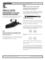
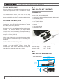
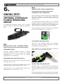
O P E R AT O R I N S T R U C T I O N M A N U A L
SWi12/14TM
SWi20/25TE
SWi20/25TI
FLANGE
SPREADING
WEDGES
E Q UA L I Z E R I N T E R N AT I O N A L LT D
w w w. e q u a l i z e r i n t e r n a t i o n a l . c o m
OP E R ATOR I NS TR UC TI O N M A NUA L
I M _ S W i _ REV 0 7 _ A4_E n g lish
CONTENTS
1.INTRODUCTION
2.
TOOL SAFETY
2.1
GENERAL SAFETY
2.2
PERSONNEL COMPETENCY
2.3 DISCLAIMER
2.4
DEFINITION OF TERMS
2.5
HAZARDS
3.
GENERAL SPREADING WEDGE TOOL OPERATION
3.1
GENERAL GUIDANCE
3.2
FLANGE SPREADING
3.3
FLANGE WORK
3.4
FLANGE CLOSURE
3.5
SAFETY BLOCKS
3.6
STEPPED BLOCKS
3.7
HANDLE
3.8
LANYARD
3.9
STEP DIMENSIONS & SPREADING DISTANCES
4.
TOOL MAINTENANCE
4.1
INSPECTION
4.2
CLEANING
4.3 MAINTENANCE
4.4
LUBRICATION
4.5
STORAGE & TRANSPORTATION
4.6 OPERATING CONDITIONS
4.7
SUB-SEA USAGE
5.SWi12/14TM
5.1
TOOL CAPABILITIES
5.2
TOOL FUNCTION
5.3
KIT CONTENTS
5.4
DIMENSIONS
6.SWi20/25TI
6.1
TOOL CAPABILITIES
6.2
TOOL FUNCTION
6.3
KIT CONTENTS
6.4
DIMENSIONS
7.SWi20/25TE
7.1
TOOL CAPABILITIES
7.2
TOOL FUNCTION
7.3
KIT CONTENTS
7.4
DIMENSIONS
8.TROUBLESHOOTING
8.1 SWi GENERAL TROUBLESHOOTING
8.2
SWi12/14TM TROUBLESHOOTING
8.1
SWi20/25TI TROUBLESHOOTING
8.2
SWi20/25TE TROUBLESHOOTING
9. REGULATORY INFORMATION
9.1
REGISTERED HEAD OFFICE
9.2
APPLICABLE PATENT NUMBERS
10.
PARTS LISTS & SERVICE KITS
29/08/14
SWi12/14TM; SWi20/25TE; SWi20/25TI
2
FLANGE SPREADING WEDGES
OP E R ATOR I NS TR UC TI O N M A NUA L
I M _ S W i _ REV 0 7 _ A4_E n g lish
1.
2.
INTRODUCTION
TOOL SAFETY
The Equalizer™ SWi Innovative Range of Flange
Spreading Wedge tools has been developed to assist in
the spreading of all flange joint types with a minimum
access gap of 6.0mm (0.24”). The tools can be used
during pipework construction, commissioning or during
routine maintenance.
2.1
GENERAL SA F ETY
These instructions cover the safe operation and
maintenance of THE EQUALIZER SWi12/14TM,
SWi20/25TE and SWi20/25TI FLANGE SPREADING
WEDGE tools. The use of these tools should be as part
of a broader task-based risk assessment, which should be
carried out by the operation supervisor or other competent
person.
The SWi tools have less moving parts and no finger pinch
points. The tools have been developed to increase the
spreading distance on each step while gaining easier
access between any remaining stud-bolts within the
flange joint. The tools provide a much higher spreading
force than the existing SW flange spreading tools. The
SWi tools are supplied with a swivel handle, safety lanyard
and stepped block attachment as standard.
Failure to comply with the safety information contained
within this manual could result in personal injury or
equipment damage. Read all instructions, warnings and
cautions carefully, and follow all safety precautions.
The safety of the operator, any assisting personnel and
the general public is of paramount importance. Always
work in accordance with applicable national, local, site &
company-wide safety procedures.
2.2
PERSONNEL COMPETENCY
Only personnel deemed competent in the use of mechanical
and hydraulic equipment should use these tools.
2.3
It is essential that the user familiarises themselves with
the contents of this manual prior to using the tool.
DISCL A IMER
This manual contains information for the following tools:
•
•
•
Equalizer cannot be held responsible for injury or damage
resulting from unsafe product use, lack of maintenance
or incorrect product and/or system operation. If in doubt
as to the safety precautions and applications, contact
Equalizer using the contact details at the back of this
manual.
SWi12/14TM Mechanical Flange Spreading Wedge
SWi20/25TI Integral Hydraulic Flange Spreading
Wedge
SWi20/25TE External Hydraulic Flange Spreading
Wedge
SWi12/14TM; SWi20/25TE; SWi20/25TI
3
FLANGE SPREADING WEDGES
OP E R ATOR I NS TR UC TI O N M A NUA L
2.4
I M _ S W i _ REV 0 7 _ A4_E n g lish
risks, such as heavy objects or vehicles; crush damage
can cause hose failure.
D EFI NIT IO N OF T E R MS
WARNING: Applying pressure to a damaged
hose may cause it to rupture.
A CAUTION is used to indicate correct operating or
maintenance procedures and practices to prevent damage
to, or destruction of equipment or other property.
WARNING: Immediately replace worn or
damaged parts. Use only genuine Equalizer
parts from approved distributors or service
centres. Equalizer parts have been engineered
and manufactured to be fit-for-purpose.
A WARNING indicates a potential danger that requires
correct procedures or practices to avoid personal injury.
A DANGER is only used when your action or lack of action
may cause serious injury or even death.
DANGER: To minimise risk of personal injury
keep hands and feet away from the tool and
workpiece during operation.
DO: an illustration showing how the tool should
be used.
WARNING: Always wear suitable clothing and
Personal Protective Equipment (PPE). Do not
handle pressurised hoses; escaping oil under
pressure can penetrate the skin, causing serious
injury. Seek medical attention immediately if oil
penetration is suspected.
DON’T: an illustration showing an incorrect way
to use a tool.
WARNING: Only pressurize complete and fully
connected hydraulic systems. Do not pressurize
systems that containt unconnected couplers.
2.5
H AZ AR DS
CAUTION: Do not lift hydraulic equipment by
the hoses or couplers. Use only the designated
carrying handles.
WARNING: ensure all hydraulic components are
rated to a safe working pressure of 700bar
(10,000psi).
CAUTION: Lubricate tools as directed in this
manual prior to operation. Use only approved
lubricants of high quality, following the lubricant
manufacturers instructions.
WARNING: Do not overload equipment. The
risk of hydraulic overloading can be minimised
by using the Equalizer Hand Pump, which has a
factory-set safety valve preventing the safe
working pressure being exceeded.
CAUTION: Only use the designated anchor
point for fixing the lanyard. Do not attach the
lanyard to the plastic handle.
If alternative hydraulic pumps are used, ensure
that there are adequate systems to limit the
the working pressure to 700 bar (10,000 psi).
DANGER: Care should be taken when using the
lanyard to avoid entanglement with body parts.
CAUTION: ensure components are protected
from external sources of damage, such as
excessive heat, flame, moving machine parts,
sharp edges and corrosive chemicals.
CAUTION: Take care to avoid sharp bends and
kinks in hydraulic hoses. Bends and kinks can
cause severe back-up pressure and cause hose
failure. Protect hoses from dropped objects; a
sharp impact may cause internal damage to
hose wire strands. Protect hoses from crush
SWi12/14TM; SWi20/25TE; SWi20/25TI
4
FLANGE SPREADING WEDGES
OP E R ATOR I NS TR UC TI O N M A NUA L
I M _ S W i _ REV 0 7 _ A4_E n g lish
3.
SWi SPREADING WEDGE
TOOL OPERATION
3.1
GENE R A L G U IDANC E
Before attaching the tool ensure at least two flange bolts
remain in place. These should be 180 degrees apart with
their nuts loosened sufficiently to enable flange work to
be carried out. Leaving these bolts in place will help to
reduce unwanted lateral flange movement during flange
spreading.
3.2
F L ANGE SPREADING
Spread the flanges apart by actuating the tool. Consult
the relevant section of the manual for tool-specific
instructions on how to actuate each tool.
Once the joint has been opened to the desired distance,
or if the tool has reached its maximum travel, insert the
Safety Blocks into the flange joint.
Prior to spreading, an assesment should be carried out to
determine the most appropriate positioning of the tools
around the joint. A minimum of 2 tools should always be
used.
Ensure the full width of the selected Safety Block step is
fully inserted before gradually retracting the tool until the
flange load has been applied to them.
Determine the flange joint access gap - a minimum access
gap of 6 mm (0.24”) is required for the SWi tools. The
access gap is the clearance between the surfaces onto
which the wedge will apply its spreading force.
6.0mm (0.24”)
MINIMUM
ACCESS GAP
The wedges can then be retracted fully and inserted
again, using the next step. In this way the flange joint
can be iteratively opened further until the required spread
is reached.
Place the tool into the access gap, with the full width of
the selected step fully inserted up to the heel.
SWi12/14TM; SWi20/25TE; SWi20/25TI
5
FLANGE SPREADING WEDGES
OP E R ATOR I NS TR UC TI O N M A NUA L
3.3
3.5
FL A NG E W O R K
SA F ETY BL OCK S
Do not rely upon hydraulic systems for
supporting the access gap during flange work.
Do not allow fingers, hands or other body parts
into the space created between the flanges.
I M _ S W i _ REV 0 7 _ A4_E n g lish
Each tool is supplied with a set of 2 Safety Blocks. The
Safety Blocks have been designed with steps that match
the spreading distance of the SWi tools.
3.4
FL A NG E C LO SU R E
Allow the flanges to return to their closed position by
gradually retracting the tool. Consult the relevant section
of the manual for tool-specific instructions on how to
retract each tool. Before the tool has fully retracted, insert
the Safety Blocks into the flange joint. Ensure the full
breadth of the selected Safety Block step is fully inserted,
before gradually retracting the tool until the flange load
has been applied to them.
3.6
STEPPED BL OCK S
The SWi Range of Flange Spreader tools are supplied
as standard with a pair of Stepped Blocks. These can
be fixed to the jaws (individually or in pairs) to increase
the effective jaw thickness and therefore the maximum
spreading distance.
Use of the Stepped Blocks also enables the SWi Flange
Spreaders to be used in a joint with a larger access gap.
Wedge protrusion can be minimised by the use of Stepped
Blocks, reducing the penetration into the joint. This
enables, for example, spectacle blinds to be changed.
Attach the stepped block to the tool using the M6 countersunk screw. Use the hex-key supplied to tighten the
screw into the threaded hole in the jaw of the tool. Repeat
for second Stepped Block to further increase the effective
jaw thickness if required.
To use the next smallest step, actuate the wedges to
around 75% prior to inserting back into the joint. Place
the tool in the gap and actuate enough to relieve the load
on the Safety Blocks. In this way the flange joint can be
progressively closed.
As the flange approaches its fully closed position, support
the tool to avoid it dropping out of the joint. Ensure that
care is taken to prevent objects being dropped. Dropped
objects pose a risk of personal injury or equipment
damage.
SWi12/14TM; SWi20/25TE; SWi20/25TI
6
FLANGE SPREADING WEDGES
OP E R ATOR I NS TR UC TI O N M A NUA L
I M _ S W i _ REV 0 7 _ A4_E n g lish
3.8
To remove the Stepped Blocks unscrew the M6 countersunk screw. Do not force the screw out of the Stepped
Block, it is deliberately retained to prevent it becoming
misplaced.
L ANYA RD
The SWi tools are supplied with a secure anchor point and
a lanyard. The lanyard should be used to minimise the
risks associated with the tool dropping.
Use the tool as per the Tool Operation instructions. Ensure
that there is a minimum hold of 15mm (0.59”) and that
the full width of the block is used.
Attach one end of the lanyard to the tool using the supplied
shackle. The other end of the lanyard should be fixed to
a secure point close to the work-site using an appropriate
shackle.
Avoid using the lanyard as a means for picking up or
carrying the tool. Do not fix the lanyard to the handle.
The anchor point and lanyard have been engineered to
safely sustain a drop over the full lanyard length. It is
recommended that all parts are inspected following a drop
incident, as damage may compromise the safety of the
tool.
15.0mm (0.59”)
MINIMUM HOLD
CAUTION: Only use the designated anchor
point for fixing the lanyard. Do not attach the
lanyard to the plastic handle.
3.7
DANGER: Care should be taken when using the
lanyard to avoid entanglement with body parts.
H ANDLE
The handle can be swivelled around the central axis of the
tool, to improve access to the Flange and allow the tool
to be easily held in the vertical or horizontal orientation.
If the tool is being used in an application where access
space is very limited, the handle can be removed
temporarily. Unclip the spiral ring and remove the anchor
point and handle. Special caution should be exercised
when working with a tool in this configuration. Replace
the handle immediately following the task.
HANDLE
SPIRAL RING
ANCHOR POINT
SWi12/14TM; SWi20/25TE; SWi20/25TI
7
FLANGE SPREADING WEDGES
OP E R ATOR I NS TR UC TI O N M A NUA L
SWi12/14TM; SWi20/25TE; SWi20/25TI
8
I M _ S W i _ REV 0 7 _ A4_E n g lish
FLANGE SPREADING WEDGES
OP E R ATOR I NS TR UC TI O N M A NUA L
3.9
I M _ S W i _ REV 0 7 _ A4_E n g lish
SAFETY BLOCK DIMENSIONS
9
(3 4.0
.7 m
0 m
10 ”)
(3 0.0
.9 m
4” m
)
S TEP DI M E NSI ONS & SP R E ADI NG
3
(1 8.0
.5 m
0” m
52 )
(2 .0
.0 m
5 m
68 ”)
(2 .0
.6 m
8 m
81 ”)
(3 .0
.1 m
9” m
)
D I S T A NCE S
LARGE SAFETY BLOCK
SMALL SAFETY BLOCK
4
(1 0.0
.5 m
7” m
55 )
(2 .5
.1 m
9 m
7 ”)
(2 1.5
.8 m
1” m
8 )
(3 7.5
.4 m
4” m
)
6
(0 .0m
.2 m
4”
21 )
(0 .5
.8 m
5 m
3 ”)
(1 7.5
.4 m
8 m
5 ”)
(2 3.5
.1 m
1” m
)
JAW DIMENSIONS (WITHOUT STEPPED BLOCKS ATTACHED)
TOOL CLOSED
TOOL OPEN
8
(3 2.5
.2 m
5” m
10 )
(4 3.5
.0 m
7” m
)
4
(1 8.5
.9 m
1” m
)
69
(2 .5
.7 m
4” m
)
JAW DIMENSIONS (WITH STEPPED BLOCKS ATTACHED)
TOOL CLOSED
SWi12/14TM; SWi20/25TE; SWi20/25TI
9
TOOL OPEN
FLANGE SPREADING WEDGES
OP E R ATOR I NS TR UC TI O N M A NUA L
4.
4.3
SERVICING
Replace missing worn or damaged parts. Use only
genuine Equalizer parts from approved distributors or
service centres. Equalizer parts have been engineered and
manufactured to be fit-for-purpose.
TOOL MAINTENANCE
4.1
Grease all moving parts by following the Lubrication
Procedure prior to usage, storage or transportation.
I NS P E C T IO N
Do not exceed 5.0N.m (3.68ft.lb) of torque when
tightening the Jaw retaining screws. The jaws have been
engineered to have a small degree of movement when
correctly tightened.
A thorough inspection should be carried out prior to usage,
storage or transportation to ensure the completeness and
condition of the tool.
Inspection should include:
•
•
I M _ S W i _ REV 0 7 _ A4_E n g lish
If topping up or replacing hydraulic oil as part of a service,
use only premium quality hydraulic oil of the grade 15cSt.
visual inspection of the outer parts of the tool,
checking for obvious damage, degradation or missing
parts
visual inspection of the wedge-tip (requiring tool
actuation or jaw removal). Damage to the wedge-tip
is indicative of tool over-load.
4.4
L UBRICA TION PROCEDURE
Cleaning and servicing should be undertaken as required
prior to the tool being used, stored or transported.
Apply grease following cleaning and servicing, prior to
usage, storage or transportation. Never assemble and
leave a tool without following the greasing procedure as
degradation or damage may occur.
4.2
Use only high pressure molybdenum disulphide grease.
CL EANING
Remove the jaws as per the dissassembly instructions.
To lightly clean the tool, wipe gently with a damp cloth.
Apply grease liberally to the following areas:
If more thorough cleaning is required (for example
following immersion in water) carry out the following
cleaning procedure:
•
•
•
•
•
•
strip the tool down, observing the schematics in
section 10.
clean the components using detergent, following the
manufacturer’s guidelines
rinse the components to remove traces of detergent
dry the components thoroughly
4.5
STORAGE & TRA NSPORTATION
Equalizer tools should be stored in a cool dry place. Tools
should always be cleaned, serviced and lubricated prior to
storage. Ensure that tools are stored in their designated
packing cases.
Inspect, service and lubricate the tool immediately after
the cleaning process.
SWi12/14TM; SWi20/25TE; SWi20/25TI
the large flat surface on the underside of the jaws
the internal flat surfaces in the square cut-out in the
jaws
10
FLANGE SPREADING WEDGES
OP E R ATOR I NS TR UC TI O N M A NUA L
I M _ S W i _ REV 0 7 _ A4_E n g lish
4.6
Using SWi20/25TE Sub-Sea
OPERA T I NG CONDI T I ONS
The SWi20/25TE is actuated by means of single-acting
spring-return hydraulic cylinder and can be used sub-sea
providing the following actions are taken:
GREASE LIMITATIONS:
Minimum Temperature:
Maximum Temperature:
•
-5ºC (23ºF)
40ºC (104ºF)
MECHANICAL TOOLS:
Minimum Jaw Contact Temperature: Maximum Jaw Contact Temperature:
•
-30ºC (-22ºF)
150ºC (302ºF)
•
HYDRAULIC TOOLS:
Minimum Jaw Contact Temperature: Maximum Jaw Contact Temperature:
•
•
-30ºC (-22ºF)
70ºC (158ºF)
•
4.7
S U B - SE A U SAGE
Please note that a sub-sea SWi20/25TE tool cannot be
operated from top-side by use of a down-line. The return
springs in the hydraulic cylinders do not have sufficient
force to close the tool if used with a down-line from a
top-side pump, therefore the standard hydraulic tools will
not function correctly and may jam in place if used in this
configuration.
The Equalizer range of HP hydraulic hand pumps are fitted
with a sealed-bladder type reservoir system that allows
for sub-sea operation.
Using SWi12/14TM Sub-Sea
The SWi20/25TM is actuated mechanically and can be
used sub-sea providing the following actions are taken:
•
•
The gauge and manifold are removed from the
Equalizer HP350S/D hydraulic hand-pump and the
coupler is fitted directly to the pump outlet (tools in
this configuration can be requested from Equalizer).
The tool is connected to the Equalizer HP350S/D
pump whilst still top-side.
The pump release valve is fully opened and remains
open until the tool has descended to the working
depth. This will allow the pressure to equalise.
The tool is actuated via the hand pump by a diver.
Upon completion of works the release valve is left in
the fully-open position until the tool has ascended to
the surface.
The tool and pump are stripped-down, cleaned and
lubricated immediately to minimise corrosion.
The tool is actuated via the torque-wrench by a diver.
The tool and pump are stripped-down, cleaned and
lubricated immediately to minimise corrosion.
Using SWi20/25TI Sub-Sea
The SWi20/25TI is actuated by means of single-acting
spring-return hydraulic cylinder and can be used sub-sea
providing the following actions are taken:
•
•
•
•
The pump release valve is fully opened and remains
open until the tool has descended to the working
depth. This will allow the pressure to equalise.
The tool is actuated via the hand pump by a diver.
Upon completion of works the release valve is left in
the fully-open position until the tool has ascended to
the surface.
The tool and pump are stripped-down, cleaned and
lubricated immediately to minimise corrosion.
SWi12/14TM; SWi20/25TE; SWi20/25TI
11
FLANGE SPREADING WEDGES
OP E R ATOR I NS TR UC TI O N M A NUA L
5.
I M _ S W i _ REV 0 7 _ A4_E n g lish
5.2
SWi12/ 14TM TOOL F UNCTION
MECHANICAL TOOL OPERATION
SWi12/14TM
The SWi12/14TM Spreading Wedge uses mechanical
torque to advance the wedge and spread the jaws. The
torque is applied using the supplied Torque Wrench,
enabling accurate control of the force applied.
MECHANICAL FLANGE
SPREADING WEDGE
The SWi12/14TM Spreading Wedge uses mechanical
torque to advance the wedge and spread the jaws.
TORQUE WRENCH USAGE
Holding the Torque Wrench in one hand, unlock the
knurled handle by turning the locking knob anti-clockwise.
Select the torque setting by turning the knurled handle
until the required torque value is indicated.
For example, to set the Torque Wrench to 46Nm: turn the
knurled handle until the 0 on the fine scale aligns with
40Nm on base scale; now turn slightly further until the 6
on the fine scale aligns with the central line.
5.1
S Wi1 2/ 14T M T OOL C AP ABI LI T IES
Setting an imperial torque (in ft.lb) is done in exactly the
same way.
SPREADING FORCE
Maximum SWL torque of 175N.m (130ft.lb) will generate
12T (120kN) spreading force on the 1st step and 14T
(140kN) spreading force on the 4th step.
Lock the handle by turning the locking knob clockwise.
Install the supplied socket onto the Torque Wrench and
attach to the tool.
Slowly and smoothly pull the handle, gradually applying
more force until you feel or hear the Torque Wrench click,
indicating that the selected torque has been achieved. Do
not continue to apply force after the Torque Wrench has
clicked. Special care should be taken when using low
torque settings.
SWi12/14TM; SWi20/25TE; SWi20/25TI
12
FLANGE SPREADING WEDGES
OP E R ATOR I NS TR UC TI O N M A NUA L
I M _ S W i _ REV 0 7 _ A4_E n g lish
TORQUE WRENCH CARE
5.3
Prior to storing the Torque Wrench, and between use,
leave the Torque Wrench with its lowest torque setting
selected.
SWi12/ 14TM K IT CONTENTS
STANDARD KIT
To clean the Torque Wrench, wipe gently with a damp
cloth. Avoid using any detergent or solvent as this may
detrimentally affect the factory-fitted internal lubrication
of the mechanism.
Product Code: SWi1214TMSTDSPB
1 x SWi12/14TM Mechanical Flange Spreader Wedgehead
1 x Mechanical Cylinder
1 x Torque Wrench with 22mm Socket
1 x Set of Safety Blocks
1 x Pair of Stepped Blocks
1 x Lanyard
1 x Hex Key
1 x Instruction Manual
1 x Plastic Carry Case
ACTUATING THE SWi12/14TM
Follow the SWi Spreading Wedge Tool Operation
instructions, using the following instructions to actuate
the SWi12/14TM tool in particular:
Actuate the tool by manually applying force to the torque
wrench in the clockwise direction (see Torque Wrench
Usage). Gradually increase the torque setting of the
Torque Wrench over several steps, for example 30Nm (or
20ft.lb) each time. Do not exceed the maximum SWL
torque of 175N.m (130ft.lb).
When using multiple tools, ensure that the torque settings
of all wrenches correspond to keep the spreading force
balanced.
RETRACTING THE SWi12/14TM
580mm x 330mm x 165mm (22.8” x 13.0” x 6.5”)
Retract the tool by manually applying force to the torque
wrench in the anti-clockwise direction. When using
multiple tools, work around all wrenches to keep the
spreading force balanced as the gap is closed.
Gross kit weight: Tool only weight: 13.0kg (28.6lb)
6.2kg (13.7lb)
5.4
SWi12/ 14TM DIMENSIONS
TOOL DIMENSIONS
- CLOSED
152mm
(6.0”)
290mm
(12.3”)
270mm
(11.4”)
60mm
(2.4”)
6.0mm
(0.24”)
SWi12/14TM; SWi20/25TE; SWi20/25TI
13
FLANGE SPREADING WEDGES
OP E R ATOR I NS TR UC TI O N M A NUA L
6.
I M _ S W i _ REV 0 7 _ A4_E n g lish
6.2
SWi20/ 25TI TOOL F UNCTION
HYDRAULIC TOOL OPERATION
SWi20/25TI
Prior to operation, ensure the air-vent in the integral hand
pump is not obstructed. Any obstruction in the air-vent
can cause a vacuum in the system which can limit the
cylinder’s travel.
INTEGRAL HYDRAULIC
FLANGE SPREADING
WEDGE
The SWi20/25TI Spreading Wedge uses a hydraulic
cylinder to advance the wedge and spread the jaws. The
hydraulic pressure is applied using the integrated hand
pump, enabling accurate control of the force applied.
The SWi20/25TI Spreading Wedge uses an integral
hydraulic cylinder to advance the wedge and spread the
jaws.
The integral hand pump has a control lever which allows
the user to select advance (+) or retract (-).
ACTUATING THE SWi20/25TI
S Wi2 0/ 25T I T OOL C AP ABI LI T I ES
Follow the SWi Spreading Wedge Tool Operation
instructions, using the following instructions to actuate
the SWi20/25TI tool in particular:
SPREADING FORCE
When advance (+) is selected, pumping the handle will
advance the cylinder and spread the jaws.
6.1
With the maximum hydraulic pressure of 700bar
(10,000psi) applied, the tool can apply 20T (200kN)
spreading force on the 1st step, up to 24T (240kN)
spreading force on the 4th step.
SPREADING GAP (SEE SECTION 3.9)
Using only the 1st step, the tool can spread from 6.0mm
to 40.0mm (0.24” - 1.6”).
RETRACTING THE SWi20/25TI
Using all 4 steps, but without the stepped blocks, the tool
can spread from 6.0mm to 87.5mm (0.24” - 3.4”).
Selecting retract (-) will depressurise the cylinder and
cause it to retract under the force of its internal spring.
The handle does not need to be pumped to retract the
tool.
Using both steps on the stepped blocks, the tool can
spread 48.5mm – 103.5mm (1.9” - 4.1”).
When using multiple tools, exercise caution while retracting
to keep the spreading force balanced as the gap is closed.
SWi12/14TM; SWi20/25TE; SWi20/25TI
14
FLANGE SPREADING WEDGES
OP E R ATOR I NS TR UC TI O N M A NUA L
I M _ S W i _ REV 0 7 _ A4_E n g lish
AIR RELIEF INSTRUCTIONS
6.3
In the event of air build-up within the cylinder-pump
subassembly, the following procedure should be executed:
SWi20/ 25TI K IT CONTENTS
STANDARD KIT
Select advance (+), and pump the handle to extend the
piston around 30mm (1.2”). Remove the Oil Fill Screw
using an appropriate hex key, ensuring the tool is on its
side with the Oil Fill facing upwards (top photo).
Product Code: SWi2025TISTDSPB
1
1
1
1
1
1
1
1
1
x
x
x
x
x
x
x
x
x
SWi20/25TI Flange Spreader Wedgehead
10,000psi (700bar) Integral Hydraulic Pump/Cylinder
Set of Safety Blocks
Pair of Stepped Blocks
Lanyard
Hex Key
Carry-Strap
Instruction Manual
Carry Case
580mm x 330mm x 165mm (22.8” x 13.0” x 6.5”)
Gross kit Weight Tool only weight: 13.8kg (30.4lb)
8.5kg (18.7lb)
6.4
SWi20/ 25TI DIMENSIONS
Replenish any missing hydraulic oil by pouring into the Oil
Fill hole until excess spills over (middle photo).
TOOL DIMENSIONS
- CLOSED
465mm
(18.3”)
Sit the tool with the wedge facing uphill (and the open Oil
Fill hole still facing upwards) on a gentle slope, around 30
degrees from horizontal.
152mm
(6.0”)
60mm
(2.4”)
Very slowly move the selector from advance (+) to retract
(-), and wait for the tool to fully retract (lower photo).
Replace the Oil Fill Screw.
6.0mm
(0.24”)
Repeat this procedure 3 times.
SWi12/14TM; SWi20/25TE; SWi20/25TI
15
FLANGE SPREADING WEDGES
OP E R ATOR I NS TR UC TI O N M A NUA L
7.
I M _ S W i _ REV 0 7 _ A4_E n g lish
7.2
SWi20/ 25TE TOOL F UNCTION
HYDRAULIC TOOL OPERATION
SWi20/25TE
The SWi20/25TE Spreading Wedge uses a hydraulic
cylinder to advance the wedge and spread the jaws.
The hydraulic pressure is applied using an external hand
pump, enabling accurate control of the force applied.
HYDRAULIC FLANGE
SPREADING WEDGE
HAND PUMP OPERATION
The SWi20/25TE Spreading Wedge uses an external
hydraulic pump to drive the cylinder to advance the wedge
and spread the jaws.
Consult the Instruction Manual for the Equalizer HP HandPump supplied in the kit.
ACTUATING THE SWi20/25TE
Follow the SWi Spreading Wedge Tool Operation
instructions, using the following instructions to actuate
the SWi20/25TE tool in particular:
When the Hand-Pump release valve is closed, pumping
the Hand-Pump handle will advance the cylinder and
spread the jaws.
When using multiple tools, ensure that the spread of all
tools correspond to keep the spreading force balanced.
7.1
S Wi2 0/ 25T E T OOL C AP ABI LI T I ES
The Maxi-kit includes a twin-port hand pump which can
be used to actuate two tools simultaneously.
SPREADING FORCE
RETRACTING THE SWi20/25TE
With 700bar (10,000psi) of hydraulic pressure applied,
the tool can apply 20T (200kN) spreading force on the 1st
step, up to 24T (240kN) spreading force on the 4th step.
Opening the release valve will depressurise the cylinder
and cause it to retract under the force of its internal
spring. The handle does not need to be pumped to retract
the tool.
SPREADING GAP (SEE SECTION 3.9)
When using multiple tools, exercise caution while retracting
to keep the spreading force balanced as the gap is closed.
Using only the 1st step, the tool can spread from 6.0mm
to 40.0mm (0.24” - 1.6”).
AIR-LOCK RELIEF
Using all 4 steps, but without the stepped blocks, the tool
can spread from 6.0mm to 87.5mm (0.24” - 3.4”).
If full pressure is not achieved an air-lock may be present
in the hydraulic system. The following procedure can be
executed to relieve any air-locks.
Using both steps on the stepped blocks, the tool can
spread 48.5mm – 103.5mm (1.9” - 4.1”).
SWi12/14TM; SWi20/25TE; SWi20/25TI
Connect the hand pump to the tool with the hydraulic
hose. Close the release valve on the pump, and prime the
pump until the hydraulic cylinder is fully extended and a
small pressure is achieved.
16
FLANGE SPREADING WEDGES
OP E R ATOR I NS TR UC TI O N M A NUA L
With the hand pump elevated above the level of the tool,
and the tool in an upright position, open the hand pump
release valve causing any air that is within the system to
be forced up through the pump and vented into the oil
reservoir.
I M _ S W i _ REV 0 7 _ A4_E n g lish
580mm x 330mm x 165mm (22.8” x 13.0” x 6.5”)
Gross kit Weight Tool only weight: 11.6kg (25.6lb)
6.4kg (14.1lb)
STANDARD KIT
Repeat this process three further times to ensure that all
air is removed from the system. The tool should now
reach full working pressure
Product Code: SWi2025TESTDSPB
1 x SWi20/25TE Flange Spreader Wedgehead
1 x 10,000psi (700bar) Hydraulic Cylinder
1 x 10,000psi (700bar) Hydraulic Hose, 2m (78.75”) with
90 degree elbow
1 x 10,000psi (700bar) HP350S Sealed Hand Pump with
Gauge
1 x Set of Safety Blocks
1 x Pair of Stepped Blocks
1 x Hex Key
1 x Lanyard
1 x Set of Instruction Manuals
1 x Plastic Carry Case
Disconnect the hand pump from the hydraulic hose,
grip the baseplate of the hand pump body in a vice with
the pump body vertical and the main handle at the top.
Remove the four nuts holding the main handle and lift off.
Grip the refilling plug with pliers and extract it by pulling
and twisting simultaneously. Ensure the reservoir body
is held down when removing the refilling plug as pulling
up on the reservoir body will release the bladder within,
and oil may spill out. Fill the reservoir to the top with a
premium quality hydraulic oil of the grade 15 cSt. Reinsert
the refilling plug, wipe away any oil, and reassemble by
reversing the disassembly process.
7.3
S W i20/ 25T E KI T C ONT E NT S
MINI KIT
Product Code: SWi2025TEMIN
1
1
1
1
1
1
1
1
x
x
x
x
x
x
x
x
SWi20/25TE Flange Spreader Wedgehead
10,000psi (700bar) Hydraulic Cylinder
Set of Safety Blocks
Pair of Stepped Blocks
Hex Key
Lanyard
Instruction Manual
Plastic Carry Case
SWi12/14TM; SWi20/25TE; SWi20/25TI
920mm x 500mm x 205mm (36.2” x 19.7” x 8.1”)
Gross kit Weight Tool only weight: 17
20.7kg (45.6lb)
6.4kg (14.1lb)
FLANGE SPREADING WEDGES
OP E R ATOR I NS TR UC TI O N M A NUA L
I M _ S W i _ REV 0 7 _ A4_E n g lish
MAXI KIT
Product Code: SWi2025TEMAXSPB
2 x SWi20/25TE Flange Spreader Wedgeheads
2 x 10,000psi (700bar) Hydraulic Cylinders
2 x 10,000psi (700bar) Hydraulic Hoses, 2m (78.75”) with
90 degree elbow
1 x 10,000psi (700bar) HP550D Sealed Hand Pump with
Gauges
2 x Sets of Safety Blocks
2 x Pairs of Stepped Blocks
2 x Hex Keys
2 x Lanyards
1 x Set of Instruction Manuals
1 x Plastic Carry Case
920mm x 500mm x 205mm (36.2” x 19.7” x 8.1”)
Gross kit Weight Tool only weight: 33.0kg (72.8lb)
6.4kg (14.1lb)
7.4
S Wi2 0/ 25T E DI ME NSI ONS
TOOL DIMENSIONS
- CLOSED
152mm
(6.0”)
312mm
(12.3”)
270mm
(10.6”)
60mm
(2.4”)
6.0mm
(0.24”)
SWi12/14TM; SWi20/25TE; SWi20/25TI
18
FLANGE SPREADING WEDGES
OP E R ATOR I NS TR UC TI O N M A NUA L
8.
I M _ S W i _ REV 0 7 _ A4_E n g lish
distributor for repair.
POSSIBLE CAUSE:
The inlet check-valve or intermediate valve ball has
become stuck.
TROUBLESHOOTING
RECOMMENDED ACTION:
Dismantle the check valve, free and clean the valve
balls. Refer to an approved Equalizer distributor for
repair.
8.1
S W i20/ 25T I TR OU BLE SHOOT I NG
THE WEDGE MOVES AS INTENDED, BUT
DOESN’T SEEM TO BE ACHIEVING FULL
PRESSURE WHEN UNDER LOAD
THE WEDGE ADVANCES SOME OF THE WAY
AND THEN STOPS PROGRESSING
POSSIBLE CAUSE:
Intermediate valve not seating / relief valve leaking.
POSSIBLE CAUSE:
The air-vent is obstructed by dirt or debris.
RECOMMENDED ACTION:
Check cleanliness of valve ball. Re-seat using a
hammer and punch. Refer to an approved Equalizer
distributor for further instruction.
RECOMMENDED ACTION:
Carefully unblock the air-vent using a small blunt
object.
HYDRAULIC PRESSURE SLOWLY DIMINISHES
AND THE PUMP HANDLE RISES
THE WEDGE DOESN’T MOVE
POSSIBLE CAUSE:
POSSIBLE CAUSE:
There is an air-lock within the hydraulic system.
The outlet check valve is leaking.
RECOMMENDED ACTION:
RECOMMENDED ACTION:
Select Retract (-) and prime pump to circulate oil
around the system.
Check cleanliness of valve ball. Re-seat using a
hammer and punch. Refer to an approved Equalizer
distributor for further instruction.
POSSIBLE CAUSE:
Insufficient oil in the hydraulic system.
HYDRAULIC PRESSURE SLOWLY DIMINISHES
AND THE PUMP HANDLE DOES NOT RISE
RECOMMENDED ACTION:
Refill with clean oil and bleed the hydraulic system.
POSSIBLE CAUSE:
The release valve is leaking.
POSSIBLE CAUSE:
RECOMMENDED ACTION:
Retract (-) is selected.
Refer to an approved Equalizer distributor for further
instructions.
RECOMMENDED ACTION:
Select Advance (+) and pump the handle.
POSSIBLE CAUSE:
POSSIBLE CAUSE:
The piston seal is leaking.
Air has accumulated around pump inlet when used
upside down.
RECOMMENDED ACTION:
Inspect the tool for oil leaks, possibly indicative
of a perished seal or loose blanking plug. Refer
to an approved Equalizer distributor for further
instructions.
RECOMMENDED ACTION:
Bleed any air from the hydraulic reservoir. Inspect the
tool for oil leaks on the reservoir, possibly indicative
of a perished bladder. Refer to an approved Equalizer
SWi12/14TM; SWi20/25TE; SWi20/25TI
19
FLANGE SPREADING WEDGES
OP E R ATOR I NS TR UC TI O N M A NUA L
I M _ S W i _ REV 0 7 _ A4_E n g lish
TOOL ACTUATION FEELS SOFT AND
UNRESPONSIVE
POSSIBLE CAUSE:
There is air in the hydraulic system.
RECOMMENDED ACTION:
Bleed the hydraulic system. Refer to an approved
Equalizer distributor for further instruction.
8.2
S Wi2 0/ 25T E T R OU BLE SHOOT I NG
THE WEDGE IS ADVANCING BUT DOES NOT
REACH FULL PRESSURE
POSSIBLE CAUSE:
There is air in the hydraulic system.
RECOMMENDED ACTION:
Follow the Airlock Relief instructions.
SWi12/14TM; SWi20/25TE; SWi20/25TI
20
FLANGE SPREADING WEDGES
OP E R ATOR I NS TR UC TI O N M A NUA L
I M _ S W i _ REV 0 7 _ A4_E n g lish
9.
REGULATORY
INFORMATION
9.1
R EG I S T E R E D HE AD OFFI C E
EQUALIZER INTERNATIONAL LTD.
Equalizer House
Claymore Drive
Aberdeen
Scotland
AB23 8GD
9.2
A PP L I CA B LE P AT E NT NU MBE R S
The following list of Patents are applicable to EQUALIZER
INTERNATIONAL LTD SWi12/14TM, SWi20/25TI and
SWi20/25TE tools:
REGISTERED DESIGNS
•
•
•
•
•
•
•
•
002224980-0001
002224980-0002
002224980-0003
002224980-0004
84204
353180
256685
2L201330454407.8
REGISTERED PATENTS
•
•
•
•
•
•
•
•
•
•
WO01/66191
1259293B
6880809
WO98/47809
2328671B
219545
70630/98
316596
6267354
1012105B
SWi12/14TM; SWi20/25TE; SWi20/25TI
21
FLANGE SPREADING WEDGES
OP E R ATOR I NS TR UC TI O N M A NUA L
I M _ S W i _ REV 0 7 _ A4_E n g lish
10.
PARTS LISTS
& SERVICE KITS
SWi12/14TM; SWi20/25TE; SWi20/25TI
22
FLANGE SPREADING WEDGES
SWi12/14TM PARTS LIST
850000-01 REV.02
ITEM
NO.
PART NO
1
2
3
4
DESCRIPTION
QTY.
830201-01
WEDGE
1
830202-01
WEDGE TIP
1
830400-01
HANDLE
1
830500-01
CAPTIVE FASTENER
2
5
830600-01
LUGS
1
6
830800-01
ANCHOR POINT
1
7
830313-01
SPIRAL RETAINING RING
1
8
850300-01
MECHANICAL CYLINDER
1
9
830100-01
SWi JAW - SOLD IN PAIRS
2
RETAINING WASHER
2
M6 CSK HEX SCREW
3
WASHER (0.8MM)
2
M5 SCKT SET SCREW
1
14
M6 GRUB SCREW
2
15
DECAL WEDGE LRG
2
DECAL WEDGE SML
2
10
11
12
13
16
17
18
KIT
840140-01
KIT
840150-01
DECAL TI PUMP (SURPLUS IN TE & TM)
1
DECAL TM CYLINDER WRAP
1
ON REQUEST
3
7
6
18
15 16
14
12 10
13
8
13
1
10
12
5
2
11
11
15
14
4
9
MECHANICAL CYLINDER PARTS LIST
850300-01 REV.03
ITEM
NO.
PART NO
DESCRIPTION
QTY
1
850301-01
CYLINDER BASE
1
2
850302-01
DRIVE ROD
1
3
850303-01
CYL CAP
1
4
850304-01
PUSH ROD
1
5
850305-01
DRIVE HEX
1
6
850306-01
THREAD STOP
1
7
THRUST WASHER
2
8
THRUST RACE
1
DOWEL PIN
1
M6 CSK HEX SCREW
1
9
10
KIT
850110-01
5
9
3
7
2
10
1
4
6
8
7
SWi20/25TI PARTS LIST
840000-01 REV.03
ITEM
NO.
PART NO
1
830201-01
WEDGE
1
2
830202-01
WEDGE TIP
1
3
840300-01
H.CYLINDER & PUMP TI ASSEMBLY
1
4
830400-01
HANDLE
1
5
830500-01
CAPTIVE FASTENER
2
6
830600-01
LUGS
1
7
830800-01
ANCHOR POINT
1
8
830313-01
SPIRAL RETAINING RING
2
9
830100-01
SWi JAW - SOLD IN PAIRS
2
RETAINING WASHER
4
DESCRIPTION
10
11
KIT
840140-01
12
13
M6 CSK HEX SCREW
1
WASHER (0.8MM)
2
M5 SCKT SET SCREW
1
M6 GRUB SCREW
2
14
15
DECAL TI PUMP WRAP
1
DECAL WEDGE LRG
2
DECAL WEDGE SML
2
DECAL TI CYLINDER WRAP
1
KIT
840150-01
16
17
18
ON REQUEST
QTY
15
18
3
17
12
16
8
10
11
7
4
8
14
9
5
11
1
6
5
10
13
12
2
17
14
16
9
11
TI CYLINDER PARTS LIST
840300-01 REV.02
22
1 19 26
27
30
45
3
21
4
21
44
29
28
27
43
42
23
23 24
33
32
34
24
20
5 42 46 47
15
27
25
10
40
36
37
36
6 35 48 46 42 31
38
13
39
17
7
18
11
12
14
18
8
ITEM NO.
16
9
17
41
18
16
PART NO
KIT
840160-01
DESCRIPTION
QTY.
HANDLE CLEVIS
1
CLEVIS PIN
2
RETAINING RING
4
19
WIPER SEAL
1
20
TENSION DIE SPRING
1
21
SPRING LOCK
2
22
M6 CAPSCREW
1
O-RING
2
24
BACK-UP RING
2
25
SCREW
1
1
23
KIT
840110-01
26
M6 GASKET SEAL
27
O-RING
3
28
RELIEF VALVE SCREW
1
29
RELIEF VALVE KNOB
1
30
FIXING SCREW
1
31
OIL FILL SCREW
1
32
OVERLOAD COVER SCREW
1
33
CAP
1
34
O-RING
1
WASHER
1
O-RING
2
37
BACK UP RING
1
38
RESERVOIR BLADDER
1
O-RING
1
40
O-RING
1
41
PUMP PISTON ROD
1
KIT
840120-01
ITEM NO.
PART NO
DESCRIPTION
QTY.
35
1
830301-01
CYLINDER BODY
1
36
2
830310-01
CYL VENT PLUG
2
3
830302-01
PISTON
1
4
840100-01
NUT
1
39
5
840301-01
CYLINDER BASE
1
6
376901-01
PUMP PISTON HOUSING
1
7
840302-01
BLADDER HOUSING
1
8
372401-01
PISTON HOUSING CAP
1
9
372501-01
SWIVEL CLEVIS
1
10
373201-01
CLEVIS SCREW
1
11
373301-01
ANTI-LOOSEN NUT
1
12
373101-01
LINK CONNECTOR
1
13
372601-01
RETAINING NUT
1
47
14
373401-01
HANDLE ROD
1
48
SCREW
1
1
49
SPRING LOCK
1
15
306502-01
HANDLE GRIP
42
STEEL BALL
1
43
STEEL BALL
2
44
CONE SEAT
1
45
46
KIT
375020-01
CONE
1
LONG SEPARATOR SPRING
1
SPRING
2
SWi20/25TE PARTS LIST
830000-01 REV.02
ITEM
NO.
PART NO
1
2
DESCRIPTION
QTY
830201-01
WEDGE
1
830202-01
WEDGE TIP
1
3
830300-01
HYDRAULIC CYLINDER - 10,000 PSI
1
4
830313-01
SPIRAL RETAINING RING
2
5
830400-01
HANDLE
1
6
830500-01
CAPTIVE FASTENER
2
7
830600-01
LUGS
1
8
830800-01
ANCHOR POINT
1
9
830100-01
SWi JAW - SOLD IN PAIRS
2
RETAINING WASHER
4
M6 CSK HEX SCREW
2
WASHER (0.8MM)
6
M6 SCKT SET SCREW
1
14
M5 SCKT SET SCREW
4
15
DECAL WEDGE LRG
2
DECAL WEDGE SML
2
DECAL TI PUMP (SURPLUS FOR TE & TM)
1
SW TE CYLINDER WRAP
1
10
11
12
13
16
17
18
KIT
840140-01
KIT
840150-01
ON REQUEST
3
18
6
13
4
5
18
4
9
6
12
10
16
10
15
12
11
13
11
7
14
2
13
15
16
9
8
TE HYDRAULIC CYLINDER PARTS LIST
830300-01 REV.04
ITEM
NO.
PART NO
DESCRIPTION
QTY
1
830301-01
CYLINDER BODY
1
2
830302-01
PISTON
1
3
830303-01
CYL END CAP
1
4
771110-01
3/8" NPT COUPLER 10kPSI
1
6
WIPER SEAL
1
7
TENSION DIE SPRING
1
8
SPRING LOCK
2
9
M6 CAPSCREW
1
10
KIT
840110-01
O-RING
2
11
BACK-UP RING
2
12
M6X25 SCKT H. SCREW
1
13
M6 GASKET SEAL
1
6
1
9
13
2
10
7
11
4 12
3
10
8
11
SAFETY BLOCK SMALL
830021-01 REV.02
SAFETY BLOCK LARGE
830020-01 REV.02
STEP BLOCK (PAIR)
830050-01 REV.02
SAFETY BOND
830080-01 REV.01
SWi FASTENER SERVICE KIT
840140-01 REV.01
ITEM
NO.
DESCRIPTION
QTY.
1
RETAINING WASHER
4
2
M6 CSK HEX SCREW
5
3
WASHER (0.8MM)
2
4
M5 SCKT SET SCREW
1
5
M6 GRUB SCREW
2
6
M6 GRUB SCREW
2
7
4 MM ALLEN KEY
1
2
1
2
3
1
6
5
1
2
5
6
4
3
2
1
2
7
SWi DECAL SERVICE KIT
840150-01 REV.01
ITEM
NO.
DESCRIPTION
QTY/ASS
1
DECAL TI PUMP WRAP
1
2
DECAL WEDGE SML
2
3
DECAL WEDGE LRG
2
3 2
1
MECHANICAL CYLINDER SERVICE KIT
850110-01 REV.02
ITEM
NO.
DESCRIPTION
QTY
1
THRUST WASHER
2
2
THRUST RACE
1
3
DOWEL PIN
1
4
M6 CSK HEX SCREW
1
1
2
1
4
3
INTEGRAL BLADDER SERVICE KIT
840120-01 REV.02
ITEM
NO.
DESCRIPTION
QTY.
1
STEEL BALL
1
2
O-RING
3
3
RELIEF VALVE SCREW
1
4
RELIEF VALVE KNOB
1
5
FIXING SCREW
1
6
OIL FILL SCREW
1
7
OVERLOAD COVER SCREW
1
8
CAP
1
9
O-RING
1
10
WASHER
1
11
O-RING
2
12
BACK UP RING
1
13
O-RING
1
14
PUMP PISTON ROD
1
15
RESERVOIR BLADDER
1
16
O-RING
1
5
2
4
8
3
2
7
9
1
16
15
13
14
11
12
11
10
2
6
INTEGRAL MANIFOLD SERVICE KIT
840130-01 REV.03
ITEM
NO.
DESCRIPTION
QTY.
1
STEEL BALL
2
2
CONE SEAT
1
3
CONE
1
4
LONG SEPARATOR SPRING
1
5
SPRING
2
6
SCREW
1
7
SPRING LOCK
1
4
3
2
6
5
1
7
5
1
CLEVIS SERVICE KIT
840160-01 REV.01
ITEM
NO.
DESCRIPTION
QTY
1
HANDLE CLEVIS
1
2
CLEVIS PIN
2
3
RETAINING RING
4
3
2
1
3
CYLINDER SERVICE KIT
840110-01 REV.02
ITEM
NO.
DESCRIPTION
QTY.
1
WIPER SEAL
1
2
TENSION DIE SPRING
1
3
SPRING LOCK
2
4
M6 CAPSCREW
1
5
O-RING
2
6
BACK-UP RING
2
7
SCREW
1
8
M6 GASKET SEAL
1
1
3
2
3
6
5
5
6
7
8
4
E Q U A L I Z E R I N T E R N AT I O N A L LT D.
Head Office
Equalizer House
Claymore Drive
Aberdeen
Scotland
UK
AB23 8GD
t: +44 (0) 1224 701970
f: +44 (0) 1224 823791
Houston Office
1 3 3 0 Ya l e S t r e e t
Houston TX 77008
USA
t: +1 (713) 927-1840
w w w. e q u a l i z e r i n t e r n a t i o n a l . c o m