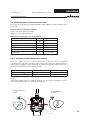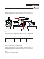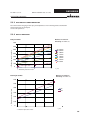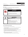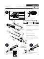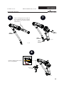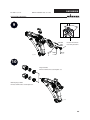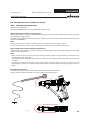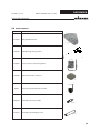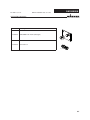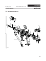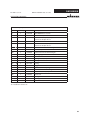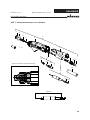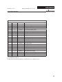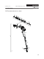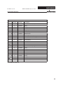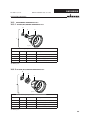
1
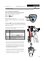
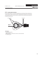
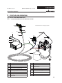
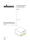
Translation of the original Operating manual GM 5000EA Edition 03/2012 Electrostatic Airspray gun for manual operation with flat or round jet nozzles 0102 c us II 2 G EEx 0.24 mJ (in submission) B_03229 EDITION 03/2012 ORDER NUMBER DOC 2319149 GM 5000EA OPERATING MANUAL Contents 1 1.1 1.2 ABOUT THESE INSTRUCTIONS Languages Warnings, notes and symbols in these instructions 6 6 6 2 2.1 2.1.1 2.1.2 2.1.3 2.2 2.2.1 2.2.2 2.2.3 2.2.4 2.2.5 2.2.6 2.3 2.4 2.5 2.5.1 2.5.2 2.5.2.1 2.5.3 2.6 GENERAL SAFETY INSTRUCTIONS Safety instructions for the operator Electrical equipment Personnel qualifications A safe work environment Safety instructions for staff Safe handling of WAGNER spray units Earth the unit Material hoses Cleaning Handling hazardous liquids, varnishes and paints Touching hot surfaces Correct use Safety-relevant information about discharges Use in an explosion hazard area Correct use Explosion protection identification CE Identification „X“ Explosion protection identification FM German regulations and guidelines 7 7 7 7 7 7 8 8 8 9 9 10 10 11 11 11 11 11 12 12 3 3.1 3.2 3.3 GUARANTEE AND CONFORMITY DECLARATIONS Important notes on product liability Guarantee claim CE-Conformity 13 13 13 14 4 4.1 4.1.1 4.2 4.3 4.4 4.4.1 4.4.2 4.5 4.5.1 4.5.2 4.5.3 DESCRIPTION Fields of application, using in accordance with the instructions Processable materials Scope of delivery Technical data Functional description Design of spray gun (standard variant) Functions of the spray gun Spraying process Air atomizing spray process - round jet Air atomizing spray process - flat jet The electrostatic effect 15 15 15 16 17 18 18 19 20 20 20 21 5 5.1 5.1.1 5.1.2 5.1.3 5.1.4 5.1.5 START-UP AND OPERATION Installation and connection Typical electrostatic air spraying system Ventilation of the spray booth Air supplies Paint supplies Earthing 22 22 22 23 24 24 25 3 EDITION 03/2012 ORDER NUMBER DOC 2319149 GM 5000EA OPERATING MANUAL Contents 5.2 5.2.1 5.3 5.3.1 5.3.2 5.3.3 5.3.4 5.4 5.4.1 5.4.2 5.5 5.5.1 5.5.2 5.5.3 5.5.4 Preparation of paints Viscosity conversion table Wagner electrostatic air spraying system Pressure settings for round jet nozzles Pressure settings for flat jet nozzles Electrostatic and atomization Output measured Start-up General rules for making adjustments to the spray gun Preparation for starting up Working Filling with working material Start-up for spraying Changing from Air-round jet to Air-flat jet Cleaning of the nozzle parts 27 27 28 28 29 30 30 31 31 31 33 33 34 35 35 6 6.1 6.2 6.3 6.4 6.5 6.6 6.6.1 6.6.2 6.6.3 6.6.4 MAINTENANCE Periodically checks Cleaning and decommissioning Dismantling of the spray gun Cleaning the parts after disassembly Assembling the spray gun Function test after assembly of the gun Checking the high-voltage Air tests Material pressure test Check spray pattern 36 36 36 38 41 42 46 46 47 47 48 7 TROUBLE SHOOTING AND SOLUTION 49 8 PRODUCT DISPOSAL 50 9 9.1 9.1.1 9.1.2 9.2 9.2.1 9.2.2 9.3 9.3.1 9.3.2 9.4 9.4.1 9.4.2 9.4.3 9.5 9.6 ACCESSORIES Valve seats, Air/ Valve tips, Air Valve seats Valve tips Round jet nozzles AR 5000 air caps AR 5000 nozzles Flat jet nozzles AF 5000 air caps AF 5000 nozzles Hoses and electrical cables Standard hose sets and components Hose sets for low impedance materials Gun cable and gun cable extensions Reduction fittings for high-pressure hoses Miscellaneous 50 50 50 50 51 51 51 51 51 52 53 53 54 55 55 56 4 EDITION 03/2012 ORDER NUMBER DOC 2319149 GM 5000EA OPERATING MANUAL Contents 10 10.1 10.2 10.2.1 10.2.2 10.3 10.3.1 10.3.2 SPARE PARTS How to order spare parts? GM 5000EA spare parts list GM 5000EA spare parts list- End piece GM 5000EA spare parts list - Handle Accessories spare parts lists AR 5000 (D8) nozzle spare parts list AR 5000 (D12) nozzle spare parts list 59 59 60 62 64 66 66 66 5 EDITION 03/2012 GM 5000EA ORDER NUMBER DOC 2319149 OPERATING MANUAL 1 ABOUT THESE INSTRUCTIONS 4HISOPERATINGMANUALCONTAINSINFORMATIONABOUTTHEOPERATIONREPAIRANDMAINTENANCE OFTHEUNIT !LWAYSFOLLOWTHESEINSTRUCTIONSWHENOPERATINGTHEUNIT 4HISEQUIPMENTCANBEDANGEROUSIFITISNOTOPERATEDINACCORDANCEWITHTHISMANUAL %LECTROSTATICSPRAYGUNSMAYBEOPERATEDONLYBYTRAINEDPERSONNEL #OMPLIANCEWITHTHESEINSTRUCTIONSCONSTITUTESANINTEGRALCOMPONENTOFTHEGUARANTEE AGREEMENT 1.1 LANGUAGES 4HISOPERATINGMANUALISAVAILABLEINTHEFOLLOWINGLANGUAGES ,ANGUAGE 0ART.O ,ANGUAGE 'ERMAN 2310480 %NGLISH &RENCH 2320149 $UTCH )TALIAN 2320150 3PANISH 1.2 0ART.O 2319149 2320151 WARNINGS, NOTES AND SYMBOLS IN THESE INSTRUCTIONS Warning instructions in this manual point out particular dangers to users and equipment and state measures for avoiding the hazard. These warning instructions fall into the following categories: DANGER Danger - imminent danger. Non-observance will result in death, serious injury and serious material damage. This line warns of the hazard! Possible consequences of failing to observe the warning instructions. The signal word points out the hazard level. SIHI_0100_GB Warning - possible danger. Non-observance can result in death, serious injury and serious material damage. The measures for preventing the hazard and its consequences. WARNING This line warns of the hazard! Possible consequences of failing to observe the warning instructions. The signal word points out the hazard level. SIHI_0103_GB The measures for preventing the hazard and its consequences. Caution - a possibly hazardous situation. Non-observance can result in minor injury. CAUTION This line warns of the hazard! Possible consequences of failing to observe the warning instructions. The signal word points out the hazard level. SIHI_0101_GB Caution - a possibly hazardous situation. Non-observance can cause material damage. The measures for preventing the hazard and its consequences. SIHI_0102_GB CAUTION This line warns of the hazard! Possible consequences of failing to observe the warning instructions. The signal word points out the hazard level. The measures for preventing the hazard and its consequences. Note - provide information on particular characteristics and how to proceed. 6 EDITION 03/2012 ORDER NUMBER DOC 2319149 GM 5000EA OPERATING MANUAL 2 GENERAL SAFETY INSTRUCTIONS 2.1 SAFETY INSTRUCTIONS FOR THE OPERATOR Keep these operating instructions to hand near the unit at all times. Always follow local regulations concerning occupational safety and accident prevention. 2.1.1 ELECTRICAL EQUIPMENT Electrical plant and unit To be provided in accordance with the local safety requirements with regard to the operating mode and ambient influences. May only be maintained by skilled electricians or under their supervision. Must be operated in accordance with the safety regulations and electrotechnical regulations. Must be repaired immediately in the event of problems. Must be put out of operation if they pose a hazard. Must be de-energized before work is commenced on active parts. Inform staff about planned work, observe electrical safety regulations. 2.1.2 PERSONNEL QUALIFICATIONS %NSURETHATTHEUNITISOPERATEDANDREPAIREDONLYBYTRAINEDPERSONS 2.1.3 A SAFE WORK ENVIRONMENT Make sure that the floor in the area where you are working is anti-static in accordance with EN 61340-4-1 (the resistance value may not exceed 100 MOhm). Ensure that all persons within the working area wear antistatic shoes. Footwear must comply with EN 20344. The measured insulation resistance may not exceed 100 MOhm. Ensure that during spraying, persons wear anti-static gloves so that they are earthed via the handle of the spray gun. If protective clothing is worn, including gloves, it has to comply with EN 1149-5. The measured insulation resistance may not exceed 100 MOhm. Paint mist extraction systems must be fitted on site according to the local regulations. Ensure that the following components of a safe working environment are available: – Material/air hoses adapted to the working pressure. – Personal safety equipment (breathing and skin protection). Ensure that there are no ignition sources such as naked flame, glowing wires or hot surfaces in the vicinity. Do not smoke. 2.2 SAFETY INSTRUCTIONS FOR STAFF Always follow the information in these instructions, particularly the general safety instructions and the warning instructions. Always follow local regulations concerning occupational safety and accident prevention. 7 EDITION 03/2012 ORDER NUMBER DOC 2319149 GM 5000EA OPERATING MANUAL 2.2.1 SAFE HANDLING OF WAGNER SPRAY UNITS The spray jet is under pressure and can cause dangerous injuries. Avoid injection of paint or cleaning agents: Never point the spray gun at people. Never reach into the spray jet. Before all work on the unit, in the event of work interruptions and functional faults: – Switch off the energy/compressed air supply. – Secure the spray gun against actuation. – Relieve the pressure from the spray gun and unit. – By functional faults: Identify and correct the problem, proceed as described in chapter „Trouble shooting“. In the event of skin injuries caused by paint or cleaning agents: Note down the paint or cleaning agent that you have been using. Consult a doctor immediately. Avoid danger of injury through recoil forces: Ensure that you have a firm footing when operating the spray gun. Only hold the spray gun briefly in any one position. 2.2.2 EARTH THE UNIT Depending on the high-voltage of the spray electrode and the flow rate at spray pressures can produce an electrostatic charge in the equipment. These can cause sparks and flames upon discharge. Ensure that the unit is always earthed. Earth the work pieces to be coated. Ensure that all persons inside the working area are earthed, e.g. that they are wearing derivable shoes. When spraying, wear derivable gloves to earth yourself via the spray gun handle. 2.2.3 MATERIAL HOSES Ensure that the hose material is chemically resistant to the sprayed materials. Ensure that the material hose is suitable for the pressure generated in the unit. Ensure that the following information is visible on the high pressure hose: – Manufacturer – Permissible operating overpressure – Date of manufacture. The electrical resistance of the complete high pressure hose must be less than 1 MOhm. 8 EDITION 03/2012 ORDER NUMBER DOC 2319149 GM 5000EA OPERATING MANUAL 2.2.4 CLEANING De-energize the unit electrically. Disconnect the pneumatic supply line. Relieve the pressure from the unit. Ensure that the flash point of the cleaning agent is at least 15K above the ambient temperature. Otherwise, the cleaning works shall be carried out at forced ventilated cleaning place. To clean, use only solvent-soaked cloths and brushes. The cleaning process mustn´t damage parts of the spray gun, it mustn´t be an abrasive procedure. Parts of spray gun mustn´t submerged or soaked into solvent. Non-ignitable cleaning liquids shall be preferred. A suitable solvent for cleaning the spray gun depends on the part of the gun and on the material that needs to be removed. It´s recommended to use only non-polar solvents to prevent a conductive residue on critical components. If it´s necessary to use polar solvents to clean the spray gun components, all residue must be removed by using a nonconductive non-polar solvent. All electrical components cannot be cleaned or soaked in any solvents. An explosive gas/air mixture forms in closed containers. When cleaning units with solvents, never spray into a closed container. For cleaning liquids only electrically leading containers may be used. The containers must be earthed. 2.2.5 HANDLING HAZARDOUS LIQUIDS, VARNISHES AND PAINTS When preparing or working with paint and when cleaning the unit, follow the working instructions of the manufacturer of the paints, solvents and cleaning agents being used. Take the specified protective measures, in particular wear safety goggles, protective clothing and gloves, as well as hand protection cream if necessary. Use a mask or breathing apparatus if necessary. For sufficient health and environmental safety: Operate the unit in a spray booth or on a spraying wall with the ventilation (extraction) switched on. Wear suitable protective clothing when working with hot materials. 9 EDITION 03/2012 ORDER NUMBER DOC 2319149 GM 5000EA OPERATING MANUAL 2.2.6 TOUCHING HOT SURFACES ➞ Touch hot surfaces only if you are wearing protective gloves. ➞ When operating the unit with a coating material with a temperature of > 43 °C; 109.4 °F: - Identify the unit with a warning label that says „Warning - hot surface“. Order No. 9998910 Information label 9998911 Safety label 2.3 CORRECT USE 7!'.%2ACCEPTSNOLIABILITYFORANYDAMAGEARISINGFROMINCORRECTUSE 5SETHEUNITONLYTOWORKWITHTHEMATERIALSRECOMMENDEDBY7!'.%2 /PERATETHEUNITONLYASANENTIREUNIT $ONOTDEACTIVATESAFETYEQUIPMENT 5SEONLY7!'.%2ORIGINALSPAREPARTSANDACCESSORIES 10 EDITION 03/2012 ORDER NUMBER DOC 2319149 GM 5000EA OPERATING MANUAL 2.4 SAFETY-RELEVANT INFORMATION ABOUT DISCHARGES The plastic parts of the spray gun are charged electrostatically by the high-voltage field of the spray pistol. Harmless discharges (brush discharges) are possible after contact with plastic parts. They are completely harmless for people. The corona discharge at the electrode end is visible during darkness at a distance of be between 4 and 10 mm; 0.15 and 0.4 inches, between the spray gun and spray object. 2.5 USE IN AN EXPLOSION HAZARD AREA In hazardous locations only approved explosion-proof electrical equipment is used. 2.5.1 CORRECT USE The GM 5000EA electrostatic hand spray gun is suitable for spraying liquid materials, particularly coating materials, using the air atomizing method. Coating materials containing solvents of Explosion Class II A may be used. The spray gun may only be used in combination with the VM 500 and VM 5000 control unit. 2.5.2 EXPLOSION PROTECTION IDENTIFICATION CE As defined in the Directive 94/9/EC (ATEX), the unit is suitable for use in areas where there is an explosion hazard. II 2G EEx 0.24mJ X 0102 SIRA 11 ATEX 5374X CE 0102 Communautés Européennes Notified body: PTB E European Standard Ex Explosion protected Ex Symbol for explosion protection 0.24mJ Max. firing power II Unit class II 2 Category 2 (Zone 1) G Ex-atmosphere gas SIRA 11 ATEX 5374X 2.5.2.1 Number of the type examination certificate IDENTIFICATION „X“ Max. surface temperature s Maximum surface temperature: s Maxi. Permissible material temperature: s Permissible ambient temperature: 85 °C; 185 °F 50 °C; 122 °F +0 to +40 °C; +32 to +104 °F Safety instructions 3AFEHANDLINGOF7!'.%2SPRAYUNITS -ECHANICALSPARKSCANFORMIFTHEUNITCOMESINTOCONTACTWITHMETAL )NANEXPLOSIVEATMOSPHERE $ONOTKNOCKORPUSHTHEUNITAGAINSTSTEELORRUSTYIRON $ONOTDROPTHEGUN 5SEONLYTOOLSTHATAREMADEOFAPERMITTEDMATERIAL 11 EDITION 03/2012 GM 5000EA ORDER NUMBER DOC 2319149 OPERATING MANUAL )GNITIONTEMPERATUREOFTHECOATINGMATERIAL %NSURETHATTHEIGNITIONTEMPERATUREOFTHECOATINGMATERIALISABOVETHEMAXIMUM SURFACETEMPERATURE 3URFACESPRAYINGELECTROSTATIC $ONOTSPRAYUNITPARTSWITHELECTROSTATICEGELECTROSTATICSPRAYGUN -EDIUMSUPPORTINGATOMIZING 4OATOMIZETHEMATERIALUSEONLYWEAKLYOXIDIZINGGASESEGAIR Cleaning If there are deposits on the surfaces, the unit may form electrostatic charges. Flames or sparks can form if there is a discharge. Remove deposits from the surfaces to maintain conductivity. Use only a damp cloth to clean the unit. 2.5.3 EXPLOSION PROTECTION IDENTIFICATION FM For Electrostatic Finishing Applications using Class I, Group D, Spray Material C US In accordance with 2316160 (the device is in submission) This device has been manufactured and tested according to the FM (Factory Mutual) standard „Class Number 7260“ (Approval Standard for Electrostatic Finishing Equipment) by FM. All tested combinations of devices including accessories are given in the FM Control Document with part number 2316160. 2.6 GERMAN REGULATIONS AND GUIDELINES a) b) c) d) e) f) BGV A3 BGR 500 BGR 500 BGR 104 TRBS 2153 BGR 180 g) h) j) j) ZH 1/406 BGI 740 BGI 764 Betr.Sich.V. Electrical units and equipment Part 2, Chap. 2.36 Working with liquid ejection devices Part 2, Chap. 2.29 Using coating materials Explosion protection rules Avoiding ignition risks Setting up for cleaning with solvents for cleaning workpieces with solvents Guidelines for liquid ejection devices Painting rooms and equipment Electrostatic coating Plant Safety Ordinance Note: All titles can be ordered from Heymanns Publishing House in Cologne, or they are to be found in the Internet. 12 EDITION 03/2012 ORDER NUMBER DOC 2319149 GM 5000EA OPERATING MANUAL 3 GUARANTEE AND CONFORMITY DECLARATIONS 3.1 IMPORTANT NOTES ON PRODUCT LIABILITY As a result of an EC regulation, effective as from January 1, 1990, the manufacturer shall only be liable for his product if all parts come from him or are approved by him, and if the devices are properly fitted , operated and maintained. If other makes of accessory and spare parts are used, the manufacturer‘s liability could be fully or partially null and void. The usage of original WAGNER accessories and spare parts guarantees that all safety regulations are observed. 3.2 GUARANTEE CLAIM Full guarantee is provided for this device: We will at our discretion repair or replace free of charge all parts which within 24 months in single-shift, 12 months in 2-shift or 6 months in 3-shift operation from date of receipt by the Purchaser are found to be wholly or substantially unusable due to causes prior to the sale, in particular faulty design, defective materials or poor workmanship. The type of guarantee provided is such that the device or individual components of the device are either replaced or repaired as we think fit. The resulting costs, in particular shipping charges, road tolls, labour and material costs will be borne by us except where these costs are increased due to the subsequent shipment of the unit to a location other than the address of the purchaser. We do not provide guarantee for damage that has been caused or contributed to for the following reasons: Unsuitable or improper use, faulty installation or commissioning by the purchaser or a third party, normal wear, negligent handling, defective maintenance, unsuitable coating products, substitute materials and the action of chemical, electro chemical or electrical agents, except when the damage is attributable to us. Abrasive coating products such as red lead, emulsions, glazes, liquid abrasives, zinc dust paints and similar reduce the service life of valves, packings, spray guns, tips, cylinders, pistons etc. Signs of wear and tear due to such causes are not covered by this guarantee. Components that have not been manufactured by WAGNER are subject to the original guarantee of the manufacturer. Replacement of a component does not extend the period of guarantee of the device. The unit should be inspected immediately upon receipt. To avoid losing the guarantee, we or the supplier company are to be informed in writing about obvious faults within 14 days upon receipt of the device. We reserve the right to have the guarantee compliance met by a contracting company. The services provided by this guarantee depend on evidence being provided in the form of an invoice or delivery note. If an examination discovers that no guarantee claim exists, the costs of repairs are charged to the purchaser. It is clearly stipulated that this guarantee claim does not represent any constraint to statutory regulations or regulations agreed contractually in our general terms and conditions. J. Wagner AG 13 EDITION 03/2012 GM 5000EA ORDER NUMBER DOC 2319149 OPERATING MANUAL 3.3 CE-CONFORMITY EC declaration of conformity as defined by Atex-directive 94/9/EC. Herewith we declare that the supplied version of Electrostatic hand spraying system VM 500 VM 5000 GM 5000EA GM5000EAC Complies with the following guidelines: 94/9/EG 2004/108/EG 2006/42/EG 2002/95/EG 2002/96/EG Applied standards, in particular: DIN EN 50050:2007 DIN EN 61000-6-2:2006 DIN EN ISO 12100:2011 DIN EN 1953:2010 DIN EN 61000-6-4:2011 DIN EN 60079-0: 2010 DIN EN 60079-15: 2011 DIN EN 60204-1: 2007 Applied national technical standards and specifications, in particular: BGI 764 EC type examination certificate: SIRA 11 ATEX 5374X issued by SIRA Certification, CH4 9JN, Chester, England, notified body no. 0518 Identification: Control unit: II (2) G 0102 SIRA 11 ATEX 5374X II 3 G Ex nR IIC T4 Gc Spray gun: II 2 G EEx 0.24mJ 0102 SIRA 11 ATEX 5374X CE Certificate of Conformity The certificate is enclosed with this product. The certificate of conformity can be reordered from your WAGNER representative, quoting the product and serial number. Part number: 2310487 14 EDITION 03/2012 ORDER NUMBER DOC 2319149 GM 5000EA OPERATING MANUAL 4 DESCRIPTION 4.1 FIELDS OF APPLICATION, USING IN ACCORDANCE WITH THE INSTRUCTIONS The electrostatic spray gun can only be used with the VM 5000 or VM 500 control units. 4.1.1 PROCESSABLE MATERIALS ➞ With the GM 5000EA gun, paints can be applied which contain solvent of explosion class II A. ➞ The spray gun basic version is suitable for processing of sprayed substances with an electrical resistance of > 150 k (according to the WAGNER scale). Equipped with a special material hose for low impedance sprayed substances (available as accessory) you can also sprayed substances with an electrical conductivity > 50 k (according to the WAGNER scale) process successfully. ➞ The application effectiveness is always dependant on the composition of the paint being used, e.g. pigments or resin. Conversion of the resistance of paint There are paint resistance measuring devices on the market that do not measure directly the specific resistance of paint. Multiplying the result of measurement with the device-specific cell constant (K), we obtain the resistivity value of the material. Example: The Wagner paint resistance measuring device is the cell constant K =123. Measured value according to the WAGNER scale R = 500 k Specific resistance (RS) RS = R x K = 500 k x 123 = 61.5 M.cm Note: With sprayed substances and those with too low electrical resistance the electrostatic effect will not have any effect, i.e., there will be no „wrap around“ noticeable at the spray object. The relationship between the values of the high-voltage (kV) and the current (µA), shown on the VM 5000 control unit and/or on the spray gun, denotes the charging capacity of a spray material. High kV value, low µA value = ok Low kV-value, high µA-value = Excessive conductivity of the paint -> no wrap-around In the event of application problems, contact your WAGNER branch and the paint manufacturer. 15 EDITION 03/2012 ORDER NUMBER DOC 2319149 GM 5000EA OPERATING MANUAL 4.2 SCOPE OF DELIVERY Quantity Part No. Description 1 2309870 GM 5000EA spray gun Without control unit, material and air hose, electrical cable, air cap and nozzle. Each gun includes as standard equipment: Part No. Description 1 2309368 Assembly tool valve needle 1 2325263 Assembly tool clamping screw 1 2319653 Glove against ink mist precipitation 1 2310487 CE-Conformity - 2310480 Operating manual German 1 see 1.1 Operating manual in the local language The spray gun basic version can be set according to requirement and the desired accessories with the help of the spray gun configuration. The delivery note shows the exact scope of delivery. 16 EDITION 03/2012 GM 5000EA ORDER NUMBER DOC 2319149 OPERATING MANUAL 4.3 TECHNICAL DATA Max. air pressure 0.8 MPa; 8 bar; 116 psi Max. material pressure 0.8 MPa; 8 bar; 116 psi Paint connection G 1/4“ A Air connection G 1/4“ A Input voltage max. 20 Vpp Input current max. 1.0 A AC Output voltage max. 80 kV DC Output current max. 100 µA DC Polarity negative Weight (without hose set) 630 g (incl. union nut, nozzle and air cap) Working temperature range Material temperature Sound level at 0.3 MPa; 3 bar; 43.5 psi air pressure and 0.3 MPa; 3 bar; 43.5 psi material pressure 0 °C to 40 °C; 32 °F to 104 °F 50 °C; 122 °F 78 dB(A) * * A rated sound pressure level measured at 1 m distance according to DIN EN 14462: 2005. A C Measurements B GM 5000EA F with flat jet nozzle mm inches A 261 10.28 B 46 1.81 C 245 9.65 B_03231 A C B GM 5000EA R with round jet nozzle mm inches A 261 10.28 B 46 1.81 C 245 9.65 B_03230 17 EDITION 03/2012 GM 5000EA ORDER NUMBER DOC 2319149 OPERATING MANUAL 4.4 FUNCTIONAL DESCRIPTION 4.4.1 DESIGN OF SPRAY GUN (STANDARD VARIANT) Note: The nozzle parts (item 5; 7; 14 and 20) do not belong to the basic equipment of the spray gun. The different versions can be found in Chapter 9 „Accessories“. 9 8 1 2 22 3 15 21 7 4 16 10 14 6 17 19 18 11 5 20 12 B _03232 6 Item Description Item Description 1 Suspension hook 10 Handle 2 Display (spray current and recipe) 11 Adjusting screw (stop) 3 Display (standby and fault) 12 Trigger 4 Operating button (standby and recipe change) 14 Nozzle AR 5000 (Accessories, chapter 9) 15 Lock plug 5 Air cap Air (Accessories, chapter 9) 16 Air adjustment 6 Union nut 17 Electrical cable connection 7 Fan spray nozzle AF 5000 x.x (Accessories, chapter 9) 18 Atomizing air connection 8 End-piece 19 Material connection 9 Cover 20 Air cap AR 5000 (Accessories, chapter 9) 21 Type plate left 22 Type plate right Note: The gun type (T) on the type plate (21) and the serial number (S) on the underside of the handle. S B_03558 18 EDITION 03/2012 GM 5000EA ORDER NUMBER DOC 2319149 OPERATING MANUAL 4.4.2 FUNCTIONS OF THE SPRAY GUN When the spray gun is connected to the control unit and the control unit is switched on, the pre-defined recipe (R1, R2 or R3) is shown on the gun display (2) as follows. Recipe 1 -> ●❍❍❍❍ R1 Recipe 2 -> ●●●❍❍ R2 2 Recipe 3 -> ●●●●● R3 Recipe change R1 -> R2 -> R3 -> R1 Press the operating button (4) and hold the button pressed of at least 2 seconds, then it is advanced by 1 recipe. R2 R1 R3 3 4 Display (2) -> ●●❍❍❍ = recipe values changed temporarily: The stored recipe values of the previously selected recipe number are re-loaded from memory by pressing the operating button (4) for 2 seconds. B_03182 The trigger can be used to activate, one after the other, the various functions of the spray gun. Distance Description 1 Atomizing air open. 2 Atomizing air open and electrostatically (HV) activated. -> Display (2) for „spray current“ on the spray gun ●❍❍❍❍ to ●●●●● activated. 3 Atomizing air open, electrostatically (HV) activated and material valve open. 4 Max way of trigger. 1 2 3 4 • An increase in the tension needed to pull the trigger back will be felt at the position where the material valve opens. • For spraying without high-voltage, the high-voltage can be switched off using the operating button (4). Press the operating button (4) briefly: High-voltage is switched off. The standby display (3) illuminates. R1 R2 • In the event of a malfunction the spray gun switches to R3 16 „standby“ operating mode and the display (3) illuminates. • The width of the spray jet can be adjusted using the air adjustment (16) (only for flat-jet method). B_03183 19 EDITION 03/2012 GM 5000EA ORDER NUMBER DOC 2319149 OPERATING MANUAL 4.5 SPRAYING PROCESS 4.5.1 AIR ATOMIZING SPRAY PROCESS - ROUND JET In this process, the material (paint) is fed to the nozzle with low pressure (0.05-0.2 MPa; 0.5-2 bar; 7-29 psi). The atomizing air at approx. 0.25-0.4 MPa; 2.5-4 bar; 36-58 psi produces a soft jet, which largely eliminates the problem of overlapping boundaries. There are various nozzles and air caps available as accessories for the respective spraying material and the output amounts. Union nut Spray pattern Atomizing air Spray material B_03446 Advantages • Low coating thickness • Perfect finish • Uniform coating thickness 4.5.2 AIR ATOMIZING SPRAY PROCESS - FLAT JET In this process, the material (paint) is fed to the nozzle with low pressure (0.05-0.2 MPa; 0.5-2 bar; 7-29 psi). The atomizing air at approx. 0.25-0.4 MPa; 2.5-4 bar; 36-58 psi produces a soft jet, which largely eliminates the problem of overlapping boundaries. The spray jet can be changed using the shaping air. There are various nozzles and air caps available as accessories for the respective spraying material and the output amounts. Air cap Spray pattern Shaping air Spray material Spray angle Atomizing air B_00180 Advantages • Large range of adjustment of the jet spray • Uniform coating thickness • Low coating thickness • Perfect finish 20 EDITION 03/2012 ORDER NUMBER DOC 2319149 GM 5000EA OPERATING MANUAL 4.5.3 THE ELECTROSTATIC EFFECT The spray gun produces an electrostatic field by means of the high-voltage electrode. As a result, the particles of paint, which have been atomized by the spray gun, are carried to the earthed object by kinetic and electrostatic energy where they adhere, finely distributed, to the object being sprayed. Paint particle Electrode Grounded object "? Advantages Very efficient spraying Little over spray Coating of entire circumferences due to an electrostatic field Less working time • • • • 21 EDITION 03/2012 GM 5000EA ORDER NUMBER DOC 2319149 OPERATING MANUAL 5 START-UP AND OPERATION 5.1 INSTALLATION AND CONNECTION 5.1.1 TYPICAL ELECTROSTATIC AIR SPRAYING SYSTEM LFL 12 Electrostatic air spraying system 7 6 10 8 11 15 14 PZL 2 4 3 5 PMAT 8 6 9 10 1 13 B_03233 Item Description Item Description 1 Pressure tank 9 VM 5000 control unit 2 Stop valve 10 Material hose 3 Air pressure regulator tank 11 Compressed air main 4 Air pressure regulator with air filter 12 GM 5000EAR spray gun 5 Earthing cable 13 Container for return flow 6 Air hose 14 Protective hose 7 Air adjustment 15 Mains cable 8 Gun cable 22 EDITION 03/2012 ORDER NUMBER DOC 2319149 GM 5000EA OPERATING MANUAL The GM 5000EA spray gun must be used a part of an electrostatic spraying system (spray-pack). The spraying system shown in the figure B_03233 is only one example of an electrostatic air spraying system. Contact your Wagner distributor for assistance in designing a system to meet your needs. The operating instructions and the safety regulations for the additional system compo-nents used must be read before starting-up. WARNING Incorrect installation/operation! Risk of injury and damage to equipment When putting into operation and for all work, read and follow the operating instructions and safety regulations for the additionally required system components. SIHI_0050_GB 5.1.2 VENTILATION OF THE SPRAY BOOTH The electrostatic hand spraying equipment is for use only in spray areas which correspond with standard EN 12215. The electrostatic hand spraying equipment has to be locked to the technical ventilation so that the coating material supply and the high-voltage are not effective as long as the technical ventilation is not operated with the minimum exhaust air volume flow or a larger exhaust air volume flow. Ensure that the excess coating material (overspray) will be collected up safely. WARNING Toxic and/or flammable vapor mixtures! Risk of poisoning and burns Operate the unit in a spraying booth approved for the working materials. -or Operate the unit on an appropriate spraying wall with the ventilation (extraction) switched on. Observe national and local regulations for the outgoing air speed. SIHI_0028_GB 23 EDITION 03/2012 ORDER NUMBER DOC 2319149 GM 5000EA OPERATING MANUAL 5.1.3 AIR SUPPLIES The use of an air filter with the air regulator (4) ensures that only dry, clean atomizing air gets into the spray gun. Dirt and moisture in the atomizing air reduce the spraying quality and the appearance of the finished piece. 5.1.4 PAINT SUPPLIES CAUTION Impurities in the spraying system! Spray gun blockage, materials harden in the spraying system Flush the spray gun and paint supply with a suitable cleaning agent. SIHI_0001_GB DANGER Bursting hose, bursting threaded joints! Danger to life from injection of material Ensure that the hose material is chemically resistant. Ensure that the spray gun, threaded joints and material hose between the unit and the spray gun is suitable for the pressure generated in the unit. Ensure that the following information can be seen on the high pressure hose: - Manufacturer - Permissible operating pressure - Date of manufacture. SIHI_0029_GB 24 EDITION 03/2012 ORDER NUMBER DOC 2319149 GM 5000EA OPERATING MANUAL 5.1.5 EARTHING Perfect earthing of all conductive parts such as floors, walls, roofs, is important for optimum coating and safety. Barriers, work pieces, transport devices, coating material container, automatic movement system or construction parts in the spray area must be connected to the earthing system, with exception of the high-voltage parts during normal operation. Part of the booth must be grounded in accordance with EN 12215. WARNING Discharge of electrostatically charged components in atmospheres containing solvents! Explosion hazard from electrostatic sparks or flames Earth all unit components. Earth the workpieces being painted. SIHI_0027_GB WARNING Heavy paint mist if earthing is insufficient! Risk of poisoning Insufficient paint application quality Earth all unit components. Earth the workpieces being painted. SIHI_0003_GB The imperfect earthing of a work piece will result in: • Very poor wrap-around. • Uneven coating thickness. • Back spraying to the spray gun, i.e. contamination. The prerequisites for perfect earthing and coating are: • Clean work piece suspension. • Earthing of spray booth, conveyor system and suspension on the building side in accordance with the operating instruction or the manufacturer‘s information. • Earthing of all conductive parts within the working area. • The earthing resistance of the work piece may not exceed 1 M (Mega Ohm). Note: Resistance to earth measured at 500 V or 1000 V. • Connect the control unit to the mains system earth. 25 EDITION 03/2012 GM 5000EA ORDER NUMBER DOC 2319149 OPERATING MANUAL Earthing scheme (example) Control unit Conveyor Note for the sprayer The work shoes and if used the gloves must be derivable. Work piece Earthing cable Pump or pressure tank Paint container or container for return flow R max < 1 MΩ Spraying stand B_03234 Floor, derivable Minimum cable cross-section Control unit 4 mm² (AWG 12) Pump 4 mm² (AWG 12) Paint container 4 mm² (AWG 12) Conveyor 16 mm² (AWG 6) Booth 16 mm² (AWG 6) Spraying stand 16 mm² (AWG 6) 26 EDITION 03/2012 GM 5000EA ORDER NUMBER DOC 2319149 OPERATING MANUAL 5.2 PREPARATION OF PAINTS The viscosity of the paints is of great importance. The best spraying results are obtained with values between 15 and 30 DIN-s (measured in immersion flow cup DIN 4 mm; 0.16 inches). In the case of application problems contact the paint producer. 5.2.1 VISCOSITY CONVERSION TABLE milli Pascal x Sec mPas Centipoise 10 10 15 Poise DIN Cup Ford Cup 4 Zahn 2 0.1 5 16 15 0.15 8 17 20 20 0.2 10 18 25 25 0.25 14 12 19 30 30 0.3 15 14 20 40 40 0.4 17 18 22 50 50 0.5 19 22 24 60 60 0.6 21 26 27 70 70 0.7 23 28 30 80 80 0.8 25 31 34 90 90 0.9 28 32 37 4 mm ; 0.16 inch 100 100 1 30 34 41 120 120 1.2 33 41 49 140 140 1.4 37 45 58 160 160 1.6 43 50 66 180 180 1.8 46 54 74 200 200 2 49 58 82 220 220 2.2 52 62 240 240 2.4 56 65 260 260 2.6 62 68 280 280 2.8 65 70 300 300 3 70 74 320 320 3.2 340 340 3.4 360 360 3.6 380 380 3.8 400 400 4 80 90 27 EDITION 03/2012 GM 5000EA ORDER NUMBER DOC 2319149 OPERATING MANUAL 5.3 WAGNER ELECTROSTATIC AIR SPRAYING SYSTEM The nozzle range (chapter 9), provided by Wagner, allows optimum coating results for each application. General criteria for selection of nozzles: Flat jet -> for parts with large surfaces Round jet -> for small delicate parts Influences on the jet spray - the spray pattern: Description Modification Material pressure PMat + or - Atomizing air pressure PZL + or - Air adjustment LFL from open to closing Stop screw material valve AMV from open to closing Nozzle sizes DS Material flow volume Electrostatic ES + or - or off 5.3.1 PRESSURE SETTINGS FOR ROUND JET NOZZLES There are 2 nozzle sizes, D8 and D12 available. The air cap and nozzle are adjusted according to size each other and may not be used reversed. During the calibration of the material pressure (PMAT) and the atomizing air pressure (PZL) the air control lever shown in the figure B_03266 must be in central position. Pressure setting D8 nozzle (small) D12 nozzle (large) Material pressure (PMAT ) 0.8 bar to 1.2 bar 0.8 bar to 1.6 bar Atomizing air pressure (PZL) 2.0 bar to 2.3 bar 2.3 bar to 3.0 bar Note: In the table, default values are included. Depending on the material, conditions and the desired result different values are possible or necessary. Air adjustment (LFL) closed Air adjustment (LFL) opened 28 B_03266 EDITION 03/2012 GM 5000EA ORDER NUMBER DOC 2319149 OPERATING MANUAL By turning the adjusting screw (AMV ) side of the gun, the outlet cross-section can be adjusted on the material valve. By reducing of this cross-section under the same pressure settings you might create a further refinement of the atomisation, i.e. turning the adjustment screw up. Spraying direction Rotate up Stop (AMV ) to front Smaller cross-section Stop (AMV ) to back Greater cross-section B_03267 Rotate down 5.3.2 PRESSURE SETTINGS FOR FLAT JET NOZZLES There are 8 flat jet nozzle sizes from 0.6 to 2.0 available. There are 3 air cap types. Each air cap can be used in combination with 2 or 3 nozzles sizes. Only matching nozzle components may be used. During the calibration of the material pressure (PMAT ) and the atomizing air pressure (PZL) the air control lever shown in the figure B_03266 must be in central position. These presettings are based on a paint viscosity of 22 DIN 4 sec. Pressure settings Air cap 0.4-0.8 Air cap 1.0-1.4 Air cap 1.6-2.0 Material pressure (PMAT ) 0.5 bar to 1.0 bar 1.0 bar to 2.0 bar 1.0 bar to 3.0 bar Atomizing air pressure (PZL) 1.0 bar to 2.5 bar 1.5 bar to 2.5 bar 1.5 bar to 3.0 bar Note: In the table, default values are included. Depending on the material, conditions and the desired result different values are possible or necessary. By turning the adjusting screw (AMV ) side of the gun, the outlet cross-section can be adjusted on the material valve. By reducing of this cross-section under the same pressure settings you might create a further refinement of the atomisation, i.e. turning the adjustment screw up. Note: In this setting the spray pattern is reduced. 29 EDITION 03/2012 GM 5000EA ORDER NUMBER DOC 2319149 OPERATING MANUAL 5.3.3 ELECTROSTATIC AND ATOMIZATION The electrostatic charging of the spray cloud produces a more homogeneous distribution of paint particles on the object. See also Chapter 4.5.3. 5.3.4 OUTPUT MEASURED Flat jet nozzles Device: GM 5000EAF Viscosity: 22 DIN 4 sec. 700 600 ø 0.6mm ø 0.8mm ø 1.0mm ø 1.2mm ø 1.4mm ø 1.6mm ø 1.8mm ø 2.0mm -> Output amounts in g/min 500 400 300 200 100 0 1 2 -> Material pressure in bar 3 B_03455 Round jet nozzles Device: GM 5000EAR Viscosity: 22 DIN 4 sec. 600 500 -> Output amounts in g/min 400 D8 D12 300 200 100 0 1 -> Material pressure in bar 2 3 B_03456 30 EDITION 03/2012 ORDER NUMBER DOC 2319149 GM 5000EA OPERATING MANUAL 5.4 START-UP 5.4.1 GENERAL RULES FOR MAKING ADJUSTMENTS TO THE SPRAY GUN ➞ Observe safety instructions in Chapter 2. DANGER High voltage field! Danger to life from malfunctioning heart pacemakers Ensure that persons with heart pacemakers: Do not work with the electrostatic spray gun. Remain outside the area of the electrostatic spray gun/workpiece. SIHI_0049_GB WARNING Unintentional putting into operation! Risk of injury Before all work on the unit, in the event of work interruptions and functional faults: Switch off the energy/compressed air supply. Relieve the pressure from the spray gun and unit. Secure the spray gun against actuation. By functional faults: Identify and correct the problem, proceed as described in chap „Trouble shooting“. SIHI_0065_GB 5.4.2 PREPARATION FOR STARTING UP The following points should be noted before starting up: ➞ For earthing see paragraph 5.1.5; make sure that all other conductive parts within the work area are earthed. ➞ Connect the material hose to spray gun and material pump or pressure tank. ➞ Check that all material-conveying connections are correctly connected. ➞ Connect air hose to spray gun and to oil-free, dry air, approx. 0.25 MPa; 2.5 bar; 36 psi. Compressed air quality class 3.5.2 according to ISO 8573.1. ➞ Check that all air-conveying connections are correctly connected. ➞ Connect the electric cable to the spray gun and to the VM 5000 or VM 500 control unit. ➞ Visually check the permissible pressures for all the system components. ➞ When using a Wagner pneumatic pump: Check the level of the release agent and if necessary fill the release agent up. 31 EDITION 03/2012 GM 5000EA ORDER NUMBER DOC 2319149 OPERATING MANUAL ➞ Provide material container, containers for detergent and an empty container for return. ➞ Connect the system to the air and power supply. ➞ A basic flushing of system must be carried out for initial start up. Make sure, that no nozzle is inserted into the gun. WARNING Sparks form when the plug is removed! Explosion hazard When using the spray gun in explosion hazard areas: The cable connection may neither be separated nor put together in this area. Cover sleeve plus warning sign have to be secured over the screw on the connector. SIHI_0139_ENG Attention: gun cable to control unit Cover sleeve with warning sign have to be secured over the screw (84) on the connector. 84 GM 5000E gun cable B_03691 Attention: guns with electrical extension cable Cover sleeves with warning signs have to be secured over the screws (84) on the connectors. Extension cable to the control unit GM 5000E gun cable 84 84 B_03690 32 EDITION 03/2012 GM 5000EA ORDER NUMBER DOC 2319149 OPERATING MANUAL LFL 12 7 6 10 8 11 15 14 PZL 2 4 3 5 PMAT 8 6 9 10 1 13 B_03233 5.5 WORKING 5.5.1 FILLING WITH WORKING MATERIAL 1. Provide an empty container for return (13). See image B_03233. 2. Put the container with work material into the pressure tank (1) and close the pressure tank. 3. Open the stop valve (2). 4. Adjust approx. 0.05 to 0.15 MPa; 0.5 to 1.5 bar; 7 to 22 psi on the pressure regulator (3). 5. Point the gun, without nozzle, into container (13) and open it. 6. Close stop valve (2) as soon as pure working material without any air inclusions starts coming from the gun. 7. Close the spray gun if the pressure tank is depressurised. 8. Dispose of the contents of the container (13) according to the local regulations. 33 EDITION 03/2012 GM 5000EA ORDER NUMBER DOC 2319149 OPERATING MANUAL 5.5.2 START-UP FOR SPRAYING 1. 2. 3. 4. 5. 6. Insert the desired nozzle into the gun. Open the stop valve (2). Turn on the control unit (9). Set the material supply to operating pressure PMAT. Spray on a test object (pull trigger). Adjust the spray pressure at the paint pump and/or pressure tank (1) according to the nozzle and object being sprayed. 7. Set air adjustment at the back of the gun to the center position and now open atomizing air (4) and adjust optimally according to the nozzle and object being sprayed. For round-jet method: 8. By turning at the air adjustment or at the stop screw on the side of the gun, the jet of the atomizing air is also influenced. Note The size of the air cap must match with the nozzle size. For flat-jet method: 9. Change the width of the spray jet by turning the air adjustment back to the spray gun or by appropriate selection of the nozzle. Notes A change in the material quantity is achieved by: - changing the material pressure or - use a different nozzle size (see accessories). Completely opened air adjustment B_03261 Closed air adjustment 34 EDITION 03/2012 ORDER NUMBER DOC 2319149 GM 5000EA OPERATING MANUAL 5.5.3 CHANGING FROM AIR-ROUND JET TO AIR-FLAT JET #!54)/. $EFECTIVEELECTRODE -ATERIALDAMAGEDUETOFUNCTIONALFAULTS $ONOTDAMAGETHEELECTRODE 3)()??'" 1. 2. 3. 4. 5. 6. 7. 8. 9. Switch off the control unit. Relieve spray gun and unit pressure. Replace paint with cleaning solvent. Set material pressure. Switch off the atomizing air. Flush the spray gun out thoroughly. Relieve the material pressure on the spray gun and the devise! Unscrew nozzle nut (2) by hand. Remove AR 5000 air cap (3). Unscrew and remove AR 5000 nozzle (4) by hand. Clean the spray gun front page with dampened cloth carefully. Pay attention to the electrode (1). Use the protection cap for the valve needle (8). 10. Screw in and tighten slightly AF 5000 flat jet nozzle (6) by hand. 11. Put on the AF 5000 air cap (5). Screw the union nut (2) onto the spray gun body. 12. Set the desired flat jet level with the air cap horns (7) and then tighten slightly the union nut by hand. 3 4 2 7 1 2 5 6 8 5.5.4 CLEANING OF THE NOZZLE PARTS The nozzle parts (2; 3; 4; 5 and 6) may only be immersed into a cleaning solvent, recommended by the manufacturer and must be immediately removed again. They may not be loaded for a long time in cleaning solvent. Clean these parts with a brush and dry them with a cloth or a blow gun. B_03268 35 EDITION 03/2012 GM 5000EA ORDER NUMBER DOC 2319149 OPERATING MANUAL 6 MAINTENANCE ➞ Observe safety instructions in Chapter 2. 6.1 PERIODICALLY CHECKS For the safe operation of electrostatic manual coating systems for flammable liquid spraying materials are intervals for periodically inspections defined as follows: Inspection point Inspection interval Remarks Gun cleaning, flushing daily Chapter 2.2.4; chapter 6.1 Earthing measures weekly Chapter 2.2.2; chapter 5.1.5 Inspection for damage weekly Chapter 6.2; 6.3; 6.4 and 6.5 Locking of the technical ventilation with the electrostatic manual coating system yearly Chapter 5.1.2 The above recommended intervals are maximum values and may be modified from operator depending on the local and operational conditions and contamination. Damaged devices must be taken out of service immediately and repaired. 6.2 CLEANING AND DECOMMISSIONING The spray gun and the unit must be cleaned every day. Only use the cleaning solvent recommended by the paint manufacturer. CAUTION Cleaning agent in the air duct! Functional faults caused by swollen seals Never immerse the spray gun in cleaning agent. SIHI_0066_GB WARNING Incorrect maintenance/repair! Risk of injury and damage to the equipment Repairs and part replacement may only be carried out by specially trained staff or a WAGNER service center. Before all work on the unit and in the event of work interruptions: - Switch off the energy/compressed air supply. - Relieve the pressure from the spray gun and unit. - Secure the spray gun against actuation. Observe the operating instructions when carrying out all work. SIHI_0141_GB 36 EDITION 03/2012 ORDER NUMBER DOC 2319149 GM 5000EA OPERATING MANUAL DANGER Exploding gas/ air mixture! Danger to life from flying parts and burns Never spray into a closed container. Earth the container. SIHI_0008_GB 1. Switch off control unit. 2. Ensure that the material pressure is relieved and shut off the atomizing air supply to the gun. 3. Connect the detergent supply. 4. Set material pressure. 5. Actuate the trigger guard. Flush the gun through thoroughly. 6. Relieve the pressure of gun and unit! 7. Remove nozzle and clean separately. 8. Clean the spray gun body with a cleaning agent recommended by the manufacturer and dry with a cloth or blow gun. CAUTION Cleaning agent in the air duct! Functional faults caused by swollen seals Discharge current to ground -> no high voltage Always point the spray gun down when cleaning. Ensure that neither paint nor cleaning agent enters the air duct. When taking a break from work or when stored for a longer period, the spray gun has to be positioned correctly with the attachment pointing downwards. SIHI_0145_GB B_03447 37 EDITION 03/2012 GM 5000EA ORDER NUMBER DOC 2319149 OPERATING MANUAL 6.3 DISMANTLING OF THE SPRAY GUN 1 SW3 SW12 SW12 B_03246 2 Torx 25 3 SW3 SW19 B_03247 SW19 38 EDITION 03/2012 GM 5000EA ORDER NUMBER DOC 2319149 OPERATING MANUAL 4 Carefully release the cascade without pliers. SW19 SW19 5 Assembly tool for needle valve. Part No. 2309368 SW11 B_03248 Note: Loosen valve tip Air by hand using an assembly tool. Use socket or ring spanner (no wrench). 6 B_03449 39 EDITION 03/2012 GM 5000EA ORDER NUMBER DOC 2319149 OPERATING MANUAL ø 3.0 7 1. Remove pressure spring (4). 2. Loosen clamping screw (1) completely with assembly tool (5). 3. Unscrew the complete package (3) via the complete valve rod unit (2, 6 and 7) or pull out the valve rod unit and unscrew it using an Allen key SW5. 4. If the loosened package (3) in the hole jammed, emit from the front (see upper image). 5 4 1 SW5 SW6 3 B_03198 2 6 7 SW2 9 8 1. Undo the oval head screw (1). 2. Pull the air valve out off the hole. SW8 Torx 20 Removing air valve: Unscrew and remove sealing 1 nut SW8. Hold the piston rear (2) and unscrew piston front SW5. SW9 2 SW5 SW14 B_03250 40 EDITION 03/2012 ORDER NUMBER DOC 2319149 GM 5000EA OPERATING MANUAL 6.4 CLEANING THE PARTS AFTER DISASSEMBLY ATTENTION Please note: ➞ All reusable parts (except for the parts that conduct the high-voltage such as cascade, end piece, plug compl. etc.) should be cleaned thoroughly using a suitable cleaning agent. ➞ The end piece, plug compl. and the handle inside must be clean and dry after cleaning. Care should be taken that these parts remain free of solvents, grease or sweat from the hands (salt water). ➞ Only spare parts are used which have undergone an EC type examination and are subject to a quality assessment (production monitoring) according to Directive 94/9/EC. ➞ Spare parts may have safety-relevant properties. ➞ Defective parts, O-rings and seal sets must always be re-placed. WARNING Incompatibility of cleaning agent and working medium! Risk of explosion and danger of poisoning by toxic gasses Check the compatibility of cleaning agent and working medium in accordance with safety data sheets. SIHI_0060_GB In chapter 10 can be found part numbers for gun spare parts as well as for wearing parts such as seals. 41 EDITION 03/2012 GM 5000EA ORDER NUMBER DOC 2319149 OPERATING MANUAL 6.5 ASSEMBLING THE SPRAY GUN 2 1 3 SW8 SW5 2 2 SW9 Torx 20 2 Ensure the correct insertion position! 1 B_03448 Ensure the correct insertion position! Mounting materials: B_03251 4 SW14 3 Nm Item Part No. Description 1 9992590 Loctite 222 2 9992698 Vaseline white PHHV II 3 9992831 Loctite 542 4 9992511 Loctite 243 42 EDITION 03/2012 GM 5000EA ORDER NUMBER DOC 2319149 OPERATING MANUAL Insertion position compl. package 3 SW2 1Nm X Valve rod unit Length adjusting measure X = 122 ± 0.1 2 SW5 Push together the valve rod unit and the compl. package. SW6 0.4 - 0.5 Nm Screw in together the valve rod unit and the compl. package. SW5 0.4-0.5 Nm 2 Remove the valve rod unit. Tighten the compl. package. Carefully insert the valve rod unit and mount the complete clamping screw (1) with assembly tool (5). 5 2 B_03253 4 0.5 Nm 4 1 Tighten slightly valve needle by hand using an assembly tool. (Part No. 2309368) 5 B_03450 Ensure the correct insertion position! SW11 1.2 Nm Note: Use socket or ring spanner (no wrench). 43 EDITION 03/2012 GM 5000EA ORDER NUMBER DOC 2319149 OPERATING MANUAL 6 7 Clean and degrease the inside of the end piece and the cascade, then grease the cascade surface with Vaseline. 2 SW3 0.8 Nm SW19 2.5 Nm SW19 B_03255 SW19 B_03254 8 Push the trigger upward into the air valve piston. Torx 25 B_03256 44 EDITION 03/2012 GM 5000EA ORDER NUMBER DOC 2319149 OPERATING MANUAL 9 R1 0.8 Nm SW3 SW12 B_03257 R2 R3 Ensure the correct insertion position! SW12 2 10 Flat jet nozzle Diverse nozzle sizes see Chapter 9.3. Round spray nozzle Diverse nozzle sizes see Chapter 9.2. B_03258 45 EDITION 03/2012 ORDER NUMBER DOC 2319149 GM 5000EA OPERATING MANUAL 6.6 FUNCTION TEST AFTER ASSEMBLY OF THE GUN 6.6.1 CHECKING THE HIGH-VOLTAGE Necessary test equipment: VM 500 or VM 5000 control unit and HV200 high-voltage tester. High-voltage measurements on spraying gun. Connect gun cable to control unit. Take the spray gun in your hand and hold into open space. Switch on control unit and actuate trigger guard. The high-voltage should be 60 to 65 kV with dry ambient air. The value can be checked with the display on the control unit (VM 5000). Note The gun must be clean and dry and must not have any colour or cleaning agent residues. In the case of ambient air with a high air humidity, the measured value reduces to 50 to 55 kV. High-voltage measurement with high-voltage tester Place the ball of the high-voltage tester on the gun electrode and switch on the high-voltage. The measured value should be 70 to 80 kV. Note - When measuring the high-voltage the gun and the measuring device should be held at arms length as far away from the body as possible. - There should be no chargeable objects with in a radius of 1 m; 3.28 ft of the place where the measurements are taken. - The placing of the measuring ball of the high-voltage measuring device reduces the spraying of the high-voltage electrode. As a result the high-voltage value increases compared to the spraying in the free space. Disruptive discharge test Check the gun against earth with the earthing rod. No sparks should be formed. Note: In the vicinity of the electrode can occur harmless corona discharges. B_03259 46 EDITION 03/2012 ORDER NUMBER DOC 2319149 GM 5000EA OPERATING MANUAL 6.6.2 AIR TESTS Connect test or air hose to the spray gun and switch on mains pressure 0.8 MPa; 8 bar; 116 psi max. Checking the air valve The air valve must switch on and off cleanly. Test up to approx. 0.8 MPa; 8 bar; 116 psi. Air tightness With the trigger guard unactuated, test for air tightness at the points marked in the illustration: B_03260 6.6.3 MATERIAL PRESSURE TEST Connect low pressure hose to the spray gun. Test the spray gun for tightness with solvent or spray oil (e.g. Macrol 52) and a max. pressure of 0.8 MPa; 8 bar; 116 psi. Observe the following gun components: Material connection, nozzle body, material valve (no after-spraying). DANGER Exploding gas/ air mixture! Danger to life from flying parts and burns Never spray into a closed container. Earth the container. SIHI_0008_GB 47 EDITION 03/2012 GM 5000EA ORDER NUMBER DOC 2319149 OPERATING MANUAL 6.6.4 CHECK SPRAY PATTERN Start air-spraying (without electrostatics) 1. Start up with material supply set to approx. 0.05 to 0.15 MPa; 0.5 to 1.5 bar; 7 to 22 psi operating pressure. 2. Spray (pull trigger) and check the atomisation. 3. Set the fluid pressure on the material supply to the point where a further increase in fluid pressure would significantly improve fluid atomization. 4. Open air pressure regulator for the atomizer air and adjust so as to achieve optimal atomization. 5. The width of the spray jet can be adjusted using the air adjustment (16) (only for flat-jet method). Note The paint output volume can be changed by: Changing the material pressure or using a different flat jet nozzle (see Chapter 9). Reduction of the material valve stroke. • • • Influence of the air adjustment on the spray pattern shape The spray pattern can be adjusted to suit the object being sprayed using the air adjustment. The illustration below shows the influence of the shaping air regulator on the spraying pattern. Other nozzle sizes can be used to obtain larger or smaller spraying patterns. Completely opened air adjustment Closed air adjustment B_03261 48 EDITION 03/2012 ORDER NUMBER DOC 2319149 GM 5000EA OPERATING MANUAL 7 TROUBLE SHOOTING AND SOLUTION Functional fault Cause Remedy Insufficient material output • Nozzle too small. • Select larger nozzle (see nozzle table 9.1 and 9.2). • Material pressure too low. • Increase material pressure. • High pressure filter at pump clogged. • Clean or replace filter. • Nozzle is clogged. • Nozzle cleaning. • Wrongly adjusted atomizing air. • Readjust the atomizing air. • Nozzle too large. • Select smaller nozzle (see nozzle table). • Material pressure too low. • Increase material pressure at the material supply. • Material viscosity too high. • Thin material in accordance with the manufacturer‘s instructions. Valve rod leaks • Seals at the valve rod are damaged. • Replace the seals (see chapter 6). Poor wrap-around • Inadequate earthing. • Check earthing. Poor spray pattern • Inadequate electrical • Check resistance of paint resistance of the paint. (see paragraph 4.1.1). Back-spray No wrap-around • Spraying pressure too high. • Readjust spraying pressure. • Inadequate earthing. • Check earthing. • Distance between spray gun and object too large. • Reduce distance between spray gun and object. • High-voltage switch is in the off position. • Switch on high-voltage. • No electrostatics. • Repair malfunction as laid down in the control unit operating instructions. 49 EDITION 03/2012 GM 5000EA ORDER NUMBER DOC 2319149 OPERATING MANUAL 8 PRODUCT DISPOSAL Note Do not dispose of waste electrical equipment with the household refuse! In accordance with European Directive 2002/96/EC on the disposal of waste electrical equipment and its implementation in national law, this product may not be disposed of with the household refuse, but must rather be recycled in an environmentally correct manner. Your waste Wagner electrical device will be taken back by us or our representatives and disposed of environmentally correctly. Please contact one of our service points or one of our representatives or us directly to this purpose. SIHI_0127_GB 9 ACCESSORIES 9.1 VALVE SEATS, AIR/ VALVE TIPS, AIR 9.1.1 VALVE SEATS Part-No. Description 2312179 Valve seat, Air compl. (Steel) B_03697 2312176 Valve seat, Air compl. (PEEK) B_03697 9.1.2 VALVE TIPS Part-No. Description 2312184 Valve tip, Air compl. (PEEK) 2312185 Valve tip, Air compl. (Steel) B_03698 B_03698 50 EDITION 03/2012 GM 5000EA ORDER NUMBER DOC 2319149 OPERATING MANUAL 9.2 ROUND JET NOZZLES 9.2.1 AR 5000 AIR CAPS Part No. Description 2310557 AR 5000 air cap (D8) B_03239 2315049 AR 5000 air cap (D12) B_03239 9.2.2 AR 5000 NOZZLES Part No. Description 2310558 AR 5000 nozzle (D8) B_03238 2315050 AR 5000 nozzle (D12) B_03238 9.3 FLAT JET NOZZLES 9.3.1 AF 5000 AIR CAPS Part No. Description 2310506 AF 5000 air cap - 0.4-0.8S B_03240 2310507 AF 5000 air cap - 1.0-1.4S B_03240 2310508 AF 5000 air cap - 1.6-2.0S B_03240 2314255 AF 5000 air cap - 0.4-0.8W (wide) B_03240 2314256 AF 5000 air cap - 1.0-1.4W (wide) 2314258 AF 5000 air cap - 1.6-2.0W (wide) B_03240 B_03240 51 EDITION 03/2012 GM 5000EA ORDER NUMBER DOC 2319149 OPERATING MANUAL 9.3.2 AF 5000 NOZZLES Part No. Description 2310539 AF 5000 nozzle - 0.6 mm (black) B_03241 2310540 AF 5000 nozzle - 0.8 mm (yellow) B_03241 2310541 AF 5000 nozzle - 1.0 mm (red) B_03241 2310542 AF 5000 nozzle - 1.2 mm (green) B_03241 2310543 AF 5000 nozzle - 1.4 mm (brown) B_03241 2310544 AF 5000 nozzle - 1.6 mm (white) B_03241 2310545 AF 5000 nozzle - 1.8 mm (blue) B_03241 2310546 AF 5000 nozzle - 2.0 mm (black) B_03241 52 EDITION 03/2012 ORDER NUMBER DOC 2319149 GM 5000EA OPERATING MANUAL 9.4 HOSES AND ELECTRICAL CABLES 9.4.1 STANDARD HOSE SETS AND COMPONENTS 1 4 3 2 5 B_03245 Item Qty Part No. Description 1 1 2309853 GM 5000EA hose set (7.5 m) Consisting of: 2 1 2312012 Low pressure hose-DN6-PN15-G¼“-7.5 m-PFA 3 1 2312060 Air hose, compl. (8.0 m) 4 1 2307293 GM 5000E gun cable (10.0 m) 5 7m 3676437 PP30 protective hose mesh (7.0 m) Item Qty Part No. Description 1 1 2309854 GM 5000EA hose set (10 m) Consisting of: 2 1 2312013 Low pressure hose-DN6-PN15-G¼“-10 m-PFA 3 1 2312061 Air hose, compl. (10.5 m) 4 1 2309474 GM 5000E gun cable (15.0 m) 5 9.5 m 3676437 PP30 protective hose mesh (9.5 m) Item Qty Part No. Description 1 1 2309855 GM 5000EA hose set (15 m) Consisting of: 2 1 2312014 Low pressure hose-DN6-PN15-G¼“-15 m-PFA 3 1 2312062 Air hose, compl. (15.5 m) 4 1 2309475 GM 5000E gun cable (20.0 m) 5 14.5 m 3676437 PP30 protective hose mesh (14.5 m) Item Qty Part No. Description 1 1 2309856 GM 5000EA hose set (20 m) 2312015 Low pressure hose-DN6-PN15-G¼“-20 m-PFA Consisting of: 2 1 3 1 2312063 Air hose, compl. (20.5 m) 4 1 2309476 GM 5000E gun cable (25.0 m) 5 19.5 m 3676437 PP30 protective hose mesh (19.5 m) 53 EDITION 03/2012 ORDER NUMBER DOC 2319149 GM 5000EA OPERATING MANUAL 9.4.2 HOSE SETS FOR LOW IMPEDANCE MATERIALS 2 1 Note to the material hose: - nominal pressure 20 bar - inlet diameter 6 mm - inside hose material FEP 4 3 5 B_03244 Item Qty Part No. Description 1 1 2309878 GM 5000EA hose set (7.5 m), Low R 2310464 EA material hose, compl. (7.5 m) LowR Consisting of: 2 1 3 1 2312060 Air hose, compl. (8.0 m) 4 1 2307293 GM 5000E gun cable (10.0 m) 5 7m 3676437 PP30 protective hose mesh (7.0 m) Item Qty Part No. Description 1 1 2309879 GM 5000EA hose set (10.0 m), Low R Consisting of: 2 1 2310465 EA material hose, compl. (10.0 m) LowR 3 1 2312061 Air hose, compl. (10.5 m) 4 1 2309474 GM 5000E gun cable (15.0 m) 5 9.5 m 3676437 PP30 protective hose mesh (9.5 m) Item Qty Part No. Description 1 1 2309880 GM 5000EA hose set (15.0 m), Low R Consisting of: 2 1 2310466 EA material hose, compl. (15.0 m) LowR 3 1 2312062 Air hose, compl. (15.5 m) 4 1 2309475 GM 5000E gun cable (20.0 m) 5 14.5 m 3676437 PP30 protective hose mesh (14.5 m) Item Qty Part No. Description 1 1 2309881 GM 5000EA hose set (20.0 m), Low R Consisting of: 2 1 2310467 EA material hose, compl. (20.0 m) LowR 3 1 2312063 Air hose, compl. (20.5 m) 4 1 2309476 GM 5000E gun cable (25.0 m) 5 19.5 m 3676437 PP30 protective hose mesh (19.5 m) 54 EDITION 03/2012 ORDER NUMBER DOC 2319149 GM 5000EA OPERATING MANUAL 9.4.3 GUN CABLE AND GUN CABLE EXTENSIONS Part No. Description 2307295 GM 5000E extension cable 10 m 2307296 GM 5000E extension cable 20 m B_03218 9.5 REDUCTION FITTINGS FOR HIGH-PRESSURE HOSES The classification of WAGNER fittings is consistent with the following classification, each separated by high-pressure and low pressure fittings. DF Double fitting - Male / Male thread RF Reduction fitting - Female / Male thread SF Adjustable screw - Female / Male thread: allows precise angle adjustment (Swivel) EF 90° elbow - Adjustable or Male / Male thread (Elbow-Fitting) BF Bulkhead fastener - Male / Male thread with pressure resistant execution PF Stopper - Male thread to be closed (Plug-Fitting) HF Hose fitting with union nut and sealing cone (Hose-Fitting) The short description of the fittings are as follows: DF- MM- G3/4“- 1/4“NPS- PN270- SSt Materials, SSt = Stainless steel Nominal pressure (in bar) 1. Thread, e.g. G1/4“, 1/4“NPS 2. Thread, e.g. G1/4“, 1/4“NPS, M16x1.5 M: Male (external thread) F: Female (internal thread) Short description see list above, e.g. RF = Reduction Fitting Part No. Description 384555 Reduction fitting-RF-FM-M16x1,5-1/4“NPS-PN530-SSt 384559 Reduction fitting-RF-FM-M16x1,5-G1/4“-PN530-SSt 384556 Reduction fitting-RF-FM-M16x1,5-3/8“NPSM-PN530-SSt 34041 Reduction fitting-RF-FM-1/4“NPS-M16x1,5-PN270-SSt 179732 Reduction fitting-RF-FM-1/4“NPS-3/8“NPS-PN270-SSt 179247 Reduction fitting-RF-FM-1/4“NPS-G1/4“-PN270-SSt M F B_03221 In the large Wagner Accessories Catalogue for wet coating can also be found other material screw connections. 55 EDITION 03/2012 GM 5000EA ORDER NUMBER DOC 2319149 OPERATING MANUAL 9.6 MISCELLANEOUS Part No. Description 2319653 Gun protective cover B_03693 259010 HV200 N high-voltage tester P_00265 2326041 Paint resistance measuring device B_03692 999080 Wet film thickness measurer B_03224 50342 2309368 Viscosity cup DIN 4 mm; 0.16 inches Assembly tool valve needle B_03451 2325263 Assembly tool clamping screw B_03681 56 EDITION 03/2012 GM 5000EA ORDER NUMBER DOC 2319149 OPERATING MANUAL Part No. Description 2326485 GM 5000E wall mount (left/right) B_03699 2324766 Swivel for air B_03720 57 EDITION 03/2012 ORDER NUMBER DOC 2319149 GM 5000EA OPERATING MANUAL 58 EDITION 03/2012 ORDER NUMBER DOC 2319149 GM 5000EA OPERATING MANUAL 10 SPARE PARTS 10.1 HOW TO ORDER SPARE PARTS? Always supply the following information to ensure delivery of the right spare part: Part Number, description and quantity The quantity need not be the same as the number given in the „Quantity“ column. This number merely indicates how many of the respective parts are used in each sub assembly. The following information is also required to ensure smooth processing of your order: - Address for the invoice Address for delivery Name of the person to be contacted in the event of any queries Type of delivery required (air freight or mail, sea route or overland route, etc.) Marks in spare parts lists Note to column „K“ in the following spare parts lists. U = Wearing parts Note: No liability is assumed for wearing parts L = Not part of standard equipment, available, however, as additional extra. WARNING Incorrect maintenance/repair! Risk of injury and damage to the equipment Repairs and part replacement may only be carried out by specially trained staff or a WAGNER service center. Before all work on the unit and in the event of work interruptions: - Switch off the energy/compressed air supply. - Relieve the pressure from the spray gun and unit. - Secure the spray gun against actuation. Observe the operating instructions when carrying out all work. SIHI_0141_GB 59 EDITION 03/2012 GM 5000EA ORDER NUMBER DOC 2319149 OPERATING MANUAL 10.2 GM 5000EA SPARE PARTS LIST 20 21 5 22 2 6 7 8 9 1 10 18 17 19 14 13 16 15 11 12 E B_03235 60 EDITION 03/2012 ORDER NUMBER DOC 2319149 GM 5000EA OPERATING MANUAL GM 5000EA spare parts list Item K Quantity Part No. Description 1 1 2309870 GM 5000EA basic version 2 1 2315709 Protection cap for valve needle 5 1 - GM 5000EA end piece, compl. Details see chapter 10.2.1 1 2314361 7 1 - 8 2 9900308 Cheese head screw with hexagon 9 1 2312183 Cover, compl. 10 1 9900386 Cheese head screw with hexagon 11 1 2311970 Sealing plug 12 1 2307104 Lock screw 13 1 2312180 Air regulation, compl. 6 ◆ Hook ES 5000 Air handle, compl. Details see chapter 10.2.2 14 ◆★ 1 9971182 O-ring 15 ◆★ 1 9971182 O-ring 16 ◆ 1 2314360 Trigger 1 2311849 Cylindrical helical spring 2 2310617 Oval head screw with hexagon 1 2314358 Material hose Air, compl. 1 2307039 Union nut 17 18 19 ◆ 20 21 ◆★ 1 2311217 O-ring 22 ◆★ 1 2308699 Sealing cover 1 2326335 GM 5000EA service set ◆ = Wear part ★ = Included in service set 61 EDITION 03/2012 GM 5000EA ORDER NUMBER DOC 2319149 OPERATING MANUAL 10.2.1 GM 5000EA SPARE PARTS LIST- END PIECE 2 3 4 5 1 6 7 B_03236 12 9 23 10 17 Ensure the correct insertion position! 8 18 24 11 21 22 122 ±0.1 62 EDITION 03/2012 ORDER NUMBER DOC 2319149 GM 5000EA OPERATING MANUAL End piece spare parts list Item K Quantity Part No. 1 - 1 Description GM 5000EA end piece, compl. 2 ★ 1 2309391 Air manifold ring Air 3 ◆★ 1 2307180 O-ring, sheathed 4 ◆★ 1 2312179 Valve seat Air, compl. (Steel) 4 ◆● 1 2312176 Valve seat Air, compl. (PEEK) 5 ◆★ 1 2312184 Valve tip Air, compl. (PEEK) 5 ◆● 1 2312185 Valve tip Air, compl. (Steel) 6 1 2314271 GM 5000EA end piece 7 1 2312181 Cascade, compl. 1 9974166 O-ring 1 2307062 Clamping screw valve rod 8 ◆★ 9 10 ◆★ 1 2311562 Rod seal 11 ◆ 1 2312177 Valve rod unit Air 12 ◆★ 1 2312178 Package, compl. 17 ◆ 1 2311624 O-ring 18 1 2307051 Clamping screw package 21 1 2307059 Withdrawal nut 22 1 9901411 Thread pin with hexagon 1 2320256 O-ring 1 2325263 Assembly tool clamping screw 1 2326335 GM 5000EA service set 23 ◆ 24 ◆ = Wear part ★ = Included in service set ● = Not part of standard equipment, available, however, as additional extra. 63 EDITION 03/2012 GM 5000EA ORDER NUMBER DOC 2319149 OPERATING MANUAL 10.2.2 GM 5000EA SPARE PARTS LIST - HANDLE 14 25 15 26 16 17 18 19 24 20 13 7 10 9 8 12 6 1 5 23 4 2 3 B_03237 64 EDITION 03/2012 ORDER NUMBER DOC 2319149 GM 5000EA OPERATING MANUAL Handle spare parts list Item K Quantity Part No. 1 - 1 2 Description GM 5000EA handle, compl. 1 2307288 Nipple 1 9971025 O-ring 4 1 2315344 Hose holder 5 1 2312182 Plug, compl. 6 1 2314270 Handle, compl. 1 2307232 End piece seal 1 2325789 Adjusting screw, compl. 1 2309825 Oval head screw with hexagon 3 7 ◆★ ★ 8 9 10 ◆★ 1 2310692 Seal 12 1 2307281 Threaded bolt 13 1 2312189 Air valve 14 1 2307935 Piston front 1 2307557 Seal 16 1 2312846 Cylindrical helical spring 17 1 2310680 Sleeve 1 9974218 O-ring 15 ◆★ 18 ◆★ 19 ◆★ 20 1 2310682 Seal 1 2316246 Piston rear 23 ◆★ 1 9974166 O-ring 24 ◆★ 1 2303437 O-ring 25 1 2325291 Sealing nut 26 1 2325294 Air valve washer 1 2326335 GM 5000EA service set ◆ = Wear part ★ = Included in service set 65 EDITION 03/2012 ORDER NUMBER DOC 2319149 GM 5000EA OPERATING MANUAL 10.3 ACCESSORIES SPARE PARTS LISTS 10.3.1 AR 5000 (D8) NOZZLE SPARE PARTS LIST 4 3 2 1 B_03263 AR 5000 (D8) nozzle spare parts list Item K Quantity Part No. Description 1 1 2310558 AR 5000 nozzle, compl. (D8) 2 1 2327658 AR nozzle (D8) 3 ◆ 1 2327659 AR nozzle cap (D8) 4 ◆ 1 2327660 AR air manifold (D8) ◆ = Wear part 10.3.2 AR 5000 (D12) NOZZLE SPARE PARTS LIST 4 3 2 1 B_03264 AR 5000 (D12) nozzle spare parts list Item K Quantity Part No. Description 1 1 2315050 AR 5000 nozzle, compl. (D12) 2 1 2327661 AR nozzle (D12) 3 ◆ 1 2327662 AR nozzle cap (D12) 4 ◆ 1 2327663 AR air manifold (D12) ◆ = Wear part 66 EDITION 03/2012 ORDER NUMBER DOC 2319149 GM 5000EA OPERATING MANUAL Germany J. WAGNER GmbH Otto-Lilienthal-Str. 18 Postfach 1120 D- 88677 Markdorf Telephone: +49 7544 5050 Telefax: +49 7544 505200 E-Mail: [email protected] Switzerland J. WAGNER AG Industriestrasse 22 Postfach 663 CH- 9450 Altstätten Telephone: +41 (0)71 757 2211 Telefax: +41 (0)71 757 2222 E-Mail: [email protected] Belgium WSB Finishing Equipment Veilinglaan 56/58 B- 1861 Wolvertem Telephone: +32 (0)2 269 4675 Telefax: +32 (0)2 269 7845 E-Mail: [email protected] / HP www.wsb-wagner.eu Denmark WAGNER Industrial Solution Scandinavia Viborgvej 100, Skærgær DK- 8600 Silkeborg Telephone: +45 70 200 245 Telefax: +45 86 856 027 E-Mail [email protected] United Kingdom WAGNER Spraytech (UK) Ltd. Haslemere Way Tramway Industrial Estate GB- Banbury, OXON OX16 8TY Telephone: +44 (0)1295 265 353 Telefax: +44 (0)1295 269861 E-Mail: [email protected] France J. WAGNER France S.A.R.L. Parc de Gutenberg - Bâtiment F8 8, Voie la Cardon F- 91127 Palaiseau-Cedex Telephone: +33 1 825 011 111 Telefax: +33 1691 946 55 E-Mail: [email protected] Netherlands WSB Finishing Equipment B.V. De Heldinnenlaan 200 NL- 3543 MB Utrecht Italy WAGNER COLORA S.r.l Via Fermi, 3 I- 20875 Burago di Molgora (MB) Telephone: +31 (0) 30 241 4155 Telefax: +31 (0) 30 241 1787 E-Mail: [email protected] / HP www.wsb-wagner.eu Telephone: +39 039 625021 Telefax: +39 039 6851800 E-Mail: [email protected] Japan WAGNER Spraytech Ltd. 2-35, Shinden Nishimachi J- Daito Shi, Osaka, 574-0057 Telephone: +81 (0) 720 874 3561 Telefax: +81/ (0) 720 874 3426 E-Mail: [email protected] Austria J. WAGNER GmbH Otto-Lilienthal-Str. 18 Postfach 1120 D- 88677 Markdorf Telephone: +49 (0) 7544 5050 Telefax: +49 (0) 7544 505200 E-Mail: [email protected] Sweden WAGNER Industrial Solutions Scandinavia Skolgatan 61 SE- 568 31 Skillingaryd Telephone: +46 (0) 370 798 30 Telefax: +46 (0) 370 798 48 E-Mail: [email protected] Spain WAGNER Spraytech Iberica S.A. Ctra. N- 340, Km. 1245,4 E- 08750 Molins de Rei (Barcelona) Telephone: +34 (0) 93 680 0028 Telefax: +34 (0) 93 668 0156 E-Mail: [email protected] Czechoslovakia WAGNER s.r.o. Nedasovská Str. 345 15521 Praha 5 - Zlicin Telephone: +42 (0) 2 579 50 412 Telefax: +42 (0)2 579 51 052 E-Mail: [email protected] USA WAGNER Systems Inc. 300 Airport Road, unit 1 Elgin, IL 60123 USA Telephone: +1 630 503 2400 Telefax: +1 630 503 2377 E-Mail: [email protected] 67 EDITION 03/2012 ORDER NUMBER DOC 2319149 GM 5000EA OPERATING MANUAL 68 EDITION 03/2012 ORDER NUMBER DOC 2319149 GM 5000EA OPERATING MANUAL 69 EDITION 03/2012 ORDER NUMBER DOC 2319149 GM 5000EA OPERATING MANUAL 70 ED FI CERT I /RDERNUMBER 2319149 'ERMANY *7!'.%2'MB( /TTO,ILIENTHAL3TR 0OSTFACH $-ARKDORF 4ELEPHONE 4ELEFAX %-AILSERVICESTANDARD WAGNERGROUPCOM 3WITZERLAND *7!'.%2!' )NDUSTRIESTRASSE 0OSTFACH #(!LTSTËTTEN 4ELEPHONE 4ELEFAX %-AILREPCH WAGNERGROUPCH WWWWAGNERGROUPCOM