1
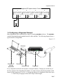
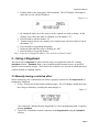
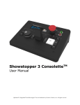
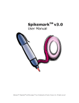
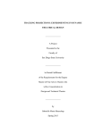
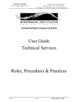
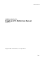
Stagehand FX Manual
creative conners, inc.
Stagehand FX Reference Manual
Version 1.0
Copyright © 2008. Creative Conners, Inc. All rights reserved.
Page 1
Stagehand FX Manual
Table of Contents
Stagehand ™ FX Reference Manual
1 – Getting Started
1.1 What’s in the box?......................................................................3
1.2 Stagehand FX Overview............................................................ 3
1.3 Installing Stagehand................................................................... 5
1.3.1 Mounting Stagehand........................................................... 5
1.3.2 Hooking up power...............................................................5
1.3.3 Hooking up a switched effect ............................................. 5
1.3.3 Hooking up an input switch................................................ 6
1.4 Configuring a Stagehand Network.............................................7
2 – Using a Stagehand
2.2 Manually testing a switched effect ............................................ 8
2.2 Cue Control with SpikeMark.................................................... 9
3 – Troubleshooting
Technical Support ............................................................................ 9
Phone Support ..............................................................................9
Web Support.................................................................................9
Email.......................................................................................... 10
4 – Specifications
4.1 Physical Specifications............................................................ 10
4.2 Electrical Specifications...........................................................10
Page 2
Stagehand FX Manual
Stagehand ™ FX Reference Manual
1 – Getting Started
Congratulations on your purchase of the Stagehand FX scenic input/output controller from
Creative Conners, Inc. Stagehand FX brings the excitement of automation to theatres of all
sizes. Stagehand FX is made to integrate simple switch devices into shows that are using
Stagehand motor controllers with our SpikeMark software.
This manual will direct you through:
1. Unpacking
2. Installing & testing
3. Operation procedures
If you need help along the way contact us either on our website (www.creativeconners.com), via
email ([email protected]), or by phone (401.862.2980)
1.1 What’s in the box?
Inside the box you should find:
1. Reference manual (this document)
2. Stagehand FX
3. Power cord
If you purchased any Stagehand motor controllers, power cables, encoders, limit switches, or
other accessories, those items are packaged separately.
1.2 Stagehand FX Overview
The Stagehand FX performs two functions: switching relay outputs & sensing switch-closure
inputs. This means that Stagehand FX can:
1. Turn on & off a power source to a simple effect like a solenoid valve, lights, or small
motors.
2. Detect when a switch has been closed (eg. a limit switch or pushbutton).
After unpacking your Stagehand FX, take a moment to familiarize yourself with its various
connections and features.
Page 3
Stagehand FX Manual
Figure 1.1 shows the connections and controls located on the front of the Stagehand FX. From
left to right, these connections are:
Figure 1.1
1.
2.
3.
4.
5.
6.
7.
Knob – The knob is used to set the IP address. Press the knob (it’s also a button) and then
turn the knob to adjust the address.
LCD Display – The display shows information about the Stagehand’s status. When idle, it
shows the current IP address and the status of the network connection between the
Stagehand and a PC running SpikeMark. If an E-Stop has been activated, the condition
will be displayed. In address mode, it will let you alter the current IP address.
Ethernet – The Ethernet receptacle accepts a standard RJ45 network cable. Stagehand
FX uses Ethernet as the control protocol to communicate with a PC running SpikeMarkTM
software.
Output Indicators – When the Stagehand FX closes an output switch, the corresponding
indicator light will illuminate.
Output Connector - The pluggable terminal block provides screw terminals to make
connections to the four (4) relay outputs. The relay outputs are dry contact closures
allowing you to switch an power source you need. The contacts are rated for 3A 120VAC
maximum.
Input Connector – The pluggable terminal block provides screw terminals to make
connections to the four (4) inputs. The Stagehand FX will supply 12V on one terminal of
each input and sense the presence of that voltage on the other terminal of the input. You
can wire any normally open (N.O.) switch rated for at least 12VDC to the inputs.
E-Stop – The E-Stop (a.k.a. emergency stop) receptacle is a 5-pin XLR connector. This
receptacle receives a dedicated emergency signal (24VDC) from a Showstopper base
station. If this signal is present, the Stagehand FX is free to close any output, when the
signal is interrupted it will immediately open all relay outputs.
Page 4
Stagehand FX Manual
Figure 1.2
Figure 1.2 shows the power connection located on the back of the Stagehand FX. The input
power connector is fused with a 5mm x 20mm glass fuse rated for 1.25A.
1.3 Installing Stagehand
1.3.1 Mounting Stagehand
The Stagehand FX is packaged in a standard 2U 19” rackmount case. You can mount in a 19”
rack, or simply set it on any flat surface. Take care not to block the ventilation slots on the sides
of the case.
1.3.2 Hooking up power
Once you have plugged in the Stagehand FX power cord, the LCD display should light up and
display the following (note: IP address may be different).
Figure 1.9
The “E-Stop!!” message is displayed because you have not yet hooked up the Stagehand with
Showstopper. If the Stagehand does not detect a signal from Showstopper, it will assume and
Emergency Stop condition.
The number on the bottom line of the display is the Stagehand’s IP address. We’ll look at
changing the IP address in section 1.4.
1.3.3 Hooking up a switched effect
Page 5
Stagehand FX Manual
The Stagehand FX has four (4) switched outputs that can be used to control any simple on/off
device. The switched outputs located on the front panel are dry contact closures, in other words,
the Stagehand FX doesn’t provide any power from those outputs just a switch closure. Figure
1.10 shows a typical output connection.
Figure 1.10
Stagehand FX Outputs Internal Control
1
2
3
4
solenoid valve
- +
external
power supply
1.3.3 Hooking up an input switch
The Stagehand FX has four (4) inputs that can be used to detect a switch closure. By using
normally open switch connected to a Stagehand FX input, you can trigger cue links in the
SpikeMark software when the switch is closed. Figure 1.11 shows a typical input connection.
Figure 1.11
Page 6
Stagehand FX Manual
Stagehand FX Inputs Internal Control
2
3
1
4
opto-isolator
opto-isolator
opto-isolator
opto-isolator
+12VDC
+12VDC
+12VDC
+12VDC
1.4 Configuring a Stagehand Network
Many Stagehands can be controlled by a single PC running SpikeMark software. The SpikeMark
controls Stagehands through standard network cables and hubs. The following diagram shows a
typical network of Stagehands.
Figure 1.13
ethernet
e-stop
Windows PC
running
SpikeMark
Showstopper
Network Hub
Stagehand
Effects
Every component on the network must have a unique IP address. Though you can alter any of
the four segments of the Stagehand’s IP address, it is often easiest to alter the last number (valid
ranges for each segment are 0 to 255). To change the address of a Stagehand, follow these steps:
1. If the E-Stop is engaged, release the E-Stop on Showstopper.
Page 7
Stagehand FX Manual
2. Push the knob on the front panel of the Stagehand. The LCD display will change to
show that you can edit the IP address.
Figure 1.14
3. By turning the knob, move the cursor over the segment you wish to change. In this
example, move the cursor until it is flashing over the number “32”.
4. Press the knob to edit the number “32”.
5. Turn the knob to dial in a new number, for example rotate clockwise until you reach
the number “36”.
6. Press the knob to stop editing the number.
7. Rotate the knob until the cursor is flashing on “OK”.
8. Press the knob to accept the changes.
Note: To discard a changed IP address, you can click on Cancel in step 7.
2 – Using a Stagehand
The real benefit of Stagehand is achieved when using it in conjunction with a PC running
SpikeMark software. SpikeMark allows you to program multiple motors to move at specified
speeds to exact locations on stage. These moves are written as cues and can be edited and run in
a similar fashion to a lighting console.
2.2 Manually testing a switched effect
Before writing any cues, confirm that your effect is properly connected to the Stagehand FX by
testing these conditions:
1. E-Stop – Release the E-Stop button on Showstopper. The LCD display should show that
the E-Stop is released by switching the status display to:
Figure 2.1
“Not Connected” indicates that the Stagehand FX is not communicating with a computer
running SpikeMark.
2. Connection - Establish a network connection to the Stagehand FX using the SpikeMark
software.
Page 8
Stagehand FX Manual
3. Output - In SpikeMark, using the on-screen manual controls to close the output on the
Stagehand FX. The output light on the Stagehand FX should illuminate. For more
details, see the SpikeMark user manual.
Figure 2.2
2.2 Cue Control with SpikeMark
Stagehand FX receives cue information from SpikeMark over standard network cables and hubs.
SpikeMark will inform Stagehand FX which output switches to open or close. When SpikeMark
sends a “GO” command, Stagehand will open or close the selected outputs, thereby activating or
deactivating your switched effects.
If an Emergency Stop signal is detected from the Showstopper, the Stagehand FX will
immediately disable all of its output switches. Keep this in mind when designing your effects,
because it means that your effect should be in a safe state if power is removed from the
activation circuit.
For more details on writing cues in SpikeMark, consult the SpikeMark user manual.
3 – Troubleshooting
Technical Support
Though we try our best to produce reliable software and clear instructions, there may come a
time when you need personal support.
Phone Support
You can call our technical support at 401-862-2980 Monday-Saturday from 8am – 6pm EST.
Phone support is free for 90 days, after that a rate of $30/hr. applies to support calls.
Web Support
There is an active user support forum on our website. http://www.creativeconners.com/phpBB2/
index.php
Page 9
Stagehand FX Manual
Email
If you have a technical question you can email technical support [email protected].
4 – Specifications
4.1 Physical Specifications
The Stagehand FX is packaged in a standard 19” x 2U rackmount case. The overall dimensions
are: 17”W x 8”D x 3-7/16”H.
4.2 Electrical Specifications
Power supply voltage
Max power supply current
Switched output contact rating
Control input rating
120V 60Hz
1.25 amps
3A @ 125VAC
dry contact closure
Page 10