1
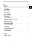
VE.Net to VE.Bus protocol Converter (VVC) USER MANUAL INSTALLATION MANUAL Copyrights 2008 Victron Energy B.V. All Rights Reserved This publication or parts thereof, may not be reproduced in any form, by any method, for any purpose. For conditions of use and permission to use this manual for publication in other than the English language, contact Victron Energy B.V. VICTRON ENERGY B.V. MAKES NO WARRANTY, EITHER EXPRESSED OR IMPLIED, INCLUDING BUT NOT LIMITED TO ANY IMPLIED WARRANTIES OF MERCHANTABILITY OR FITNESS FOR A PARTICULAR PURPOSE, REGARDING THESE VICTRON ENERGY PRODUCTS AND MAKES SUCH VICTRON ENERGY PRODUCTS AVAILABLE SOLELY ON AN “AS IS” BASIS. IN NO EVENT SHALL VICTRON ENERGY B.V. BE LIABLE TO ANYONE FOR SPECIAL, COLLATERAL, INCIDENTAL, OR CONSEQUENTIAL DAMAGES IN CONNECTION WITH OR ARISING OUT OF PURCHASE OR USE OF THESE VICTRON ENERGY PRODUCTS. THE SOLE AND EXCLUSIVE LIABILITY TO VICTRON ENERGY B.V., REGARDLESS OF THE FORM OF ACTION, SHALL NOT EXCEED THE PURCHASE PRICE OF THE VICTRON ENERGY PRODUCTS DESCRIBED HEREIN. Victron Energy B.V. reserves the right to revise and improve its products as it sees fit. This publication describes the state of this product at the time of its publication and may not reflect the product at all times in the future. -1- Index 1 Introduction .....................................................................3 1.1 Introduction to VE.Net................................................3 1.2 The VE.Net to VE.Bus protocol Converter (VVC) ......3 2 Supported Devices..........................................................4 3 Installation and setup of your VVC ..................................5 3.1 Requirements ............................................................5 3.2 Wiring and jumpers....................................................5 3.2.1 VE.Bus.....................................................6 3.2.2 VE 9-bit RS485 ........................................6 4 Using the VVC.................................................................8 5 Remote Panel .................................................................9 5.1 VE 9-bit RS485 ..........................................................9 6 Parallel and multi-phase systems..................................10 6.1 VE.Bus.....................................................................10 6.2 VE 9-bit RS485 ........................................................10 7 VE.Bus system configuration ........................................12 8 Shore current control.....................................................14 8.1 Default current limit..................................................14 8.1.1 VE.Bus...................................................14 8.1.2 VE 9-bit RS485 ......................................14 8.2 Shore current limit....................................................15 8.3 Shore current range.................................................15 8.3.1 VE.Bus...................................................16 8.3.2 VE 9-bit RS485 ......................................16 9 Alarms...........................................................................17 10 Caching.........................................................................18 11 Menu layout...................................................................19 -2- 1 Introduction Victron Energy has established an international reputation as a leading designer and manufacturer of energy systems. Our R&D department is the driving force behind this reputation. It is continually seeking new ways of incorporating the latest technology in our products. Each step forward results in value-added technical and economical features. 1.1 Introduction to VE.Net VE.Net stands for Victron Energy Network. It allows all VE.Net compatible devices to communicate with each other. This means that the charger for example can get information from the battery controller to optimise the charge current. It is possible to control and monitor all your VE.Net devices from a single VE.Net compatible control panel. This saves space and allows you to control all your devices from one place. 1.2 The VE.Net to VE.Bus protocol Converter (VVC) The purpose of the VVC is to combine the powerful control of the VE Configure software, with the simple interface of the VE.Net Panel. With the VVC, you can configure the advanced features, and view status information of your VE.Bus device from a VE.Net Panel. -3- 2 Supported Devices The VVC works with all VE 9-bit RS485 devices with software version 17xx130 and higher, and 18xxxxx; and all VE.Bus devices with software version 19xx111 and higher. This includes the following products: Phoenix Multi Phoenix Multi Plus Phoenix Multi Compact Phoenix Inverter Phoenix Inverter Compact Phoenix Charger Quattro -4- 3 Installation and setup of your VVC Unless specifically stated otherwise, all instructions regarding VE.Bus devices also apply to VE 9-bit RS485 devices. 3.1 Requirements To install your VVC, you will need: • • • • Power cable Two Cat5 cables, each with two RJ45 connectors (one for VE.Net, and one for VE.Bus) VE.Net Panel (VPN) (Must have a software version of 1.07 or higher) Optional - Remote panel and additional Cat5 cable with two RJ45 connectors 3.2 Wiring and jumpers Connect one of the sockets labelled VE.Net either to your existing VE.Net system, or directly to a VPN. If you are connecting directly to a VPN, jumpers will need to be placed on JP1 and JP2, to allow the VVC to supply power the VPN. The total length of Cat5 cables in a VE.Net network should not exceed 100 meters. Note: JP3, JP4, and JP6 should be placed at all times. The VVC is supplied with all jumpers placed. -5- 3.2.1 VE.Bus Connect one of the sockets labelled VE.Bus to a spare socket on one of the target devices. Refer to the manual of the target device for more detailed instructions regarding the cabling requirements. A remote panel can also be used, by connecting to an empty RJ45 socket on either the target system, or the VE.Bus side of the VVC. 3.2.2 VE 9-bit RS485 Connect one of the sockets labelled VE.Bus to the target device. In a parallel system, the VVC must be connected to the master device. A remote panel can also be used, by connecting to the other VE.Bus socket on the VVC. Warning: Do not confuse the connectors on the converter. VE.Bus/VE 9-bit devices must only be plugged into the sockets labelled VE.Bus, and VE.Net devices must only be plugged into the sockets labelled VE.Net. Incorrect wiring could result in permanent damage to connected devices. -6- Figure 3-1 - Jumper locations Connect the power terminals to the battery using 1.5mm2 wire. Figure 3-2 - Wiring diagram -7- 4 Using the VVC When power is first applied to the VVC, the activity LED will flash rapidly for approximately 2 seconds. The VVC will then begin communicating with the target device(s), and determine which features are supported. Whenever there is communication between the VVC and the target, the status LED will blink slowly. Hold down one of the buttons on the VPN, until it starts up. If this is the first time you have connected this device to the VVC, you may be prompted to restart the panel. You should do this now. New device found Restart Panel If you have only connected a VPN, then you will now be able to see the VVC’s device entry. If you have other VE.Net devices connected, you may have to scroll through the list first. Phoenix Multi Switched Off The first line of the VPN will display the type of device you have connected, and the second will show the current state of the device. Press “Enter” to view the VVC menu. You will now be able to scroll through a list of information and settings relating to the device that you have connected. For more information on the different options, refer to chapter 11 - Menu layout. -8- 5 Remote Panel The VVC can work in parallel with a traditional remote panel, such as a Phoenix Multi Control, or Phoenix Charger Control. When connected, the remote panel will take control of the shore current limit and the switch setting, so changing these properties on the VPN will have no effect. All other features of the VVC are still available when the remote panel is connected. When the remote panel is disconnected, the VVC will automatically resume control of the switch and shore current settings. 5.1 VE 9-bit RS485 When using a remote panel in a VE 9-bit RS485 system, it is recommended that the remote panel is disconnected when connecting a new target, restoring system defaults, or loading/saving user defaults. These features will function correctly with the remote panel connected, but will take significantly longer. -9- 6 Parallel and multi-phase systems 6.1 VE.Bus The VVC will automatically detect the parallel/multi-phase configuration of a VE.Bus system, and display the systemwide A.C./D.C. information in the top level menu. The device specific values are also available from the “Device specific” menu (under the “Advanced” menu). Before changing or viewing settings, or viewing properties in the “Device specific” menu, it is important to make sure that the correct device has been selected. The “Current device” property in the “VE.Bus device” menu is used to select the device to be configured. Devices are identified by number, however it may not be clear which number relates to which physical device. After selecting a device, the “Flash LEDs” property can be used to make the LEDs on the selected device flash. Set this property back to “No” to resume normal LED functionality. 6.2 VE 9-bit RS485 The VVC should be connected to the master device. By default, the VVC handles current readings and settings for the master device only. In order to make sure that the information from the VVC reflects the system as a whole it is necessary to set the “Current factor” property (“VVC” menu) to the correct value. This property simply multiplies the current value received from the device by the value you -10- specify. Normally this property should be set to the number of devices in the system. Note: This setting does not affect the shore current control (please refer to chapter 8 - Shore current control). -11- 7 VE.Bus system configuration The VVC can be used to set up the parallel/multi-phase configuration for simple VE.Bus systems of up to three devices. The “VE.Bus sys setup” property on the “VE.Bus device” menu displays the current system configuration. To re-configure the system, first determine which physical device will perform which function (for example, master/slave, or phase leader/follower). Next select one of the pre-defined system configurations with the “VE.Bus sys setup” property. The VPN will then prompt you to switch the device(s) off and then back on in a specific order. After each step has been completed, press “Enter” on the VPN. Once configuration is complete, you may be prompted to restart the VPN. No changes are made to the system configuration until the last device has been switched on, and acknowledged on the VPN. The configuration procedure can be aborted at any time before this point by pressing “Cancel”. The supported configurations are: • • • • • • • 2 parallel devices. 3 parallel devices. Split phase 120°. Split phase 180°. Split phase 240°. Split phase floating. Stand alone. -12- For more complex systems, VE.Bus System Configurator should be used (available as a free download from www.victronenergy.com). Note: before re-configuring a VE.Bus system, check the A.C. cabling to ensure that it is suitable for the new configuration. -13- 8 Shore current control When using a Multi or Quattro, it is often the case that the system is capable of drawing more current than is actually available from the shore or generator supply. It is possible to limit the amount of current that the system will actually draw, preventing the supply from becoming overloaded. There are three settings which control the shore current regulation. How these settings are used depends on the connected equipment. 8.1 Default current limit This is the maximum current that will be drawn if there is no remote panel or VVC connected. If the target device is a Quattro, then the limit for each A.C. input must be configured separately. This setting can be changed on the “Transfer switch” menu. 8.1.1 VE.Bus This setting indicates the maximum current that will be drawn per device for parallel systems, and per phase for multi-phase systems. 8.1.2 VE 9-bit RS485 For parallel systems where the master device has the “Number of slaves” property set to zero, this property refers to the maximum current that will be drawn by each device. -14- In other parallel systems, this represents the maximum current that will be drawn by the system as a whole. 8.2 Shore current limit When a VVC is connected the default shore current limit is overruled by this setting (root menu). If a remote panel is connected, this property will show the value that is set by the remote panel. If the VVC and remote panel are removed, the Multi will revert to the default current limit. Note: If the target device supports the “ACIN uses PMC” option (“Transfer switch” menu), and the value set to “No”, this property will be ignored, and the default current limit will be used instead. 8.3 Shore current range This setting (“VVC” menu) determines the maximum value that can be used for the shore current limit. This value should be set to the maximum current that the system is capable of drawing (assuming sufficient power is available). The maximum current depends on the configuration of the devices, and the size of the mains relay in each device. The size of the mains relay depends on the type of device used. This is usually 16A for 230V models and 32A for 110V models. -15- 8.3.1 VE.Bus The maximum current that can be drawn is equal to the sum of the size of the mains relay in each device. Note: If this setting is set to a value higher than the system is actually capable of drawing, it will be possible to set a shore current limit that the system cannot handle. This will not cause any damage, but the system will also never draw that much current, even if there is sufficient power available. 8.3.2 VE 9-bit RS485 The maximum current that can be drawn is the same as the size of the mains relay in the master device, unless the “Number of slaves” property is set to 0. In this case, the maximum is equal to size of the mains relay in the master device, multiplied by the number of devices. Note: If this value is not set correctly, the shore current limit displayed on the VPN will not match the actual limit used by the system. -16- 9 Alarms The VVC can cause the VE.Net panel to generate an alarm if a fault is detected on the connected device. The VVC supports 5 alarms: overload, low battery, high temperature, connection lost, and wiring error. If a fault occurs, the VPN will display a message warning of an alarm, until it is acknowledged by pressing “Cancel”. Note: If you hide an alarm, you will not be reminded of the problem again. With the exception of the wiring error, all alarms can be disabled on the “Alarms” menu. Note: The wiring error alarm can only detect certain types of wiring error. -17- 10 Caching When a setting is viewed on the VPN, the VVC will request the value from the target, and then send the reply to the VPN. If the target device takes too long to respond (for example it is busy communicating with the remote panel), the VPN will display the message “Retrieving…”, until the response is received. By enabling caching (under the advanced menu), the VVC will reply with the most recently retrieved value for that setting, whilst it waits for the target to respond. When the new value is received, it will be sent to the VPN. With caching enabled, values will be shown more quickly, but may not represent the state of the target device exactly. By default, caching is enabled. -18- 11 Menu layout The VVC menu structure is shown in Figure 11-1 - VVC menu layout. Table 11-1 describes in more detail, the contents of each menu. Figure 11-1 - VVC menu layout If the panel has been set to “user” access level, items marked with * are hidden. For more information on access levels, refer to the VPN manual. Note: Only the options supported by the currently connected system will be shown in the menu. In systems with multiple A.C. inputs/outputs, some properties will appear multiple times. -19- Items marked with † require a panel restart before the changes will be properly registered. Settings under the “VVC” menu are stored in the VVC, and not the target device. This means that the value will be remembered if you connect a different target (and conversely, if the VVC is replaced, these settings will need to be re-configured). Warning: An incorrectly configured device can cause damage to the system. Before changing any options make sure you know the associated risks. The descriptions below are summaries only; if in doubt consult the manual for the target device, or your Victron dealer. Table 11-1 - VVC menu summary Name Root menu Device switch Information / Setting Details Setting Use this to turn the system on or off. The maximum current to draw from the shore supply. The maximum percentage of the charge current setting to utilise. Indicates the current status of the system. The battery voltage. Shore cur. limit Setting Charge current Setting Device state Information DC voltage Information DC current Information -20- The D.C. current flow between the battery and the target system. Mains AC voltage Mains AC current Mains AC power Information Information Information Mains frequency Inv. AC voltage Information Inv. AC current Inv. AC power Information Information Inv. frequency Information Information VE.Bus/VE 9-bit device menu Current Setting device Flash LEDs Setting System defaults Setting -21- The voltage of the mains power supply. The current being drawn from the mains supply. The power being consumed from the mains supply. The frequency of the mains supply. The voltage being produced by the inverter. The current drawn from the inverter. The power consumed from the inverter. The frequency of the inverter output. Selects the device to communicate with for configuration options, and values in the “Device specific” menu. Flash the LEDs on the device selected with the “Current device” property. Restore all target settings to their default values. VE.Bus sys setup General menu Sys. frequency Setting The current configuration of the VE.Bus system. See chapter 7 - VE.Bus system configuration for more information. Setting The frequency of the mains supply in your region. Number of slaves in a parallel system. The Multi is part of a multi-phase system. Set this Multi to be a leader in a multi-phase system. The phase configuration of the mains supply. Number of slaves Enable multiphase Leader multiphase Setting Phase setting Setting Setting Setting Transfer Switch menu Wide input Setting freq. Ground relay Setting AC low discon. Setting Allows the A.C. input frequency to be anywhere from 45 – 65 Hz Enable this for systems with an earth leakage circuit breaker. The voltage at which the transfer switch will disconnect the A.C. supply, and switch to the inverter. -22- AC low connect Setting AC high discon. AC high connect UPS function Setting The voltage above the disconnect voltage at which the transfer switch will re-connect the A.C. See “AC low discon.” Setting See “AC low connect” Setting Dyn. cur. lim. Setting Default cur lim Setting ACIN uses PMC Setting Enables or disables the fast checking of the A.C. waveform. Disabling this will result in slower transfer speeds, but will be more tolerant of poor input signals. When enabled, the inverter will be started if the load increases rapidly, to avoid voltage drops as the generator adjusts to the new load. The value that will be used for the shore current limit, if no VVC or remote panel is connected to the target. If this setting is enabled, then the VVC or a PMC can overrule the “Default cur lim” property. See chapter 8 - Shore current control for more information. -23- Inverter menu Inverter voltage DC Low Shutdown Setting The desired output voltage of the inverter. The inverter will switch off when the battery voltage drops to this level. The inverter will restart when the battery voltage rises this far above the shutdown voltage. If enabled, the inverter will start up if the current consumption becomes too high, to prevent tripping the external breaker. Used to calculate the required current during PowerAssist. Reduces the current drawn when the inverter load is low, but can take more time to switch to full load. When power consumption drops below this point AES will be activated if it is enabled. AES mode will be deactivated if power consumption rises above this level. Setting DC low restart Setting PowerAssist Setting Boost factor Setting AES Setting Start AES below Setting Stop AES above Setting -24- AES type Setting Selects the waveform type to be used during AES operation. Charger Settings menu Enable Setting charger Weak AC Setting input Stop after 10 hr Setting Battery type Setting Storage mode Setting Use TPTB curve Setting Charging chars Setting Absorption voltage Setting Switch the charger on or off. Enable this setting if poor A.C. input cause charging problems. Enable this setting to prevent overcharging damaged batteries. Disable this setting if your battery requires a bulk period of more than 10 hours. Select the type of battery that is connected. Enable this setting to use a voltage set point of 13.2V (for a 12V system); otherwise the normal float voltage will be used. Use the tubular plate traction battery charging curve. Select which charging algorithm should be used. Specify the absorption voltage to be used when charging. -25- Float voltage Setting Charge current Setting Rep abs time Setting Rep abs interval Setting Max abs time Setting VVC menu †Device name Setting Auto shore curr. Setting †Shore cur. range Setting Current factor Setting Cache values? Setting Specify the float voltage to be used when charging. The amount of current used to charge the battery. Specify the duration of repeated absorption pulses. Specify the interval between repeated absorptions. Specify the maximum period of time the absorption phase should last. The name that will appear in the VPN’s device menu. If this setting is enabled, when the shore current is connected, the shore current limit will be displayed automatically. The maximum current that the system is capable of drawing. The amount to scale the current values. Enable or disable value caching. -26- Save settings Setting Load settings Setting Software version Device address Information Alarms menu Low battery Information Setting High temperature Setting Overload Setting Charger failure Setting Save a copy of the current settings in the VVC. Load the saved settings into the current device (this device must have the same software version as the device from which these values were copied). The firmware version of the VVC. The device address for the VVC. Disable this option to prevent the VVC from generating an alarm when the battery is low. Disable this option to prevent the VVC from generating an alarm when the temperature is high. Disable this option to prevent the VVC from generating an alarm in the event of an overload. Disable this option to prevent the VVC from generating an alarm in the event of a charger failure. -27- Connection lost Setting Disable this option to prevent the VVC from generating an alarm when the connection to the target device is lost. Advanced menu Active AC Information input DC voltage RMS Information PMC present Information Device type Information Software version Protocol Information Information IDC (invert) Information IDC (charge) Information †Redetect system Setting -28- The currently active A.C. input (or the last active input if there is currently no mains supply). Displays the measured ripple voltage of the D.C. input. A Phoenix Multi Control (or other remote panel) has been detected. The type of target device connected. The software version of the target device. The protocol used by the target system (VE.Bus or VE 9-bit RS485). The total current drawn from the battery by all inverting phases. The total current supplied to the battery by all charging phases. Redetect the supported features and parallel/multi-phase configuration of the system. Device specific menu DC current Information Mains AC voltage Information Mains AC current Information Mains AC power Information Mains frequency Information Inv. AC voltage Information Inv. AC current Information Inv. AC power Information Inv. frequency Information -29- The D.C. current between the battery and the selected device. The voltage of the mains supply to the selected device. The current drawn from the mains supply by the selected device. The power being consumed from the mains supply by the selected device. The frequency of the mains supply to the selected device. The voltage being produced by the inverter of the selected device. The current drawn from the inverter of the selected device. The power consumed from the inverter of the selected device. The frequency of the inverter output of the selected device. -30- Victron Energy B.V. De Paal 35 1351 JG Almere PO Box 50016 1305 AA Almere The Netherlands Version: Date: 8 03 September 2008 w w w . v i c t r o n e n e r g y .c o m