1
T
ABLE OF CONTENTS
TABLE OF CONTENTS..................................................................I.
PART 1 PRODUCT (GENERAL)....................................................1.
1.1--PRODUCT INTRODUCTION.........................................................2.
1.2--PRODUCT FEATURES.................................................................2.
1.3--TECHNICAL SPECIFICATIONS.....................................................3.
1.4--PHOTOMETRIC DATA..................................................................4.
1.5--SAFETY WARNING......................................................................5.
PART 2 INSTALLATION...............................................................6.
2.1--MOUNTING...................................................................................7.
2.2--POWER CONNECTION..................................................................7.
2.3--SETTING UP WITH A DMX512 CONTROLLER.................................8.
2.3-1--DMX512 ADDRESSING WITHOUT ID ADDRESSING......................................8.
2.3-2--DMX512 ADDRESSING WITH ID ADDRESS..................................................8.
2.4--SETTING UP WITH THE PiX CONTROLLER...................................9.
2.4-1--SINGLE ROW APPLICATION.........................................................................9.
2.4-2--STANDARD BLOCK APPLICATION..............................................................10.
2.4-3--REPEAT ROW BLOCK APPLICATION...........................................................11.
2.5--OPERATION WITH DMX512 Vs PiX CONTROLLER.......................12.
PART 3 DISPLAY PANEL OPERATION.......................................13.
3.1--BASIC........................................................................................14.
3.2--MENU........................................................................................15.
3.3--CREATING A STATIC COLOR......................................................16.
3.4--DMX512 SETTINGS....................................................................16.
3.5--ACTIVATING AN AUTO PROGRAM..............................................17.
3.6--CHANGING THE SETTINGS........................................................17.
3.7--ACTIVATE THE PASSWORD.......................................................18.
3.8--POWER ON/OFF.........................................................................18.
3.9--RGB CHANNEL MODEL .............................................................18.
PART 4 USING A DMX512 CONTROLLER....................................19.
4.1--BASIC ADDRESSING.................................................................20.
4.2--CHANNEL ASSIGNMENT............................................................20.
4.3--BASIC INSTRUCTIONS FOR DMX512 OPERATION......................23.
PART 5 USING THE CONTROLLER.............................................24.
5.1--BASIC.......................................................................................25.
5.2--SETTING UP.............................................................................27.
5.3--MENU.......................................................................................27.
5.4--CUSTOM PROGRAM..................................................................28.
5.5--PLAY SCHEDULE......................................................................29.
5.6--CLOCK.....................................................................................29.
5.7--SCHEDULE...............................................................................29.
5.8--SETTINGS................................................................................30.
5.9--ACTIVATE THE PASSWORD.......................................................31.
5.10--PIX CONTROLLER EXTERNAL CONTROL VIADMX512.............31.
5.11--MAINTENANCE........................................................................33.
TABLE OF CONTENTS
I
2007.03.10
1
PRODUCT (GENERAL)
1.1
1.2
1.3
1.4
1.5
1 PRODUCT(GENERAL)
PRODUCT INTRODUCTION
PRODUCT FEATURES
TECHNICAL SPECIFICATIONS
PHOTOMETRIC DATA
SAFETY WARNING
1
2007.03.10
1.1
PRODUCT INTRODUCTION
This product is designed for indoor or outdoor use. Suitable applications include wash or
effect lighting for architectural, stage or nightclub applications. This product can also be
installed for use in signage and advertising using the dynamic functions available with
DMX512 control. Direct input of DMX512 signal allows the units to be controlled from any
DMX512 controller. This product can be operated as a single unit or in multiple units for
large applications.
The specially developed controller that allows the product to be controlled independent of
the DMX512 controller enables the user to create and edit a wide range of custom programs.
All programs can be touch-button displayed or scheduled to START and END at scheduled
times. When programs have been created or edited in the controller, it is also possible to
trigger these programs using the DMX IN function when connected to a DMX512 controller.
1.2
PRODUCT FEATURES
LED FIXTURE
* RGB Dimmer 0-100%
* Strobe
* Automatic programs
* IP65 protection rating
* LED display
* Display control 'lock-out'
* Direct DMX512 input
* Independant ID address
* Lightweight aluminium casing
PiX CONTROLLER
*
*
*
*
*
*
*
*
*
*
1 PRODUCT(GENERAL)
RGB Dimmer 0-100%
Strobe
Clock & Timer
Automatic programs (wash & effect)
Custom programs
Program Schedule
LCD display
Display control 'lock-out'
Direct DMX512 input
Lightweight plastic casing
2
2007.03.10
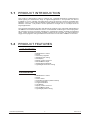
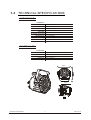
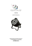
1.3
TECHNICAL SPECIFICATIONS
LED MODULE
LED MODULE:
Voltage
90~250V...50/60Hz
Rated Power
65W
IP65 protection rating
IP
36pcs (12 x RED / 12 x GREEN / 12 x BLUE)
LED/Unit
Output/LED
1W
Environment Temperature -20 ~40
LED Beam Angle
15 (30 Optional)
Cooling
Direct air convection
Dimensions
235 x 165 x 300mm
Weight
4Kg
CONTROLLER
CONTROLLER:
Voltage
220~240V, 50/60Hz......100~120V, 50/60Hz
1.5W
Rated Power
IP33 protection rating
IP
180 x 125 x 49mm
Dimensions
Weight
0.7Kg
235mm
165mm
1 PRODUCT(GENERAL)
3
2007.03.10
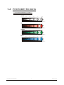
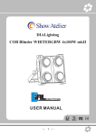
1.4
PHOTOMETRIC DATA
PHOTOMETRIC DATA
WHITE
3
2
1
0
1
2
3
27 50
70 0
32 0
19 0
2(0 .52 )
4(1 .05 )
6(1 .57 )
8(2 .10 )
11 45
29 0
13 0
72
2(0 .52 )
4(1 .05 )
6(1 .57 )
8(2 .10 )
17 63
57 0
27 0
15 8
2(0 .52 )
4(1 .05 )
6(1 .57 )
8(2 .10 )
30 7
98
46
27
2(0 .52 )
4(1 .05 )
6(1 .57 )
8(2 .10 )
14 5 LU X
10 Dist ance (m)
(2. 60D iame ter( m))
RED
3
2
1
0
1
2
3
50 LU X
10 Dist ance (m)
(2. 60D iame ter( m))
GREEN
3
2
1
0
1
2
3
12 8 LU X
10 Dist ance (m)
(2. 60D iame ter( m))
BLUE
3
2
1
0
1
2
3
1 PRODUCT(GENERAL)
4
22 LU X
10 Dist ance (m)
(2. 60D iame ter( m))
2007.03.10
1.5
SAFETY WARNING
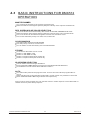
IMPORTANT
ALWAYS READ THE USER MANUAL BEFORE OPERATION.
PLEASE CONFIRM THAT THE POWER SUPPLY STATED ON THE
PRODUCT IS THE SAME AS THE MAINS POWER SUPPLY IN YOUR
AREA.
This product must be installed by a qualified professional.
Always operate the equipment as described in the user manual.
A minimum distance of 0.5m must be maintained between the equipment and
combustible surface.
The product must always be placed in a well ventilated area.
Always make sure that the equipment is installed securely.
DO NOT stand close to the equipment and stare directly into the LED light
source.
Always disconnect the power supply before attempting and maintenance.
Always make sure that the supporting structure is solid and can support the
combined weight of the products.
The earth wire must always be connected to the ground.
Do not touch the power cables if your hands are wet.
ATTENTION
This product left the place of manufacture in perfect condition. In order to
maintain this condition and for safe operation, the user must always follow the
instructions and safety warnings described in this user manual.
Avoid shaking or strong impacts to any part of the equipment.
Make sure that al parts of the equipment are kept clean and free of dust.
Always make sure that the power connections are connected correct and
secure.
If there is any malfunction of the equipment, contact your distributor
immediately.
When transferring the product, it is advisable to use the original packaging in
which the product left the factory.
Shields, lenses or ultraviolet screens shall be changed if they have become
damaged to such an extent that their effectiveness is impaired.
The lamp (LED) shall be changed if it has become damaged or thermally
deformed.
1 PRODUCT(GENERAL)
5
2007.03.10
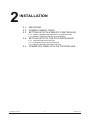
2
INSTALLATION
2.1
2.2
2.3
MOUNTING
POWER CONNECTIONS
SETTING UP WITH A DMX512 CONTROLLER
2.3-1 DMX512 ADDRESSING WITHOUT ID ADDRESSING
2.3-2 DMX512 ADDRESSING WITH ID ADDRESS
2.4
SETTING UP WITH THE PiX CONTROLLER
2.4-1 SINGLE ROW APPLICATION
2.4-2 STANDARD BLOCK APPLICATION
2.4-3 REPEAT ROW BLOCK APPLICATION
2.5
2 INSTALLATION
OPERATION: DMX512 Vs PiX CONTROLLER
6
2007.03.10
2.1
MOUNTING
HANGING
The LED PAR can be mounted in a hanging position using
the supporting bracket. The bracket should be secured to
the mounting truss or structure using a standard mounting
clamp. Please note that when hanging the unit a safety
cable should also be used.
UPRIGHT
The LED PAR can be mounted in an upright or
sitting position using the supporting brackets.
The LED MODULE can be mounted at any angle and in any
position. It is possible to further adjust the angle of the LED
MODULE using the two adjustment knobs located on the side of
the fixture.
2.2
POWER CONNECTIONS
@ 220V: 40 units may be connected in series
@120V: 20 units may be connected in series
2 INSTALLATION
7
2007.03.10
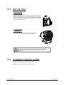
2.3
SETTING UP WITH A DMX512
CONTROLLER
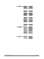
2.3-1 DMX512 ADDRESSING WITHOUT ID ADDRESSING
Connect the DMX512 controller to the units in series.
Each unit has 9 DMX channels so the DMX Addresses should increase by increments of
9 (e.g. 1,10,19,28...)
The ID address has not been set so therefore when using the controller CH8 must
be inactive ( CH8=0 ).
Each DMX Address may be used as many times as required.
Any DMX address in the range from 001 to 500 may be used.
Example:
DMX Addr.1
DMX Addr.10
DMX Addr.19
DMX512
CONTROLLER
The figure above shows a simple DMX512
layout with the starting address of the first
unit set at 1, with the second set at 10 and
so on... (Note that when used in this way,
the CH8 ID function must be inactive (CH8=0))
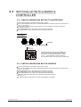
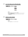
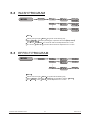
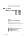
2.3-2 DMX512 ADDRESSING WITH ID ADDRESS
Connect the DMX512 controller to the units in series
Each unit has 9 DMX channels so the DMX Addresses should increase by increments of
9 (e.g. 1,10,19,28...)
Each DMX Address may be used as many times as required.
Any DMX address in the range from 001 to 500 may be used.
Each DMX address may carry up to 66 separate ID addresses.
ID should be set in the menu on each unit in ascending values
(i.e. 1,2,3...)
ID addresses are accessible from Ch8 on the DMX512 controller.
2 INSTALLATION
8
2007.03.10
Example:
DMX Addr.1
ID Addr.1
DMX Addr.1
ID Addr.2
DMX Addr.1
ID Addr.3
DMX512
CONTROLLER
2.4
DMX Addr.10
ID Addr.1
DMX Addr.10
ID Addr.2
DMX Addr.10
ID Addr.3
The figure above shows a simple DMX layout
which has used three units at each DMX address.
The three units have different ID addresses which
allows the user to collectively control the whole
group of units at that DMX address by setting
CH8 to 0, or to control each unit independently by
first selecting the DMX address and then by using
CH8 to locate the target ID address.
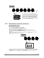
SETTING UP WITH THE PiX
CONTROLLER
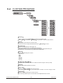
2.4-1 SINGLE ROW APPLICATION
Connect the fixtures to the PIXCONTROLLER in series.
ID Address should be set in the Id menu on each unit in ascending values
(i.e. 1,2,3...Not required for WASH programs).
When using the PIX CONTROLLER with the fixtures there is no need to set the DMX
address.
When using the Effect programs it is important to set the Range of fixtures in the
Settings menu of the PIX CONTROLLER.
Example:
ID Addr.1
ID Addr.2
ID Addr.3
ID Addr.4
CONTROLLER
MOD E
SETU P
UP
DOW N
In the figure above the PIX controller is connected in series to 4 units with corresponding
ID addresses from 1 to 4. In order to activate the Effect programs in the PIX CONTROLLER,
the Range must be set to 004 in the Settings menu of the PIX CONTROLLER.
2 INSTALLATION
9
2007.03.10
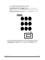
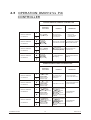
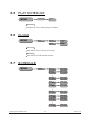
2.4-2 STANDARD BLOCK APPLICATION
Connect the fixtures to the PIX CONTROLLER in series in the direction that is required.
ID Address should be set in the Id menu on each unit in ascending values
(i.e. 1,2,3...Not required for WASH programs).
When using the Effect programs it is important to set the Range of fixtures in the
Settings menu of the PiX CONTROLLER.
Example:
ID Addr.1
ID Addr.2
ID Addr.3
ID Addr.4
ID Addr.5
ID Addr.6
ID Addr.7
ID Addr.8
ID Addr.9
CONTROLLER
MOD E
SETU P
UP
DO WN
In the figure above the PiX controller is connected in series to 9 units with corresponding
ID addresses from 1 to 9. In order to activate the Effect programs in the
PIX CONTROLLER, the Range must be set to 009 in the Settings menu of
the PIX CONTROLLER. (Note: it is possible to create different kinds of effects by changing
the direction and position of ID Addresses)
2 INSTALLATION
10
2007.03.10
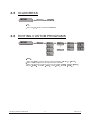
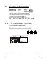
2.4-3 REPEAT ROW BLOCK APPLICATION
Connect the fixtures to the PIX CONTROLLER in series.
ID Address should be set in the Id menu on each unit in ascending order with
each row repeated (Not required for Wash programs).
When using the PRO-a CONTROLLER with the fixtures there is no need to set the DMX
address.
When using the Effect programs it is important to set the Range of fixtures in the
Settings menu of the Pix CONTROLLER.
Example:
ID Addr.1
ID Addr.2
ID Addr.3
ID Addr.1
ID Addr.2
ID Addr.3
ID Addr.1
ID Addr.2
ID Addr.3
CONTROLLER
MODE
S ETUP
UP
D OWN
In the figure above the PIX controller is connected in series to 9 fixtures with each row comprising
of 3 fixtures with corresponding ID addresses from 1 to 3. Each row is repeated so that the ID
addresses appear the same was as the first row. In order to activate the Effect programs in
the PIX CONTROLLER, the Range must be set to 003 in the Settings menu of the
PIX CONTROLLER.
2 INSTALLATION
11
2007.03.10
2.5
OPERATION: DMX512 Vs PiX
CONTROLLER
OPERATION WITH A DMX512 CONTROLLER
AVAILABLE
FUNCTIONS
DMX512 ADDRESS
ID ADDRESS
X
ID ADDRESS
DMX512 ADDRESS
Basic WASH
Programming
No need to set
up DMX Address
or ID Address
Advanced
WASH &
EFFECT
programming
Units are fully controlled
from DMX512 controller
X
DMX512 ADDRESS
X
X
ID ADDRESS
DRAWBACKS
Must locate
previosly stored
DMX Address
Programming requires
many DMX channels
Basic WASH
programming
DMX Address
ID address allows for
less DMX channels
when programming*
All ID addresses
must be set
Advanced
WASH &
EFFECT
programming
Advanced fixture
mapping
All ID addressesmust
be set
ID ADDRESS
DMX512 ADDRESS
BENEFITS
OPERATION WITH THE PiX CONTROLLER
AVAILABLE
FUNCTIONS
DRAWBACKS
No need to set up
DMX Address or
ID Address
Only control of all
units at the same time
X
Play WASH auto
programs, Basic
CUSTOM
programming &
Schedule play
DMX address not used
ID ADDRESS
Only control of all units
at the same time
X
Play WASH auto
programs, Basic
CUSTOM
programming &
Schedule play
DMX512 ADDRESS
X
DMX512 ADDRESS
ID ADDRESS
X
DMX512 ADDRESS
ID ADDRESS
DMX512 ADDRESS
ID ADDRESS
2 INSTALLATION
BENEFITS
Play WASH &
EFFECT auto
programs, Advanced
CUSTOM
programming &
Schedule play
DMX Address not used
Control speed and time of
all WASH &
EFFECT programs
Create powerful
CUSTOM programs
Schedule play
Trigger auto programs with
DMX IN
All ID Addresses
must be set
Play WASH &
EFFECT auto
programs, Advanced
CUSTOM
programming &
Schedule play
DMX Address not used
Control speed and time of
all WASH &
EFFECT programs
Create powerful
CUSTOM programs
Schedule play
Trigger auto programs with
DMX IN
All ID Addresses
must be set
12
2007.03.10
3
DISPLAY PANEL OPERATION
3.1 BASIC
3.2 MENU
3.3 ACTIVATING AUTO PROGRAMS
3.4 DMX512 SETTINGS
3.5 ID ADDRESS
3.6 EDITING CUSTOM PROGRAMS
3.7 SPECIAL SETTINGS
3.8 ACTIVATE THE PASSWORD
3.9 RGB CHANNEL MODEL
3 DISPLAY PANEL OPERATION
13
2007.03.10
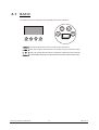
3.1
BASIC
The LED fixture is mounted with a LCD display and 4 control buttons.
POWER I N
POWER O UT
DMX IN
D MX O UT
MENU
MENU
SET
UP
SET
UP
DO WN
DOWN
scroll through the main menu or return to the main menu
enter the currently selected menu or confirm the current function value
scroll 'UP' through the menu list or increase the value of the current function
scroll 'DOWN' through the menu list or decrease the value of the current function
3 DISPLAY PANEL OPERATION
14
2007.03.10
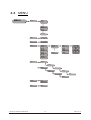
3.2
MENU
MENU
AUTO
AT.01
AT.02
AT.10
PR.C1
PR.C2
PR.C10
dMX
d 001
512
Id
I
IO66
Edi t
SET
001
PR.C1
PR.C2
PR.C3
PR.C4
PR.C5
PR.C6
PR.C7
PR.C8
PR.C9
PR.C10
SC.01
SC.02
SC.30
rEd
GrEn
bluE
Strb
TInE
FAdE
R. 0
G.
255
0
255
B. 0
255
S.
0
255
T. 0
255
F. 0
255
UP Ld
PASS
RE ST
***
PASS
Sen d
***
En d
rES T
3 DISPLAY PANEL OPERATION
PAS S
On
OFF
AR C
RGb
15
2007.03.10
3.3
ACTIVATING AUTO PROGRAMS
MENU
AUTO
AT.01
AT.02
AT.10
PR.C1
PR.C2
PR.C10
Auto
Select the target [Auto] program and press SET
Programs AT.01 to AT.10 are fully pre-programmed and will not be altered
by changes in EdIT mode
Programs PR.C1 to PR.10 are fully pre-programmed and can be edited
in EdIT mode
3.4
DMX512 SETTINGS
MENU
dMX
d 001
512
dMX
Enter the dMX
3 DISPLAY PANEL OPERATION
mode to set the DMX ADDRESS.
16
2007.03.10
3.5
ID ADDRESS
MENU
Id
I
001
IO66
Id
Enter the Id
3.6
mode to set the ID ADDRESS
EDITING CUSTOM PROGRAMS
MENU
Ed it
PR.C1
PR.C2
PR.C3
PR.C4
PR.C5
PR.C6
PR.C7
PR.C8
PR.C9
PR.C10
SC.01
SC.02
SC.30
rEd
GrEn
bluE
Strb
TInE
FAdE
R. 0
255
B. 0
255
S. 0
255
T. 0
255
F. 0
255
EdIT
Enter the EdIT mode to edit the custom programs PR.C1 to PR.10
Each custom program has 30 steps that can be edited
Each step allows the creation of a scene using RED rED , GREEN GrEn
BLUE bLUE , STROBE STrB , TIME TInE & FADE FAdE
3 DISPLAY PANEL OPERATION
17
255
G. 0
,
2007.03.10
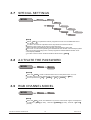
3.7
SPECIAL SETTINGS
MENU
S ET
U P Ld
PASS
R E ST
***
PASS
Sen d
***
En d
rEST
SET
Select UPLd to upload the custom programs from the current MASTER unit to
the SLAVE units.
In order to activate the upload function the password must be entered
Password is the same as the main access password
When uploading the MASTER and SLAVE units will display YELLOW
If an error occurs when uploading the MASTER and/or SLAVE units will display RED
On successful uploading of the custom programs the MASTER and SLAVE units
will display GREEN.
In order to reset custom modes to default values select rEST
3.8
A CTIVATE THE PASSWORD
MENU
PASS
On
OFF
PASS
Enter the PASS mode to select whether the access password is on or off.
In order to enter access password it is necessary to first press SET
Access password is UP + DOWN + UP + DOWN
3.9
RGB CHANNEL MODEL
MENU
ARC
RGb
RGb
Enter the RGb mode, the DMX512 only receive 3 channels' signal, the sequence
is channel 1 RED (0~255), channel 2 GREEN (0~255) , channel 3 BLUE
(0~255).
3 DISPLAY PANEL OPERATION
18
2007.03.10
4
USING A DMX512
CONTROLLER
4.1
4.2
4.3
BASIC ADDRESSING
CHANNEL ASSIGNMENT
BASIC INSTRUCTIONS FOR DMX512
OPERATION
4 USING A DMX512 CONTROLLER
19
2007.03.10
4.1
BASIC ADDRESSING
Connect all of the units in series using standard DMX512 signal cable or the IP65 rated cable
provided.
Set the DMX512 address in the DMX menu.
It is possible to have the same DMX address or independent addresses for each fixture.
4.2
CHANNEL ASSIGNMENT
DMX MODE
CHANNEL
VALUE
FUNCTION
1
2
3
0
255
MASTER DIMMER
0
255
0
255
(or FADE TIME when PR.01-PR.10 is activated)
0
255
BLUE
0
RED
(or STEP TIME when PR.01-PR.10 is activated)
GREEN
4
5
9
NO FUNCTION
10
29
RED
30
39
RED(85%)+YELLOW(15%)
40
49
RED(60%)+YELLOW(40%)
50
69
YELLOW
70
79
YELLOW(85%)+GREEN(15%)
80
89
YELLOW(60%)+GREEN(40%)
90
109
GREEN
110
119
GREEN(85%)+BLUE(15%)
120
129
GREEN(60%)+BLUE(40%)
130
149
BLUE
150
159
BLUE(85%)+CYAN(15%)
160
169
BLUE(60%)+CYAN(40%)
170
189
CYAN
190
199
CYAN(50%)+PURPLE(50%)
200
219
PURPLE
220
229
PURPLE(50%)+WHITE(50%)
230
249
WHITE(95%)+YELLOW(5%)
250
255
WHITE
0
6
4 USING A DMX512 CONTROLLER
9
NO FUNCTION
10
63
STROBE 1
64
127
STROBE 2
128
191
STROBE 3
192
255
STROBE 4
20
2007.03.10
CHANNEL
VALUE
0
7
FUNCTION
9
NO FUNCTION
10
19
AT. 01 ( AUTO 01 )
20
29
AT. 02
30
39
AT. 03
40
49
AT. 04
50
59
AT. 05
60
69
AT. 06
70
79
AT. 07
80
89
AT. 08
90
99
AT. 09
100
109
AT. 101 (AT.01 to AT.09 cycle 5min each AUTO mode)
110
119
PR.C1 (CUSTOM PROGRAM 1)
120
129
PR.C2
130
139
PR.C3
140
149
PR.C4
150
159
PR.C5
160
169
PR.C6
170
179
PR.C7
180
189
PR.C8
190
199
PR.C9
200
255
PR.10
ID ADDRESS
9
ID1~ID66
10
19
ID1
20
29
ID2
30
39
ID3
40
49
ID4
50
59
ID5
60
69
ID6
70
79
ID7
80
89
ID8
90
99
ID9
100
109
ID10
110
119
ID11
120
129
ID12
130
139
ID13
140
149
ID14
150
159
ID15
160
169
ID16
170
179
ID17
180
189
ID18
190
199
ID19
200
209
ID20
0
8
4 USING A DMX512 CONTROLLER
21
2007.03.10
CHANNEL
VALUE
8
ID21
211
ID22
212
ID23
213
ID24
214
ID25
215
ID26
216
ID27
217
ID28
218
ID29
219
ID30
220
ID31
221
ID32
222
ID33
223
ID34
224
ID35
225
ID36
226
ID37
227
ID38
228
ID39
229
ID40
230
ID41
231
ID42
232
ID43
233
ID44
234
ID45
235
ID46
236
ID47
237
ID48
238
ID49
239
ID50
240
ID51
241
ID52
242
ID53
243
ID54
244
ID55
245
ID56
246
ID57
247
ID58
248
ID59
249
ID60
250
ID61
251
ID62
252
ID63
253
ID64
254
ID65
255
9
4 USING A DMX512 CONTROLLER
FUNCTION
210
ID66
0
250
CH1, CH2, CH3 & CH4 INSTANT FADER RESPONSE
251
255
CH1, CH2, CH3 & CH4 DELAY FADER RESPONSE
22
2007.03.10
4.3
BASIC INSTRUCTIONS FOR DMX512
OPERATION
MASTER DIMMER
CH1 controls the intensity of the currently projected color
When the slider is at the highest position (255) the intensity of the output is the maximum
RED, GREEN & BLUE COLOR SELECTION
CH2, CH3 & CH4 control the intensity ratio of each of the RED, GREEN & BLUE LEDs.
When the slider is at the highest position (255) the intensity of the color is the maximum.
CH2, CH3 & CH4 can be combined together to create over 16 million colors.
CH2, CH3 & CH4 have priority over CH4, CH5, CH6 & CH7
COLOR MACROS
CH5 selects the required COLOR MACRO
CH5 has priority over CH2, CH3 and CH4
CH1 is used to control the intensity of the COLOR MACRO
STROBE
CH 6 controls the strobe of CH1 to CH5
Strobe 1 is with RGB in-step
Strobe 2 is with RGB out-step
Strobe 3 is a pulse strobe (slow on/fast off)
Strobe 4 is a pulse strobe (fast on/slow off)
ID ADDRESS SELECTION
CH8 is used to select the target ID address.
Each independent DMX address may have upto 66 independent ID addresses.
An ID address of 0 will activate all ID address locations.
AUTO
CH7 selects the preset AUTO programs AT.01-AT10 or the custom AUTO programs PR.C1PR.10
When activating the custom AUTO programs PR.C1 to PR.10 then it is possible to control the
STEP TIME and FADE TIME using CH2 and CH3 respectively.
CH9 is used to select whether the unit operates with an instant response to the DMX fader or
whether there is a preset delay response.
4 USING A DMX512 CONTROLLER
23
2007.03.10
5
USING THE CONTROLLER
5.1
5.2
5.3
5.4
5.5
5.6
5.7
5.8
5.9
5.10
MENU
WASH PROGRAM
EFFECT PROGRAM
CUSTOM PROGRAM
PLAY SCHEDULE
CLOCK
SCHEDULE
SETTINGS
ACTIVATE THE PASSWORD
PiX CONTROLLER EXTERNAL
CONTROL VIA DMX512
5.11 MAINTENANCE
5 USING THE CONTROLLER
24
2007.03.10
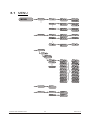
5.1
MENU
MENU
Wash program
Wash
Wash
Wash
Effect program
1
2
8
Wash
Edit
1
Wash
Edit
2
Wash
Edit
8
Step time
001
Fade time
001
Step time
001
Fade time
001
Step time
001
Fade time
001
Effect
1
Effect 1
Edit
Speed
001
Effect
2
Effect 2
Edit
Speed
001
Effect
8
Effect 8
Edit
Speed
001
Scene 1
ID address
Scene 1
ID address
Scene 1
Step time
Scene 1
Module 001
Scene 1
Fade time
Scene 1
Red 001
Scene
Red
1
Scene 1
Green 001
Scene
Green
1
Scene 1
Blue 001
Scene
Blue
1
Scene 1
Strobe 001
Custom program
Custom
1
Custom
Edit
1
Scene 1
Scene 2
Scene 100
5 USING THE CONTROLLER
Scene 1
Module
Scene
Scene 1
Strobe
Scene
Play schedule
Schedule
>>>
Clock
Time now
02/08/2006
13:50:24
Edit time
02/08/2006
13:50:24
25
1
Step time
Fade time
001
1
001
2007.03.10
Schedule
Settings
Password
5 USING THE CONTROLLER
26
Wash 1
00:00>>>00:00
Start >>> End
00:00 >>>00:00
Wash 2
00:00>>>00:00
Start >>> End
00:00 >>>00:00
Wash 8
00:00>>>00:00
Start >>> End
00:00 >>>00:00
Effect 1
00:00>>>00:00
Start >>> End
00:00 >>>00:00
Effect 2
00:00>>>00:00
Start >>> End
00:00 >>>00:00
Effect 8
00:00>>>00:00
Start >>> End
00:00 >>>00:00
Custom 1
00:00>>>00:00
Start >>> End
00:00 >>>00:00
Custom 2
00:00>>>00:00
Start >>> End
00:00 >>>00:00
Custom 8
00:00>>>00:00
Start >>> End
00:00 >>>00:00
DMX address
DMX address
001
Range
Range
001
Allow edit
Allow edit
YES NO
Detect device
>>>
Reset to
Factory settings
Reset
YES NO
Password ON/OFF
Password
ON/OFF
Set password
Set Password
2007.03.10
5.2
WASH PROGRAM
MENU
Wash program
Wash
Wash
Wash
1
2
8
Wash
Edit
1
Wash
Edit
2
Wash
Edit
8
Step time
001
Fade time
001
Step time
001
Fade time
001
Step time
001
Fade time
001
Wash
Select from the eight Wash programs and instantly play
When Edit is allowed in [Settings] it is possible to set the Step time
and Fade time
The unit of Step time is 5 seconds and can be adjusted from 1 to 255
The unit of Fade time is 5 seconds and can be adjusted from 1 to 255
5.3
EFFECT PROGRAM
MENU
Effect program
Effect
1
Effect 1
Edit
Speed
001
Effect
2
Effect 2
Edit
Speed
001
Effect
8
Effect 8
Edit
Speed
001
Effect
Select from the eight Effect programs and instantly play
When Edit is allowed in Settings it is possible to set the Speed
The Speed of the Effect can be adjusted from 1 to 255
5 USING THE CONTROLLER
27
2007.03.10
5.4
CUSTOM PROGRAM
MENU
Custom program
Custom
1
Custom
Edit
1
Scene 1
Scene 2
Scene 100
Scene 1
ID address
Scene 1
ID address
Scene 1
Step time
Scene 1
Module 001
Scene 1
Fade time
Scene 1
Red 001
Scene 1
Red
Scene 1
Green 001
Scene 1
Green
Scene 1
Blue 001
Scene 1
Blue
Scene 1
Strobe 001
Scene 1
Module
Scene 1
Scene 1
Strobe
Scene 1
Step time
Fade time
001
001
Custom
Select from the eight Custom programs and instantly play
When Edit is allowed in Settings it is possible to enter the edit section
Scene
Select from 100 scenes to create or edit
Scenes that are not required should have the Step time set as 0
ID address
Select the ID address of the target unit
Set the ID address as 0 to include all ID addresses
ID address action from previous steps is stored until changed allowing for
combination colors/effects using different ID addresses
Module
Select the [Module] to be active:
0=#1 #2 # 3
1=#1
2=#2
3=#3
4=#1 #2
5=#2 #3
6=#1 #3
Red , Green & Blue
Combine RED, GREEN & Blue to create an infinite range of colors (0-255)
Strobe
Select the strobe speed from 0-20Hz
Step time
Select the
The unit of
Step time of the current scene
Step time is 0.1s for the range 0-10 and 1 sec for the range 11-255
Fade time
Select the [Fade time] of the current scene
The unit of [Fade time] is 1 second and can be adjusted from 0 to 255
5 USING THE CONTROLLER
28
2007.03.10
5.5
PLAY SCHEDULE
MENU
Play schedule
Schedule
>>>
Schedule
Activate this menu in order to play the schedule
5.6
CLOCK
MENU
Clock
Time now
02/08/2006
13:50:24
Edit time
02/08/2006
13:50:24
Time now
Enter this function to view the current time.
Edit time
Enter this menu to edit the date and time.
5.7
SCHEDULE
MENU
5 USING THE CONTROLLER
Schedule
29
Wash 1
00:00>>>00:00
Start >>> End
00:00 >>>00:00
Wash 2
00:00>>>00:00
Start >>> End
00:00 >>>00:00
Wash 8
00:00>>>00:00
Start >>> End
00:00 >>>00:00
Effect 1
00:00>>>00:00
Start >>> End
00:00 >>>00:00
Effect 2
00:00>>>00:00
Start >>> End
00:00 >>>00:00
Effect 8
00:00>>>00:00
Start >>> End
00:00 >>>00:00
Custom 1
00:00>>>00:00
Start >>> End
00:00 >>>00:00
Custom 2
00:00>>>00:00
Start >>> End
00:00 >>>00:00
Custom 8
00:00>>>00:00
Start >>> End
00:00 >>>00:00
2007.03.10
Wash
, Effect
&
Custom
Enter each of the twenty-four Wash , Effect and Custom programs to
set Start & End time
Programs will be played according to schedule time order.
When a program is currently playing and has not yet reached the [End] time, any
new [Start] time will have priority when over-lapping times.
5.8
SETTINGS
MENU
Settings
DMX address
DMX address
001
Range
Range
001
Allow edit
Allow edit
YES NO
Detect device
>>>
Reset to
Factory settings
Reset
YES NO
DMX address
Enter the DMX address menu to set the DMX address of the controller.
The DMX address may only be selected in the range 1-250
Range
Enter the number of units connected together in series.
Allow edit
This function allows or disables edit in Wash program ,
Effect program & Custom program
Detect device
This function enables the controller to connect to all units.
When new units are attached, this function must be used to locate new units.
When the controller is turned off and then on again, the controller will also
detect new units.
Reset to factory settings
This functions will reset all settings to the original factory setting.
Note that Custom program settings will not be affected by this function
Default settings
Schedule all times in the schedule are reset to 00:00
Wash program step times and fade times are reset to 001
Effect program speeds are reset to 001
DMX address DMX address is reset to 001
Range range is reset to 066
Allow edit allow edit is reset to Yes
Password ON/OFF password is reset to OFF
Set password password is reset to 00000000 ('DOWN’ = 0, 'UP' = 1)
5 USING THE CONTROLLER
30
2007.03.10
5.9
ACTIVATE THE PASSWORD
MENU
Enter the
Passw ord
O N / OF F
Password
ON/OFF
Set Password
Password
Password mode to set password YES/NO
When password is activated, display will demand password each time
the fixture is powered on.
Enter the Set password menu to change password.
Set new password using the UP & DOWN keys.
Input an 8 digit password and then press SET to confirm
NOTE: In the event that the password is forgotten. Please use the factory password shown below.
UP > DOWN > UP > DOWN > Up >UP > DOWN > DOWN
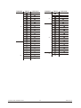
5.10
PiX CONTROLLER EXTERNAL
CONTROL VIA DMX512
It is possible to access the internal programs of the PiX controller using a DMX512 controller.
The diagram below shows how to connect the equipment together.
It is necessary to set the DMX address on the controller to the target
DMX address as selected on the DMX512 controller
DMX512
CONTROLLER
CONTROLLER
MO DE
5 USING THE CONTROLLER
31
S ETUP
UP
D OWN
2007.03.10
CHANNEL
VALUE
FUNCTION
151
160
Refresh
11
30
Wash 1
161
180
Effect
31
40
Refresh
181
190
Refresh
41
60
Wash 2
191
210
Effect
61
70
Refresh
211
220
Refresh
90
Wash 3
221
255
Effect
100
Refresh
2
6
7
8
0
10
Refresh
101
120
Wash 4
11
30
Custom 1
121
130
Refresh
31
40
Refresh
131
150
Wash 5
41
60
Custom 2
151
160
Refresh
61
70
Refresh
161
180
Wash 6
71
90
Custom 3
181
190
Refresh
91
100
191
210
Wash 7
211
220
Refresh
221
255
120
Custom 4
121
130
Refresh
Wash 8
131
150
Custom 5
151
160
Refresh
161
180
Custom 6
0
10
Refresh
30
Effect
31
40
Refresh
41
60
Effect
61
70
Refresh
71
90
Effect
100
Refresh
101
11
91
5 USING THE CONTROLLER
VALUE
Refresh
71
2
CHANNEL
10
91
1
FUNCTION
0
3
1
181
190
Refresh
2
191
210
Custom 7
211
220
Refresh
3
221
255
Custom 8
Refresh
101
120
Effect
121
130
Refresh
131
150
Effect
4
4
0
128
127
255
OFF
ON
5
32
2007.03.10
5.11
MAINTENANCE
No
ITEM
1
Gel holder
2
Upper cover
3
Glass plate
4
LED heat-transfer plate
5
Power supply
6
Display board
7
Casing
8
Driver board
9
Secondary support
10
1
2
3
4
Main support
5
6
7
8
9
10
5 USING THE CONTROLLER
33
2007.03.10


![[Federal Register: April 12, 1999 (Volume 64, Number 69)]](http://vs1.manualzilla.com/store/data/005742852_1-e5ad3fd67c2402334828f9fc4efc3f1c-150x150.png)