1
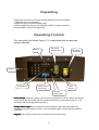
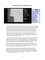
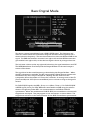
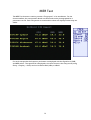
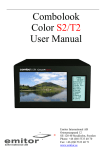
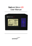
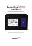
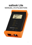
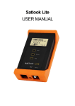
Satlook Color HD User Manual SATLOOK COLOR HD Ostmastargrand 12 120 40 Stockholm, Sweden Phone: +46 8 5333 40 70 Fax: +46 8 5333 40 71 www.emitor.se Thank You for purchasing the Emitor AB Satlook Color HD instrument. This manual covers the operation and maintenance of the Emitor AB Satlook Color HD instrument used for satellite dish alignment and signal analysis. All information in this publication is based on the latest product information available at the time of printing. Emitor AB reserves the right to make changes at any time without notice and without incurring any obligation. No part of this publication may be reproduced without written permission. This manual should be considered a permanent part of the instrument and should remain with it if the instrument is resold. If a problem should arise, or if you have any questions about the instrument, consult an authorized Emitor AB dealer. Notice Operating the Satlook Color HD instrument requires special skills. Please read this User Manual thoroughly before operating the instrument. 2 Updated: August 1, 2013 Contents Overview 4 Unpacking 6 Operating Controls 6 LCD 8 Remote Control 9 Basic Spectrum Operation 10 Basic Digital Mode 12 Digital Mode Functions 13 MER Test 14 Digital Picture Mode 15 Memory 17 Text Editor 17 DiSEqC 18 Setup 19 Special Functions 20 UniCable LNB Functions 21 Using PC to transfer transponder data Load Firmware 24 25 Appendix A – Universal LNB Primer Appendix B – DiSEqC Primer Appendix C – DVB-S and DVB-S2 Primer Appendix D – UniCable Primer Appendix E – Maintenance Appendix F – Specifications Glossary 27 28 30 31 33 34 35 3 Overview The Emitor Satlook Color HD is a Swedish designed spectrum analyzer and satellite television measuring instrument. The Satlook Color HD was engineered for the precision alignment and adjustment of satellite dishes. This instrument was designed for the professional when accurate and precise information is needed. With ease of operation through powerful processor technology, basic operation is achieved with only a few controls. The functions are easy to access and only take minutes to learn. Many functions can be controlled by the enclosed Remote control. A 5 inch 16:9 color TFT-LCD display is provided which shows either normal “Free to air” satellite TV channels in DVB-S, the frequency spectrum 950-2150 MHz, or a Constellation diagram and digital information regarding the signal. Menus and help displays are shown on the LCD screen (64x128) beside the monitor and a keypad is used for the function selection. The knob is used for frequency and other operations. A remote control is provided which allows most of the commands to be used. The Spectrum Mode enables the measurement of the satellite spectrum in resolution steps of 1 MHz to 10 MHz making it easy for the skilled installer to know what satellite he is receiving and make more detailed measurements. The Spectrum function spans the frequency band 920-2150 MHz and can be expanded from 4 MHz down to 1 MHz steps. Cross polarization at a frequency can be easily checked with the cross polarization function. The instrument has high resolution for accuracy. It presents measured data ±2 dB (at 20o C). Frequency tuning is done with the main knob in frequency steps between 4 MHz and 1 MHz depending on the span of the spectrum. When the spectrum is displayed, Automatic Spectrum Identification is provided by accessing the NIT information by hunting for a DVB-S signal from one of the transponders. The Digital Mode shows extended information of Modulation, SIG, SNR, BER, MER, and a constellation diagram. The Satellite Name and position are shown using the Network Information Table in the MPEG transport stream. Channel detail (or Service Information) can also be displayed for a transponder if needed. The user memory positions can save spectrum displays, analog channels, digital channels and Saved spectrum positions can be mixed simultaneously with an actual reading for easy comparison and control of signal-levels. Measurements on group of channels can be made with up to 10 frequencies simultaneously with automatic polarization and band selection. For Universal LNBs, the polarisation V/H is switchable by 13/18V and Lo/Hi band with 22 kHz-tone. The instrument features circuitry protection to prevent short circuits during connection of the LNB. The DiSEqC function controls all DiSEqC accessories such as switches and positioners. 4 The Satlook Color HD is powered by a built- in, rechargeable Li-Ion battery. The battery can be recharged using either the included external battery charger or the car-adaptor. The Satlook Color HD weighs less than 3kg including the battery and the carrying case. 5 Unpacking Unpack the instrument and check that the following items are included: 1. Satlook Color HD instrument. 2. Nylon carrying case with shoulder strap. 3. Power supply and charger 110-230VAC /14 VDC, center pin positive 4. Auto Adapter cord (Car charger) 12V. Operating Controls The side view of the Satlook Color HD is shown below with the operating controls indicated. Video and Audio Output RS232 RF Input from LNB Keypad Tuning Knob Audio Volume and Tuning Power Switch Charger Power input from charger Power Switch) Switch) On battery power, this turns the instrument on and off. When the charger is connected, the instrument will charge with the switch off, and operate when on. The instrument will not charge when operating. Charger Power Input) The instrument can be charged or operated using either the supplied 14V power supply or from a 12V car cigarette lighter plug using the supplied connector. Keypad) This is used to select most of the functions from the menu. 6 RF Input from LNB) This is the LNB input. It supplies 13V/18V and the 22kHz signal when required. Audio Volume) The audio volume can be adjusted for either the Digital or Analog reception. Audio Tuning) This can tune the Audio passband from 5.5 MHz to 8.5 MHz for Analog TV reception. Tuning Knob) This knob is used for frequency selection and other functions. The knob includes a push button that is used for selection. In the Spectrum mode, the tuning knob is used for frequency adjustments, bandwidth (span) adjustments and signal Offset level. The knob button is used to change the mode. In the Digital Picture mode, the knob is used to select the next picture, and for memory selections. In the Analog Picture mode, the knob is used for frequency selection and for memory locations. In the Digital mode, the knob is used for frequency selection and memory selection. RS232) This port is used for firmware updates and updates of channel information. Video and Audio Output) The video and audio signal can be output to another device for viewing. 7 LCD The LCD window shows the current functions available using the keypad or remote. For each function, the keypad number is shown to the left. Also shown is the current status of the LNB, the knob operation mode, and the battery/external power. Shown below is the LCD display in the Spectrum mode. Turning the knob will adjust frequency LNB power 13V or 18V Battery state or power supply connected Enter Digital Mode using the keypad ‘2’ Switch the LNB 13V/18V using the keypad ‘0’ Switch the LNB 22kHz signal on or off using the keypad ‘#’ When the operation can use a memory location, the lower portion of the LCD shows the current memory selection. For this case, the knob is used to change the memory position number that the ‘Save’ will use. Turning the knob will select the memory location Memory position and name 8 Remote Control Power Not used Used same as keypad entry Exit Used for keypad ‘#’ which is 22kHz control to select band Open TV or Radio channel Next channel Previous channel 9 Basic Spectrum Operation The Spectrum Mode is displayed when the instrument is turned on. With a dish and LNB connected, it will show a display similar to that above. The spectrum is displayed with the Start frequency at the top of the screen and the Stop frequency at the bottom. The Span is the total frequency coverage or the difference between Stop frequency and Start frequency. The current signal level (14.3 dBmV in this example) is displayed for the frequency at the Marker. The knob is used to change this to the frequency of interest. When Spectrum Mode is entered, the peaks are checked to see if the demodulator can lock. If a lock occurs, the NIT data for the transponder is displayed for automatic satellite identification. NIT data on a transponder is repeated at least every 10 seconds and on most satellite more often than this. The span of the Spectrum can be changed in two ways. Pressing the keypad ‘3 Span’ will change the spectrum to the minimum span of 250MHz. For this span, each division is 1MHz. An alternate method is to use the adjustable span. Pressing the knob allows the span to be adjusted from a minimum of 250MHz to the maximum of 1231MHz. At this maximum span, the entire IF band from 920MHz to 2150MHz is displayed. When span is adjusted by pressing the knob, a second press of the knob allows the “DC Offset” of the spectrum to be adjusted for best display. A further press of the knob restores the operation to frequency adjustment. The span setting from the knob remains as the current setting. The “DC Offset” is restored to 0. The current band being displayed can be changed with the 22kHz signal using the keypad ‘# 22kHz’. For Universal LNBs, when the 22kHz is off, the band is Lo Band (920MHz to 11900MHz) and when the 22kHz is on, the band is Hi band (11520MHz to 2150MHz) There is a small overlap from 11520MHz to 11900MHz, so a Universal LNB can tune this range with 22kHz either on or off. . 10 Picture) Allows the display of Analog or Digital channels. (see Analog Picture Mode page 16 or Digital Picture Mode page 14) Digital) Changes to Digital mode at frequency of marker. Span Min/Max) Changes the spectrum bandwidth fro 250MHz to 1231MHz. X-Pol) Performs a cross polarisation check at the marker (or nearest peak) and displays the result at the lower right of the TFT. DiSEqC) See DiSEqC on page 18. Setup) See Setup on page 19. Beeper) The Beeper function is enabled or disabled and can be used to provide an audio signal of the signal level at the marker position. Spec) See the Special Spectrum functions on page 21. Memory) This allows saving or mixing the Spectrum with saved spectrum pictures. See the Special Spectrum Mix on page 21. 13/18V) Switches the LNB voltage between 13V and 18V. 22kHz) Switches the LNB 22kHz signal which switches between Lo band and Hi band for Universal LNBs. 11 Basic Digital Mode This shows a typical constellation from a DVB-S QPSK signal. The frequency and offset are shown below the constellation diagram and the measured symbol rate is shown below the frequency. The two thermometer bars show the BER and SNR of the signal. The SNR thermometer increases from right to left and the BER thermometer gets smaller from right to left, so that the best signal is shown by a longer white bar. The lock time is shown at the top right and below this, the signal modulation and FEC. The MER (Modulation Error Ratio) and the Output Bit Rate for the total transport stream is also shown. The signal level at the tuned frequency is shown below the Output Bit Rate. When the NIT information is available, the NIT name and NIT Orbital Position appear with the Network ID, and Transport Stream ID. Reading the SDT data from the transponder shows the number of “Free to Air” channels. A running count of the CB (Corrected Bit) and UCB (Uncorrected Block) errors is shown as long as the signal is locked. For DVB-S QPSK signals, the BER = ErrorpreViterbi/(BitRate TimeLock). For DVB-S2 QPSK or 8PSK signals, this is pre-LPDC BER and is estimated from SNR using the relation shown in the glossary under BER. It is recommended to use SNR for DVB-S2 optimization. When the modulation is DVB-S2 8PSK, the constellation is shown with target boxes overlayed. They may appear in two orientations as shown below. The target boxes will move to the ideal positions for the 8PSK Constellation presentation. 12 Digital Mode Functions Search +/+/-) A signal search can be initiated by using the keypad ‘1 Search +’ to search with increasing frequency or ‘2 Search –‘ with decreasing frequency. The search mode moves to the next peak in the spectrum and attempts a lock for DVB-S QPSK, DVB-S2 QPSK and DVB-S2 8PSK signals. The symbol rate is determined automatically. Because the time to lock for low symbol rate signals increases the lower the symbol rate, symbol rate signals below about 16000 will not lock during a search. Memory) Frequencies are stored in the Digital memory. (see Memory page 13) Channels) When a signal is locked, the Digital services from the SDT Service Information will be displayed on the TFT screen. DiSEqC) DiSEqC) DiSEqC commands can be initiated. (See DiSEqC page 18) Beeper) Enables or disables the Beeper at the frequency. 13/18V) Switches the LNB voltage between 13V and 18V. 22kHz) Switches the LNB 22kHz signal which switches between Lo band and Hi band for Universal LNBs. Exit) Returns to the Spectrum display. 13 MER Test The MER Test function is used to provide a ”Fingerprint” of an installation. For the chosen satellite, four transponder details are shown and can be photographed for a permanent record. Each transponder is tuned and the values are displayed when they are stable. For each transponder the frequency and name are displayed with the Signal Level, SNR, and MER values. The signal level is displayed in the units chosen in the setup menu (using Setup -> Display -> Units) and can be either dBuV, dBm, or dBmV. 14 Digital Picture Mode From the Digital display, when the input frequency is locked and the modulation type displayed, the SDT data can be examined using the Channels function with keypad ‘4 Channels’. This shows a list of the services on the transponder. Encrypted channels are shown in RED and cannot be selected. The current selected channel is shown in WHITE. FTA channels are shown in GREEN and radio channels are shown in YELLOW. When there are FTA channels available, the current selected channel can be opened by keypad ‘3’. Using the keypad ‘3 Open’ shows the selected picture or if a radio channel plays the audio. 15 More details are available using the keypad ‘4 SNR Info’ function or the keypad ‘5 Pic Info’ functions. 16 Memory Functions There are three different user memory types in the Satlook Color HD instrument. They are divided according to the type of data storage required. Each memory area is chosen automatically depending on the type of data. Spectrum Memory: There are 100 memory positions reserved for User data of the spectrum waveforms. This data can be loaded and viewed or mixed with the current signal for comparison. Digital Memory: There are 100 memory positions reserved for User data of Digital frequencies. Each position stores the Name, frequency, 13/18V, and 22kHz state. Digital Channel Memory: There are 100 memory positions reserved for User data of Digital Channels. Each position stores the Name, Service ID, frequency, 13/18V, and 22kHz. Text Editor All the User memory areas use the Text Editor for saving the name for the memory position. With the Digital Channel memory, the current channel name is entered from the SDT data and usually this name is correct and all that is required is to save the name. With the other memory positions, a name requires manual entry. Use the knob to select the characters from the list and the knob select button to enter the character. Characters can be deleted by using the keypad ‘1 Delete’ and the current position can be changed by the keypad ‘2 Left’ or ‘3 Right’. The keypad ‘* Save’ completes the entry and saves the name to the memory position. 17 DiSEqC Functions The Satlook Color HD instrument supports all usual DiSEqC commands for the DiSEqC specifications 1.0, 1.1 and also supports the Goto X function for easy positioner movement. The DiSEqC commands can be accessed from several menus for convenience. From the Spectrum Mode: keypad ‘5 DiSEqC’ From the Digital Mode: keypad ‘5 DiSEqC’ From the Multichannel Mode: keypad ‘ 8 Spec’, keypad ‘5 MultiCH’, keypad ‘5 DiSEqC’ In the DiSEqC menu, the DiSEqC commands LNB1, LNB2, LNB3, LNB4 as well as Tone Burst A and Tone Burst B can be sent. For Switches, the SWx command allows the switch commands SW1 up to SW16 to be sent. The Motor command allows the operation of positioners. Go East and Go West move the positioner as long as the key is pressed. Calibrate moves the positioner to the home position, usually due south. Limits allow “soft” limits to be set or cleared for the positioner. Position allows the setting a movement to defined positions, The Go East command and Go West command are used to move the positioner to an optimum position, and then that position is saved from 1 to 31. (Goto position 0 commands the positioner to its home position.) The Goto X (also called USALS) command removes the necessity to find positions manually. To use the Goto X function, the instrument latitude and longitude must be known. Once these are set, they are stored in permanent memory and so will not be lost on power down. Once the latitude and longitude are correct, the positioner can be commanded to move directly to a satellite orbital position. 18 Setup The Setup menu contains the functions which are used during setup. LNBLO) LNBLO) The LNB type can be selected in this menu. The LNB local oscillator down converts the satellite frequency (10670MHz to 12750MHz) to the intermediate frequency ( 920MHz to 2150MHz). If no conversion is desired, the IF setting is used. Analog) Analog) The default for the Analog Picture inversion can be set here. Normal is used by Ku Band and Invert is used for C Band. Motor) Motor) The positioner type can be set here. The most common positioner type is DiSEqC (Dis 1.2) and the other types supported are Satsel and Satscan. Display) Display) The display units for signal level can be set to dBuV, dBm, or dBmV. The LCD contrast can be adjusted and the LCD backlight enabled or disabled. The Spectrum Graticule can be turned on for dB guidelines. AutoOff) AutoOff) AutoOff can be set to turn the unit off automatically after a number of minutes if no knob of key actions occur. AutoOff does not operate when on external power. Version) Version) The version menu displays serial number, levels of the firmware and related information. KeyClick KeyClick) ick) The beep for a keypress can be enabled or disabled. Knob Dir) The direction of movement for the knob can be changed for frequency adjustments and for other functions such as selecting the displayed picture. The default is clockwise rotation of the knob is increasing frequency and moves the onscreen selection down. 19 Special Functions MaxHold) This sets the measurement of signal level to hold and display the maximum received values. Once enabled, the measurements will remain in MaxHold until expressly disabled. Refmrkr) The Reference marker allows a second marker to be placed on the spectrum display. Adjust the marker to the required second location and set the reference marker. Now when the marker is moved to another location on the spectrum display, the difference in dB level and the frequency difference are displayed. Span Min/Max) The span can be changed when on this menu for convenience. It is the same as the span setting on the Spectrum menu. Memory) Samples of spectrum data can be saved in memory and then either displayed or mixed with the current spectrum. When the mix function is chosen, the current spectrum is adjusted to the same span and starting frequency, and then the spectrum from memory is overlayed as a line image so that you can compare the current signal with a saved spectrum. The spectrum memory is selected using the knob and the memory position is displayed on the TFT. Spectrum memory can be loaded for examination as well as mixed. Atten) The 15dB attenuator can be inserted or disabled from this menu. 13/18V) The 13V/18V LNB voltage can be changed at this menu for convenience. 22kHz) The 22kHz LNB signal can be changed at this menu for convenience. 20 UniCable (Sat-CR) LNB Functions When a UniCable LNB is first connected, there will be no signal. This is because in the Spectrum mode, no UniCable commands are issued. Command the UniCable LNB by switching to the Digital mode and back to the Spectrum mode and it will show a spectrum. (Turning on and off the LNB 13/18 or the LNB 22kHz will also command a UniCable frequency.) The span of the spectrum can be set to either 250MHz or 1231MHz (the maximum or minimum) by pressing the keypad ‘Span’. The Marker frequency shows the IF frequency of the User Band. The translated UniCable signal will be at the chosen User Band and about 100MHz wide. For the UniCable LNB, the LNB 13V/18V and the LNB 22kHz signal represent the Polarisation and the Band and are not sent to the UniCable LNB. In the Digital mode, the frequency shown is the UniCable commanded frequency. Remember that the displayed UniCable band is reflected in frequency about the User Band frequency as shown in the example below. For more details see Appendix D. User Band 1 10936 MHz 10906 MHz 10878 MHz 21 When the SatCR (UniCable) is chosen as the LNB, the options to be used can be selected. UsrBnd) Selects the number of User Bands to be 4 or 8. For LNBs, it is usually 4, and may be 8 for switches. Use UB1) The User Band to be used for tuning can be selected. Set UB) The individual User Band frequencies can be adjusted to suit the LNB under test. These are saved during power off. Set Def) This resets the User Bands to the default values. The defaults for 4 User Bands are 1210, 1420, 1680, 2040 and for 8 User Bands are 1284, 1400, 1516, 1632, 1748, 1864, 1980, 2096. Uni Test) The SatCR test allows full testing of a SatCR LNB. This test takes about 20 seconds to check each User Band. During the test, the four User Bands are identified. At the end of the test, the results of measuring the User Bands are presented. 22 23 Using PC to transfer transponder data Satellite transponder data can be loaded from the instrument to and from a PC for easy changes. The Windows PC program used is chedit.exe. From the File Menu, a channel file can be loaded from the Combolook, edited and saved back to the Combolook. Also channel files can be loaded and saved on the PC for backup and easy updates of channel files. 24 Loading Firmware Loading new firmware to the Satlook Color HD is done using a Windows loader program called “FDLDVB.exe”. Also needed is the firmware hex file to load. The main control firmware will have a name like “ SC-HD-34”. Usually it will be necessary to only update the main control firmware. Do not load any firmware without these types of names, it will be for a different instrument and will not work on the Satlook Color HD. Use the Version screen in the Setup Menu to determine the current software versions. The firmware loading must be performed using the external charger. The USB to RS232 cable to be used is supplied as part of the kit with the Satlook Color HD. Connect the Rs232 cable from the computer to the instrument. Run the firmware download file “FDLDVB.exe”. Select the RS232 port on the computer. Normally, the port is COM1 but sometimes the USB to RS232 adapter will use some other port. If desirable, this USB to RS232 adapter can be made to always use COM1 by clicking Control Panel / Device Manager / Ports and in the Advanced settings for the adapter set to COM1. Select “Send Satlook Firmware” and then “OK” and the display will show “Searching”. Connect the Satlook Color HD to the external charger and the display will change to a file dialog to choose the firmware file. 25 Normally, the firmware will be in the same directory as “FDLDVB.exe” but if not, you can navigate to the correct directory and select the firmware file. Once the file is selected, the firmware loading will take about 11 minutes and then the Firmware Downloader program will display “Download Complete”. 26 Appendix A – Universal LNB Primer The LNB (low noise block amplifier) has evolved since its early introduction in Satellite broadcasting. Signals broadcast from satellites are 10600 MHz to 12700 MHz for Ku band and 3000 MHz to 4500 MHz for C band. Because the losses in coax are quite high for these frequencies, the satellite signal is first downconverted to a more manageable 950 MHz to 2150 MHz for transmission from the dish to the receiver. This is called the IF (intermediate frequency) or also the L Band. Most of the European broadcasting is in the Ku band. The satellite transmission can use either horizontal or vertical polarisation. This is a way of re-using the available spectrum since there can be two transponders at the same frequency with different polarisations. The Universal LNB can receive either horizontal or vertical polarisations depending on the LNB line voltage. 13V is used to select Vertical polarisation and 18V is used to select Horizontal polarisation. The Ku band for satellite reception is 2100 MHz wide (12700 – 10600) while the receiver input is only 1100 MHz wide (2150 – 950). To allow the full reception of the entire Ku band, two different local oscillator (LO) frequencies are used in the Universal LNB. This LO frequency is switched in the Universal LNB by using the 22 KHz tone. When it is off, then the LO frequency used is 9750 MHz and when on, 10600 MHz is used. The four frequency ranges for the Universal LNB are sometimes called quadrants and is diagrammed below showing the overlap. 13V Vertical 22 KHz Off Low Band 10700V MHz 13V Vertical 22 KHz On Hi Band 18V Horizontal 22 KHz Off Low Band 18V Horizontal 22 KHz On Hi Band 11900V MHz 11550V MHz 10700H MHz 12750V MHz 11900H MHz 11550H MHz 27 12750H MHz Appendix B – DiSEqC Primer About DiSEqC DiSEqC is an acronym for “Digital Satellite Equipment Control” and is achieved using the 22kHz signalling tone. The 22 kHz signal is imposed on the LNB DC voltage of 13V or 18V at a level of 0.65V p-p. Normally, the 22kHz signal is either continuously on or off. When a DiSEqC message is to be sent, if the 22kHz is on, it is turned off for a “quiet period” before the message. Then the DiSEqC message is sent as a series of bytes with an odd parity bit appended. The bits are formed by modulation of the 22kHz signal as shown below. Most DiSEqC commands are 3 bytes in length but some can be up to 6 bytes long, so the transmission time of a DiSEqC message is on the order of 40 to 80 milliseconds. DiSEqC Commands LNB1: 0xe0, 0x10, 0x38, 0xc0 LNB2: 0xe0, 0x10, 0x38, 0xc4 LNB3: 0xe0, 0x10, 0x38, 0xc8 LNB4: 0xe0, 0x10, 0x38, 0xcc SW1: 0xe0, 0x10, 0x39, 0xf0 SW2: 0xe0, 0x10, 0x39, 0xf1 SW3: 0xe0, 0x10, 0x39, 0xf2 SW4: 0xe0, 0x10, 0x39, 0xf3 SW5: 0xe0, 0x10, 0x39, 0xf4 SW6: 0xe0, 0x10, 0x39, 0xf5 SW7: 0xe0, 0x10, 0x39, 0xf6 SW8: 0xe0, 0x10, 0x39, 0xf7 SW9: 0xe0, 0x10, 0x39, 0xf8 SW10: 0xe0, 0x10, 0x39, 0xf9 SW11: 0xe0, 0x10, 0x39, 0xfa SW12: 0xe0, 0x10, 0x39, 0xfb SW13: 0xe0, 0x10, 0x39, 0xfc SW14: 0xe0, 0x10, 0x39, 0xfd SW15: 0xe0, 0x10, 0x39, 0xfe SW16: 0xe0, 0x10, 0x39, 0xff TBA: Tone Burst 0 to select satellite A TBB: Tone Burst 1 to select satellite B Go East: 0xe0, 0x31, 0x68, 0x1e Go Home: 0xe0, 0x31, 0x6b, 0x00 Go West: 0xe0, 0x31, 0x69, 0x1e 28 Set East: 0xe0, 0x31, 0x66 Clr Lim: 0xe0, 0x31, 0x63 Set West: 0xe0, 0x31, 0x67 Goto Pos: 0xe0, 0x31, 0x6b, <Position Number 1 to 31> Save Pos: 0xe0, 0x31, 0x6a, <Position Number 1 to 31> Goto X: 0xe0, 0x31, 0x6e, <Movement High Byte>, <Movement Low Byte> For the full DiSEqC specifications, see http://www.eutelsat.com/satellites/4_5_5.html) 29 Appendix C DVB-S and DVB-S2 Primer DVB-S and DVB-S2 both use phase shift keying to digitally modulate a carrier. Quadrature phase shift keying is used in both and the digital data is encoded as a 90 degree phase shift in the signal. This gives 4 possible states for each sampling interval. The sampling interval is called the Symbol Rate and each state of 2 bits is a Symbol. During transmission, this data is interleaved to allow recovery during noise bursts and redundant data is added called FEC (forward error correction). During reception, the data is re-shuffled to restore the order and the FEC data is used to correct the bitstream as necessary. In DVB-S2, 8PSK (octal phase shift keying) can be used in transmission where there are 8 possible states from a 45 degree phase shift in the Analog signal. A different scrambling and FEC for DVB-S2 allows better noise immunity. The bitstream output for both DVB-S and DVB-S2 is the same. This bitstream is called “transport stream”. A transport stream is made up of packets. All packets are the same length of 188 bytes and they all start with the sync byte 0x47 so that when the data is read, a starting point can be located. Each packet also contains a PID (packet identification). The information in the transport stream consists of several video and audio streams and also SI tables (Service Information) to allow the receiver to decode and display the correct data. There are several types of tables in the SI called PSI data. This table data is generally longer than one packet so several packets are assembled together to make a “section” which can be up to 1024 bytes. 1) Program Association Table (PAT): for each service in the multiplex, the PAT indicates the PID of the corresponding Program Map Table (PMT). It also gives the location of the Network Information Table (NIT). 2) Program Map Table (PMT): the PMT identifies and indicates the PIDs of the video, audio, and other streams that make up each service. 3) Network Information Table (NIT): the NIT gives the Network Number, Name and Satellite Position of the satellite. It also lists all the other transponders on the satellite. 4) Service Description Table (SDT): the SDT gives information about each service in this transport stream. Once these tables are decoded by the receiver, the correct PID for the audio and video streams can be found and presented to the video and audio decoders. In DVB-S, the video streams are presented in MPEG-1 or MPEG-2 encoding (usually MPEG-2). For DVB-S2, the video streams can be presented in these formats or in the newer HD format MPEG-4. (For a more complete understanding, see ISO 13818-1 “Information technology, Generic coding of moving pictures and associated audio information: Systems” and DVB EN 300 468 “Specification for Service Information”) 30 Appendix D UniCable Primer UniCable or SCIF (Single Cable Interface) is a method of translating Satellite frequencies from the LNB to the user. It is intended to allow multiple receivers to share the same coaxial cable. With a standard Universal LNB, with Horizontal and Vertical polarity and low and high band, there are four frequency ranges that can be selected from the LNB by using the 13V/18V and the 22kHz signal. In order to allow multiple receivers to operate using a single coax cable, UniCable operation requires the receiver to send the desired frequency using a DiSEqC command. A UniCable LNB or Switch may be used. For a UniCable Switch, the LNB input is usually a Quattro LNB which provides the four frequency ranges to the switch. For a UniCable LNB, the Switch and the Quattro LNB are integral. To tune a frequency on the UniCable LNB (or Switch), the receiver issues a DiSEqC command which indicates the Satellite Frequency needed, the Polarisation, the Band and what User Band to use. The number of User bands differs but normal is 4 or 8. The User Bands which are available can be determined by sending a DiSEqC command to emit RF tones at the centre frequencies of the User bands. By scanning the frequencies, the User Bands are located. To find out what number User Band this is, another DiSEqC command is sent to turn off the tone at User Band XX. By selectively turning the RF tones off, the number of the User Band is determined. Alternatively, The User Band Frequency allocation is usually provided on the LNB/Switch description. The placement of the User bands within the spectrum is not the same between manufacturers. For further detail on UniCable, see the specification EN 50494 – Satellite signal distribution over a single coaxial cable in single dwelling installations. 31 UniCable Commands: (only the 5 byte commands are shown) ODU_Power_OFF: (0xe0 0x00 0x5a D1 0x00) Turn power off for the selected User Band. D1 is defined as bit 5,6,7 select the User Band and bit 0,1,2,3,4 = 0; ODU_UBxSignal_ON: (0xe0 0x00 0x5b 0x00 0x00) Generate an RF tone at the centre of each User Band. ODU_Config: (0xe0 0x00 0x5b D1 D2) D1 is defined as bit 5,6,7 select the User Band and bit 0 = 1, bit 1,2,3,4 = 0; Generate an RF tone answer at the selected User Band for the question in D2 ODU_LoFreq: (0xe0 0x00 0x5b D1 D2) D1 is defined as bit 5,6,7 select the User Band and bit 1 = 1, bit 0,2,3,4 = 0; Generate an RF tone answer at the selected User Band for the question in D2 ODU_Channel_change (0xe0 0x00 0x5a D1 D2) D1 is defined as D1 is defined as bit 5,6,7 select the User Band, bit 3 selects polarisation, bit 2 selects low/high band, bits 0,1 of D1 and D2 are 10 bit Tuning Word. TuningWord = (FSatellite − FLO + FUserBand ) / 4 − 350 32 Appendix E- Maintenance The instrument is equipped with a rechargeable battery and it is important that the battery is maintained. Recharging should be done using the included car adaptor or external power supply. (110-220V/14V DC, center-pin positive and chassis earth) Please note that instrument can be operated, for shorter periods of time, by the external power supply, however, the Satlook Color HD is not made for permanent operation with the external power supply. This will degrade the battery. Contact your dealer for more information. Adjustments for vertical hold, brightness and contrast are located under the instrument. Contact your dealer for proper adjustments. The battery needs recharging when the battery symbol at the top of the LCD appears empty. Remember that a cold battery has much lower capacity than one at room temperatures. The Satlook Color HD is designed for outside use in rough conditions but it should not be exposed to rain or snow as this can damage or shorten the lifetime of the instrument. Checking/charging the battery: Because the instrument has been stored for some time before transportation it is important to check the battery-condition. To do this turn the main switch On. When starting the instrument, the LCD color monitor and LCD display turns On. There is a battery symbol at the top of the LCD display that shows the status of the battery. All black means that the battery is fully charged. If the symbol is empty it means that the battery is nearly completely discharged. If the battery needs recharging, use the power supply included with the instrument. A thermometer scale (0-100%) is displayed on the LCD as the recharging starts. Please note that the instrument should be turned off when being recharged. Charging will not be performed with the instrument is on. Recharging from fully discharged battery to about 98% capacity takes approximately 30 hours. When the battery been recharged the Satlook Color HD is ready to be used. 33 Appendix F – Specification Input frequency: 920-2150MHz Spectrum bandwidth from 250MHz to 1230MHz Frequency display: Yes, IF default. All standard LNB LO can be used Min level in, About 35 dBuV (noiselevel). Max level in, About 90 dBuV. Attenuation: 15 dB manual attenuator on/off. Display of signal level (Analog): dB-level on Spectrum display Pitch-tone on loudspeaker for dish signal strength optimisation Accuracy: +2 dB (at +20 C) Display of signal level (Digital): SNR (signal/noise-ratio), BER (bit error rate), MER Constellation diagram (DVB-S, DVB-S2, QPSK, 8PSK normal, 8PSK rotated) Symbol rate display: 1 to 45 MSymbols/sec Satellite identification: Yes, NIT display (Network Information Table) according to the DVB standard. Identifies Satellite Name and position. Name of TV and radio channels from SDT (Service Description Table) Analog TV/Audio standard: Multi TV/Audio (PAL, NTSC, SECAM). Digital DVB-S decoder. MPEG-2 display (MPEG-4 not decoded) Ku - C-band: Yes, selectable from LNB type defined. Audio bandwidth : Adjustable between 5.5 MHz and 8.5 MHz Input impedance: 75 Ohm, F Connector Picture-screen: 5. 16:9 TFT color display. Menus: On LCD 64x128 next to the monitor. Memory: -100 spectrum pictures can be stored with name. Stored spectrum can be mixed for easy identification of satellite. Maxhold function. PC-connection Yes, RS232-output. Power out: Yes, 13-18V for LNB can be adjusted. 22 kHz tone: Yes, on/off. DiSEqC Yes, all 1.0 and 1.1. Also Toneburst on/off. DiSEqC actuator: Built in positioner for DiSEqC 1.2, SatScan and SatSelect. DiSEqC Goto X for USALS operation. Battery: Li-Ion, rechargable 12v, 3.5 amp/hour Operational: About 1.5 hour on a fully charged battery. Weight: About 3 kg including battery and carrying-case. Accessories: Nylon carrying-case. Power-supply of 220v/13.5v, 1.7amp. Car-charger. 34 Glossary 8PSK: 8PSK (8 Phase Shift Keying). This is the modulation type that is used for DVB-S2 also called HD. In 8PSK, a symbol has 8 states or 3 bits. On the constellation diagram, an 8PSK signal either be “Normal”, with the eight points around a circle centred on the origins or “Rotated” 22.5 degrees. Attenuator: The attenuator inserts an active resistance into the RF path and reduces the signal level about 3 dB. BER: BER (Bit Error Ratio) This is the ratio of BitsError/ BitsReceived This is a small number and is usually expressed in scientific notation as BER = 2 X 10⁻⁸. For DVB-S QPSK signals, this is BER = ErrorpreViterbi/(BitRate TimeLock). For DVB-S2 QPSK or 8PSK signals, this value is estimated from SNR. The pre-LDPC BER for 8PSK is higher than for QPSK. Typical values are 1.3 X 10⁻¹ for an SNR of 4dB and 2.1 X 10⁻⁴ for an SNR of 16dB. In the formula, n=4 for DVB-S2 QPSK and n=8 for DVB-S2 8PSK. π 1 1 BER = erfc sin − SNR log 2 n n 10 10 dB: (decibel) The decibel is a logarithmic ratio of voltage (or power) to a standard or reference voltage (or power). V dB = 20 log V0 P or dB = 10 log P0 DiSEqC: DiSEqC see Appendix D DVBDVB-S or DVBDVB-S2: see Appendix E Ext Power: When the Satlook G2 / HD is connected to the power supply and plugged in, then this is displayed on the Analog screen. FEC: (Forward Error Correction) This is the error control used in DVB and other systems to correct errors in transmission. To do this, the data is sent with additional error correcting bits. On reception, the error bits are identified and (usually) corrected. HD: HD: (high definition) This refers to any resolution above the DVB standard resolution. The DVB standard resolutions for the luminance signal are (H X V): 720 X 576, 544 X 576, 480 X 576, 352 X 576, 352 X 288 The DVB-S2 High definition resolutions are (H X V) 1920 X 1080 or 1280 X 720. They can either be interlaced or progressive. Interlaced means the picture is built from two “fields” with each field being alternating half the scan lines. Progressive means the entire picture is repeated each time. Progressive pictures require a higher data rate. 35 IF: IF (intermediate frequency) This refers to the frequency after down conversion at the LNB to the range 950 MHz to 2150 MHz. IQ decision points: points During demodulation of a QPSK or 8PSK signal, the two phases of the are converted to digital data and this data is sampled at the Symbol Rate. These samples are called IQ decision points (as seen on the constellation diagram) and are then form the digital input symbols. LNB: (Low Noise Block) The general name for the amplifier and downconverter at the dish. MaxHold: In the Analog Mode, this can be used to “remember” the highest peak of the RF signal. MER: (Modulation Error ratio) This is usually expressed in dB. It is calculated from the constellation pattern and represents how close the I and Q decision points are to the ideal position. A typical MER value is 16 dB. NIT: (Network Information Table) One of the System Information (SI) tables in DVB containing the current satellite name, position, and other data. QPSK: (Quadrature Phase Shift Keying) This is a digital modulation used for all DVB-S transmissions. The data is transmitted depending on the phase of the signal with 90 degrees the shift, so four states (one symbol) are encoded at each Symbol Frequency. QPSK HD: DVB-S2 transmissions can be broadcast in either 8PSK modulation or QPSK modulation, When the demodulator receives a DVB-S2 transmission in QPSK, then QPSK HD” is displayed. SNR: (Signal to Noise Ratio) The SNR of a Signal is a measure of the quality of the signal in dB and higher SNR is better. Typical SNR readings for a clean signal will be greater than 10.0 dB. This is a measurement from the demodulator and is only valid when the received signal is locked. 36