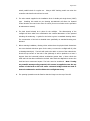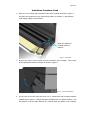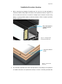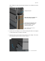
1
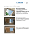
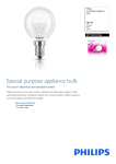
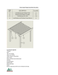
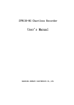
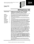
GV Standard Pyramid
Installation Instruction Manual
“Technical experts in the design, manufacture and supply of precision engineered,
architectural rooflights for residential and commercial buildings.”
Page 2 of 8
Pyramid Installation Instruction Manual
VV-INST – v2.1 – 30.01.15
Contents
Section Description
Page
Contents
2
Installation
2
Installation Procedure: Fixed
3
Installation Procedure: Opening
6
Pyramid Installation Instructions
Points to note prior to commencing installation:
1. The Pyramid should arrive on site in undamaged packaging, which includes sterling
board side protection, polyfoam glass protection and low-tack tape base protection.
Please inspect for damage to packaging and/or rooflight and advise Glazing Vision
upon receipt.
2. Enclosed within the box containing this manual is a roll of butyl tape, the required
number of fixing woodscrews and a number of horseshoe packers. The installation
kit supplied with electrical units contains a transformer, two switches and any
additional optional items selected at time of order.
3. For electrically operated Pyramids there are two standard cables emerging from the
motor housing, this includes two and six core cables both of which have red
identification labels (labels should not be removed until final installation) refer to
Glazing Vision standard drawing 404-ASS-426 for details of wiring requirements.
4.
The switch used to control the operation of the Pyramid is a single pole double throw
(SPDT) centre sprung type. This switch will allow you to operate and stop at any
position between the fully open and closed positions. This switch also contains a tricolour LED to display rooflight status to the user.
The correct control switch is
supplied in the installation kit and must be installed to avoid invalidating the
warranty. This switch can be installed in a maintenance area if required and another
GLAZING VISION Ltd, Saw Mills Road, Diss, Norfolk, IP22 4RG
Telephone: 0333 8000 881 Fax: 0333 8000 882
Registered in England and Wales Reg. No. 2987024
Page 3 of 8
switch parallel wired for regular use. Using a SPDT latching switch can seize the
controller and therefore should not be used.
5. The other switch supplied in the installation kit is of double pole single throw (DPST)
type.
Installing this switch as per drawing 404-ASS-426 will allow the Pyramid
control board to be reset in the event of a fault (for more on faults see the operation
& maintenance manual).
6. The kerb should already be in place for the rooflight.
The dimensioning of the
rooflight will have taken into consideration the external dimensions of the upstand
including all weathering. A guide for the kerbs is given in standard drawing S0001.
The construction of the kerb is detailed more specifically on standard drawing 404ASS-402.
7. Before starting installation, Glazing Vision advises that the physical kerb dimensions
are cross-checked with those given for the order, to ensure the rooflight will fit (refer
to drawings S0009/10). The kerb will need to be within ± 10mm of the ordered size.
Check the top surface of the kerb is flat (although it will be pitched to at least 3
degrees from the horizontal) without undulations greater than +/-2mm. Check the
cable exit hole has been included in the kerb. Also check the diagonals to ensure the
kerb has been constructed square. The kerb must be weathered. Note: if using
any metallic waterproofing material, this cannot be applied across the top
surface of the kerb as this will cause a thermal bridge which can lead to
internal condensation and invalidate the rooflight warranty.
8. The opening Pyramids must be fitted so that the hinge is at the top of the fall.
Page 4 of 8
Installation Procedure: Fixed
1. Place two runs of butyl tape around the base of the Pyramid as shown in Figure 1,
and place the Pyramid onto your kerb ensuring that it is centred, i.e. drip flashing
overhanging equally round all sides.
Butyl tape applied to
rooflight extrusion
features
Figure 1 – Butyl tape
1. Remove the clip on covers around the lower perimeter of the rooflight. This is done
by first pulling the bottom to release as shown in Figure 2.
Figure 2 – Clip release direction
2. Fix the vent to the kerb using the No10 x 2½” woodscrews and horseshoe packers
supplied as per Figure 3. Fixings should be predrilled 3mm to a depth of 50mm. Use
the packers to fill the space between the external kerb and inside of the rooflight.
Page 5 of 8
Care should be taken when tightening the fixings to ensure the frame does not
distort.
Figure 3 – Packing and fixing
3. After applying all fixings clip on the covers around the base perimeter.
4. For connecting the Pyramid downlighter, please refer to Glazing Vision’s standard
drawing 404-ASS-426.
Page 6 of 8
Installation Procedure: Opening
1. Before removing the packaging if possible turn the vent on to its side and apply 2
continuous beads of butyl tape to the base of the Pyramid as shown in Figure 4. If
the vent cannot be turned on to its side the rooflight can be sealed to the kerb using
silicone. For this operation apply 2 continuous beads of silicone roughly in positions
shown in Figure 5.
Butyl tape applied to
rooflight extrusion
features
Figure 4 – Rooflight section
showing butyl positioning.
Continuous silicone
beads
Figure 5 – Silicone bead
positioning.
2. For electrically operated vents ensure that provision for the cabling in the upstand is
of suitable dimensions and positioned correctly as shown on drawing 404-ASS-426.
Page 7 of 8
Figure 6 depicts the cables exiting through the bottom of the rooflight into the kerb
structure:
Rooflight framework
Cable exiting bottom of rooflight to be
fed into kerb during installation.
Kerb structure with cable entry hole
refer to drawing 404-ASS-414 for
dimensioning details. Kerb not
supplied by Glazing Vision
Figure 6- Position of power and control
cables in motor housing
3. Carefully lower the rooflight onto the kerb top ensuring that cables are not trapped
i.e. that the base frame is not sitting on the cables.
4. Remove the clip on covers around the lower perimeter of the rooflight. This is done
by first pulling the bottom to release as shown in Figure 7.
Figure 7 – Clip release direction
Page 8 of 8
5. Fix the vent to the kerb using the No10 x 2½” woodscrews and horseshoe packers
supplied as per Figure 8. Fixings should be predrilled 3mm to a depth of 50mm. Use
the packers to fill the space between the external kerb and inside of the rooflight.
Care should be taken when tightening the fixings to ensure the frame does not
distort.
Figure 8 – Packing and fixing
6. After applying all fixings clip on the covers around the base perimeter.
7. To complete the installation the flying connections from the vent must be terminated
as per drawing 404-ASS-426. It is recommended the transformer is placed within
10m of the Pyramid unit. Any extension to the switch lead should be a 0.5mm2 cable
and any power lead should be a 0.75mm 2 cable up to a maximum of 10m to avoid
significant voltage drop and . Please note NO power must be placed onto the sixcore switch cable.
8. To commission the Pyramid, first check there are no obstructions preventing the lid
from moving freely e.g. scaffolding or loads placed on the lid. Check also that the
mechanism has not been disengaged from the lid and the override pins have not
been removed.
There is no reason to disengage the mechanisms to install the
Pyramid but failure to check this could result in mechanical damage. Switch on the
mains to the 24V supply. If the mechanisms cannot be seen from the switch position
ask for assistance – when operating the Pyramid for the first time it is important to
check that both mechanisms are working in tandem. When you are ready to run the
Pyramid press and hold the operating switch in the open direction.
If the
mechanisms do not function as expected within a few seconds release the switch and
contact Glazing Vision for assistance.