1
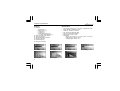
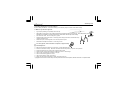
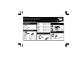
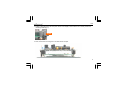
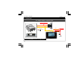
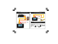
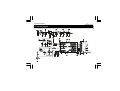
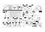
Total solder points: 123
Difficulty level: beginner 1
2
3
4
5
advanced
AUDIO ANALYZER
K8098
ra
audio gea
Give your
.
look
high-tech
ILLUSTRATED ASSEMBLY MANUAL
H8098IP-1
Features & Specifications
Features
Specifications
measure:
peak power (fig.1)
RMS power (fig.2)
mean dB (fig.3)
peak dB (fig.4)
linear audio spectrum (fig.5)
1/3 octave audio spectrum (fig.6)
auto or manual range selection
peak-hold function
speaker impedance selection
language selection
white backlit LCD
easy panel mounting
2
power measurement into 2, 4 or 8 ohms + bridged amp option
range: 300mW to 1200W @ 2 ohms
sensitivity: -34dBu (15.5 mVrms)
max. input level: 50Vrms @ 220k
frequency range: 20Hz to 20kHz
power supply: 12VDC / 75mA
dimensions:
display: 128 x 64mm / 5 x 2.5" (46 x 24mm / 1.8 x 0.95")
front panel: 98 x 51mm / 3.8 x 2"
mounting depth: 35mm / 1.37"
fig.1
fig.2
fig.3
fig.5
fig.6
ex. reversed
fig.4
Assembly hints
1. Assembly (Skipping this can lead to troubles ! )
Ok, so we have your attention. These hints will help you to make this project successful. Read them carefully.
1.1 Make sure you have the right tools:
•
A good quality soldering iron (25-40W) with a small tip.
•
Wipe it often on a wet sponge or cloth, to keep it clean; then apply solder to the tip, to give it a wet look. This is called ‘thinning’ and will
protect the tip, and enables you to make good connections. When solder rolls off the tip, it needs cleaning.
•
Thin raisin-core solder. Do not use any flux or grease.
•
A diagonal cutter to trim excess wires. To avoid injury when cutting excess leads, hold the lead so they
cannot fly towards the eyes.
•
Needle nose pliers, for bending leads, or to hold components in place.
•
Small blade and Phillips screwdrivers. A basic range is fine.
0.0
00
For some projects, a basic multi-meter is required, or might be handy
1.2 Assembly Hints :
⇒
⇒
⇒
⇒
⇒
⇒
⇒
⇒
Make sure the skill level matches your experience, to avoid disappointments.
Follow the instructions carefully. Read and understand the entire step before you perform each operation.
Perform the assembly in the correct order as stated in this manual
Position all parts on the PCB (Printed Circuit Board) as shown on the drawings.
Values on the circuit diagram are subject to changes.
Values in this assembly guide are correct*
Use the check-boxes to mark your progress.
Please read the included information on safety and customer service
* Typographical inaccuracies excluded. Always look for possible last minute manual updates, indicated as ‘NOTE’ on a separate leaflet.
3
Assembly hints
1.3 Soldering Hints :
1- Mount the component against the PCB surface and carefully solder the leads
2- Make sure the solder joints are cone-shaped and shiny
3- Trim excess leads as close as possible to the solder joint
REMOVE THEM FROM THE TAPE ONE AT A TIME !
DO NOT BLINDLY FOLLOW THE ORDER OF THE
COMPONENTS ONTO THE TAPE. ALWAYS CHECK
THEIR VALUE ON THE PARTS LIST!
4
Construction
The audio analyzer consist of three parts: the basic module, the display module and the front panel.
If required you can mount this kit into a housing, panel, ...
In this case use the display gap as a marker reference.
First we assemble the basic module.
1. Jumper wire
J1 ... J6
2. Horizontal resistors
R...
R8
R9
R10
R11, R12
R13
R14
R15
R16
R17
R18
:
:
:
:
:
:
:
:
:
:
750 (7 - 5 - 1 - B)
180K (1 - 8 - 4 - B)
2K2 (2 - 2 - 2 - B)
6K8 (6 - 8 - 2 - B)
680 (6 - 8 - 1 - B)
3K3 (3 - 3 - 2 - B)
750 (7 - 5 - 1 - B)
5K6 (5 - 6 - 2 - B)
220 (2 - 2 - 1 - B)
22K (2 - 2 - 3 - B)
IC1 : 8p
IC2 : 28p
5. HF-Choke
3. Diode. Watch the polarity!
D1 : 1N4007
R1
R2, R3
R4
R5, R6
R7
4. IC socket. Watch the
position of the notch!
:
:
:
:
:
470 (4 - 7 - 1 - B)
1K (1 - 0 - 2 - B)
220K (2 - 2 - 4 - B)
33K (3 - 3 - 3 - B)
22K (2 - 2 - 3 - B)
CATHODE
D...
L2
L...
L1 : 4700µH (4 - 7 - 2 )
5
construction
6. Voltage regulator
VR1: LM317
9. Electrolytic Capacitor.
Watch the polarity !
8. Pin header
9x
1
C4, C5 : 10µF
C6, C7 : 220µF
C8, C14 : 4,7µF
9x
C...
2
10. Board-to-wire connector
(a)
7. Capacitors.
SK1
(b)
11. Push button
C1…C3
C9
C10
C11
:
:
:
:
100nF
4.7nF
470pF
47pF
(104)
(472)
(471)
(47)
C12,C13 & X1 are not
mounted !
6
SW1
3
Solderside
Mount the button
on the solderside !
Construction
12. IC. Watch the
position of the notch!
13. Pin header
IC1 : MCP6002-E/P
Component side
IC2 : VKVPA20 programmed
DSPIC33FJ32I/SP
Display side
Mount the female connector on the component side, solder
on the display side!
7
LCD
14. Assembly
1.Roughen the 4 bolts with a knife, a file or some abrasive paper so it will be easier to solder them to the
front panel.
2. Assemble the unit but do not yet tighten the bolts (fig.1).
Fig.1
3. Position the unit onto the rear of the front panel with the display is centred in the cut-away.
Temporarily fix the unit to the rear using non-permanent tape (fig. 2).
Fig.2
8
LCD
4. Solder 2 diagonal bolts to the front panel. Check if the display is still centred in the cut-away. Solder the
remaining 2 bolts (fig. 3).
Solder
Fig.3
5. Now, fix the whole unit using the 4 nuts and remove the tape.
9
Connection examples
15. CONNECTION
Ex. "bridged" amplifier or high power radio
DO NOT CONNECT TO K8098 !
Speaker OUT
'Bridged' *
Amplifier
+
Orange
+ Battery
GND / chassis
Do not connect!
Red
Yellow
Brown
Signal IN
OR
High-Power
car radio
GND
+12V
Battery
*Activate BRIDGED function in setup-menu !
10
Connection examples
Ex. connected to speaker output
Ex. connected to LINE OUT
Yellow
Amplifier, ex. K8081
Orange
Speaker out
+
Red
Brown
-
12VDC
TO
LINE OUT
Yellow
Signal IN
Orange
Signal
SIFGNAL IN
Red
Brown
+
12VDC
-
HINT for stereo connection
10K
L+
From
Amplifier or
Line OUT R+
SIGNAL TO
K8098
10K
11
Use
16. USE
Short press on the 'mode' button: selecting a meter-display.
Long press on the 'mode' button: opening the set-up menu.
Set-up menu
Access to the Set-up menu by a "long" push on the 'mode' button.
Short press: changing settings
long press: next function
Keep pressed: save changes and exit
Speed: refreshing the screen (Fast - Mid - Slow)
Impedance: "2", "4" or "8" ohms for speaker output power calculation, in case the unit is connected to speaker output.
Power: "AUTO" range or a maximum value that depends on the chosen impedance.
For impedance = 2: Possible choices are "1200 mW", "12W", "120W" or "1200W"
For impedance = 4: Possible choices are "600 mW", "6W", "60W" or "600W"
For impedance = 8: Possible choices are "300 mW", "3W", "30W" or "300W"
Sticky Bar: "Yes" or "No"
When selected, small residual sticky bars appear also on the third octave spectrum screen.
Spectrum dB: "dBu" or "110 dB". (110 dB stands for the "Power dB" display which can range from 80dB to
110dB max, depending on the selected Power range).
Advanced settings: see pag. 10
12
Advanced settings
Advanced settings
First open the set-up menu with a long press on the 'mode' button and
choose the mode "advanced settings".
Short press: changing settings
long press: next function
Keep pressed: save changes and exit
Language: UK / NL / FR / DE / ES
Contrast : choose a contrast between 1 - 20
Reverse video: normal or reverse display
True mean: Yes or no.
If 'no' is selected then the display gives the integrated "peak values".
If a pure sine wave is used both values will be the same.
Bridge amplifier: Turn on in case of in car use with high power radio or amplifier.
Demo: showing the different screen layouts, you can choose (slow - fast - off)
13
Schematic diagram
17. Schematic diagram
R15
750
14
PCB
18. PCB
+
15
Modifications and typographical errors reserved
© Velleman nv.
H8098IP'1 - 2010_rev1
VELLEMAN NV
Legen Heirweg 33, 9890 Gavere
Belgium - Europe
5 410329 421724