1
Shiokoji Horikawa, Shimogyo-ku,
Kyoto, 600-8530 Japan
Tel: (81)75-344-7080/Fax: (81)75-344-7189
Regional Headquarters
OMRON EUROPE B.V.
Wegalaan 67-69, NL-2132 JD Hoofddorp
The Netherlands
Tel: (31)2356-81-300/Fax: (31)2356-81-388
OMRON ASIA PACIFIC PTE. LTD.
83 Clemenceau Avenue,
#11-01, UE Square,
239920 Singapore
Tel: (65)6835-3011/Fax: (65)6835-2711
OMRON CHINA CO., LTD.
BEIJING OFFICE
Room 1028, Office Building,
Beijing Capital Times Square,
No. 88 West Chang'an Road,
Beijing, 100031 China
Tel: (86)10-8391-3005/Fax: (86)10-8391-3688
Cat. No. H130-E1-01
Note: Specifications subject to change without notice.
Overview
User's Manual
H130-E1-01
Authorized Distributor:
User's Manual
OMRON ELECTRONICS LLC
1 East Commerce Drive, Schaumburg, IL 60173
U.S.A.
Tel: (1)847-843-7900/Fax: (1)847-843-8568
Communications Functions
Printed in Japan
0604-1M (0604) (?)
Com Data
Measuring and Control Division
Digital Temperature Controller
Cat. No. H130-E1-01
Appendix
Industrial Automation Company
SYSWAY
E5CN Digital Temperature Controller Communications Functions
OMRON Corporation
Preface
The E5CN supports CompoWay/F and SYSWAY serial communications specifications.
This User's Manual describes the communications functions of the E5CN. Before using your
E5CN, thoroughly read and understand this manual in order to ensure correct use. Also, store
this manual in a safe place so that it can be retrieved whenever necessary.
E OMRON, 2004
All rights reserved. No part of this publication may be reproduced, stored in a retrieval system or transmitted, in
any form, or by any means, mechanical, electronic, photocopying, recording, or otherwise, without the prior written
permission of OMRON.
No patent liability is assumed with respect to the use of the information contained herein. Moreover, because
OMRON is constantly striving to improve its high-quality products, the information contained in this manual is
subject to change without notice. Every precaution has been taken in the preparation of this manual. Nevertheless,
OMRON assumes no responsibility for errors or omissions. Neither is any liability assumed for damages resulting
from the use of the information contained in this publication.
I
Read and Understand this Manual
Please read and understand this manual before using the product. Please consult your OMRON
representative if you have any questions or comments.
Warranty and Limitations of Liability
WARRANTY
OMRON's exclusive warranty is that the products are free from defects in materials and workmanship
for a period of one year (or other period if specified) from date of sale by OMRON.
OMRON MAKES NO WARRANTY OR REPRESENTATION, EXPRESS OR IMPLIED, REGARDING
NON-INFRINGEMENT, MERCHANTABILITY, OR FITNESS FOR PARTICULAR PURPOSE OF THE
PRODUCTS. ANY BUYER OR USER ACKNOWLEDGES THAT THE BUYER OR USER ALONE HAS
DETERMINED THAT THE PRODUCTS WILL SUITABLY MEET THE REQUIREMENTS OF THEIR
INTENDED USE. OMRON DISCLAIMS ALL OTHER WARRANTIES, EXPRESS OR IMPLIED.
LIMITATIONS OF LIABILITY
OMRON SHALL NOT BE RESPONSIBLE FOR SPECIAL, INDIRECT, OR CONSEQUENTIAL
DAMAGES, LOSS OF PROFITS OR COMMERCIAL LOSS IN ANY WAY CONNECTED WITH THE
PRODUCTS, WHETHER SUCH CLAIM IS BASED ON CONTRACT, WARRANTY, NEGLIGENCE, OR
STRICT LIABILITY.
In no event shall the responsibility of OMRON for any act exceed the individual price of the product on
which liability is asserted.
IN NO EVENT SHALL OMRON BE RESPONSIBLE FOR WARRANTY, REPAIR, OR OTHER CLAIMS
REGARDING THE PRODUCTS UNLESS OMRON'S ANALYSIS CONFIRMS THAT THE PRODUCTS
WERE PROPERLY HANDLED, STORED, INSTALLED, AND MAINTAINED AND NOT SUBJECT TO
CONTAMINATION, ABUSE, MISUSE, OR INAPPROPRIATE MODIFICATION OR REPAIR.
Application Considerations
SUITABILITY FOR USE
OMRON shall not be responsible for conformity with any standards, codes, or regulations that apply to
the combination of products in the customer's application or use of the products.
At the customer's request, OMRON will provide applicable third party certification documents identifying
ratings and limitations of use that apply to the products. This information by itself is not sufficient for a
complete determination of the suitability of the products in combination with the end product, machine,
system, or other application or use.
The following are some examples of applications for which particular attention must be given. This is not
intended to be an exhaustive list of all possible uses of the products, nor is it intended to imply that the
uses listed may be suitable for the products:
• Outdoor use, uses involving potential chemical contamination or electrical interference, or conditions
or uses not described in this manual.
• Nuclear energy control systems, combustion systems, railroad systems, aviation systems, medical
equipment, amusement machines, vehicles, safety equipment, and installations subject to separate
industry or government regulations.
• Systems, machines, and equipment that could present a risk to life or property.
Please know and observe all prohibitions of use applicable to the products.
NEVER USE THE PRODUCTS FOR AN APPLICATION INVOLVING SERIOUS RISK TO LIFE OR
PROPERTY WITHOUT ENSURING THAT THE SYSTEM AS A WHOLE HAS BEEN DESIGNED TO
ADDRESS THE RISKS, AND THAT THE OMRON PRODUCTS ARE PROPERLY RATED AND
INSTALLED FOR THE INTENDED USE WITHIN THE OVERALL EQUIPMENT OR SYSTEM.
PROGRAMMABLE PRODUCTS
OMRON shall not be responsible for the user's programming of a programmable product, or any
consequence thereof.
II
Disclaimers
CHANGE IN SPECIFICATIONS
Product specifications and accessories may be changed at any time based on improvements and other
reasons.
It is our practice to change model numbers when published ratings or features are changed, or when
significant construction changes are made. However, some specifications of the products may be
changed without any notice. When in doubt, special model numbers may be assigned to fix or establish
key specifications for your application on your request. Please consult with your OMRON representative
at any time to confirm actual specifications of purchased products.
DIMENSIONS AND WEIGHTS
Dimensions and weights are nominal and are not to be used for manufacturing purposes, even when
tolerances are shown.
PERFORMANCE DATA
Performance data given in this manual is provided as a guide for the user in determining suitability and
does not constitute a warranty. It may represent the result of OMRON's test conditions, and the users
must correlate it to actual application requirements. Actual performance is subject to the OMRON
Warranty and Limitations of Liability.
ERRORS AND OMISSIONS
The information in this document has been carefully checked and is believed to be accurate; however,
no responsibility is assumed for clerical, typographical, or proofreading errors, or omissions.
III
Safety Precautions
■ Definition of Precautionary Information
The following notation is used in this manual to provide precautions required to
ensure safe usage of the product.
The safety precautions that are provided are extremely important to safety. Always
read and heed the information provided in all safety precautions.
The following notation is used.
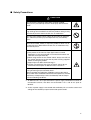
CAUTION
Indicates a potentially hazardous situation which, if not
avoided, is likely to result in minor or moderate injury or
in property damage.
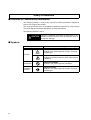
■ Symbols
Symbol
Meaning
General Caution
Indicates non-specific general cautions, warnings,
and dangers.
Caution
Electrical Shock Caution
Indicates possibility of electric shock under specific
conditions.
IV
Prohibition
General Prohibition
Indicates non-specific general prohibitions.
Mandatory
Caution
General Caution
Indicates non-specific general cautions, warnings,
and dangers.
■ Safety Precautions
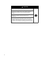
CAUTION
Do not touch the terminals while power is being supplied.
Doing so may occasionally result in minor injury due to electric
shock.
Do not allow pieces of metal, wire clippings, or fine metallic shavings or filings from installation to enter the product. Doing so may
occasionally result in electric shock, fire, or malfunction.
Do not use the product where subject to flammable or explosive
gas. Otherwise, minor injury from explosion may occasionally
occur.
Never disassemble, modify, or repair the product or touch any of
the internal parts. Minor electric shock, fire, or malfunction may
occasionally occur.
CAUTION - Risk of Fire and Electric Shock
a) This product is UL listed as Open Type Process Control
Equipment. It must be mounted in an enclosure that does not
allow fire to escape externally.
b) When using more than one shutoff switch, always turn OFF all
the shutoff switches to ensure that no power is being supplied
before servicing the product.
c) Signal inputs are SELV, limited energy.*1
d) Caution: To reduce the risk of fire or electric shock, do not
interconnect the outputs of different Class 2 circuits.*2
If the output relays are used past their life expectancy, contact
fusing or burning may occasionally occur.
Always consider the application conditions and use the output
relays within their rated load and electrical life expectancy. The life
expectancy of output relays varies considerably with the output
load and switching conditions.
*1 An SELV circuit is one separated from the power supply with double insulation or
reinforced insulation, that does not exceed 30 V r.m.s. and 42.4 V peak or
60 VDC.
*2 A class 2 power supply is one tested and certified by UL as have the current and
voltage of the secondary output restricted to specific levels.
V
CAUTION
Tighten the terminal screws to between 0.74 and 0.9 N.m. Loose
screws may occasionally result in fire.
Set the parameters of the product so that they are suitable for the
system being controlled. If they are not suitable, unexpected
operation may occasionally result in property damage or
accidents.
WARNING: To reduce the risk of electric shock or fire, install the
product in a controlled environment relatively free of
contaminants.
A malfunction in the Temperature Controller may occasionally
make control operations impossible or prevent alarm outputs,
resulting in property damage. To maintain safety in the event of
malfunction of the Temperature Controller, take appropriate safety
measures, such as installing a monitoring device on a separate
line.
VI
Precautions for Safe Use
1)
2)
3)
4)
5)
6)
7)
8)
9)
10)
11)
12)
13)
14)
Do not use this product in the following places:
• Places directly subject to heat radiated from heating equipment.
• Places subject to splashing liquid or oil atmosphere.
• Places subject to direct sunlight.
• Places subject to dust or corrosive gas (in particular, sulfide gas and ammonia gas).
• Places subject to intense temperature change.
• Places subject to icing and condensation.
• Places subject to vibration and large shocks.
Use and store the Digi7tal Temperature Controller within the rated ambient temperature and humidity.
Gang-mounting two or more temperature controllers, or mounting temperature controllers above each
other may cause heat to build up inside the temperature controllers, which will shorten their service
life. In such a case, use forced cooling by fans or other means of air ventilation to cool down the
Digital Temperature Controllers.
To allow heat to escape, do not block the area around the product. Do not block the ventilation holes
on the product.
Be sure to wire properly with correct polarity of terminals.
Use specified size (M3.5, width 7.2 mm or less) crimped terminals for wiring. Use wires with a gage of
AWG24 to AWG14 (equal to cross-sectional areas of 0.205 to 2.081 mm2). (The stripping length is 5
to 6 mm.)
Do not wire the terminals which are not used.
To avoid inductive noise, keep the wiring for the Digital Temperature Controller's terminal block away
from power cables carry high voltages or large currents. Also, do not wire power lines together with or
parallel to Digital Temperature Controller wiring. Using shielded cables and using separate conduits or
ducts is recommended.
Attach a surge suppressor or noise filter to peripheral devices that generate noise (in particular,
motors, transformers, solenoids, magnetic coils or other equipment that have an inductance
component).
When a noise filter is used at the power supply, first check the voltage or current, and attach the noise
filter as close as possible to the temperature controller.
Allow as much space as possible between the Digital Temperature Controller and devices that
generate powerful high frequencies (high-frequency welders, high-frequency sewing machines, etc.)
or surge.
Use this product within the rated load and power supply.
Make sure that the rated voltage is attained within two seconds of turning the power ON.
Make sure the controller has 30 minutes or more for warm up.
When using self-tuning, turn ON power for the load (e.g., heater) at the same time as or before
supplying power to the Digital Temperature Controller. If power is turned ON for the Digital Temperature Controller before turning ON power for the load, self-tuning will not be performed properly and
optimum control will not be achieved.
A switch or circuit breaker should be provided close to this unit. The switch or circuit breaker should
be within easy reach of the operator, and must be marked as a disconnecting means for this unit.
Always turn OFF the power supply before pulling out the interior of the product, and never touch nor
apply shock to the terminals or electronic components. When inserting the interior of the product, do
not allow the electronic components to touch the case.
Do not use paint thinner or similar chemical to clean with. Use standard grade alcohol.
VII
15) Design system (control panel, etc) considering the 2 second of delay that the controller’s output to be
set after power ON.
16) The output may turn OFF when shifting to certain levels. Take this into consideration when performing
control.
VIII
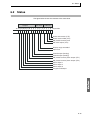
Conventions Used in This Manual
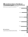
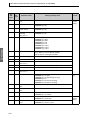
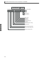
■ How This Manual is Organized
Overview
Descriptions in this manual are separated by the communications method.
Read the sections that are application to the system being used.
Overview
Com Data
CompoWay/F
SYSWAY
Communications Data
CompoWay/F•SYSWAY
SYSWAY
Appendix
Modbus
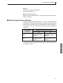
■ Related Manuals
This manual describes the communications functions of the E5CN.
For details on the functions of the E5CN, refer to the User's Manual.
Appendix
IX
X
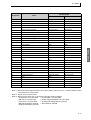
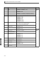
Table of Contents
Preface - - - - - - - - - - - - - - - - - - - - - - - - - - - - - - I
Read and Understand this Manual - - - - - - - - - - II
Warranty and Limitations of Liability - - - - - - - - - II
Application Considerations - - - - - - - - - - - - - - - - II
Disclaimers - - - - - - - - - - - - - - - - - - - - - - - - - - - III
Safety Precautions - - - - - - - - - - - - - - - - - - - - -IV
Precautions for Safe Use - - - - - - - - - - - - - - - - VII
Conventions Used in This Manual - - - - - - - - - - -IX
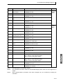
SECTION 1
Communications Methods
1.1
Overview of Communications Methods....................................................... 1-2
Introduction .......................................................................................... 1-2
Communications Specifications ........................................................... 1-3
Transmission Procedure ...................................................................... 1-3
Interface ............................................................................................... 1-4
Wiring................................................................................................... 1-4
Communications Parameters............................................................... 1-5
SECTION 2
CompoWay/F Communications Procedures
2.1
Data Format ................................................................................................ 2-2
Command Frame ................................................................................. 2-2
Response Frame ................................................................................. 2-3
Communications Data.......................................................................... 2-4
End Code Example .............................................................................. 2-4
2.2
Structure of Command Text ........................................................................ 2-6
PDU Structure...................................................................................... 2-6
Area Definitions.................................................................................... 2-6
Type Code (Variable Type).................................................................. 2-6
Addresses ............................................................................................ 2-7
Number of Elements ............................................................................ 2-7
List of Services..................................................................................... 2-7
2.3
Detailed Description of the Services ........................................................... 2-9
Read Variable Area.............................................................................. 2-9
Write Variable Area............................................................................ 2-10
Read Controller Attributes.................................................................. 2-12
Read Controller Status....................................................................... 2-13
Echoback Test ................................................................................... 2-14
Operation Command.......................................................................... 2-15
2.4
Response Code List.................................................................................. 2-20
SECTION 3
Communications Data for CompoWay/F and SYSWAY
3.1
Variable Area (Setting Range) List.............................................................. 3-2
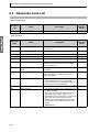
3.2
Status ........................................................................................................ 3-15
XI
SECTION 4
SYSWAY (E5@J and E5@X Format) Communications Procedures
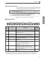
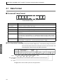
4.1
Data Format ................................................................................................ 4-2
Command Frame Format..................................................................... 4-2
Response Frame ................................................................................. 4-3
Communications Data.......................................................................... 4-3
SYSWAY Command Lists.................................................................... 4-4
4.2
Command Descriptions............................................................................... 4-5
Read Process Value ............................................................................ 4-5
Write Set Values .................................................................................. 4-6
Read Set Values and MV Monitor........................................................ 4-7
Select Communications Writing ........................................................... 4-9
SECTION 5
Modbus Communications Procedure
5.1
Data Format ................................................................................................ 5-2
Command Frame ................................................................................. 5-2
Response Frame ................................................................................. 5-4
Error Codes.......................................................................................... 5-5
5.2
Function List................................................................................................ 5-6
5.3
Variable Area............................................................................................... 5-7
5.4
Detailed Description of the Services ........................................................... 5-9
Read Variable Area.............................................................................. 5-9
Write Variable Area ............................................................................ 5-11
Operation Commands ........................................................................ 5-14
Echoback Test ................................................................................... 5-19
SECTION 6
Communications Data for Modbus
6.1
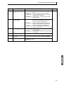
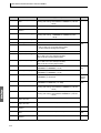
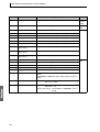
Variable Area (Setting Range) List.............................................................. 6-2
6.2
Status ........................................................................................................ 6-15
Appendix
ASCII List ..............................................................................................................A-2
XII
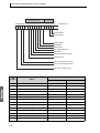
SECTION 1
Communications Methods
This section briefly describes the supported communications methods and
how to wire equipment. Refer to this section when setting up equipment.
1.1
Overview of Communications Methods ........................ 1-2
Introduction.............................................................. 1-2
Communications Specifications............................... 1-3
Transmission Procedure.......................................... 1-3
Interface................................................................... 1-4
Wiring ...................................................................... 1-4
Communications Parameters .................................. 1-5
Communications Parameter Setup .......... 1-5
Communications Parameters ................... 1-6
1-1
SECTION 1 Communications Methods
Overview
1.1 Overview of Communications Methods
■ Introduction
The program for the communications functions are created on the host
computer, and the E5CN’s parameters are monitored or set from the host
computer. Therefore, the description provided here is from the viewpoint of the
host computer.
CompoWay/F is OMRON’s standard communications format for general serial
communications. This format uses a standard frame format as well as the
well-established FINS* commands used for OMRON’s PLCs. Therefore, it can
simplify communications between components and the host computer.
*FINS (Factory Interface Network service)
The FINS protocol provides message communications between controllers in
OMRON FA networks.
Modbus is a standard communications control method that conforms to the
Modicon Company’s RTU-mode Modbus Protocol (PI-MBUS-300 Revision J).
Supports functions equivalent to the CompoWay/F Read Variable Area, Write
Variable Area, Operation Command, and Echoback Test functions.
The E5CN supports the following communications functions.
• Reading/writing of parameters
• Operation instructions
• Selection of setup levels
Communications are subject to the following condition:
• Parameters can be written only when the “communications writing” parameter
is set to ON (enabled).
1-2
1.1 Overview of Communications Methods
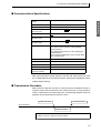
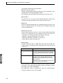
Transmission line connection
RS-485: Multidrop
Communications method
RS-485 (2-wire, half-duplex)
Synchronization method
Start-stop synchronization
Communications baud
rate (See note.)
1,200, 2,400, 4,800, 9,600, 19,200 or 38,400 bps
Communications code
ASCII
Communications data
bits (See note.)
7 or 8 bits
Communications stop
bits (See note.)
1 or 2 bits
Error detection
Vertical parity (none, even, or odd)
FCS (Frame Check Sequence) with SYSWAY
communications
BCC (Block Check Character) with CompoWay/F
communications
CRC-16 (Cyclic Redundancy Check 16) with Modbus communications
Flow control
None
Interface
RS-485
Retry function
None
Communications buffer
40 bytes
Communications
response wait time
0 to 99 ms, default time: 20 ms
Overview
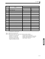
■ Communications Specifications
Note: Communications speed, data bits, stop bits and vertical parity can each
be set independently in the communications setting level. Highlighted values
indicate default settings.
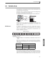
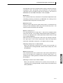
■ Transmission Procedure
When the host computer transmits a command frame, the E5CN transmits a
response frame that corresponds to the command frame. A single response
frame is returned for each command frame. The following diagram shows the
operation of the command and response frames.
Command frame
Command frame
Host computer
E5CN
Response frame
Allow a wait time of at least 2 ms before the next command is sent after the host
computer receives a response from the E5CN.
1-3
SECTION 1 Communications Methods
■ Interface
Communications with the host computer are carried out through a standard
RS-485 interface. Use a K3SC Interface Converter for RS-485 interface
Overview
conversion.
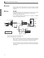
■ Wiring
RS-485
• The RS-485 connection can be either one-to-one or one-to-N. Up to 32 units
including the host computer can be connected in a one-to-N system.
• The total cable length is 500 m max.
• Use a shielded twisted-pair cable with wires of a thickness of AWG24
(0.205 mm2) to AWG14 (2.081 mm2).
Communications transceiver
Host computer side
RS-485
E5CN side
RS-485
Abbreviation
Pin
12
A (−)
11
B (+)
Abbreviation
FG
−
+
SG
6.8 V
Shield
Terminator
120
(1/2 W
A < B: "1" Mark
A > B: "0" Space
Shield
E5CN side
End node
RS-485
Abbreviation
Pin
12
A (−)
11
B (+)
Use a 120 Ω (1/2 W)
terminator.
Specify both ends of the transmission path including the host
computer as the end node (that is, connect terminators to both
ends). Use a terminating resistance of at least 54 Ω.
Match the communications specifications of the E5CN and the host computer.
When using a 1: N connection, set the same communications specifications in
all of the Units. (Of course, each Unit must have a unique unit number.)
This section explains how to set the E5CN’s communications specifications.
For details on the host computer, refer to the User’s Manual provided with the
host computer.
1-4
1.1 Overview of Communications Methods
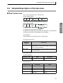
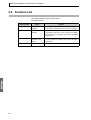
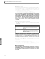
■ Communications Parameters
The E5CN’s communications specifications are set in the communications
setting level. These parameters are set on the E5CN’s front panel. The
following table shows the communications parameters and their setting
Item
Code
Settings
Overview
ranges.
Set Values
Communications protocol
psel
CompoWay/F (SYSWAY)/Modbus
cwf/mod
Communications unit number
u-no
0 to 99
0,1 to 99
Communications baud rate
bps
1.2/2.4/4.8/9.6/19.2/38.4 (kbit/s)
1.2/2.4/4.8/9.6 /19.2/38.4 (kbit/s)
Communications data length
len
7/8 (bit)
7 /8 (bit)
Communications stop bits
sbit
1/2
1/ 2
Communications parity
prty
None, Even, Odd
none/ eVen /odd
Send data wait time
sdwt
0 to 99
0 to 99 ms, default time: 20 ms
Highlighted values indicate default settings.
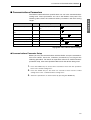
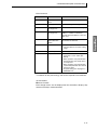
● Communications Parameter Setup
Before you carry out communications with the E5CN, set up the communications unit number, baud rate, and other parameters by carrying out the
following procedure. For details on operations other than communications
parameter setup, refer to the Operation Manuals for the devices being used.
1.
Press the LEVEL Key for at least three seconds to move from the “operation
level” to the “initial setting level.”
2.
Press the LEVEL Key for less than one second to move from the “initial
setting level” to the “communications setting level.”
3.
Select the parameters as shown below by pressing the MODE Key.
1-5
SECTION 1 Communications Methods
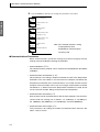
4.
Use the DOWN or UP Keys to change the parameter set values.
c
psel
Protocol selection
Overview
cwf
c
u-no
Communications unit
number
1
c
bps
Communications
baud rate
9.6
c
len
Communications data
length (See note.)
7
c
56it
2
c
prty
Communications stop
bits (See note.)
Communications
parity
eVen
c
sdwt
Note: The “Protocol selection” setting
Send data wait time
20
is displayed only when
CompoWay/F communications
are being used.
● Communications Parameters
When communications parameter settings have been changed, the new
settings must be enabled by resetting the Controller.
• Protocol Selection (psel)
The communications protocol can be selected. Set CompoWay/F (SYSWAY)
or Modbus.
• Communications Unit Number (u-no)
This parameter is for setting a unique unit number for each of the Temperature
Controllers. This unit number is set so that the host computer can identify the
Temperature Controller when communications are carried out with the host
computer. The unit number can be set to an integer value between 0 and 99.
The default is “1.” When two or more Temperature Controllers are used, do not
set the same unit number. Doing so will prevent normal operation.
• Communications Baud Rate (bps)
Sets the baud rate for communications with the host computer. The communications baud rate settings are as follows: 1.2 (1200 bps), 2.4 (2400 bps),
4.8 (4800 bps), 9.6 (9600 bps), 19.2 (19200 bps), and 38.4 (38400 bps)
• Communications Data Length (len)
This parameter is for setting the number of communications data bits. Set
either “7 bits” or “8 bits.”
1-6
1.1 Overview of Communications Methods
• Communications Stop Bits (sbit)
This parameter is for setting the number of communications stop bits. Set
• Communications Parity (prty)
The communications parity can be set. Set the parity to “none,” “even,” or
“odd.”
• Send Data Wait Time (sdwt)
The send data wait time can be set in 1-ms increments between 0 and 99 ms.
The default is 20 ms.
1-7
Overview
either “1” or “2.”
Overview
SECTION 1 Communications Methods
1-8
SECTION 2
CompoWay/F Communications Procedures
Read this section if you are to communicate using the CompoWay/F format.
2.1
2.2
2.3
2.4
Data Format.................................................................. 2-2
Command Frame................................................... 2-2
BCC Calculation Example ........................ 2-3
Response Frame ................................................... 2-3
Communications Data ........................................... 2-4
End Code Example................................................ 2-4
Structure of Command Text .......................................... 2-6
PDU Structure ....................................................... 2-6
Area Definitions ..................................................... 2-6
Type Code (Variable Type) ................................... 2-6
Addresses.............................................................. 2-7
Number of Elements.............................................. 2-7
List of Services ...................................................... 2-7
Detailed Description of the Services............................. 2-9
Read Variable Area ............................................... 2-9
Write Variable Area ............................................. 2-10
Read Controller Attributes ................................... 2-12
Read Controller Status ........................................ 2-13
Echoback Test..................................................... 2-14
Operation Command ........................................... 2-15
Response Code List ................................................... 2-20
2-1
SECTION 2 CompoWay/F Communications Procedures
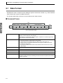
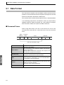
2.1 Data Format
Hexadecimal values are expressed by adding the prefix H’ before the number, e.g., H’02. Numbers
shown without the H’ prefix are ASCII characters.
The number underneath each item in a frame indicates the number of bytes.
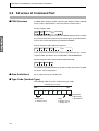
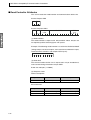
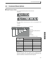
■ Command Frame
Text
Node number Sub-address SID
STX
1
0
2
0
2
BCC
Command text
0
1
BCC calculation range
ETX
1
1
STX
This code (H’02) indicates the beginning of the communications frame (text).
Always set this character in the first byte.
When STX is received again during reception, reception is carried out again from
the point where STX was received.
Node number
•
•
•
•
Sub-address
The sub-address is not used in the E5CN. Be sure to set the sub-address to “00.”
SID (Service ID)
The service ID is not used in the E5CN. Be sure to set the service ID to “00.”
Command text
This is the command text area. For details, see 2.2 Structure of Command Text.
ETX
This code (H’03) indicates the end of the text.
BCC
This is the Block Check Character.
The BCC result is found by calculating the exclusive OR of the bytes from the node
number up to ETX.
2-2
This number specifies the transmission’s destination.
Specify the E5CN’s communications unit number.
A BCD value between 00 and 99 or an ASCII value of XX can be set.
Specify “XX” for a broadcast transmission. No responses will be returned for
broadcast transmissions.
• No responses will be returned from node numbers other than the ones in the
above range.
2.1 Data Format
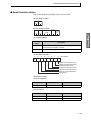
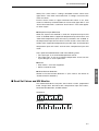
● BCC Calculation Example
The BCC (Block Check Character) is determined by calculating the
exclusive OR of the bytes from the node number up to ETX. The 8-bit
result is written to the BCC byte at the end of the frame.
STX
SID
Node number Sub-address
Command text
02H 0 (30H) 0 (30H) 0 (30H) 0 (30H) 0 (30H) 0 (30H)5 (35H) 0 (30H)3 (33H)
ETX
BCC
03H
35H
BCC = 30H+30H+30H+30H+30H+30H+35H+30H+33H+03H = 35H
The result of the calculation (35 hex) is written to the BCC byte.
The + symbols indicate XOR (exclusive OR) operations.
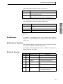
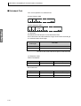
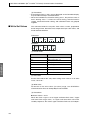
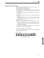
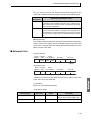
■ Response Frame
Node number
Sub-address
STX
1
End
code
0
2
End code
BCC
Command text
0
2
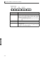
Name
ETX
2
1
1
Error
detection
priority
Description
00
Normal completion
The command ended normally without error.
None
0F
FINS command error
The specified FINS command could not be executed.
The FINS response code should indicate why the command
could not be executed.
8
10
Parity error
The sum total of bits whose received data is “1” does not
match the set value of the “communications parity” bit.
2
11
Framing error
Stop bit is “0.”
1
12
Overrun error
An attempt was made to transfer new data when the reception data buffer was already full.
3
13
BCC error
The calculated BCC value is different from the received
BCC value.
5
14
Format error
• The command text contains characters other than 0 to 9,
and A to F. This error does not apply to Echoback Tests.
(Refer to the Echoback Test for details.)
• There was no SID and command text. There was no command text.
• “MRC/SRC” not included in command text.
7
16
Sub-address error
• Illegal (unsupported) sub-address
• There was no sub-address, SID, and command text.
• Sub-address was less than two characters, and there was
no SID and command text
6
18
Frame length error
The received frame exceeds the specified (supported) number of bytes.
4
• An end code is returned for each command frame received that was addressed to the local node.
• No response will be returned unless the frame contained all elements up to the ETX and BCC.
• “Error Detection Priority” indicates the priority when two or more errors occur simultaneously.
2-3
SECTION 2 CompoWay/F Communications Procedures
■ Communications Data
Communications
format
Set (monitor)
values
CompoWay/F
8-digit hexadecimal
Negative values
Decimal point
2’s complement
Decimal point is removed and the result is converted
to hexadecimal.
Example conversion: 105.0 → 1050 → H’0000041A
■ End Code Example
The following examples show the end code when a command did not
end normally.
Example 1) Illegal Sub-address, No SID, and No Command Text
Command
BCC
Node number Sub-address
STX
0
A
EXT
Response
BCC
Node number Sub-address End code
STX
0
A
1
6
EXT
End code is “16” (sub-address error).
The sub-address error code is used because the sub-address error has
a higher error detection priority than the format error.
Example 2) No Command Text
Command
Node number Sub-address SID
STX
0
0
0
BCC
EXT
Response
BCC
Node number Sub-address End code
STX
0
0
1
4
The end code is “14” (format error).
Example 3) No Node Number Provided
Command
BCC
STX
EXT
The node number is lacking one character.
Response
There is no response.
2-4
EXT
2.1 Data Format
Example 4) No Sub-address and Illegal BCC
Command
BCC
Node number
STX
EXT
Err
Response
Node number Sub-address
STX
0
0
BCC
End code
1
3
EXT
The sub-address is “00” and the end code is “13” (BCC error).
2-5
SECTION 2 CompoWay/F Communications Procedures
2.2 Structure of Command Text
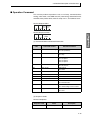
■ PDU Structure
An MRC (Main Request Code) and SRC (Sub-Request Code) followed
by the various required data is transferred to the command text.
Service Request PDU
MRC SRC
Data
The MRES (Main Response Code) and SRES (Sub-Response Code)
are transferred to the response frame following the above MRC/SRC.
Data is then transferred following the MRES and SRES.
Service Response PDU (Normal Response)
Data
MRC SRC MRES SRES
If the specified command text could not be executed, the service
response PDU will contain only the MRC/SRC and MRES/SRES.
Service Response PDU (Command Text Not Executed)
MRC SRC MRES SRES
The MRES and SRES become the response code when processing did
not end in “normal completion.”
■ Area Definitions
Areas comprise only the variable area.
■ Type Code (Variable Type)
The following tables show the variable area type codes.
Variable type (1 byte)
MSB
1
LSB
1
0
Access size
11: Double word
2-6
0
0
0
Area
0: Setup area 0
1: Setup area 1
Read/Write
0: Read only
1: Read/Write
2.2 Structure of Command Text
The following table summarizes setup areas 0 and 1.
Area
Description
Setup area 0
This area groups together the protect, manual control, operation, and adjustment levels.
Setup area 1
This area groups together the initial setting, communications
setting, advanced function setting, and calibration levels.
The variable type is converted to 2-byte ASCII and loaded to the frame.
The following table shows the available variable types.
Variable type
Description
C0
Double-word data. R/O (read only) parameter for setup
area 0.
C1
Double-word data. R/W parameter for setup area 0.
C3
Double-word data. R/W parameter for setup area 1.
* Setup area 1 has no read-only parameters, so there is no variable
type “C2.”
■ Addresses
An address is appended to each of the variable types. Express
addresses in 2-byte hexadecimal and append them for the specified
access size.
■ Number of Elements
The number of elements is expressed in 2-byte hexadecimal. Specify
the number of elements within the range “0 to 2.”
For example, when the number of elements is “0002,” this specifies two
items of data from the address.
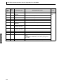
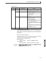
■ List of Services
MRC
SRC
Name of service
Processing
01
01
Read Variable Area
This service reads from variable areas.
01
02
Write Variable Area
This service writes to variable areas.
05
03
Read Controller
Attributes
This service reads the model number
and communications buffer size.
06
01
Read Controller Status
This service reads the operating status.
08
01
Echoback Test
This service performs an echoback
test.
30
05
Operation Command
This service performs operations such
as executing/stopping AT (auto-tuning)
and moving to Setup Area 1.
2-7
SECTION 2 CompoWay/F Communications Procedures
* No commands will be accepted and no responses will be returned
when a memory error (RAM error) has occurred or the Controller is
initializing (until the Controller recognizes the process value after the
power is turned ON).
2-8
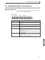
2.3 Detailed Description of the Services
2.3 Detailed Description of the Services
■ Read Variable Area
This service reads data from a variable area.
Service Request PDU
MRC SRC
Variable
type
Read
start address
2
4
0 1 0 1
2
2
Bit
position
Number of
elements
0 0
2
4
Service Request PDU
MRC SRC
0 1 0 1
2
2
Response
code
Read data (for number
of elements)
4
0, 8, or 16
(1) Variable Type and Read Start Address
For details on variable types and read start addresses, see SECTION 3
Communications Data for CompoWay/F and SYSWAY.
(2) Bit Position
The E5CN does not support bit access. Fixed to “00.”
(3) Number of Elements
Number of
elements
Processing
0000
The read operation is not performed (read data is not
appended to the service response PDU), and processing
ends in “normal completion.”
0001 to 0002
The read operation is performed, and processing ends in
“normal completion.”
(4) Response Code
Normal Completion
Response code
0000
Name
Normal completion
Description
No errors were found.
Error Occurred
Response code
Error name
Cause
1001
Command too long
The command is too long.
1002
Command too short
The command is too short.
1101
Area type error
The variable type is wrong.
1103
Start address out-ofrange error
The read start address is out
of range.
2-9
SECTION 2 CompoWay/F Communications Procedures
Response code
Error name
Cause
110B
Response too long
The number of elements is
larger than “0002.”
1100
Parameter error
Bit position is not “00.”
2203
Operation error
EEPROM error
(5) Precautions
● Alarm Function
Even though alarms are not displayed on the Controller’s display, they
function normally in communications.
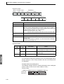
■ Write Variable Area
This service writes data to a variable area.
Service Request PDU
MRC SRC
Variable
type
Start
write address
2
4
0 1 0 2
2
2
Bit
position
0 0
2
Write Data (for
Number of
elements number of elements)
4
0, 8, or 16
Service Response PDU
MRC SRC Response
code
0 1 0 2
2
2
4
(1) Variable Type and Write Start Address
For details on variable types and write start addresses, see SECTION 3
Communications Data for CompoWay/F and SYSWAY.
(2) Bit Position
The E5CN does not support bit access. Fixed to “00.”
(3) Number of Elements
Number of
elements
Processing
0000
The write operation is not performed (do not append write
data to the service request PDU) and processing ends in
“normal completion.”
0001 to 0002
The write operation is performed and processing ends in
“normal completion.”
(4) Response Code
Normal Completion
Response code
0000
2-10
Name
Normal completion
Description
No errors were found.
2.3 Detailed Description of the Services
Error Occurred
Response code
Error name
Cause
1002
Command too
short
The command is too short.
1101
Area type error
The variable type is wrong.
1103
Start address outof-range error
Write start address is out of range.
1104
End address outof-range error
The write end address (write start
address + number of elements)
exceeds the final address of the variable area.
1003
Number of elements/data mismatch
The number of data does not match
the number of elements.
1100
Parameter error
• Bit position is not “00.”
• The write data is out of the setting
range.
3003
Read-only error
Variable type “C0” was written to.
2203
Operation error
• The “communications writing”
parameter is set to “OFF” (disabled).
• Write operation was performed on
the parameters from setup area 0
to setup area 1.
• Write operation was performed on
a protected parameter other than in
the protect level.
• AT (auto-tuning) was in progress.*
• EEPROM error
* For details on AT (auto-tuning), refer to the separate User’s Manuals.
(5) Precautions
● Alarm Function
Even though alarms are not displayed on the Controller’s display, they
function normally in communications.
2-11
SECTION 2 CompoWay/F Communications Procedures
■ Read Controller Attributes
This service reads the model number and communications buffer size.
Service Request PDU
MRC SRC
0 5 0 3
2
2
Service Response PDU
MRC SRC
0 5 0 3
2
2
Response
code
Model No.
4
10
Buffer
size
0 0 2 8
4
(1) Model Number
The model number is expressed in 10-byte ASCII. When 10 bytes are
not required, pad the remaining bytes with spaces.
Example: The following model number is used for the E5CN-Q2HH03T
(voltage output, two alarm outputs, two heater burnout detection inputs,
communications functions, and multiple TC/Pt inputs).
e 5 c n - Q 2 H H O
(2) Buffer Size
The communications buffer size is expressed in 2-byte hexadecimal,
and read after being converted to 4-byte ASCII.
Buffer size: 40 bytes (= H’0028)
(3) Response Code
Normal Completion
Response code
0000
Name
Normal completion
Description
No errors were found.
Error Occurred
Response code
2-12
Name
Description
1001
Command too long
The command is too long.
2203
Operation error
EEPROM error
2.3 Detailed Description of the Services
■ Read Controller Status
This service reads the operating status and error status.
Service Request PDU
MRC SRC
0 6 0 1
2
2
Service Response PDU
MRC SRC
0 6 0 1
2
2
Response
code
Operating Related
status informa-
tion
4
2
2
(1) Operating Status
Operating
status
Description
00
Control is being carried out (error has not occurred in setup
area 0 and the Controller is running).
01
Control is not being carried out (state other than above).
(2) Related Information
7
6
5
4
3
2
1
0
Bit position
0
Heater overcurrent (CT1)
Heater current hold (CT1)
Heater burnout error
Heater overcurrent (CT2)
Heater current hold (CT2)
Display range exceeded
Input error
(3) Response Code
Normal Completion
Response code
0000
Name
Normal completion
Description
No errors were found.
Error Occurred
Response code
Name
Description
1001
Command too long
The command is too long.
2203
Operation error
EEPROM error
2-13
SECTION 2 CompoWay/F Communications Procedures
■ Echoback Test
This service performs an echoback test.
Service Request PDU
MRC SRC
Test data
0 8 0 1
2
2
0 to 23
Service Response PDU
MRC SRC
0 8 0 1
2
2
Response
code
Test data
0 to 23
(1) Test Data
Set between 0 and 23 bytes of user-defined test data.
Set a value for the test data within the ranges shown below according to
the communications data length.
Communications
data length
Test Data
8 bits
ASCII data: H’20 to H’7E or H’A1 to H’FE
7 bits
ASCII data: H’20 to H’7E
Do not set the value H’40. No response will be returned.
(2) Response Code
Normal Completion
Response code
0000
Name
Normal completion
Description
No errors were found.
Error Occurred
Response code
2-14
Name
Description
1001
Command too long
The command is too long.
2203
Operation error
EEPROM error
2.3 Detailed Description of the Services
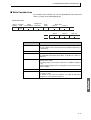
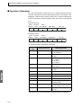
■ Operation Command
This service performs operations such as run/stop, communications
writing, write mode, save RAM data, AT (auto-tuning) execution/cancel,
multi-SP, move protect level, move to setup area 1, and software reset.
Service Request PDU
MRC SRC
3 0 0 5
2
2
Com- Related
mand informacode
tion
2
2
Service Response PDU
MRC SRC Response
code
3 0 0 5
2
2
4
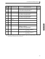
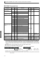
(1) Command Code and Related Information
Command
code
Command content
Related Information
00
Communications writing
00: OFF (disabled)
01: ON (enabled)
01
RUN/STOP
00: Run
01: Stop
02
Multi-SP
00: Set point 0
01: Set point 1
02: Set point 2
03: Set point 3
03
AT execute/cancel
00: Cancel
01: AT execute
04
Write mode
00: Backup
01: RAM
05
Save RAM data
00
06
Software reset (See note.)
00
07
Move to setup area 1
00
08
Move to protect level
00
09
Auto/manual switch
00: Automatic mode
01: Manual mode
0B
Parameter initialization
00: Initialize to defaults
01: Initial settings service values
11
Program start
00: Reset
01: Start
Note: No response will be returned when a software reset is carried out.
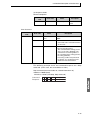
(2) Response Code
Normal Completion
Response code
0000
Name
Normal completion
Description
No errors were found.
2-15
SECTION 2 CompoWay/F Communications Procedures
Error Occurred
Response code
Error name
Cause
1001
Command too long
The command is too long.
1002
Command too short
The command is too short.
1100
Parameter error
Command code and related
information are wrong.
2203
Operation error
• The “communications writing” parameter is set to
“OFF” (disabled). The command is received regardless
of the “communications writing” parameter setting (ON/
OFF).
• Processing could not be performed. For details, see (3)
Operation Commands and
Precautions below.
• EEPROM error
(3) Operation Commands and Precautions
● Communications Writing
Set the “communications writing” parameter to “ON: enabled” or “OFF:
disabled” with the related information setting. The setting can be
accepted in both setup area 0 and setup area 1.
● RUN/STOP
Set control to “run” or “stop” with the related information setting. The
setting can be accepted in both setup area 0 and setup area 1.
● Multi-SP
Set four set points beforehand in the adjustment level so that you can
switch to a desired set point. The setting can be accepted in both setup
area 0 and setup area 1.
● AT Execute/Cancel
Set AT (auto-tuning) to “execute” or “cancel” with the related information
setting. This command can be accepted in setup area 0 only. An
“operation error” will be generated in the following instances:
• When the “run/stop” parameter is set to “stop”
• When the command is executed in “setup area 1”
• When ON/OFF control is being used
● Write Mode
Set either the backup mode or RAM write mode with the related information setting. The setting can be accepted in both setup area 0 and
setup area 1.
2-16
2.3 Detailed Description of the Services
Write mode
Description
Backup mode
The data is written to EEPROM when the parameters in the operation/adjustment levels (excluding
read-only parameters) are written by communications.
RAM write mode
The data is not written to EEPROM when the parameters in the operation/adjustment levels (excluding
read-only parameters) are written by communications. Parameters can be changed by operating the
keys on the front panel of the controller.
• When the mode is switched from RAM write mode to backup mode, the
parameters in the operation/adjustment levels (excluding read-only
parameters) are written to EEPROM.
• The RAM write mode is enabled only when the “communications
writing” parameter is set to “ON” (enabled).
Consequently, when the “communications writing” parameter setting is
changed to “OFF” (disabled), the parameters in the operation/
adjustment levels (excluding read-only parameters) are written to
EEPROM even if the mode is set to RAM write mode.
● Save RAM Data
This command writes the parameters in the operation/adjustment levels
(excluding read-only parameters) to EEPROM. The setting can be
accepted in both setup area 0 and setup area 1.
● Software Reset
Restarts processing from the point when power is turned ON. The
setting can be accepted in both setup area 0 and setup area 1. No
response will be returned for this operation command.
● Move to Setup Area 1
This command moves to “setup area 1” and can be accepted at both
setup areas 0 and 1. If the “initial setup/communications protection” is
set to “2,” an “operation error” will be generated, and the move to setup
area 1 will be prohibited.
When this move is carried out from setup area 0, the display indicates
the “input type” in the “initial setting level.” When this operation
command is executed in setup area 1, the display will not change.
◆ Moving to Setup Area 1 in Manual Mode
When this operation command is issued in manual mode, an
“operation error” will be generated, and the move to setup area 1 will
be prohibited.
2-17
SECTION 2 CompoWay/F Communications Procedures
● Move to Protect Level
This command moves to the “protect level” and can be accepted only in
setup area 0.When this command is issued in setup area 1, an
“operation error” will be generated, and the move to the protect level will
be prohibited.
◆ Moving to Protect Level in Manual Mode
When this operation command is issued in manual mode, an
“operation error” will be generated, and the move to the protect level
will be prohibited.
● Auto/Manual Switch
This operation command switches the mode to manual mode or
automatic mode, based on the related information setting. This
command can be accepted in setup area 0 only. An “operation error”
will be generated in the following instances:
• When the command is executed in “setup area 1"
• When auto/manual switching is disabled (not displayed)
When the Controller is switched to manual mode, the “manual manipulated variable” will be displayed. When the Controller is switched from
manual mode to automatic mode, the operation level’s first parameter
will be displayed. When the Controller is switched to manual mode
while already in manual mode, the command will be completed
normally and the display will not change (the contents will not be
refreshed).
◆ Writing Auto/Manual Status in EEPROM
The write mode determines whether the auto/manual status is written
to EEPROM.
Write mode
Description
Backup mode
When the auto/manual mode is switched by
communications, the auto/manual status is written to EEPROM.
RAM write mode
When the auto/manual mode is switched by
communications, the auto/manual status is not
written to EEPROM.
The status can be written with the Controller
key operation.
* When the auto/manual mode is switched with an operation
command through communications and the Controller is in RAM
write mode, the auto/manual status is not stored in EEPROM.
Consequently, if the Controller is restar ted by performing a
software reset or turning the power OFF and ON again, the auto/
manual mode is set to the last saved status.
2-18
2.3 Detailed Description of the Services
◆ Switching to Manual Mode during Auto-tuning
If the mode is switched during auto-tuning (AT), the AT will be
cancelled and the Controller will be switched to manual mode.
● Parameter Initialization
The present settings are returned to the default values and written to
EEPROM. This command can be accepted in setup area 1 only. When
this command is issued in setup area 0, an “operation error” will be
generated.
The set values that are set during initialization depend on the
command’s related information setting, as shown in the following table.
Related
information
Explanation (initialization values)
00
Default initialization values (See SECTION 3 Communications Data for CompoWay/F and SYSWAY for details.)
(These settings are the same as the ones used when
“FACT” is selected for the setting data’s set value initialization.)
01
Values set with the initial values setting service
(These settings are the same as the ones used when
“USER” is selected for the setting data’s set value initialization.)
If the initial values have not been set yet with the initial
values setting service, the default initial values will be set.
● Program Start
The simple program function can be reset/started with the related information setting. The setting can be accepted in both setup area 0 and
setup area 1. An operation error will be generated if program start has
been set in the event input.
2-19
SECTION 2 CompoWay/F Communications Procedures
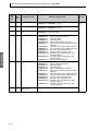
2.4 Response Code List
Normal Completion
Response
code
0000
Name
Normal completion
Error
detection
priority
Description
No errors were found.
None
Error Occurred
Response
code
Name
Error
detection
priority
Description
0401
Unsupported command
The service function for the relevant command is
not supported.
1
1001
Command too long
The command is too long.
2
1002
Command too short
The command is too short.
3
1101
Area type error
Wrong variable type
4
1103
Start address out-of-range error
The read/write start address is out of range.
5
1104
End address out-of-range error
The write end address (write start address +
number of elements) exceeds the final address
of the variable area.
6
1003
Number of elements/data mismatch
The amount of data does not match the number
of elements.
7
110B
Response too long
The response exceeds the communications
buffer size (when the number of elements is
larger than 0002).
8
1100
Parameter error
• Bit position is not “00.”
• The write data is out of the setting range.
• The command code or related information in
the operation command is wrong.
9
3003
Read-only error
Variable type “C0” was written to.
10
2203
Operation error
• The “communications writing” parameter is set
to “OFF” (disabled).
• Write operation was performed on the parameters from setup area 0 to setup area 1.
• Write operation was performed on a protected
parameter other than in the protect level.
• Writing was carried out during AT execution.
• Processing is not possible by operation command.
• EEPROM error
11
2-20
SECTION 3
Communications Data for
CompoWay/F and SYSWAY
This s ecti on li sts the de tails of th e co mmun ica tions data i n the
CompoWay/F and SYSWAY communications protocols.
3.1
3.2
Variable Area (Setting Range) List ............................... 3-2
Status.......................................................................... 3-15
3-1
SECTION 3 Communications Data for CompoWay/F and SYSWAY
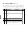
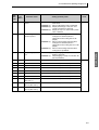
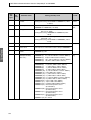
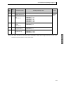
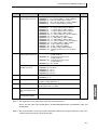
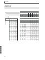
3.1 Variable Area (Setting Range) List
The following table lists the variable areas. Items expressed in hexadecimal in the “Set (monitor) value”
column are the setting range for CompoWay/F communications. The values in parentheses are the
actual setting range. Use the values in parentheses as the setting range for SYSWAY communications.
Com Data
When there is a section reference for a setting item, refer to that reference for details.
Variable
type
Address
C0
0000
PV
Temperature: Use the specified range for each sensor.
Analog: Scaling lower limit −5% FS to Scaling
upper limit +5% FS
C0
0001
Status (See note 1.)
See 3.2 Status for details.
C0
0002
Internal set point
(See note 1.)
SP lower limit to SP upper limit
C0
0003
Heater current 1 value
monitor
H'00000000 to H'00000226 (0.0 to 55.0)
C0
0004
MV monitor (heating)
Standard: H'FFFFFFCE to H'0000041A
(−5.0 to 105.0)
Heating and cooling: H'00000000 to H'0000041A
(0.0 to 105.0)
C0
0005
MV monitor (cooling)
H'00000000 to H'0000041A (0.0 to 105.0)
C0
0006
Heater current value 2
monitor
H'00000000 to H'00000226 (0.0 to 55.0)
C0
0007
Leakage current value 1
monitor
H'00000000 to H'00000226 (0.0 to 55.0)
C0
0008
Leakage current value 2
monitor
H'00000000 to H'00000226 (0.0 to 55.0)
C0
0009
Soak time remain monitor
H'00000000 to H'0000270F (0 to 9999)
3-2
Parameter name
Setting (monitor) value
Level
Operating
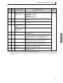
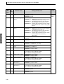
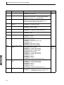
3.1 Variable Area (Setting Range) List
Address
Parameter name
Setting (monitor) value
C1
0000
Operation/adjustment
protect
H'00000000 (0): No restrictions in operation and adjustment levels
H'00000001 (1): Move to adjustment level is prohibited.
H'00000002 (2): Display and change of only “PV” and
“PV/SP” parameters is allowed.
H'00000003 (3): Display of only “PV” and “PV/SP” parameters is allowed.
C1
0001
Initial setting/communications protect
H'00000000 (0): Move to initial setting/communications
setting level is allowed. (Move to
advanced function setting level is displayed.)
H'00000001 (1): Move to initial setting/communications
setting level is allowed. (Move to
advanced function setting level is not displayed.)
H'00000002 (2): Move to initial setting/communications
setting level is prohibited.
C1
0002
Setup change protection
H'00000000 (0): OFF (Changing of setup on Controller
display is allowed.)
H'00000001 (1): ON (Changing of setup on Controller display is prohibited.)
C1
0003
Set point
SP lower limit to SP upper limit
C1
0004
Alarm value 1
H'FFFFF831 to H'0000270F (−1999 to 9999)
C1
0005
Upper-limit alarm 1
H'FFFFF831 to H'0000270F (−1999 to 9999)
C1
0006
Lower-limit alarm 1
H'FFFFF831 to H'0000270F (−1999 to 9999)
C1
0007
Alarm value 2
H'FFFFF831 to H'0000270F (−1999 to 9999)
C1
0008
Upper-limit alarm 2
H'FFFFF831 to H'0000270F (−1999 to 9999)
C1
0009
Lower-limit alarm 2
H'FFFFF831 to H'0000270F (−1999 to 9999)
C1
000A
Alarm value 3
(See note 2.)
H'FFFFF831 to H'0000270F (−1999 to 9999)
C1
000B
Upper-limit alarm
value 3 (See note 2.)
H'FFFFF831 to H'0000270F (−1999 to 9999)
C1
000C
Lower-limit alarm
value 3 (See note 2.)
H'FFFFF831 to H'0000270F (−1999 to 9999)
Level
Protect
Operating
3-3
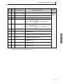
Com Data
Variable
type
SECTION 3 Communications Data for CompoWay/F and SYSWAY
Com Data
Variable
type
Address
Parameter name
Setting (monitor) value
C1
000D
Heater burnout 1
detection
H'00000000 to H'000001F4 (0.0 to 50.0)
C1
000E
Set point 0
SP lower limit to SP upper limit
C1
000F
Set point 1
SP lower limit to SP upper limit
C1
0010
Set point 2
SP lower limit to SP upper limit
C1
0011
Set point 3
SP lower limit to SP upper limit
C1
0012
Temperature input
shift value
H'FFFFF831 to H'0000270F (−199.9 to 999.9)
C1
0013
Upper-limit temperature input shift value
H'FFFFF831 to H'0000270F (−199.9 to 999.9)
C1
0014
Lower-limit temperature input shift value
H'FFFFF831 to H'0000270F (−199.9 to 999.9)
C1
0015
Proportional band
H'00000001 to H'0000270F (0.1 to 999.9)
C1
0016
Integral time
H'00000000 to H'00000F9F (0 to 3999)
C1
0017
Derivative time
H’00000000 to H’00000F9F (0 to 3999) (Range when RT is
“OFF”)
H’00000000 to H’0000270F (0.0 to 999.9) (Range when
RT is “ON”)
C1
0018
Cooling coefficient
H'00000001 to H'0000270F (0.01 to 99.99)
3-4
Level
Adjustment
3.1 Variable Area (Setting Range) List
Address
Parameter name
Setting (monitor) value
C1
0019
Dead band
H'FFFFF831 to H'0000270F
(−199.9 to 999.9 for TC/Pt multi-input models)
(−19.9 to 99.99 for Analog input models)
C1
001A
Manual reset value
H'00000000 to H'000003E8 (0.0 to 100.0)
C1
001B
Hysteresis (heating)
H'00000001 to H'0000270F
(0.1 to 999.9 for TC/Pt multi-input models)
(0.01 to 99.99 for Analog input models)
C1
001C
Hysteresis (cooling)
H'00000001 to H'0000270F
(0.1 to 999.9 for TC/Pt multi-input models)
(0.01 to 99.99 for Analog input models)
C1
001D
Heater burnout 2
detection
H'00000000 to H'000001F4 (0.0 to 50.0)
C1
001E
HS alarm 1
H'00000000 to H'000001F4 (0.0 to 50.0)
C1
001F
HS alarm 2
H'00000000 to H'000001F4 (0.0 to 50.0)
C1
0020
Soak time
H'00000001 to H'0000270F (1 to 9999)
C1
0021
Wait band
H'00000000 (0): OFF
H'00000001 to H'0000270F
(0.1 to 999.9 for TC/Pt multi-input models)
(0.01 to 99.99 for Analog input models)
C1
0022
MV at stop
Standard: H'FFFFFFCE to H'0000041A (−5.0 to 105.0)
Heating and cooling: H'FFFFFBE6 to H'0000041A
(−105.0 to 105.0)
C1
0023
MV at PV error
Standard: H'FFFFFFCE to H'0000041A (−5.0 to 105.0)
Heating and cooling: H'FFFFFBE6 to H'0000041A
(−105.0 to 105.0)
Level
Adjustment
Com Data
Variable
type
Note: The alarm function can also be used in Controllers without alarm output terminals. In this case,
confirm alarm occurrences via the status data.
3-5
Com Data
SECTION 3 Communications Data for CompoWay/F and SYSWAY
Variable
type
Address
C1
0024
Manual manipulated
variable
Standard: H'FFFFFFCE to H'0000041A (−5.0 to 105.0)
Heating and cooling: H'FFFFFBE6 to H'0000041A (−105.0
to 105.0)
Manual
Control
C1
0025
SP ramp set value
H'00000000 (0): OFF
H'00000001 to H'0000270F (1 to 9999)
Adjustment
C1
0026
MV upper limit
Standard: MV lower limit + 0.1 to H’0000041A (MV lower
limit + 0.1 to 105.0)
Heating and cooling: H'00000000 to H'0000041A (0.0 to
105.0)
C1
0027
MV lower limit
Standard: H’FFFFFFCE to MV upper limit − 0.1 (−5.0 to MV
upper limit − 0.1)
Heating and cooling: H'FFFFFBE6 to H'00000000 (−105.0
to 0.0)
C1
0028
Move protect level
H'FFFFF831 to H'0000270F (−1999 to 9999)
C1
0029
Password to move to
protect level
H'FFFFF831 to H'0000270F (−1999 to 9999)
(Can only be set. The monitor value is always H’00000000.)
C1
002A
Parameter mask
enable
H'00000000 (0): OFF
H'00000001 (1): ON
C3
0000
Input type (TC/Pt
multi-input models)
(See note.)
H'00000000 (0):
H'00000001 (1):
H'00000002 (2):
H'00000003 (3):
H'00000004 (4):
Parameter name
Setting (monitor) value
H'00000005 (5):
H'00000006 (6):
H'00000007 (7):
H'00000008 (8):
H'00000009 (9):
H'0000000A (10):
H'0000000B (11):
H'0000000C (12):
H'0000000D (13):
H'0000000E (14):
H'0000000F (15):
H'00000010 (16):
H'00000011 (17):
H'00000012 (18):
H'00000013 (19):
Pt (−200 to 850°C/−300 to 1500°F)
Pt (−199.9 to 500.0°C/−199.9 to 900.0°F)
Pt (0.0 to 100.0°C/0.0 to 210.0°F)
JPt (−199.9 to 500.0°C/−199.9 to 900.0°F)
JPt (0.0 to 100.0°C/0.0 to 210.0°F)
K (−200 to 1300°C/−300 to 2300°F)
K (−20.0 to 500.0°C/0.0 to 900.0°F)
J (−100 to 850°C/−100 to 1500°F)
J (−20.0 to 400.0°C/0.0 to 750.0°F)
T (−200 to 400°C/−300 to 700°F)
T (−199.9 to 400.0°C/−199.9 to 700.0°F)
E (0 to 600°C/0 to 1100°F)
L (−100 to 850°C/−100 to 1500°F)
U (−200 to 400°C/−300 to 700°F)
U (−199.9 to 400.0°C/−199.9 to 700.0°F)
N (−200 to 1300°C/−300 to 2300°F)
R (0 to 1700°C/0 to 3000°F)
S (0 to 1700°C/0 to 3000°F)
B (100 to 1800°C/300 to 3200°F)
Infrared temperature sensor
(K 140°F/60°C)
H'00000014 (20): Infrared temperature sensor
(K 240°F/120°C)
H'00000015 (21): Infrared temperature sensor
(K 280°F/140°C)
H'00000016 (22): Infrared temperature sensor
(K 440°F/220°C)
H'00000017 (23): 0 to 50 mV
3-6
Level
Protect
Initial setting
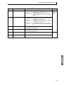
3.1 Variable Area (Setting Range) List
Address
C3
0000
Input type (analog
input models) (See
note.)
H'00000000 (0): 4 to 20 mA
H'00000001 (1): 0 to 20 mA
H'00000002 (2): 1 to 5 V
H'00000003 (3): 0 to 5 V
H'00000004 (4): 0 to 10 V
C3
0001
Scaling upper limit
Scaling lower limit + 1 to H’0000270F (scaling lower limit + 1
to 9,999)
C3
0002
Scaling lower limit
H’FFFFF831 to Scaling upper limit − 1 (−1999 to Scaling
upper limit − 1)
C3
0003
Decimal point position (TC/Pt multi-input
models)
H'00000000 to 00000001 (0 to 1)
Decimal point position (analog input
models)
H'00000000 to 00000003 (0 to 3)
Parameter name
Setting (monitor) value
C3
0004
Temperature unit
H'00000000 (0): °C
H'00000001 (1): °F
C3
0005
SP upper limit
The range of values (without decimal point) is as follows:
Temperature: SP lower limit + 1 to Input range upper limit
Analog: SP lower limit + 1 to Scaling upper limit
C3
0006
SP lower limit
The range of values (without decimal point) is as follows:
Temperature: Input range lower limit to SP upper limit − 1
Analog: Scaling lower limit to SP upper limit − 1
C3
0007
PID/OnOff
H'00000000 (0): ON/OFF
H'00000001 (1): 2 degrees of freedom PID control
C3
0008
Standard or heating
and cooling
H'00000000 (0): Standard
H'00000001 (1): Heating and cooling
C3
0009
ST
H'00000000 (0): OFF
H'00000001 (1): ON
Level
Initial setting
Com Data
Variable
type
Note:The input type can be selected to match the connected sensor.
There are two input type specifications: Thermocouple/Resistance thermometer input and Analog
input.
3-7
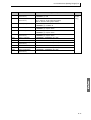
Com Data
SECTION 3 Communications Data for CompoWay/F and SYSWAY
Variable
type
Address
C3
000A
Control period (heat)
H'00000000 (0): 0.5
H'00000001 to H'00000063 (1 to 99)
C3
000B
Control period (cool)
H'00000000 (0): 0.5
H'00000001 to H'00000063 (1 to 99)
C3
000C
Direct/reverse operation
H'00000000 (0): Reverse operation
H'00000001 (1): Direct operation
C3
000D
Alarm 1 type
H'00000000 (0):
H'00000001 (1):
H'00000002 (2):
H'00000003 (3):
H'00000004 (4):
H'00000005 (5):
C3
000E
Alarm 2 type
H'00000000 (0):
H'00000001 (1):
H'00000002 (2):
H'00000003 (3):
H'00000004 (4):
H'00000005 (5):
C3
000F
Alarm 3 type
(See note 2.)
Same settings as the alarm 2 type
3-8
Parameter name
Setting (monitor) value
Alarm function OFF
Upper and lower-limit alarm
Upper-limit alarm
Lower-limit alarm
Upper and lower-limit range alarm
Upper and lower-limit alarm with standby
sequence
H'00000006 (6): Upper-limit alarm with standby sequence
H'00000007 (7): Lower-limit alarm with standby sequence
H'00000008 (8): Absolute-value upper-limit alarm
H'00000009 (9): Absolute-value lower-limit alarm
H'0000000A (10): Absolute-value upper-limit alarm with
standby sequence
H'0000000B (11): Absolute-value lower-limit alarm with
standby sequence
H'0000000C (12): LBA (Loop Burnout Alarm)
Alarm function OFF
Upper and lower-limit alarm
Upper-limit alarm
Lower-limit alarm
Upper and lower-limit range alarm
Upper and lower-limit alarm with standby
sequence
H'00000006 (6): Upper-limit alarm with standby sequence
H'00000007 (7): Lower-limit alarm with standby sequence
H'00000008 (8): Absolute-value upper-limit alarm
H'00000009 (9): Absolute-value lower-limit alarm
H'0000000A (10): Absolute-value upper-limit alarm with
standby sequence
H'0000000B (11): Absolute-value lower-limit alarm with
standby sequence
Level
Initial setting
3.1 Variable Area (Setting Range) List
Address
C3
0010
Communications unit
number (See note 3.)
H'00000000 to H'00000063 (0 to 99)
C3
0011
Communications baud
rate
(See note 3.)
H'00000000 (0): 1.2
H'00000001 (1): 2.4
H'00000002 (2): 4.8
H'00000003 (3): 9.6
H'00000004 (4): 19.2
H'00000005 (5): 38.4
C3
0012
Communications data
length
(See note 3.)
H'00000007 (7): 7
H'00000008 (8): 8
C3
0013
Communications stop
bits (See note 3.)
H'00000001 (1): 1
H'00000002 (2): 2
C3
0014
Communications parity (See note 3.)
H'00000000 (0): None
H'00000001 (1): Even
H'00000002 (2): Odd
Parameter name
Setting (monitor) value
Level
Communications
setting
Note: The alarm function can also be used in Controllers without alarm output terminals. In this case,
confirm alarm occurrences via the status data.
3-9
Com Data
Variable
type
Com Data
SECTION 3 Communications Data for CompoWay/F and SYSWAY
Varia
ble
type
Address
C3
0015
Number of multi-SP
uses
H'00000000 (0): No multi-SP
H'00000001 (1): 2SP
H'00000002 (2): 4SP
C3
0016
Event input assignment 1
H'00000000 (0): None
H'00000001 (1): RUN/STOP (Cannot be set if the “Number
of multi-SP uses” is set to 1 or 2.)
H'00000002 (2): Auto/Manual (Cannot be set if the “Number of multi-SP uses” is set to 1 or 2.)
H'00000003 (3): Program Start (Cannot be set if the “Number of multi-SP uses” is set to 1 or 2.) (See
note 6.)
C3
0017
Event input assignment 2
H'00000000 (0): None
H'00000001 (1): RUN/STOP (Cannot be set if the “Number
of multi-SP uses” is set to 2.)
H'00000002 (2): Auto/Manual (Cannot be set if the “Number of multi-SP uses” is set to 2.)
H'00000003 (3): Program Start (Cannot be set if the “Number of multi-SP uses” is set to 2.)
(See note 6.)
C3
001A
Multi-SP usage
H'00000000 (0): OFF
H'00000001 (1): ON
C3
001B
SP ramp time unit
H'00000000 (0): EU/second
H'00000001 (1): EU/minute
C3
001C
SP ramp set value
H'00000000 (0): OFF
H'00000001 to H'0000270F (1 to 9999)
C3
001D
Standby sequence
reset
H'00000000 (0): Condition A
H'00000001 (1): Condition B
C3
001E
Alarm 1 open in alarm
H'00000000 (0): Close in alarm
H'00000001 (1): Open in alarm
C3
001F
Alarm 1 hysteresis
H'00000001 to H'0000270F
(0.1 to 999.9 for TC/Pt multi-input models)
(0.01 to 99.99 for Analog input models)
C3
0020
Alarm 2 open in alarm
H'00000000 (0): Close in alarm
H'00000001 (1): Open in alarm
C3
0021
Alarm 2 hysteresis
H'00000001 to H'0000270F
(0.1 to 999.9 for TC/Pt multi-input models)
(0.01 to 99.99 for Analog input models)
C3
0022
Alarm 3 open in alarm
(See note 2.)
H'00000000 (0): Close in alarm
H'00000001 (1): Open in alarm
C3
0023
Alarm 3 hysteresis
(See note 2.)
H'00000001 to H'0000270F
(0.1 to 999.9 for TC/Pt multi-input models)
(0.01 to 99.99 for Analog input models)
C3
0024
HB ON/OFF
H'00000000 (0): OFF
H'00000001 (1): ON
C3
0025
Heater burnout latch
H'00000000 (0): OFF
H'00000001 (1): ON
3-10
Parameter name
Setting (monitor) value
Level
Advanced
function
setting
3.1 Variable Area (Setting Range) List
Address
C3
0026
Heater burnout hysteresis
H'00000001 to H'000001F4 (0.1 to 50.0)
C3
0027
ST stable range
H'00000001 to H'0000270F (0.1 to 999.9)
C3
0028
α
H'00000000 to H'00000064 (0.00 to 1.00)
C3
0029
MV upper limit
Standard: MV lower limit + 0.1 to H’0000041A (MV lower
limit + 0.1 to 105.0)
Heating and cooling: H'00000000 to H'0000041A (0.0 to
105.0)
C3
002A
MV lower limit
Standard: H’FFFFFFCE to MV upper limit − 0.1 (−5.0 to MV
upper limit − 0.1)
Heating and cooling: H'FFFFFBE6 to H'00000000 (−105.0
to 0.0)
C3
002B
Input digital filter
H'00000000 to H'0000270F (0.0 to 999.9)
C3
002C
Additional PV display
H'00000000 (0): OFF
H'00000001 (1): ON
C3
002D
MV display
H'00000000 (0): OFF (display of manipulated variable OFF)
H'00000001 (1): ON (display of manipulated variable ON)
C3
002E
Automatic display
return time
H'00000000 (0): OFF
H'00000001 to H'00000063 (1 to 99)
C3
002F
Alarm 1 latch
H'00000000 (0): OFF
H'00000001 (1): ON
C3
0030
Alarm 2 latch
H'00000000 (0): OFF
H'00000001 (1): ON
C3
0031
Alarm 3 latch
(See note 2.)
H'00000000 (0): OFF
H'00000001 (1): ON
Parameter name
Setting (monitor) value
Level
Advanced
function
setting
Com Data
Varia
ble
type
Note: The alarm function can also be used in Controllers without alarm output terminals. In this case,
confirm alarm occurrences via the status data.
3-11
Com Data
SECTION 3 Communications Data for CompoWay/F and SYSWAY
Variable
type
Address
C3
0032
Protect level move
time
H'00000001 to H'0000001E (1 to 30)
C3
0033
Input error output
H'00000000 (0): OFF
H'00000001 (1): ON
C3
0034
Cold junction compensation method
H'00000000 (0): OFF
H'00000001 (1): ON
C3
0035
MB command logic
switching
(See note 7.)
H'00000000 (0): OFF
H'00000001 (1): ON
C3
0036
PV change color
H'00000000 (0): ORG
H'00000001 (1): RED
H'00000002 (2): GRN
H'00000003 (3): R-G
H'00000004 (4): G-R
H'00000005 (5): R-G.R
H'00000006 (6): G-O.R
H'00000007 (7): O-G.R
C3
0037
PV stable band
H'00000001 to H'0000270F
(0.1 to 999.9 for TC/Pt multi-input models)
(0.01 to 99.99 for Analog input models)
C3
0038
Alarm 1 ON delay
H'00000000 to H'000003E7 (0 to 999)
C3
0039
Alarm 2 ON delay
H'00000000 to H'000003E7 (0 to 999)
C3
003A
Alarm 3 ON delay
(See note 2.)
H'00000000 to H'000003E7 (0 to 999)
C3
003B
Alarm 1 OFF delay
H'00000000 to H'000003E7 (0 to 999)
C3
003C
Alarm 2 OFF delay
H'00000000 to H'000003E7 (0 to 999)
C3
003D
Alarm 3 OFF delay
(See note 2.)
H'00000000 to H'000003E7 (0 to 999)
C3
003E
Transfer output type
H'00000000 (0): OFF
H'00000001 (1): Set point
H'00000002 (2): Set point during SP ramp
H'00000003 (3): PV
H'00000004 (4): MV monitor (heating)
H'00000005 (5): MV monitor (cooling)
C3
003F
Transfer output upper
limit
H'FFFFF831 to H'0000270F (−1999 to 9999) (See note 4.)
C3
0040
Transfer output lower
limit
H'FFFFF831 to H'0000270F (−1999 to 9999) (See note 4.)
C3
0041
Linear current output
H'00000000 (0): 4 to 20 mA
H'00000001 (1): 0 to 20 mA
C3
0042
Input shift type
H'00000000 (0): 1-point shift
H'00000001 (1): 2-point shift
C3
0043
Output status during
error
H'00000000 (0): 0 mA
H'00000001 (1): MV at PV error
3-12
Parameter name
Setting (monitor) value
Level
Advanced
function
setting
Initial setting
Advanced
function
setting
3.1 Variable Area (Setting Range) List
Address
C3
0044
Auto/manual switching
display addition
H'00000000 (0): OFF
H'00000001 (1): ON
C3
0045
RT
H'00000000 (0): OFF
H'00000001 (1): ON
C3
0046
HS alarm
H'00000000 (0): OFF
H'00000001 (1): ON
C3
0047
HS alarm latch
H'00000000 (0): OFF
H'00000001 (1): ON
C3
0048
HS alarm hysteresis
H'00000001 to H'000001F4 (0.1 to 50.0)
C3
0049
LBA detection time
H'00000000 to H'0000270F (0 to 9999)
C3
004A
LBA level
H'00000001 to H'0000270F
(0.1 to 999.9 for TC/Pt multi-input models)
(0.01 to 99.99 for Analog input models)
C3
004B
LBA band
H'00000000 to H'0000270F
(0.0 to 999.9 for TC/Pt multi-input models)
(0.00 to 99.99 for Analog input models)
Parameter name
Setting (monitor) value
Level
Advanced
function
setting
Com Data
Variable
type
3-13
Com Data
SECTION 3 Communications Data for CompoWay/F and SYSWAY
Variable
type
Address
C3
004C
Protocol Setting
(See note 3.)
H'00000000 (0): CompoWay/F (SYSWAY)
H'00000001 (1): Modbus
C3
004D
Send data wait time
(See note 3.)
H'00000000 to H'00000063 (0 to 99)
C3
004E
Control output 1
assignment
When control output 1 is a linear output:
H'00000000 (0): Not assigned.
H'00000001 (1): Control output (heating)
H'00000002 (2): Control output (cooling)
When control output 1 is a pulse output:
H'00000000 (0): Not assigned.
H'00000001 (1): Control output (heating)
H'00000002 (2): Control output (cooling)
H'00000003 (3): Alarm 1
H'00000004 (4): Alarm 2
H'00000005 (5): Alarm 3
H'00000006 (6): Program end output (See note 5.)
C3
004F
Control output 2
assignment
H'00000000 (0): Not assigned.
H'00000001 (1): Control output (heating)
H'00000002 (2): Control output (cooling)
H'00000003 (3): Alarm 1
H'00000004 (4): Alarm 2
H'00000005 (5): Alarm 3
H'00000006 (6): Program end output (See note 5.)
C3
0050
Alarm 1 assignment
H'00000000 to H'00000006 (0 to 6)
* Same settings as control output 2 assignments
C3
0051
Alarm 2 assignment
H'00000000 to H'00000006 (0 to 6)
* Same settings as control output 2 assignments
C3
0052
Display character
switch
H'00000000 (0): OFF
H'00000001 (1): ON
C3
0053
Program pattern
H'00000000 (0): OFF
H'00000001 (1): STOP
H'00000002 (2): CONT
Initial setting
C3
0054
Soak time units
H'00000000 (0): Minutes
H'00000001 (1): Hours
C3
0055
Alarm SP selection
H'00000000 (0): Set point during SP ramp
H'00000001 (1): Set point
Advanced
function
setting
Parameter name
Setting (monitor) value
Level
Communications
setting
Advanced
function
setting
Note 1. Not displayed on the Controller display.
Note 2. The parameter will not be shown on the Controller display when alarm 3 is not assigned to an
output.
Note 3. After communications parameters have been changed, they are enabled by resetting the
Controller.
Note 4. The setting (monitor) range depends on the “transfer output type” setting. (See the setting data
list for details.)
Note 5. The program end output can be set when the “program pattern” is not set to 0 (OFF).
Note 6. Program start can be set when the “program pattern” is not set to 0 (OFF).
Note 7. The logic is switched only in the MB command (SYSWAY). The logic of CompoWay/F operation
command code 00 (communications writing) is not influenced.
3-14
3.2 Status
3.2 Status
The figure below shows the structure of the status data.
Outputs
Input error
HB error
16 15 14 13 12 11 10 9 8 7 6 5 4 3 2 1 0 Bit position
0
Heater overcurrent (CT1)
Heater current hold (CT1)
HB (heater burnout) error
HS alarm output (CT1)
Display range exceeded
Input error
Control output (heating)
Control output (cooling)
HB (heater burnout) alarm output (CT1)
HB (heater burnout) alarm output (CT2)
Alarm output 1
Alarm output 2
Alarm output 3
Program end output
3-15
Com Data
0
SECTION 3 Communications Data for CompoWay/F and SYSWAY
Operating status
Event inputs
31 30 29 28 27 26 25 24 23 22 21 20 19 18 17 16 15
0
0
Bit position
0 0
Event input 1
Event input 2
Write mode
EEPROM
Setup area
AT execute/cancel
Com Data
Run/Stop
Communications writing
Auto/manual
Heater overcurrent (CT2)
Heater current hold (CT2)
HS alarm output (CT2)
3-16
3.2 Status
Bit Description
Bit position
Status
0
1
0
Heater overcurrent (CT1)
Not generated
Generated
1
Heater current hold (CT1) (See note 1.)
Update
Hold
2
HB (heater burnout) error
Not generated
Generated
3
HS alarm output (CT1)
OFF
ON
4
Spare
OFF
---
5
Display range exceeded
Not generated
Generated
Input error
Not generated
Generated
7
Spare
OFF
---
8
Control output (heating)
OFF
ON
9
Control output (cooling)
OFF
ON
10
HB (heater burnout) alarm output (CT1)
OFF
ON
11
HB (heater burnout) alarm output (CT2)
OFF
ON
12
Alarm output 1
OFF
ON
13
Alarm output 2
OFF
ON
14
Alarm output 3
OFF
ON
15
Program end output
OFF
ON
16
Event input 1
OFF
ON
17
Event input 2
OFF
ON
18
Spare
OFF
---
19
Spare
OFF
---
20
Write mode
Backup mode
RAM write mode
21
EEPROM
RAM = EEPROM
RAM ≠ EEPROM
22
Setup area
Setup area 0
Setup area 1
23
AT execute/cancel
AT canceled
AT execution in progress
24
RUN/STOP
Run
Stop
25
Communications writing
OFF (disabled)
ON (enabled)
26
Auto/manual switch
Automatic mode
Manual mode
27
Spare
OFF
---
28
Heater overcurrent (CT2)
Not generated
Generated
29
Heater current hold (CT2) (See note 1.)
Update
Hold
30
Spare
OFF
---
31
HS alarm output (CT2)
OFF
ON
Com Data
6
Note 1. When the control output ON time is less than 190 ms, the bit is set to “1” and the heater current
is held at the last current value.
Note 2. “Spare” bits are always OFF.
Note 3. When read in setup area 1, the status of the bits will be as follows:
• Overcurrent: Last value held
• Current hold: Last value held
• HB error: Last value held
• Display range exceeded: Last value held
• Input error: Last value held
• Heating and cooling outputs: Cleared
• HB and HS outputs: Cleared
• Alarm outputs: Cleared
• Program end output: Cleared
3-17
Com Data
SECTION 3 Communications Data for CompoWay/F and SYSWAY
3-18
SECTION 4
SYSWAY (E5@J and E5@X
Format) Communications
Procedures
These communications procedures are supported to provide compatibility
with the E5@J and E5@X Temperature Controllers. When using a new
system, we recommend using CompoWay/F communications.
4.1
4.2
Data Format.................................................................. 4-2
Command Frame Format ...................................... 4-2
FCS Calculation Example ........................ 4-2
Response Frame ................................................... 4-3
Communications Data ........................................... 4-3
SYSWAY Command Lists ..................................... 4-4
Command Descriptions ................................................ 4-5
Read Process Value.............................................. 4-5
Write Set Values.................................................... 4-6
Read Set Values and MV Monitor ......................... 4-7
Select Communications Writing............................. 4-9
4-1
SECTION 4 SYSWAY (E5@J and E5@X Format) Communications Procedures
4.1 Data Format
■ Command Frame Format
@
Communi- Header
cations
unit num- code
ber
Data
code
FCS
Text
Terminator
* CR
FCS calculation range
@
The @ character (ASCII H’40) indicates the start of block format.
Communications
unit number
A number within the range 0 to 99 can be set in BCD. No response will be returned to a
node with a number outside of this range.
Header code
This is a 2-character alphabetic code that indicates the command type.
Data code
Set “02” only when reading and writing alarm value 2. Otherwise, set “01.”
Text
This area contains read values, write values, or status data. The data depends on the
command.
FCS
This is the Frame Check Sequence.
The FCS (Frame Check Sequence) is calculated by taking the exclusive OR of all characters from the @ character to the last text character and converting the result to ASCII
characters.
Terminator
Indicates the end of the block format.
The terminator is composed of “*” and CR (Character Return = H’0D).
● FCS Calculation Example
SYSWAY
The FCS (Frame Check Sequence) is calculated by taking the exclusive
OR of all characters from the @ character to the last text character and
converting that 8-bit result into two ASCII characters.
Start
Communication
character
unit number
Header
code
Data code
FCS
@(40H) 0 (30H) 0 (30H) R (52H) X (58H) 0 (30H) 1 (31H) 4 (34H) B (42H)
FCS = 40H +3 0 H +3 0 H +5 2 H +5 8 H + 3 0 H + 3 1 H = 4 B H
The calculation result (4B hex) is converted to ASCII and written to the FCS bytes.
4 → 34H
B → 42H
The + symbols indicate XOR (exclusive OR) operations.
4-2
4.1 Data Format
■ Response Frame
@
End
code
Communi- Header
cations
unit num- code
ber
End
code
Name
FCS
Text
Terminator
* CR
Description
Priority
10
Parity error
The sum total of bits whose received data is “1” does not
match the set value of “communications parity.”
1
11
Framing error
Stop bit is “0.”
2
12
Overrun error
An attempt was made to transfer new data when the reception
data buffer was already full.
3
13
FCS error
The calculated FCS value is different from the received FCS
value.
4
IC*
Undefined error
The header code of the command cannot be interpreted.
5
14
Format error
The command length is incorrect.
6
0D
Non-executable command
• The set value was written when the “communications writing” parameter was set to “OFF” (disabled).
• The set value was written during AT execution.
7
15
Undefined data value
• The write data is either outside the setting range or not a
numerical value.
• The data code is either outside the setting range or not a
numerical value.
8
00
Normal completion
The command ended normally without error.
---
header code. The error code will be contained in the response’s header code rather than the end code.
See the following diagram for details.
Response Format when an “Undefined Error” Occurred
@
Communi- Header
cations
unit num- code
ber
FCS
Terminator
* CR
■ Communications Data
Communications Format
SYSWAY
Setting
(monitor)
value
Four digits
(decimal)
Negative values
If the leftmost digit is “−1,” it is set to “A.”
Example: −1999 → A999
If the leftmost digit is “-,” it is set to “F.”
Example: −10 → F010
Decimal Point
The decimal point is removed.
Example: 105.0 → 1050
4-3
SYSWAY
* The response format is unusual when an “Undefined error” has occurred due to an invalid command
SECTION 4 SYSWAY (E5@J and E5@X Format) Communications Procedures
■ SYSWAY Command Lists
Header
code
Data
code
Selecting Communications Writing
MB
01
Select communications writing
Write mode selection
ME
01
Select backup mode
MA
01
Select RAM write mode
MW
01
Save operation/adjustment set
value
Category
Save operation/
adjustment set value
Writing set values
SYSWAY
Read set value and
manipulated variable
monitor
Command
WS
01
Write set point
W%
01
Write alarm value 1
W%
02
Write alarm value 2
WB
01
Write proportional band
WN
01
Write integral time
WV
01
Write derivative time
WI
01
Write temperature input shift values
WW
01
Write heater burnout detection
RS
01
Read set point
R%
01
Write alarm value 1
R%
02
Write alarm value 2
RB
01
Read proportional band
RN
01
Write integral time
RV
01
Write derivative time
RI
01
Write temperature input shift values
RW
01
Write heater burnout detection
R/W
Data
length
Write
4B
Write
None
Write
4B
Read
4B
Remarks
RO
01
Read MV monitor
Read SP upper and
lower limit values
RL
01
Read SP upper and lower limit values
Read
8B
Read both
upper/lower limit
values at once
Read process value
RX
01
Read process value
Read
8B
See note 1.
Read the heater current
monitor
RZ
01
Heater current value monitor
Read
8B
See note 2.
Read the initial status
RU
01
Read the initial status
Read
5B
See note 3.
• No commands will be accepted and no responses will be returned when a memory error (RAM error)
has occurred or during initialization (until the process value is recognized after power is turned ON).
• When a write operation is performed while there is a memory error (EEPROM error), data will not be
written and the command will end with “normal completion.” Read operations will be executed
normally.
Note 1.The process value read range is the same as the input’s display range.
Note 2.Status (last 4 bytes)Note 3. Status (first 2 bytes)
15 14 13 12 11 10 9 8 7 6 5 4 3 2 1 0 Bit position
7 6 5 4 3 2 1 0 Bit position
0 0 0 0 0 0 0 0 0 0 0 0 0 0 0
0 0 0 0 0 0
1
0
Control
ON/OFF PID
Output operation:
Direct Reverse
• Overflow: Set 1 when the heater current value is greater than 55.0 A.
• Display hold: Set 1 when the control output ON time is less than 190 ms. The previous heater current
value is held.
Overflow
Display hold
4-4
4.2 Command Descriptions
4.2 Command Descriptions
■ Read Process Value
This command reads the process value and status.
Command
@
Communi- Header
cations
unit num- code
ber
Data FCS Terminator
code
R X 0 R
* CR
Response
@
Communi- Header
cations
unit num- code
ber
End
code
R X 0 R
PV
FCS
Status
Terminator
* CR
(1) PV
See SECTION 3 Communications Data for CompoWay/F and
SYSWAY.
(2) Status
15 14 13 12 11 10 9 8 7 6 5 4 3 2 1 0 Bit position
0
0
0 0 0 0
0 0
Input error
Heater burnout (HBA) detection
EEPROM
Alarm 1
Alarm 2
Write mode
Communications writing
Description
Item
0
1
Input error
Not generated
Generated
Heater burnout
detection
OFF or does not function
ON
EEPROM
RAM = EEPROM
RAM ≠ EEPROM
Alarm 1
OFF or does not function
ON
Alarm 2
OFF or does not function
ON
Write mode
Backup mode
RAM write mode
Communications
writing
OFF (disabled) or does not
function
ON (enabled)
(3) End Code
When the end code is “00,” this indicates normal completion of the
command. Otherwise, the command could not be processed. For
details on end codes, see Response Frame on page 4-3.
4-5
SYSWAY
0 0
SECTION 4 SYSWAY (E5@J and E5@X Format) Communications Procedures
(4) Precautions
• Even though alarms 1 and 2 are not displayed on the Controller display,
they function normally in communications.
• When the Controller has moved to setting area 1, the previous status is
held. “Setting area 1” is where the initial setting, communications
setting, advanced function setting, and calibration levels are grouped
together.
■ Write Set Values
This command writes the set point, alarm values 1 and 2, proportional
band, integral time, derivative time, temperature input shift values, and
heater burnout detection.
Command
@
Communi- Header
cations
unit num- code
ber
Data
code
Write
value
FCS
Terminator
* CR
Response
@
Communi- Header
cations
unit num- code
ber
End FCS
code
Terminator
* CR
(1) Header Code
SYSWAY
Header code
Command
WS
Write set point
W%
Write alarm value 1/2
WB
Write proportional band
WN
Write integral time
WV
Write derivative time
WI
Write temperature input shift values
WW
Write heater burnout detection
(2) Data Code
Set the data code to “02” only when writing alarm value 2. In all other
cases, set to “01.”
(3) Write Value
For details on the write value (set value) range, see SECTION 3
Communications Data for CompoWay/F and SYSWAY.
(4) Precautions
● Alarm Values 1 and 2
When the alarm 1 type is set to “upper and lower-limit alarm,” “upper
and lower-limit range alarm,” or “upper and lower-limit alarm with
standby sequence,” the alarm’s upper and lower limits are set indepen-
4-6
4.2 Command Descriptions
dently. The “alarm value 1" setting is disabled and the “alarm value
upper limit 1” and “alarm value lower limit 1” settings are used as the
alarm set values.
For this reason, when an “upper and lower-limit alarm” is set, write
values are written by communications to “alarm value upper limit 1” and
“alarm value lower limit 1” and not to “alarm value 1.” The same applies
to “alarm 2 type.”
● Temperature Input Shift Value
When the 2-point shift method is used, the “temperature input shift
value” is disabled and the “upper-limit temperature input shift value” and
“lower-limit temperature input shift value” parameters are enabled as
the temperature input shift set values. For this reason, write values are
written to the “upper-limit temperature input shift value” and “lower-limit
temperature input shift value” and not to the “temperature input shift
value.”
The 2-point shift method will be used in the following cases:
• The “input type” is set to infrared temperature sensor.
• The “input type” is not set to infrared temperature sensor, but the
“input shift type” is set to 2-point shift.
● Alarms
● Heater Burnout Detection
Written to “heater burnout detection 1.” (The value is not written to
“heater burnout 2 detection.”)
■ Read Set Values and MV Monitor
This command reads the set point, alarm values 1 and 2, proportional
band, integral time, derivative time, temperature input shift values,
heater burnout detection, and MV monitor.
Command
@
Communi- Header
cations
unit num- code
ber
Data FCS
code
Terminator
* CR
Response
@
Communi- Header
cations
unit num- code
ber
End Read value FCS
code
Terminator
* CR
4-7
SYSWAY
• Only alarms 1 and 2 are supported.
• Alarm 3 cannot be used.
SECTION 4 SYSWAY (E5@J and E5@X Format) Communications Procedures
(1) Header Code
Header code
Command
RS
Read set point
R%
Read alarm value 1/2
RB
Read proportional band
RN
Read integral time
RV
Read derivative time
RI
Read input shift values
RW
Read temperature heater burnout detection
RO
Read MV monitor
(2) Data Code
Set the data code to “02” only when writing alarm value 2. In all other
cases, set to “01.”
(3) Read Value
For details on the read value ranges, see SECTION 3 Communications
Data for CompoWay/F and SYSWAY.
(4) Precautions
● Alarm Values 1 and 2
When the alarm 1 type is set to “upper and lower-limit alarm,” “upper
and lower-limit range alarm,” or “upper and lower-limit alarm with
SYSWAY
standby sequence,” the alarm’s upper and lower limits are set independently. The “alarm value 1” setting is disabled and the “alarm value
upper limit 1” and “alarm value lower limit 1” settings are used as the
alarm set values.
For this reason, when “upper/lower-limit alarm” is set, the value of
“alarm value upper limit 1” and not “alarm value 1” is the value read by
communications. The same applies to “alarm 2 type.”
● Temperature Input Shift Value
When the 2-point shift method is used, the “temperature input shift
value” is disabled and the “upper-limit temperature input shift value” and
“lower-limit temperature input shift value” parameters are enabled as
the temperature input shift set values. For this reason, when 2-point
shift method is being used, the “upper-limit temperature input shift
value” is read and not the “temperature input shift values.”
The 2-point shift method will be used in the following cases:
• The “input type” is set to infrared temperature sensor.
• The “input type” is not set to infrared temperature sensor, but the
“input shift type” is set to 2-point shift.
4-8
4.2 Command Descriptions
● Alarm
Only alarms 1 and 2 are supported.
Alarm 3 cannot be used.
● Heater Burnout Detection
Reads “heater burnout detection 1.” (The “heater burnout 2 detection”
value is not read.)
■ Select Communications Writing
The logic of the MB command changes as shown in the table below
according to the MB command logic switching setting (advanced
function level). The MB command (communications writing selection) is
equivalent to the E5@J Controller’s MB command (remote/local
switching).
MB command logic switching setting
Text data of MB
command
OFF
ON
0000
Communications writing
enabled (remote mode
selection)
Communications writing
disabled (local mode
selection)
0001
Communications writing
disabled (local mode
selection)
Communications writing
enabled (remote mode
selection)
• The default value of the MB Command Logic Switching Setting is OFF
SYSWAY
(same logic as E5@J).
4-9
SYSWAY
SECTION 4 SYSWAY (E5@J and E5@X Format) Communications Procedures
4-10
SECTION 5
Modbus Communications
Procedure
Read this section if you are to communicate using the Modbus format.
5.1
5.2
5.3
5.4
Data Format.................................................................. 5-2
Command Frame................................................... 5-2
CRC-16 Calculation Example................... 5-3
Response Frame ................................................... 5-4
Normal Response Frame ......................... 5-4
Error Response Frame............................. 5-4
Error Codes ........................................................... 5-5
No Response............................................ 5-5
Function List ................................................................. 5-6
Variable Area ................................................................ 5-7
Addresses ................................................ 5-7
Number of Elements................................. 5-8
Set Values ................................................ 5-8
Detailed Description of the Services............................. 5-9
Read Variable Area ............................................... 5-9
Write Variable Area ............................................. 5-11
Operation Commands ......................................... 5-14
Echoback Test..................................................... 5-19
5-1
SECTION 5 Modbus Communications Procedure
5.1 Data Format
The data format complies with the Modbus (RTU) communications
protocol, so commands from the host computer and responses from the
E5CN are contained in data blocks called frames.
The structure of the command and response frames is described below.
In the following explanations, hexadecimal values are expressed by
adding the prefix H’ before the number, e.g., H’02. Numbers and alphabetic characters without the H’ prefix are ASCII characters.
■ Command Frame
When using RTU mode, star t with a silent interval of at least 3.5
character times and end with a silent interval of at least 3.5 character
times.
Slave Function
address code
1
Data
1
CRC-16
2 bytes
CRC-16 calculation range
Silent interval of 3.5 character times min.
Slave address
Specify the unit number.
The unit number can be set between H’00 to H’63 hexadecimal (0 to 99 decimal).
Specify H’00 for a broadcast transmission. No responses will
be returned for broadcast transmissions.
Function code
The function code is a 1-byte hexadecimal code that indicates
the type of command sent from the host device.
Data
This is the text data associated with the specified function
code. Specify the required data, such as the variable address
or setting data. (Set in hexadecimal.)
CRC-16
Cyclical Redundancy Check
This check code is calculated with the data from the slave
address to the end of the data.
The check code is 2-byte hexadecimal.
Silent interval of 3.5 character times min.
5-2
5.1 Data Format
● CRC-16 Calculation Example
Messages are processed one byte at a time in the work memory (a 16bit register known as the CRC register).
(1)The CRC register is initialized to H’FFFF.
(2)An XOR operation is performed on the content of the CRC register
and the first byte of the message, and the result is returned to the
CRC register.
(3)The MSB is packed with zeroes and the CRC register is shifted 1 bit
to the right.
(4)If the bit shifted from the LSB is 0, step 3 is repeated (next bit-shift
processing).
If the bit shifted from the LSB is 1, an XOR is performed on the
content of the CRC register and H’A001, and the result is returned to
the CRC register.
(5)Steps 3 and 4 are repeated until 8 bits are shifted.
(6)CRC processing continues to the end of the message, as XOR
operations are performed on the content of the CRC register and the
next byte of the message, step 3 is repeated, and the result is
returned to the CRC register.
(7)The result of the CRC calculation (value in the CRC register) is
appended to the last byte of the message.
Example of Appending the Calculation Result
When the calculated CRC value is H’1234, the CRC value is appended
to the command frame as follows.
Slave Function
address code
1
Data
1
CRC-16
Low High
H'34 H'12
2 bytes
CRC-16 calculation range
5-3
SECTION 5 Modbus Communications Procedure
■ Response Frame
● Normal Response Frame
Slave Function
address code
1
Data
1
CRC-16
2 bytes
CRC-16 calculation range
● Error Response Frame
Slave Function Error
address code code
1
1
1
CRC-16
2 bytes
CRC-16 calculation range
5-4
Slave address
The number specified in the command frame is entered as-is.
This is the unit number of the Unit returning the response.
Function code
This is the received function code with the hexadecimal value
of H’80 added to indicate that the response is an error
response.
Example: Received function code = H’03
Function code in response frame when an error occurred =
H’83
Error code
This code indicates the kind of error that occurred.
CRC-16
Cyclical Redundancy Check
This check code is calculated with the data from the slave
address to the end of the data.
The check code is 2-byte hexadecimal.
5.1 Data Format
■ Error Codes
End
code
Name
Description
Error
detection
priority
H'01
Function code error
An unsupported function code was received.
1
H'02
Variable address error
The specified variable area address is out-of-range.
2
H'03
Variable data error
The amount of data does not match the number of elements.
The byte count is not 2 times the number of elements.
The response length exceeds the size of the communications buffer.
The command code or related information in the operation
command is wrong or the write data is not in the setting
range.
3
H'04
Operation error
The write data contents are not allowed in the present operation mode.
◆ The “communications writing” parameter is set to “OFF”
(disabled).
◆ Write operation was performed to write the parameters
from setup area 0 to setup area 1.
◆ Write operation was performed on a protected parameter
other than in the protect level.
◆ AT execution in progress
◆ The command cannot be processed.
4
● No Response
In the following cases, the received command will not be processed and
a response will not be returned.
Consequently, a timeout error will occur at the host device.
• The slave address in the received command does not match the
communications unit number.
• A parity error, framing error, or overrun error occurred due to a problem
such as a transfer error.
• A CRC-16 code error occurred in the received command frame.
• There was a time interval of more than 3.5 character times between
data packets that make up the command frame.
Furthermore, the specified function’s processing will be performed but
no response will be returned for broadcast functions (slave address =
H’00).
5-5
SECTION 5 Modbus Communications Procedure
5.2 Function List
The following table lists the function codes.
Function Code List
Function code
5-6
Name
Process
03 (H'03)
Read variable
(multiple)
This function reads from variable areas.
It is possible to read two or more consecutive variables.
16 (H'10)
Write variable
(multiple)
This function writes to variable areas.
It is possible to write two or more consecutive variables.
It is also possible to broadcast this function (broadcast
transmission).
06 (H'06)
Write variable
(operation command)
This function writes an operation command.
It is also possible to broadcast this function (broadcast
transmission).
08 (H'08)
Echoback Test
This function performs an echoback test.
5.3 Variable Area
5.3 Variable Area
The variable area is the region of memory used to exchange data with
the E5CN through communications.
Operations such as reading the process value and reading/writing
parameters are performed on the variable area.
On the other hand, operation commands do not use the variable area.
E5CN
Operation
commands, etc.
Microcomputer
Variable area
Read/write
When accessing the variable area, the position of a variable in the
variable area is specified with a word identifier, area number, and
address in the area.
● Addresses
An address is appended to each of the variable types. Express
addresses in 2-byte hexadecimal and append them for the specified
access size. Each address is composed of a word identifier, area
number, and address in the area.
Address (2 bytes)
0
0
*
*
*
*
*
*
Area number (00 to 3F)
A6
A5
A4
A3
A2
A1
A0
0
Address in area (00 to FE): 128 variables
Word identifier (0 to 3)
◆ Modbus Addresses Corresponding to CompoWay/F Setup Areas 0
and 1
Setup area 0 and setup area 1 do not correspond directly to Modbus
addresses, but the following areas have a rough correspondence with
one exception.
Modbus addresses
Setup area
Area number
Address range
Setup area 0
00 to 0B
0000 to 0BFE
Setup area 1
0C to 3F
0C00 to 3FFE
* Partial Exception to Modbus Address Correspondence
The Hysteresis (heating), Hysteresis (cooling), Control period (heating),
and Control period (cooling) parameters are assigned to consecutive
addresses, but the control period parameters are setup area 1 param-
5-7
SECTION 5 Modbus Communications Procedure
eters. For this reason, an operation error will occur when writing the
control period (heating or cooling) from the setup area 0 side, e.g., from
the operation level.
● Number of Elements
The number of elements is expressed in 2-byte hexadecimal. The
setting range for the number of elements varies according to the
command.
For example, when the number of elements is “0010,” this specifies
eight items of data (H’10) from the address.
In Modbus protocol, one element occupies 2 bytes of data, but the
setting data occupies 4 bytes of data.
● Set Values
The values read from the variable area or written to the variable area
are expressed in hexadecimal, ignoring the decimal point position.
(Negative values are expressed in 2’s complement format.)
Example: D’105.0 → H’0000041A
The variables are 8-digit hexadecimal values. Negative values are
expressed in 2’s complement format. The values are hexadecimal
values with no decimal point indication.
For example, when the E5CN’s process value is 105.0, the read value is
H’0000041A (105.0 → 1050 → H’0000041A).
5-8
5.4 Detailed Description of the Services
5.4 Detailed Description of the Services
■ Read Variable Area
To read from the variable area, set the required data in the command
frame, as shown in the following diagram.
Command Frame
Slave Function
Read
address code start address
Number of
Elements
CRC-16
H'03
1
1
Name
2
2
2 bytes
Description
Slave address
Specify the E5CN’s unit number.
The unit number can be set between H’01 and H’63 hexadecimal (1
to 99 decimal).
Function code
The Read Variable Area function’s function code is H’03.
Read start address
Specify the address containing the data to be read.
See SECTION 6 Communications Data for Modbus for details on
addresses.
Number of elements
Specify 2 times the number of setting data items as the number of
elements to be read. The setting range for the number of elements is
H’0002 to H’0010 (2 to 16).
Example: When reading 2 items of setting data, set the number of
elements to H’0004.
CRC-16
This check code is calculated with the data from the slave address to
the end of the data.
For details on the CRC-16 calculation, see CRC-16 Calculation
Example in 5.1 Data Format on page 5-3.
5-9
SECTION 5 Modbus Communications Procedure
Response Frame
Slave Function Byte
address code count
Leftmost bytes Rightmost bytes
H'3
1
Read data
Data 1
Data 1
1
Number of elements × 2 bytes
1
Data n
CRC-16
Data n
Leftmost bytes Rightmost bytes
2
Name
Description
Slave address
The value from the command frame is entered as-is.
Function code
This is the received function code.
When the function ended normally, the function code is left as-is. When an
error occurred, the hexadecimal value of H’80 is added to the function code
to indicate that the response is an error response.
Example: Received function code = H’03
Function code in response frame when an error occurred = H’83
Byte count
Contains the number of bytes of read data.
Number of elements
Contains the number of setting data items that were read.
CRC-16
This check code is calculated with the data from the slave address to the
end of the data.
For details on the CRC-16 calculation, see CRC-16 Calculation Example in
5.1 Data Format on page 5-3.
Response Code
Function
code
H'83
H'03
Error
code
Error name
Cause
H'02
Variable address error
The read start variable address is incorrect.
• The variable area number is incorrect.
H'03
Variable data error
The number of elements exceeds the
allowed range.
---
Normal completion
No errors were found.
◆ Reading Undisplayed Parameters
It is possible to read the parameters that are not displayed due to
display settings as well as the parameters that are never displayed in
the Controller.
Example Command and Response
The following example shows the command/response when reading the
process value. (In this case, the slave address is H’01.)
Process Value
• Address: H’0000; Read data: H’000003E8 (100.0 °C)
Command:
Response:
5-10
01 03 00 00 01 02 C4 0B(CRC-16)
01 03 04 00 00 03 E8 FA 8D(CRC-16)
5.4 Detailed Description of the Services
■ Write Variable Area
To write data to the variable area, set the required data in the command
frame, as shown in the following diagram.
Command Frame
Number of
Slave Function
Write
address code start address Elements
Byte
count
Leftmost bytes Rightmost bytes
H'10
1
1
Write data
Data 1
Data 1
2
2
1
Number of elements × 2 bytes
Data n
Data n
CRC-16
Leftmost bytes Rightmost bytes
2
Name
Description
Slave address
Specify the E5CN’s unit number.
The unit number can be set between H’01 and H’63 hexadecimal (1
to 99 decimal).
Function code
The Write Variable Area function’s function code is H’10.
Write start address
Specify the starting address where the setting data will be written.
See SECTION 6 Communications Data for Modbus for details on
addresses.
Number of elements
Specify 2 times the number of setting data items as the number of
elements to be written.
The setting range for the number of elements is H’0002 to H’0010 (2
to 16).
Example: When writing 2 items of setting data, set the number of elements to H’0004.
Byte count
Specify the number of bytes of write data.
CRC-16
This check code is calculated with the data from the slave address to
the end of the data.
For details on the CRC-16 calculation, see CRC-16 Calculation
Example in 5.1 Data Format on page 5-3.
5-11
SECTION 5 Modbus Communications Procedure
Response Frame
Slave Function
Write
Number of
address code start address Elements
CRC-16
H'10
1
1
Name
5-12
2
2
2 bytes
Description
Slave address
The value from the command frame is entered as-is.
Function code
This is the received function code.
When the function ended normally, the function code is left as-is.
When an error occurred, the hexadecimal value of H’80 is added to
the function code to indicate that the response is an error response.
Example: Received function code = H’10
Function code in response frame when an error occurred =
H’90
Write start address
This is the received write start address.
Number of elements
This is the received number of elements.
CRC-16
This check code is calculated with the data from the slave address to
the end of the data.
For details on the CRC-16 calculation, see CRC-16 Calculation
Example in 5.1 Data Format on page 5-3.
5.4 Detailed Description of the Services
Response Code
Function
code
H'90
H'S10
Error
code
Error name
Cause
H'02
Variable address error
The write start variable address is incorrect.
• The variable area number is incorrect.
H'03
Variable data error
◆ The amount of data does not match the
number of elements.
◆ The byte count is not 2 times the number of elements.
◆ The write data is out of the setting
range.
H'04
Operation error
The Controller cannot write the data in its
present operating status.
The write data contents are not allowed in
the present operation mode.
◆ The “communications writing” parameter
is set to “OFF” (disabled).
◆ Write operation was performed on the
parameters from setup area 0 to setup
area 1.
◆ Write operation was performed on a protected parameter other than in the protect level.
◆ AT execution in progress
---
Normal completion
No errors were found.
◆ Writing Undisplayed Parameters
It is possible to write the parameters that are not displayed due to
display settings as well as the parameters that are never displayed in
the Controller.
Example Command and Response
The following example shows the command/response when writing the
“upper-limit alarm 1” and “lower-limit alarm 1” parameters.
(In this case, the slave address is H’01.)
Upper-limit alarm 1
• Address: H’010A
Write data: H’000003E8 (1,000)
Lower-limit alarm 1
• Address: H’010C
Command:
Response:
Write data: H’FFFFFC18 (−1,000)
01 10 01 0A 00 04 08 00 00 03 E8 FF FF FC 18 8D E9(CRC-16)
01 10 01 0A 00 04 E0 34(CRC-16)
5-13
SECTION 5 Modbus Communications Procedure
■ Operation Commands
This function performs commands such as communications writing,
run/stop, multi-SP, AT (auto-tuning) execute/cancel, write mode, save
RAM data, software reset, move to setup area 1, move to protect level,
auto/manual mode, initialize settings, clear alarm latch, and program
start.
Command Frame
Slave Function
Write
address code start address
H'06
1
H'00
1
CRC-16
Write data
H'00
2
2
2 bytes
Response Frame
Slave Function
Write
address code start address
H'06
1
1
H'00
CRC-16
Write data
H'00
2
2
2 bytes
(1) Command Code and Related Information
Command
code
Command content
Related information
00
Communications writing
00: OFF (disabled)
01: ON (enabled)
01
RUN/STOP
00: Run
01: Stop
02
Multi-SP
00: Set point 0
01: Set point 1
02: Set point 2
03: Set point 3
03
AT execute/cancel
00: Cancel
01: AT execute
04
Write mode
00: Backup
01: RAM
05
Save RAM data
00
06
Software reset
00
07
Move to setup area 1
00
08
Move to protect level
00
09
Auto/manual switch
00: Automatic mode
01: Manual mode
0B
Parameter initialization
00: Initialize to defaults
01: Initial settings service values
11
Program start
00: Reset
01: Start
* No response will be returned when a software reset is carried out.
5-14
5.4 Detailed Description of the Services
(2) Response Code
Normal Completion
Function
code
H'06
Error code
---
Name
Description
Normal completion
No errors were
found.
Error Occurred
Function
code
H'86
Error code
Name
Description
H'02
Variable
error
address
The write variable address was not
“0000.”
H'03
Variable data error
The write data is incorrect.
• Command code or related information
are incorrect.
H'04
Operation error
The Controller cannot write the data in
its present operating status.
• The “communications writing” parameter is set to “OFF” (disabled). The
command is received regardless of
the “communications writing” parameter setting (ON/OFF).
• Processing could not be performed.
For details, see (4) Operation Commands and Precautions below.
(3) Example Command and Response
The following example shows the command/response for a Stop
command. (In this case, the slave address is H’01.)
Stop command (command code: 01; related information: 01)
•Address: H’0000 (fixed)
Write data: H’0101 (Run/Stop, Stop command)
Command:
Response:
01 06 00 00 01 01 49 9A(CRC-16)
01 06 00 00 01 01 49 9A(CRC-16)
5-15
SECTION 5 Modbus Communications Procedure
(4) Operation Commands and Precautions
● Communications Writing
Set the “communications writing” parameter to “ON” (enabled) or “OFF”
(disabled) with the related information setting.
The setting can be accepted in both setup area 0 and setup area 1.
● RUN/STOP
Set control to “run” or “stop” with the related information setting. The
setting can be accepted in both setup area 0 and setup area 1.
● Multi-SP
Set four set points beforehand in the adjustment level so that you can
switch to a desired set point. The setting can be accepted in both setup
area 0 and setup area 1.
● AT Execute/Cancel
Set AT (auto-tuning) to “execute” or “cancel” with the related information
setting. This command can be accepted in setup area 0 only. An
“operation error” will be generated in the following instances:
• When the “run/stop” parameter is set to “stop”
• When the command is executed in “setup area 1”
• When ON/OFF control is being used
● Write Mode
Set either “backup mode” or “RAM write mode” with the related information setting. The setting can be accepted in both setup area 0 and
setup area 1.
Write mode
Description
Backup mode
The data is written to EEPROM when the parameters in the operation/adjustment levels (excluding
read-only parameters) are written by communications.
RAM write mode
The data is not written to EEPROM when the
parameters in the operation/adjustment levels
(excluding read-only parameters) are written by
communications.
Parameters can be changed by operating the keys
on the front panel of the controller.
• When the mode is switched from RAM write mode to backup mode, the
parameters in the operation/adjustment levels (excluding read-only
parameters) are written to EEPROM.
• The RAM write mode is enabled only when the “communications
writing” parameter is set to “ON” (enabled).
5-16
5.4 Detailed Description of the Services
Consequently, when the “communications writing” parameter setting is
changed to “OFF” (disabled), the parameters in the operation/
adjustment levels (excluding read-only parameters) are written to
EEPROM even if the RAM write mode is set to “disabled.”
● RAM Data
This command writes the parameters in the operation/adjustment levels
(excluding read-only parameters) to EEPROM. The setting can be
accepted in both setup area 0 and setup area 1.
● Software Reset
Restarts processing from the point when power is turned ON. The
setting can be accepted in both setup area 0 and setup area 1. No
response will be returned for this operation.
● Move to Setup Area 1
This command moves to “setup area 1” and can be accepted at both
setup areas 0 and 1. If the “initial setup/communications protection” is
set to “2,” an “operation error” will be generated, and the move to setup
area 1 will be prohibited.
When this move is carried out from setup area 0, the display indicates
the “input type” in the “initial setting level.” When this operation
command is executed in setup area 1, the display will not change.
◆ Moving to Setup Area 1 in Manual Mode
When this operation command is issued in manual mode, an
“operation error” will be generated, and the move to setup area 1 will
be prohibited.
● Move Protect Level
This command moves to the “protect level” and can be accepted only in
setup area 0. When this command is issued in setup area 1, an
“operation error” will be generated, and the move to the protect level will
be prohibited.
◆ Moving the Protect Level in Manual Mode
When this operation command is issued in manual mode, an
“operation error” will be generated, and the move to the protect level
will be prohibited.
5-17
SECTION 5 Modbus Communications Procedure
● Auto/Manual Switch
This operation command switches the mode to manual mode or
automatic mode, based on the related information setting. This
command can be accepted in setup area 0 only. An “operation error”
will be generated in the following instances:
• When the command is executed in “Setup Area 1”
• When auto/manual switching is disabled (not displayed)
When the Controller is switched to manual mode, the “manual manipulated variable” will be displayed. When the Controller is switched from
manual mode to automatic mode, the operation level’s first parameter
will be displayed. When the Controller is switched to manual mode
while already in manual mode, the command will be completed
normally and the display will not change (the contents will not be
refreshed).
● Writing Auto/Manual Status in EEPROM
The write mode determines whether the auto/manual status is written
to EEPROM.
Write mode
Description
Backup mode
When the auto/manual mode is switched by communications, the auto/manual status is written to
EEPROM.
RAM write mode
When the auto/manual mode is switched by communications, the auto/manual status is not written to
EEPROM. The status can be written with the Controller key operations.
* When the auto/manual mode is switched with an operation command
through communications and the Controller is in RAM write mode, the
auto/manual status is not stored in EEPROM. Consequently, if the
Controller is restarted by performing a software reset or turning the
power OFF and ON again, the auto/manual mode is set to the last
saved status.
◆ Switching to Manual Mode during Auto-tuning
If the mode is switched during auto-tuning (AT), the AT will be
cancelled and the Controller will be switched to manual mode.
● Parameter Initialization
The present settings are returned to the default values and written to
EEPROM. This command can be accepted in setup area 1 only. When
this command is issued in setup area 0, an “operation error” will be
generated.
5-18
5.4 Detailed Description of the Services
The set values that are set during initialization depend on the
command’s related information setting, as shown in the following table.
Related
information
Explanation (initialization values)
00
Default set values (See SECTION 3 Communications Data for
CompoWay/F and SYSWAY for details.) (These settings are the
same as the ones used when “FACT” is selected for the setting
data’s set value initialization.)
01
Initial settings service values (These settings are the same as
the ones used when “USER” is selected for the setting data’s set
value initialization.) If the initial values have not been set yet with
the initial values setting service, the default initial values will be
set.
● Program Start
The simple program function can be reset/started with the related information setting. The setting can be accepted in both setup area 0 and
setup area 1. An operation error will be generated if program start has
been set in the event input.
■ Echoback Test
Command Frame
Slave Function
Write
address code start address
H'08
1
H'00
1
Test data
CRC-16
H'00
2
2
2 bytes
Response Frame
Slave Function
Write
address code start address
H'08
1
H'00
1
Test data
CRC-16
2
2 bytes
H'00
2
* When the command is executed normally, the response returns the
same data sent in the command.
(1) Test Data
Enter any 2-byte hexadecimal data.
(2) Response Code
Function code
Error code
Name
Description
H'88
H'03
Variable data error
The data following the function code
was not the fixed data (H’00, H’00).
H'08
---
Normal completion
No errors were found.
5-19
SECTION 5 Modbus Communications Procedure
(3) Example Command and Response
The following example shows the command/response for an Echoback
Test command.
(In this case, the test data is H’1234.)
(In this case, the slave address is H’01.)
Command:
Response:
5-20
01 08 00 00 12 34 ED 7C(CRC-16)
01 08 00 00 12 34 ED 7C(CRC-16)
SECTION 6
Communications Data for
Modbus
This section lists the details of the communications data in the Modbus
communications protocol.
6.1
6.2
Variable Area (Setting Range) List ............................... 6-2
Status.......................................................................... 6-15
6-1
SECTION 6 Communications Data for Modbus
6.1 Variable Area (Setting Range) List
The following table lists the variable areas. Items expressed in
hexadecimal in the “Set (monitor) value” column are the setting range in
the Modbus specifications. Values in parentheses “()” are the actual
setting range.
When there is a section reference for a setting item, refer to that
reference for details.
Address
Parameter name
Setting (monitor) value
0000
PV
Temperature: Use the specified range for each sensor.
Analog: Scaling lower limit − 5% FS to Scaling upper limit +
5% FS
0002
Status (See note 1.)
See the Communications Specifications for details.
0004
Internal set point
(See note 1.)
SP lower limit to SP upper limit
0006
Heater current 1 value
monitor
H'00000000 to H'00000226 (0.0 to 55.0)
0008
MV monitor (heating)
Standard: H'FFFFFFCE to H'0000041A (−5.0 to 105.0)
Heating and cooling: H'00000000 to H'0000041A (0.0 to
105.0)
000A
MV monitor (cooling)
H'00000000 to H'0000041A (0.0 to 105.0)
0106
Set point
SP lower limit to SP upper limit
0108
Alarm value 1
H'FFFFF831 to H'0000270F (−1999 to 9999)
010A
Upper-limit alarm 1
H'FFFFF831 to H'0000270F (−1999 to 9999)
010C
Lower-limit alarm 1
H'FFFFF831 to H'0000270F (−1999 to 9999)
010E
Alarm value 2
H'FFFFF831 to H'0000270F (−1999 to 9999)
0110
Upper-limit alarm 2
H'FFFFF831 to H'0000270F (−1999 to 9999)
0112
Lower-limit alarm 2
H'FFFFF831 to H'0000270F (−1999 to 9999)
0404
PV
Temperature: Use the specified range for each sensor.
Analog: Scaling lower limit − 5% FS to Scaling upper limit +
5% FS
0406
Internal set point
(See note 1.)
SP lower limit to SP upper limit
040C
Status (See note 1.)
See the Communications Specifications for details.
6-2
Level
Operating
Operating
6.1 Variable Area (Setting Range) List
Address
Parameter name
Setting (monitor) value
0500
Operation/adjustment
protect
H'00000000 (0): No restrictions in operation and adjustment
levels
H'00000001 (1): Move to adjustment level is prohibited.
H'00000002 (2): Display and change of only “PV” and “PV/
SP” parameters is allowed.
H'00000003 (3): Display of only “PV” and “PV/SP” parameters is allowed.
0502
Initial setting/communications protect
H'00000000 (0): Move to initial setting/communications setting level is allowed. (Move to advanced
function setting level is displayed.)
H'00000001 (1): Move to initial setting/communications setting level is allowed. (Move to advanced
function setting level is not displayed.)
H'00000002 (2): Move to initial setting/communications setting level is prohibited.
0504
Setup change protection
H'00000000 (0): OFF (Changing of setup on controller display is allowed.)
H'00000001 (1): ON (Changing of setup on controller display
is prohibited.)
0508
Move to protect level
H'FFFFF831 to H'0000270F (−1999 to 9999)
050A
Password to move to protect level
H'FFFFF831 to H'0000270F (−1999 to 9999)
(Can only be set. The monitor value is always H’00000000.)
050C
Parameter mask enable
H'00000000 (0): OFF
H'00000001 (1): ON
Level
Protect
6-3
SECTION 6 Communications Data for Modbus
Address
Parameter name
Setting (monitor) value
Level
0600
Manual manipulated variable
Standard: H'FFFFFFCE to H'0000041A (−5.0 to 105.0)
Heating and cooling: H'FFFFFBE6 to H'0000041A (−105.0 to
105.0)
Operating
0602
Set point
SP lower limit to SP upper limit
0608
Heater current 1 value
monitor
H'00000000 to H'00000226 (0.0 to 55.0)
060A
MV monitor (heating)
Standard: H'FFFFFFCE to H'0000041A (−5.0 to 105.0)
Heating and cooling: H'00000000 to H'0000041A (0.0 to
105.0)
060C
MV monitor (cooling)
H'00000000 to H'0000041A (0.0 to 105.0)
0700
Cooling coefficient
H'00000001 to H'0000270F (0.01 to 99.99)
0708
Dead band
H'FFFFF831 to H'0000270F
(−199.9 to 999.9 for TC/Pt multi-input models)
(−19.99 to 99.99 for Analog input models)
070A
Manual reset value
H'00000000 to H'000003E8 (0.0 to 100.0)
070C
Hysteresis (heating)
H'00000001 to H'0000270F
(0.1 to 999.9 for TC/Pt multi-input models)
(0.01 to 99.99 for Analog input models)
070E
Hysteresis (cooling)
H'00000001 to H'0000270F
(0.1 to 999.9 for TC/Pt multi-input models)
(0.01 to 99.99 for Analog input models)
0710
Control period (heat)
H'00000000 (0): 0.5
H'00000001 to H'00000063 (1 to 99)
0712
Control period (cool)
H'00000000 (0): 0.5
H'00000001 to H'00000063 (1 to 99)
0718
SP ramp time unit
H'00000000 (0): EU/second
H'00000001 (1): EU/minute
Advanced
function
setting
071A
SP ramp set value
H'00000000 (0): OFF
H'00000001 to H'0000270F (1 to 9999)
Adjustment
071E
MV at stop
Standard: H'FFFFFFCE to H'0000041A (−5.0 to 105.0)
Heating and cooling: H'FFFFFBE6 to H'0000041A (−105.0 to
105.0)
0722
MV at PV error
Standard: H'FFFFFFCE to H'0000041A (−5.0 to 105.0)
Heating and cooling: H'FFFFFBE6to H'0000041A (−105.0 to
105.0)
072C
Lower-limit temperature
input shift value
H'FFFFF831 to H'0000270F (−199.9 to 999.9)
0730
Upper-limit temperature
input shift value
H'FFFFF831 to H'0000270F (−199.9 to 999.9)
0734
Heater current 1 value
monitor
H'00000000 to H'00000226 (0.0 to 55.0)
Operating
0736
Heater burnout detection 1
H'00000000 to H'000001F4 (0.0 to 50.0)
Adjustment
0738
Leakage current value 1
monitor
H'00000000 to H'00000226 (0.0 to 55.0)
Operating
6-4
Adjustment
Initial setting
6.1 Variable Area (Setting Range) List
Address
Parameter name
Setting (monitor) value
Level
073A
HS alarm 1
H'00000000 to H'000001F4 (0.0 to 50.0)
Adjustment
0746
Temperature input shift
value
H'FFFFF831 to H'0000270F (−199.9 to 999.9)
0748
Heater current value 2
monitor
H'00000000 to H'00000226 (0.0 to 55.0)
Operating
074A
Heater burnout 2 detection
H'00000000 to H'000001F4 (0.0 to 50.0)
Adjustment
074C
Leakage current value 2
monitor
H'00000000 to H'00000226 (0.0 to 55.0)
Operating
074E
HS alarm 2
H'00000000 to H'000001F4 (0.0 to 50.0)
Adjustment
0750
Soak time remain monitor
H'00000000 to H'0000270F (0 to 9999)
Operating
0752
Soak time
H'00000001 to H'0000270F (1 to 9999)
0754
Wait band
H'00000000 (0): OFF
H'00000001 to H'0000270F
(0.1 to 999.9 for TC/Pt multi-input models)
(0.01 to 99.99 for Analog input models)
Adjustment
6-5
SECTION 6 Communications Data for Modbus
Address
Parameter name
Setting (monitor) value
Level
0800
Input digital filter
H'00000000 to H'0000270F (0.0 to 999.9)
Advanced
function
setting
0900
Set point 0
SP lower limit to SP upper limit
Adjustment
0904
Alarm value 1
H'FFFFF831 to H'0000270F (−1999 to 9999)
Operating
0906
Upper-limit alarm 1
H'FFFFF831 to H'0000270F (−1999 to 9999)
0908
Lower-limit alarm 1
H'FFFFF831 to H'0000270F (−1999 to 9999)
090A
Alarm value 2
H'FFFFF831 to H'0000270F (−1999 to 9999)
090C
Upper-limit alarm 2
H'FFFFF831 to H'0000270F (−1999 to 9999)
090E
Lower-limit alarm 2
H'FFFFF831 to H'0000270F (−1999 to 9999)
0910
Alarm value 3
(See note 2.)
H'FFFFF831 to H'0000270F (−1999 to 9999)
0912
Upper-limit alarm value 3
(See note 2.)
H'FFFFF831 to H'0000270F (−1999 to 9999)
0914
Lower-limit alarm value 3
(See note 2.)
H'FFFFF831 to H'0000270F (−1999 to 9999)
091C
Set point 1
SP lower limit to SP upper limit
0938
Set point 2
SP lower limit to SP upper limit
0954
Set point 3
SP lower limit to SP upper limit
0A00
Proportional band
H'00000001 to H'0000270F (0.1 to 999.9)
0A02
Integral time
H'00000000 to H'00000F9F (0 to 3999)
0A04
Derivative time
H'00000000 to H'00000F9F (0 to 3999) (Range when RT is
“OFF.”)
H'00000000 to H'0000270F (0.0 to 999.9) (Range when RT is
“ON.”)
0A0A
MV upper limit
Standard:
0A0C
MV lower limit
Standard:
6-6
MV lower limit + 0.1 to H’0000041A (MV lower
limit + 0.1 to 105.0)
H’FFFFFFCE to MV upper limit − 0.1 (−5.0 to MV
upper limit − 0.1)
Heating and cooling: H'FFFFFBE6 to H'00000000 (−105.0
to 0.0)
Adjustment
6.1 Variable Area (Setting Range) List
Address
0C00
Parameter name
Input type (TC/Pt multiinput models) (See note.)
Setting (monitor) value
H'00000000 (0):
H'00000001 (1):
H'00000002 (2):
H'00000003 (3):
H'00000004 (4):
H'00000005 (5):
H'00000006 (6):
H'00000007 (7):
H'00000008 (8):
H'00000009 (9):
H'0000000A (10):
H'0000000B (11):
H'0000000C (12):
H'0000000D (13):
H'0000000E (14):
H'0000000F (15):
H'00000010 (16):
H'00000011 (17):
H'00000012 (18):
H'00000013 (19):
0C00
Pt (−200 to 850°C/−300 to 1500°F)
Pt (−199.9 to 500.0°C/−199.9 to 900.0°F)
Pt (0.0 to 100.0°C/0.0 to 210.0°F)
JPt (−199.9 to 500.0°C/−199.9 to 900.0°F)
JPt (0.0 to 100.0°C/0.0 to 210.0°F)
Level
Initial setting
K (−200 to 1300°C/−300 to 2300°F)
K (−20.0 to 500.0°C/0.0 to 900.0°F)
J (−100 to 850°C/−100 to 1500°F)
J (−20.0 to 400.0°C/0.0 to 750.0°F)
T (−200 to 400°C/−300 to 700°F)
T (−199.9 to 400.0°C/−199.9 to 700.0°F)
E (0 to 600°C/0 to 1100°F)
L (−100 to 850°C/−100 to 1500°F)
U (−200 to 400°C/−300 to 700°F)
U (−199.9 to 400.0°C/−199.9 to 700.0°F)
N (−200 to 1300°C/−300 to 2300°F)
R (0 to 1700°C/0 to 3000°F)
S (0 to 1700°C/0 to 3000°F)
B (100 to 1800°C/300 to 3200°F)
Infrared temperature sensor (K 140°F/
60°C)
Input type (TC/Pt multiinput models) (See note.)
H'00000014 (20): Infrared temperature sensor
(K 240°F/120°C)
H'00000015 (21): Infrared temperature sensor
(K 280°F/140°C)
H'00000016 (22): Infrared temperature sensor
(K 440°F/220°C)
H'00000017 (23): 0 to 50 mV
Input type (Analog input
models, see note)
H'00000000 (0): 4 to 20 mA
H'00000001 (1): 0 to 20 mA
H'00000002 (2): 1 to 5 V
H'00000003 (3): 0 to 5 V
H'00000004 (4): 0 to 10 V
0C02
Temperature unit
H'00000000 (0): °C
H'00000001 (1): °F
0C12
Scaling lower limit
H’FFFFF831 to scaling upper limit −1
(−1999 to scaling upper limit −1)
0C16
Scaling upper limit
Scaling lower limit +1 to H’0000270F
(Scaling lower limit +1 to 9999)
0C18
Decimal point position
(TC/Pt multi-input models)
H'00000000 to 00000001 (0 to 1)
Decimal point position
(Analog input models)
H'00000000 to 00000003 (0 to 3)
Initial setting
Note 1. The input type can be selected to match the connected sensor.
There are two input type specifications: Thermocouple/Resistance thermometer input and
Analog input.
Note 2. The alarm function can also be used in Controllers without alarm output terminals. In this case,
confirm alarm occurrences via the status data.
6-7
SECTION 6 Communications Data for Modbus
Address
Parameter name
Setting (monitor) value
0D06
Linear current output
H'00000000 (0): 4 to 20 mA
H'00000001 (1): 0 to 20 mA
0D1E
SP upper limit
The range of values (without decimal point) is as follows:
Temperature: SP lower limit + 1 to Input range upper limit
Analog: SP lower limit + 1 to scaling upper limit
0D20
SP lower limit
The range of values (without decimal point) is as follows:
Temperature: Input range lower limit to SP upper limit − 1
Analog: Scaling lower limit to SP upper limit − 1
0D22
Standard or Heating and
cooling
H'00000000 (0): Standard
H'00000001 (1): Heating and cooling
0D24
Direct/reverse operation
H'00000000 (0): Reverse operation
H'00000001 (1): Direct operation
0D28
PID/OnOff
H'00000000 (0): ON/OFF
H'00000001 (1): 2 degrees of freedom PID control
0D2A
ST
H'00000000 (0): OFF
H'00000001 (1): ON
0D2C
Program pattern
H'00000000 (0): OFF
H'00000001 (1): STOP
H'00000002 (2): CONT
0E00
Transfer output type
H'00000000 (0): OFF
H'00000001 (1): Set point
H'00000002 (2): Set point during SP ramp
H'00000003 (3): PV
H'00000004 (4): MV monitor (heating)
H'00000005 (5): MV monitor (cooling)
0E0C
Control output 1 assignment
When control output 1 is a linear output:
H'00000000 (0): Not assigned.
H'00000001 (1): Control output (heating)
H'00000002 (2): Control output (cooling)
When control output 1 is a pulse output:
H'00000000 (0): Not assigned.
H'00000001 (1): Control output (heating)
H'00000002 (2): Control output (cooling)
H'00000003 (3): Alarm 1
H'00000004 (4): Alarm 2
H'00000005 (5): Alarm 3
H'00000006 (6): Program end output (See note 5.)
0E0E
Control output 2 assignment
H'00000000 (0): Not assigned.
H'00000001 (1): Control output (heating)
H'00000002 (2): Control output (cooling)
H'00000003 (3): Alarm 1
H'00000004 (4): Alarm 2
H'00000005 (5): Alarm 3
H'00000006 (6): Program end output (See note 5.)
0E14
Event input assignment 1
H'00000000 (0): None
H'00000001 (1): RUN/STOP (Cannot be set if the “Number
of multi-SP uses” is set to 1 or 2.)
6-8
Level
Initial setting
Advanced
function
setting
6.1 Variable Area (Setting Range) List
Address
Parameter name
Setting (monitor) value
Level
0E14
Event input assignment 1
H'00000002 (2): Auto/Manual (Cannot be set if the “Number
of multi-SP uses” is set to 1 or 2.)
H'00000003 (3): Program Start (Cannot be set if the “Number of multi-SP uses” is set to 1 or 2.) (See
note 6.)
Advanced
function
setting
0E16
Event input assignment 2
H'00000000 (0): None
H'00000001 (1): RUN/STOP (Cannot be set if the “Number
of multi-SP uses” is set to 2.)
H'00000002 (2): Auto/Manual (Cannot be set if the “Number
of multi-SP uses” is set to 2.)
H'00000003 (3): Program Start (Cannot be set if the “Number of multi-SP uses” is set to 2.) (See note
6.)
0E20
Alarm 1 assignment
H’00000000 to H’00000006 (0 to 6) (Same settings as the
control output 2 assignments)
0E22
Alarm 2 assignment
H’00000000 to H’00000006 (0 to 6) (Same settings as the
control output 2 assignments)
0E28
Transfer output upper
limit
H'FFFFF831 to H'0000270F (−1999 to 9999) (See note 4.)
0E2A
Transfer output lower
limit
H'FFFFF831 to H'0000270F (−1999 to 9999) (See note 4.)
Initial setting
6-9
SECTION 6 Communications Data for Modbus
Address
Parameter name
Setting (monitor) value
Level
0F00
Alarm 1 type
H'00000000 (0):
H'00000001 (1):
H'00000002 (2):
H'00000003 (3):
H'00000004 (4):
H'00000005 (5):
Alarm function OFF
Upper and lower-limit alarm
Upper-limit alarm
Lower-limit alarm
Upper and lower-limit range alarm
Upper and lower-limit alarm with standby
sequence
H'00000006 (6): Upper-limit alarm with standby sequence
H'00000007 (7): Lower-limit alarm with standby sequence
H'00000008 (8): Absolute-value upper-limit alarm
H'00000009 (9): Absolute-value lower-limit alarm
H'0000000A (10): Absolute-value upper-limit alarm with
standby sequence
H'0000000B (11): Absolute-value lower-limit alarm with
standby sequence
H'0000000C (12): LBA (Loop Burnout Alarm)
Initial setting
0F02
Alarm 1 latch
H'00000000 (0): OFF
H'00000001 (1): ON
0F04
Alarm 1 hysteresis
H'00000001 to H'0000270F
(0.1 to 999.9 for TC/Pt multi-input models)
(0.01 to 99.99 for Analog input models)
Advanced
function
setting
0F06
Alarm 2 type
H'00000000 (0):
H'00000001 (1):
H'00000002 (2):
H'00000003 (3):
H'00000004 (4):
H'00000005 (5):
Alarm function OFF
Upper and lower-limit alarm
Upper-limit alarm
Lower-limit alarm
Upper and lower-limit range alarm
Upper and lower-limit alarm with standby
sequence
H'00000006 (6): Upper-limit alarm with standby sequence
H'00000007 (7): Lower-limit alarm with standby sequence
H'00000008 (8): Absolute-value upper-limit alarm
H'00000009 (9): Absolute-value lower-limit alarm
H'0000000A (10): Absolute-value upper-limit alarm with
standby sequence
H'0000000B (11): Absolute-value lower-limit alarm with
standby sequence
Initial setting
0F08
Alarm 2 latch
H'00000000 (0): OFF
H'00000001 (1): ON
0F0A
Alarm 2 hysteresis
H'00000001 to H'0000270F
(0.1 to 999.9 for TC/Pt multi-input models)
(0.01 to 99.99 for Analog input models)
Advanced
function
setting
0F0C
Alarm 3 type
(See note 2.)
Same settings as the alarm 2 type.
6-10
Initial setting
6.1 Variable Area (Setting Range) List
Address
Parameter name
Setting (monitor) value
0F0E
Alarm 3 latch
(See note 2.)
H'00000000 (0): OFF
H'00000001 (1): ON
0F10
Alarm 3 hysteresis
(See note 2.)
H'00000001 to H'0000270F
(0.1 to 999.9 for TC/Pt multi-input models)
(0.01 to 99.99 for Analog input models)
0F18
Standby sequence reset
H'00000000 (0): Condition A
H'00000001 (1): Condition B
0F1A
Alarm 1 open in alarm
H'00000000 (0): Close in alarm
H'00000001 (1): Open in alarm
0F1C
Alarm 2 open in alarm
H'00000000 (0): Close in alarm
H'00000001 (1): Open in alarm
0F1E
Alarm 3 open in alarm
(See note 2.)
H'00000000 (0): Close in alarm
H'00000001 (1): Open in alarm
0F22
Alarm 1 ON delay
H'00000000 to H'000003E7 (0 to 999)
0F24
Alarm 2 ON delay
H'00000000 to H'000003E7 (0 to 999)
0F26
Alarm 3 ON delay
(See note 2.)
H'00000000 to H'000003E7 (0 to 999)
0F2A
Alarm 1 OFF delay
H'00000000 to H'000003E7 (0 to 999)
0F2C
Alarm 2 OFF delay
H'00000000 to H'000003E7 (0 to 999)
0F2E
Alarm 3 OFF delay
(See note 2.)
H'00000000 to H'000003E7 (0 to 999)
Level
Advanced
function
setting
6-11
SECTION 6 Communications Data for Modbus
Address
Parameter name
Setting (monitor) value
1006
Automatic display return
time
H'00000000 (0): OFF
H'00000001 to H'00000063 (1 to 99)
1010
Additional PV display
H'00000000 (0): OFF
H'00000001 (1): ON
1016
MV display
H'00000000 (0): OFF (display of manipulated variable OFF)
H'00000001 (1): ON (display of manipulated variable ON)
1018
Protect level move time
H'00000001 to H'0000001E (1 to 30)
101A
PV change color
H'00000000 (0): ORG
H'00000001 (1): RED
H'00000002 (2): GRN
H'00000003 (3): R-G
H'00000004 (4): G-R
H'00000005 (5): R-G.R
H'00000006 (6): G-O.R
H'00000007 (7): O-G.R
101C
PV stable band
H'00000001 to H'0000270F
(0.1 to 999.9 for TC/Pt multi-input models)
(0.01 to 99.99 for Analog input models)
101E
Additional auto/manual
display switch
H'00000000 (0): OFF
H'00000001 (1): ON
1020
Display character switch
H'00000000 (0): OFF
H'00000001 (1): ON
1100
Protocol setting
(See note 3.)
H'00000000 (0): CompoWay/F (SYSWAY)
H'00000001 (1): Modbus
1102
Communications unit
number (See note 3.)
H'00000000 to H'00000063 (0 to 99)
1104
Communications baud
rate (See note 3.)
H'00000000 (0): 1.2
H'00000001 (1): 2.4
H'00000002 (2): 4.8
H'00000003 (3): 9.6
H'00000004 (4): 19.2
H'00000005 (5): 38.4
1106
Communications data
length (See note 3.)
H'00000007 (7): 7
H'00000008 (8): 8
1108
Communications ttop bits
(See note 3.)
H'00000001 (1): 1
H'00000002 (2): 2
110A
Communications parity
(See note 3.)
H'00000000 (0): None
H'00000001 (1): Even
H'00000002 (2): Odd
110C
Send data wait time
(See note 3.)
H'00000000 to H'00000063 (0 to 99)
6-12
Level
Advanced
function
setting
Communications
setting
6.1 Variable Area (Setting Range) List
Address
Parameter name
Setting (monitor) value
130A
Cold junction compensation method
H'00000000 (0): OFF
H'00000001 (1): ON
1314
α
H'00000000 to H'00000064 (0.00 to 1.00)
1328
Heater burnout latch
H'00000000 (0): OFF
H'00000001 (1): ON
132A
Heater burnout hysteresis
H'00000001 to H'000001F4 (0.1 to 50.0)
132C
HS alarm latch
H'00000000 (0): OFF
H'00000001 (1): ON
132E
HS alarm hysteresis
H'00000001 to H'000001F4 (0.1 to 50.0)
1334
Number of multi-SP uses
H'00000000 (0): No multi-SP
H'00000001 (1): 2SP
H'00000002 (2): 4SP
1336
Multi-SP usage
H'00000000 (0): OFF
H'00000001 (1): ON
1338
HB ON/OFF
H'00000000 (0): OFF
H'00000001 (1): ON
133A
MB command logic
switching (See note 7.)
H'00000000 (0): OFF
H'00000001 (1): ON
133C
Input error output
H'00000000 (0): OFF
H'00000001 (1): ON
133E
Input shift type
H'00000000 (0): 1-point shift
H'00000001 (1): 2-point shift
1340
Output status during
error
H'00000000 (0): 0 mA
H'00000001 (1): MV at PV error
1342
ST stable range
H'00000001 to H'0000270F (0.1 to 999.9)
1344
RT
H'00000000 (0): OFF
H'00000001 (1): ON
1346
HS alarm
H'00000000 (0): OFF
H'00000001 (1): ON
1348
LBA detection time
H'00000000 to H'0000270F (0 to 9999)
134A
LBA level
H'00000001 to H'0000270F
(0.1 to 999.9 for TC/Pt multi-input models)
(0.01 to 99.99 for Analog input models)
134C
LBA band
H'00000000 to H'0000270F
(0.0 to 999.9 for TC/Pt multi-input models)
(0.00 to 99.99 for Analog input models)
134E
Soak time units
H'00000000 (0): Minutes
H'00000001 (1): Hours
1350
Alarm SP selection
H'00000000 (0): Set point during SP ramp
H'00000001 (1): Set point
Level
Advanced
function
setting
Advanced
function
setting
Note 1.
Not displayed on the Controller display.
Note 2.
The parameter will not be shown on the Controller display when alarm 3 is not assigned to an
output.
Note 3.
After communications parameters have been changed, they are enabled by resetting the
Controller.
6-13
SECTION 6 Communications Data for Modbus
Note 4.
The setting (monitor) range depends on the “transfer output type” setting. (See the setting data
list for details.)
Note 5.
The program end output can be set when the “program pattern” is not set to 0 (OFF).
Note 6.
Program start can be set when the “program pattern” is not set to 0 (OFF).
Note 7.
The logic of the Modbus variable writing function (operation command) is not influenced.
6-14
6.2 Status
6.2 Status
The figure below shows the structure of the status data.
Outputs
Input error
HB error
16 15 14 13 12 11 10 9 8 7 6 5 4 3 2 1 0 Bit position
0
0
Heater overcurrent (CT1)
Heater current hold (CT1)
HB (heater burnout) error
HS alarm output (CT1)
Display range exceeded
Input error
Control output (heating)
Control output (cooling)
HB (heater burnout) alarm output (CT1)
HB (heater burnout) alarm output (CT2)
Alarm output 1
Alarm output 2
Alarm output 3
Program end output
6-15
SECTION 6 Communications Data for Modbus
Operating status
Event inputs
31 30 29 28 27 26 25 24 23 22 21 20 19 18 17 16 15
0
0
Bit position
0 0
Event input 1
Event input 2
Write mode
EEPROM
Setup area
AT execute/cancel
Run/Stop
Communications writing
Auto/manual
Heater overcurrent (CT2)
Heater current hold (CT2)
HS alarm output (CT2)
Bit Description
Bit
position
Status
0
1
0
Heater overcurrent (CT1)
Not generated
Generated
1
Heater current hold (CT1) (See note 1.)
Update
Hold
2
HB error
Not generated
Generated
3
HS alarm output (CT1)
OFF
ON
4
Spare
OFF
---
5
Display range exceeded
Not generated
Generated
6
Input error
Not generated
Generated
7
Spare
OFF
---
8
Control output (heating)
OFF
ON
9
Control output (cooling)
OFF
ON
10
HB (Heater burnout) alarm output (CT1)
OFF
ON
11
HB (Heater burnout) alarm output (CT2)
OFF
ON
12
Alarm output 1
OFF
ON
13
Alarm output 2
OFF
ON
6-16
6.2 Status
Bit Description
Bit
position
Status
0
1
14
Alarm output 3
OFF
ON
15
Program end output
OFF
ON
16
Event input 1
OFF
ON
17
Event input 2
OFF
ON
18
Spare
OFF
---
19
Spare
OFF
---
20
Write mode
Backup mode
RAM write mode
21
EEPROM
RAM = EEPROM
RAM ≠ EEPROM
22
Setup area
Setup area 0
Setup area 1
23
AT execute/cancel
AT canceled
AT execution in progress
24
RUN/STOP
Run
Stop
25
Communications writing
OFF (disabled)
ON (enabled)
26
Auto/manual switch
Automatic mode
Manual mode
27
Spare
OFF
---
28
Heater overcurrent (CT2)
Not generated
Generated
29
Heater current hold (CT2) (See note 1.)
Update
Hold
30
Spare
OFF
---
31
HS alarm output (CT2)
OFF
ON
Note 1. When the control output ON time is less than 190 ms, the bit is set to “1” and the heater current
is held at the last current value.
Note 2. “Spare” bits are always OFF.
Note 3. When read in setup area 1, the status of the bits will be as follows:
• Overcurrent: Last value held
• Current hold: Last value held
• HB error: Last value held
• Display range exceeded: Last value held
• Input error: Last value held
• Heating and cooling outputs: Cleared
• HB and HS outputs: Cleared
• Alarm outputs: Cleared
• Program end output: Cleared
6-17
SECTION 6 Communications Data for Modbus
6-18
Appendix
ASCII List ................................................................................A-2
A-1
Appendix
ASCII List
b8
Appendix
Even parity
b8 b7 b6 b5
A-2
b7
0
0
0
0
1
1
1
1
b6
0
0
1
1
0
0
1
1
b5
0
1
0
1
0
1
0
1
0
1
2
3
4
5
6
7
C
b4
b3
b2
b1
0
0
0
0
0
NUL DLE SPACE
0
@
P
`
p
0
0
0
1
1
SOH DC1
!
1
A
Q
a
q
0
0
1
0
2
STX DC2
"
2
B
R
b
r
0
0
1
1
3
ETX DC3
#
3
C
S
c
s
0
1
0
0
4
EOT DC4
$
4
D
T
d
t
0
1
0
1
5
ENQ NAK
%
5
E
U
e
u
0
1
1
0
6
ACK SYN
&
6
F
V
f
v
0
1
1
1
7
BEL ETB
'
7
G
W
g
w
1
0
0
0
8
BS
CAN
(
8
H
X
h
x
1
0
0
1
9
HT
EM
)
9
I
Y
i
y
1
0
1
0
A
LF
SUB
*
:
J
Z
j
z
1
0
1
1
B
VT
ESC
+
;
K
[
k
{
1
1
0
0
C
FF
FS
,
<
L
\
l
|
1
1
0
1
D
CR
GS
-
=
M
]
m
}
1
1
1
0
E
SO
RS
.
>
N
^
n
~
1
1
1
1
F
SI
US
/
?
O
_
o
DEL
R
Index
A
F
addresses
CompoWay/F .................................................. 2-7
Modbus ............................................................. 5-7
area definitions ..................................................... 2-6
ASCII list ............................................................. A-2
FCS .........................................................................4-2
FINS ............................................................ 1-2, 2-3
function code ........................................................5-2
function list ...........................................................5-6
I
B
interface .................................................................1-4
BCC .................................................. 1-3, 2-2, 2-3
M
Modbus .............................................1-2, 5-1, 6-1
C
command descriptions ........................................ 4-5
command frame
CompoWay/F .................................................. 2-2
Modbus ............................................................. 5-2
SYSWAY ........................................................ 4-2
command lists
SYSWAY ........................................................ 4-4
command text .............................................2-2, 2-6
communications baud rate .......................1-5, 1-6
communications data
CompoWay/F .................................................. 2-4
CompoWay/F and SYSWAY ....................... 3-1
SYSWAY ........................................................ 4-3
communications data length ....................1-5, 1-6
communications methods ................................... 1-2
communications parameter setup ..................... 1-5
communications parameters ....................1-5, 1-6
communications parity .............................1-5, 1-7
communications protocol .........................1-5, 1-6
communications specifications ......................... 1-3
communications stop bits .........................1-5, 1-7
communications unit number ..................1-5, 1-6
communications writing selection .................... 4-9
CompoWay/F .............................................1-2, 2-1
CRC-16 ................................................................. 5-3
N
no response
Modbus .............................................................5-5
node number .........................................................2-2
number of elements
CompoWay/F ..................................................2-7
Modbus .............................................................5-8
O
Operation Command
CompoWay/F ..................................... 2-7, 2-15
Modbus ...........................................................5-14
P
PDU structure .......................................................2-6
protocol setting .....................................................1-6
R
Read Controller Attributes
CompoWay/F ..................................... 2-7, 2-12
Read Controller Status ........................... 2-7, 2-13
Read Initial Status ................................................4-4
Read Process Value .................................. 4-4, 4-5
Read Set Values and MV Monitor
SYSWAY .........................................................4-7
Read Variable Area
CompoWay/F ....................................... 2-7, 2-9
Modbus .............................................................5-9
response code list
CompoWay/F ................................................2-20
response frame
CompoWay/F ..................................................2-3
Modbus .............................................................5-4
SYSWAY .........................................................4-3
RS-485 ...................................................................1-4
D
data format
CompoWay/F .................................................. 2-2
Modbus ............................................................. 5-2
SYSWAY ........................................................ 4-2
E
Echoback Test
CompoWay/F ......................................2-7, 2-14
Modbus ........................................................... 5-19
end code
CompoWay/F ........................................2-3, 2-4
SYSWAY ........................................................ 4-5
error code .............................................................. 5-5
ETX ........................................................................ 2-2
S
send data wait time ................................... 1-5, 1-7
services details
CompoWay/F .................................................. 2-9
list (CompoWay/F) ......................................... 2-7
Modbus ............................................................. 5-9
set values
Modbus ............................................................. 5-8
SID .............................................................. 2-2, 2-4
slave address ......................................................... 5-2
status ....................................................... 3-15, 6-15
STX ........................................................................ 2-2
SYSWAY .............................................................. 4-1
T
transmission procedure ....................................... 1-3
type code (variable type) .................................... 2-6
V
variable area
Modbus ............................................................. 5-7
Variable Area (setting range) list
CompoWay/F and SYSWAY ....................... 3-2
Modbus ............................................................. 6-2
variable type .............................................. 2-6, 2-7
W
wiring ..................................................................... 1-4
Write Set Values
SYSWAY ......................................................... 4-6
Write Variable Area
CompoWay/F ................................................ 2-10
Modbus ........................................................... 5-11
Revision History
A manual revision code appears as a suffix to the catalog number on the front cover of the manual.
Cat. No. H130-E1-01
Revision code
The following table outlines the changes made to the manual during each revision. Page numbers refer to
the previous version.
Revision code
01
Date
June 2004
Revised content
Original production
R-1