1
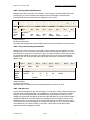
Analyzing Trionic 7 with T7Suite
Trionic 7
© Dilemma 2010
rev 1.07
Analyzing Trionic 7 with T7Suite
Preface
This document is intended for Saab fanatics and engineers who want to start understanding the Saab
Trionic 7 motor management system. It will give as much information as possible about the technical
part of the system. The only limitation will be the knowledge of the author.
In short the content of this document will enable you to understand Trionic 7 better and give you
hands-on information about altering the maps it uses. Prerequisites are minor electronics and
computer knowledge and of course some understanding of how a turbo charged engine works.
Throughout the document the T7Suite software will be referenced. This software will enable you to
really “get into” the Trionic. The T7Suite software can be downloaded from the T7Suite website.
http://trionic.mobixs.eu
Acknowledgements
The author would like to thank everyone on ecuproject for their help on getting all this information
together. Special thanks go out to General Failure, J.K. Nilsson, Hook, Hma, Vigge, Mackan, Sandy
Rus, JKB, L4staero and Steve Hayes.
These icons are used throughout the document to denote:
References
Advanced technical topics
© Dilemma 2010
rev 1.06
ii
Analyzing Trionic 7 with T7Suite
Table of contents
Preface ................................................................................................................................................. ii
Table of contents .................................................................................................................................. iii
Hardware
......................................................................................................................................... 1
Integrated circuit list .......................................................................................................................... 1
Block schematic diagram ..................................................................................................................... 2
PCB details ....................................................................................................................................... 3
Power supply ................................................................................................................................ 3
DI cartridge triggering .................................................................................................................... 4
BPC drivers (MTP3055V) ................................................................................................................. 5
Injector drivers (MTD3055VL).......................................................................................................... 5
Crankshaft position sensor (LM1815) ................................................................................................ 5
Flash .................................................................................................................................................... 6
Downloading with PEMicro USB BDM interface ....................................................................................... 7
Checksum
.................................................................................................................................. 8
Preface ........................................................................................................................................ 8
Checksum lexicon .......................................................................................................................... 8
F2 and FB checksums ..................................................................................................................... 8
Misc checksum .............................................................................................................................. 8
Area 70000 checksum .................................................................................................................... 8
How to calculate a checksum........................................................................................................... 9
Misc checksum .............................................................................................................................. 9
Area 70000 checksum .................................................................................................................... 9
Firmware
....................................................................................................................................... 10
General .......................................................................................................................................... 10
Memory map
............................................................................................................................. 10
Disassembling the code
............................................................................................................... 10
Symbol tables
................................................................................................................................ 11
General .......................................................................................................................................... 11
Maps .................................................................................................................................................. 13
General .......................................................................................................................................... 13
Fuel ............................................................................................................................................... 14
Ignition .......................................................................................................................................... 19
Ignition cassette .......................................................................................................................... 20
Torque ........................................................................................................................................... 22
Second lambda sensor ...................................................................................................................... 25
Calibration of OBD2 and LEV EVAP systems ......................................................................................... 26
Footer information
...................................................................................................................... 27
Tuning the T7...................................................................................................................................... 28
Tuning with T7Suite ......................................................................................................................... 28
Automatic transmission specifics ........................................................................................................ 44
Using the tuning wizard .................................................................................................................... 46
Stuff for SID information display ........................................................................................................ 47
CAN Bus interface ................................................................................................................................ 49
General information ......................................................................................................................... 49
Connecting to CAN bus with ECU on your desk ..................................................................................... 49
OBDII socket pin out ........................................................................................................................ 50
Real-time symbols in Trionic 7 ........................................................................................................... 51
SAAB I-bus communication ............................................................................................................... 55
SAAB P-bus communication ............................................................................................................... 72
Common mistakes and FAQ ................................................................................................................... 78
General .......................................................................................................................................... 78
Tools.................................................................................................................................................. 79
T7Suite .......................................................................................................................................... 79
BD32 ............................................................................................................................................. 80
IDA Pro
..................................................................................................................................... 80
Hex editor
References
© Dilemma 2010
................................................................................................................................ 80
.................................................................................................................................... 81
rev 1.06
iii
Analyzing Trionic 7 with T7Suite
Web references ............................................................................................................................... 81
Appendix I : Symbol list ........................................................................................................................ 82
Appendix II : Trionic 7 pinout ................................................................................................................ 85
70 pin connector .............................................................................................................................. 85
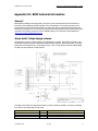
Appendix III : BDM technical information................................................................................................. 89
General .......................................................................................................................................... 89
Home build 2 chips design schema ..................................................................................................... 89
Pin out ........................................................................................................................................... 90
Appendix IV : Turbo compressor maps .................................................................................................... 91
How to read compressor maps........................................................................................................... 92
Choke area ................................................................................................................................. 92
Understanding information within the compressor map ..................................................................... 93
Surge Limit ................................................................................................................................. 94
Selecting a different turbo charger ..................................................................................................... 94
Calculating your engine’s flow requirements .................................................................................... 94
Determining the Best Wheel Trim-Housing A/R Combination .............................................................. 96
Garrett T25 specifications.................................................................................................................. 97
Mitisubishi TD04-15G specifications .................................................................................................... 98
Mitsubishi TD04-19T specifications ..................................................................................................... 99
Garrett GT28RS (GT2860R) specifications .......................................................................................... 100
Garrett GT30R specifications............................................................................................................ 101
Conclusion .................................................................................................................................... 102
Appendix V: Upgrade stages 1-7 .......................................................................................................... 103
Stage I ......................................................................................................................................... 103
Stage II........................................................................................................................................ 103
Stage III....................................................................................................................................... 104
Stage IV ....................................................................................................................................... 104
Stage V ........................................................................................................................................ 105
Stage VI ....................................................................................................................................... 105
Stage VII ...................................................................................................................................... 106
Appendix VI: Check Engine Light (CEL) ................................................................................................. 107
Appendix VII: Knock and misfire detection ............................................................................................. 108
Ionization current generation........................................................................................................... 108
Ionization current sensing ............................................................................................................... 109
Detection.................................................................................................................................. 110
Ionization Current Terminology .................................................................................................... 110
Spark Advance and Cylinder Pressure ............................................................................................... 111
Peak Pressure Concept ................................................................................................................... 112
Engine-tuning for efficiency ............................................................................................................. 113
Appendix VIII: Sensors and actuators ................................................................................................... 114
General ........................................................................................................................................ 114
Sensors ........................................................................................................................................ 114
Actuators ...................................................................................................................................... 114
Appendix X: How to connect the PD BDM programmer to a T5/T7 ECU ...................................................... 115
Pin out ......................................................................................................................................... 115
Appendix XVI: Intercooler calculation .................................................................................................... 117
Description ................................................................................................................................... 117
Equation 1 ................................................................................................................................ 117
Equation 2 ................................................................................................................................ 118
Pressure drop................................................................................................................................ 120
Appendix XVII: Acronyms .................................................................................................................... 122
Engine management specifics .......................................................................................................... 122
© Dilemma 2010
rev 1.06
iv
Hardware : Integrated circuit list
Analyzing Trionic 7 with T7Suite
Hardware
The T7 is build around a Motorola MC68332 (CPU32) microcontroller. This is a 32 bit controller that
handles the entire motor management including fuel injection, ignition timing and boost pressure
control.
The processor has a vast 4Mb (512 Kbyte) flash memory to its disposition for fetching program code
and maps. This flash memory consist of a AM29F400BT-90SI (AMD) holds the program memory.
There is a coprocessor from Philips, a P83C592FHA/019. This is a 8-bit 8051-based microcontroller
with a CAN (Controller Area Network) module. As the CAN physical line driver there is an Intel
AN82527 (same family as used in Trionic 5). RAM memory is done by two 32 Kbit SRAM chips
(U62H256S1K). There is also a special component that would appear to be a barometric pressure
sensor.
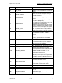
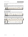
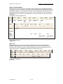
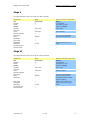
Integrated circuit list
The table below lists almost all IC’s on the board. This is just to give you an idea on what to expect.
Partnumber
TC55257DFI-85L
16233970
PC83C592
AM29F400
51862
AN82527
16238669 0H11
© Dilemma 2010
Function
SRAM (working memory)
Microcontroller
Microcontroller with CAN contr.
Flash memory
DA converter
CAN controller
Pressure sensor?
Usage
Main 32-bit CPU
8-bit coprocessor
4 Mbit
CAN line driver
rev 1.06
# on board
1
1
1
1
1
1
1
1
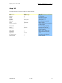
Hardware : Block schematic diagram
Analyzing Trionic 7 with T7Suite
Block schematic diagram
© Dilemma 2010
rev 1.06
2
Hardware : Block schematic diagram
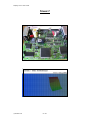
Analyzing Trionic 7 with T7Suite
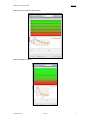
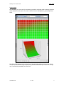
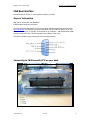
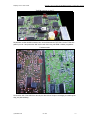
PCB details
The PCB layout is not entirely known of course because SAAB did not release details about this, even
in the service manuals. Finding out how things are setup is not so very difficult though, once you
know what the system should do and what hardware components are on the board.
The image will give you some idea on what is what on the board.
Power supply
© Dilemma 2010
rev 1.06
3
Hardware : Block schematic diagram
Analyzing Trionic 7 with T7Suite
DI cartridge triggering
The DI cartridge has a trigger input for firing the four individual sparkplugs. These are triggered by
signals from the ECU on pin 9, 10, 11 and 12 which are generated in the power driver IC CA3236 on
the Trionic PCB (topside, 16 pin DIL housing). Internally these four pins are connected as show in the
table and the image below.
DI cartridge pin
2
3
4
5
© Dilemma 2010
ECU pinnumber
7
8
67
68
CA3236 pinnumber
1 (OUT A)
3 (OUT B)
6 (OUT C)
8 (OUT D)
rev 1.06
Description
Trigger cylinder
Trigger cylinder
Trigger cylinder
Trigger cylinder
1
2
3
4
4
Hardware : Block schematic diagram
Analyzing Trionic 7 with T7Suite
BPC drivers (MTP3055V)
Injector drivers (MTD3055VL)
Crankshaft position sensor (LM1815)
© Dilemma 2010
rev 1.06
5
Hardware : Block schematic diagram
Analyzing Trionic 7 with T7Suite
Flash
© Dilemma 2010
rev 1.06
6
Hardware : Downloading with PEMicro USB BDM interface
Analyzing Trionic 7 with T7Suite
Downloading with PEMicro USB BDM interface
© Dilemma 2010
rev 1.06
7
Hardware : Checksum
Analyzing Trionic 7 with T7Suite
Checksum
Preface
The Trionic 7 ECU binary images uses several checksums to verify integrity. Most of them have been
easy to figure out, but one of them is so complicated, that it seems to been done to deter map
changing. There is still some unknowns, that would be nice to figure out. For example some binaries
don't seem to have all four checksums I've discovered. And of course there could be more checksums
that have gone unnoticed. Two of the checksums are in the end of the binary and the two other ones
are scattered in the code. The latter ones can be found be using pattern searching. Again the
calculations are pretty simple, and even the harder checksum is easy to implement. Big thanks to
solving these things goes to Tomi and General Failure.
Checksum lexicon
First of all, there are four different checksums. They have been given names by Tomi: FB checksum,
F2 checksum, Misc checksum and Area 70000 checksum.
F2 and FB checksums
The first two checksums, FB and F2, can be found at the end of the binary. This end area has been
called the file header (footer would be more logical). See also chapter Trionic 7 file header. The F2
checksum is not present in all binaries, so be aware of this. Finding the two other checksums is more
of a challenge.
Misc checksum
The Misc checksum resides inline with the code. It is usually found in the area of 0x02000...0x05000.
The checksum address can be found by pattern searching the bin file using a set of hex values along
with mask bits. If a mask bit is not set, the corresponding hex value does not have to match. Here is
the hex values, and the masks.
Pattern
0x48,0xE7,0x00,0x3C,0x24,0x7C,0x00,0xF0,0x00,0x00,0x26,0x7C,0x00,0x00,0x00,0x00,0x28,0x7C,0x00,0xF0,0x00,0x00,0x2A,0x7C
Mask
1, 1, 0, 0, 0, 0, 1, 1, 1, 1, 0, 0, 0, 0, 1, 1, 1, 1, 0, 0, 0, 0, 1, 1
So, we are searching the binary for a string of bytes beginning with 0x48, 0xE7, 0x00, 0x3C... Then
we mask out the bytes that change from binary to binary. When we’ve located this pattern, we know
where to start. Now we start primitively disassembling the code. we search for byte patterns
[0x48,0x6D], [0x48,0x78], [0x48,0x79], [0x2A,0x7C] and [0xB0,0xB9]. The three first patterns reveal
addresses and lengths of checksum areas. There are 15 checksums areas from which the Misc
checksum is calculated. The [0x2A,0x7C] pattern gives a base address for the [0x48,0x6D] addresses.
Bare with me. These [0x2A,0x7C] addresses are summed with the base address to make the actual
address. This way the address is only 2 bytes long. On the [0x48,0x79] addresses it's 4 bytes long
without any base address. And the [0x48,0x78] pattern gives 2 bytes which correspond with the
length of the checksum area. Finally the [0xB0,0xB9] pattern is followed by 4 bytes to the address of
the Misc checksum.
Area 70000 checksum
This checksum refers to an area in the region of 0x70000. Like the Misc checksum, there is no clean
way of finding out the length of the area along with the checksum address. Using pattern searching
with this also has results. There are binaries that are incompatible with this approach, so this requires
some fixing in the future.
Pattern
0x20,0x3c,0x00,0x00,0x11,0x52,0x2F,0x00,0x20,0x3C,0x00,0x00,0x09,0xD0,0x2F,0x00,0x20,0x3C,0x00,0x00,0x00,0xCC,0xD0,0x9F
Mask
1, 1, 0, 0, 0, 0, 1, 1, 1, 1, 0, 0, 0, 0, 1, 1, 1, 1, 0, 0, 0, 0, 1, 1
© Dilemma 2010
rev 1.06
8
Hardware : Checksum
Analyzing Trionic 7 with T7Suite
After finding that pattern, the masked addresses are summed together. In the pattern, the original
addresses are 0x00001152, 0x000009D0 and 0x000000CC. Summing these gives the Area 70000
length of 0x1BEE. At the same time this is the address where to find the Area 70000 checksum.
How to calculate a checksum
The FB checksum shares the same calculation method as Misc and Area 70000 checksums. It's simply
a sum of the bytes from the checksum area. Four bytes are made into a 32 bit value and summed
with the next 32-bit value. This goes on until there are fewer than 4 bytes left. The last 1...3 bytes are
then individually summed together with the checksum.
Misc checksum
The Misc checksum is a sum of the individual checksums calculated from 15 areas. The used
checksum calculation the same as with the FB checksum.
Area 70000 checksum
Once you have found the length of the Area 70000, you can calculate the checksum by using the
function described in section “FB checksum”. The start address is 0x70000. Notice that your binary
might not have this area present.
© Dilemma 2010
rev 1.06
9
Firmware : General
Analyzing Trionic 7 with T7Suite
Firmware
General
Once you are done with dumping the flash contents and you want to do more than only alter variables
and maps you can start analyzing the binary. This is a difficult task because there are a lot of different
firmware versions, stock ones – maybe different per MY and tuned ones that differ for every
manufacturer and stage. In every case the code can be disassembled using a 6833x disassembler like
the one in IDAPro. There are scripts available to automatically disassemble the code and make it more
readable by replacing addresses by variable names that are extracted from the symboltable inside the
binary.
Memory map
Disassembling the code
© Dilemma 2010
rev 1.06
10
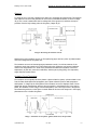
Symbol tables : General
Analyzing Trionic 7 with T7Suite
Symbol tables
General
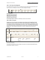
Each T7 firmware file contains a symbol table describing data structures in the program. The major
problem is that from some point in time SAAB started to compress the symbol tables in the binary file.
Probably just to save space in the flash memory but it has made tuning a little harder. We actually
need these symbol names because they tell us what a certain memory location means. For unpacked
binaries these symbols can be extracted together with their corresponding memory addresses (ROM
and RAM).
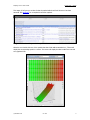
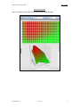
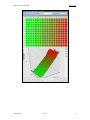
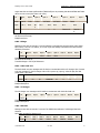
Image 4 gives a general idea on what these symbol tables look like.
Image 1: Symbol table in T7 firmware
While examining the symbol table you can see that the separator is 0x00. In contrast to T5 where
symbol and SRAM addresses reside in the same table, we now only find the symbol name. In another
table in the binary we can find flash addresses and lengths in the same sequence as the symboltable.
Finding start of symbol table:
Search binary for string the first sequence of 15 zeros.
Finding start of address lookup table:
Search binary for 20 00 00 00 XX YY 00 F0 where XX YY is the index of the first symbol found in the
symbollist.
To save you the time to lookup all addresses manually the T7Suite application will extract all symbol
information in one run. Symbol name, flash address and length will be displayed all together.
© Dilemma 2010
rev 1.06
11
Symbol tables : General
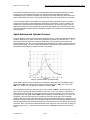
Analyzing Trionic 7 with T7Suite
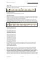
This image (6) will give you an idea of what the symbol table should look like once it has been
extracted. See appendix I for a complete list of known symbols.
Image 2: Screenshot of a part of the symbol table
When the user double clicks one of the symbols that has a flash address attached to it, T7Suite will
display the corresponding symbol in a viewer. This viewer will display the data in table form was well
as in graphical form.
© Dilemma 2010
rev 1.06
12
Maps : General
Analyzing Trionic 7 with T7Suite
Maps
General
A lot of maps in the T7 are not only made up of a piece of raw data. It also includes x-axis and y-axis
information. T7Suite will automatically display all known axis information when a map is opened. IN
Trionic 7 most symbol have an English name (Trionic 5 has lots of Swedish names) that explains lots
about its function. Also, the symbols are categorized by name, which makes browsing the symbols
much easier. All torque calibration symbols start with “TorqueCal.”. T7Suite groups all symbols by
their respective category by default.
© Dilemma 2010
rev 1.06
13
Maps : Fuel
Analyzing Trionic 7 with T7Suite
Fuel
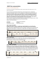
Fuel calculation in Trionic 7 is based on the Airmass entering the engine. In rough steps this seems to
be the calculation’s flow:
Description
Explaination
1
Basic calculation of fuel quantity per combustion
2
Compensation
3
Closed loop
4
Correction for purge
5
Multiplicative adaptation (long term fuel trim)
6
Additive adaptation
7
Starting fuel quantity
8
Fuel quantity per combustion to be injected
9
Injector opening duration
10
Injection twice per combustion
11
Voltage dependant needle lift duration added
(battery correction)
Fuel cut
Activation of injector
The current air mass/combustion is divided by 14.7
and sent to box 2. The unit is now in mg
fuel/combustion
In case of a cold engine, shortly after starting, rapid
load changes, knocking or high loads, the current
value is multiplied by a compensation factor
The closed loop value is used as a multiplier. The
value is then sent to box 4
Multiply by the value for purge adaptation. The
value is sent to box 5
The multiplicative adaptation value is used as a
multiplier and the new value is sent to box 6
The additive adaptation value is added and the new
value is sent to box 7
If the engine has not yet started, starting fuel is
selected. The value is sent to box 8
The fuel quantity per combustion is the amount of
petrol to be supplied to the engine. The value is sent
to box 9
Converts the value to the time during which the
injector must be open and the new value is sent to
box 10
Injection takes place twice per combustion until the
camshaft position has been found. Injection duration
is divided by two. The value is sent to box 11
Adds the injector time delay, which is voltage
dependant. The value is sent to box 12
The value is sent to box 13 unless fuel cut is active
At a DETERMINED crank shaft angle, the
microprocessor will control the transistor for the
injector that is next in the firing order
12
13
The basic fuel quantity is calculated based on Airmass and Injector constant. This injector constant is
called InjCorrCal.InjectorConstant.
© Dilemma 2010
rev 1.06
14
Maps : Fuel
Analyzing Trionic 7 with T7Suite
If the engine is not warmed up yet, an alternate fuel map is used called BFuelCal.StartMap. If the
engine has reached operating temperature the normal map “BfuelCal.Map” is used.
You will see the areas calibrated to be run in closed loop have a value of around 1.00. It can be sort
of .98-1.02 or so. Then you will notice the high load part of the maps ramp up to enrich the mixture.
The trick is to set the closed loop part of the map first, the areas that are represented by values of
1.00.
You will need to switch closed loop off and drive around with a wideband in the tailpipe.
What you want to achieve is an AFR of 14.7 for petrol while driving around under light loads where
the value is 1.00. What this does is T7 calculates the injection time to be say 5ms, if that is not
correct it is multiplied by this map. Say you need to enter a value of 1.1 in the map to get correct AFR
it will change injection time to 5.5ms (5ms*1.1=5.5ms)
The idea is to get closed loop area correct first to stop any negative adaption once the tune is finished
and allowed to run in closed loop again. If your closed loop areas of your fuel map is too rich it will
negatively adapt over a long period of time. This will can have the effect of leaning your AFR's across
the board.
Example: you make a tune, closed loop AFR's are fine (because the O2 is making it fine through
feedback) but unknown to you its rich and short term fuel trim is driving negatively 13%. I.e. is
leaning off injection time by 13%.
You don’t notice this and make some full power runs to check AFR its fine at say 12.5 AFR.
After several weeks the multiplicative adaptation (Long term fuel trim) has absorbed some adaption
and has earned a value of -13% this will now subtract 13% from whole fuel calculation including full
power. All of a sudden your full power AFR has jumped up to 14.0 AFR, engine failure happens very
easily from here.
Now back to fuel mapping. To set closed loop area of fuel map monitor the AFR in this light load area
if its wrong after adjusting for large injectors start by just adjusting the Injector constant up and down
accordingly instead of altering the closed loop area of the BfuelCalMap. This will affect the whole map
© Dilemma 2010
rev 1.06
15
Maps : Fuel
Analyzing Trionic 7 with T7Suite
instead of one point. By doing it this way you can almost get AFR spot on in closed loop area just by a
few goes at adjusting the injector constant.
It can be found in InjCorrCal.InjectorConst, the value represents the injectors flow in mg of fuel (not
capacity or cc's as injectors are normally rated in). The injector constant is a calculation factor used by
T7 to calculate injection time.
Once closed loop area is done the high load area can be mapped. If its too lean just increase the
values in the relative column relating to what site of the map you are running in. Once your high load
areas are done, activate closed loop again so you can see how it all runs. Monitor fuel adaptations and
AFR etc.
One thing to note is how quickly it drops into open loop under full throttle.
By going into open loop the o2 sensor is "masked" where the ECU listens to what its saying but
ignores it, this allows afr's to go beyond 14.7 and injection correction is directly taken from the fuel
map we just adjusted allowing much enrichment to cool charge etc.
To alter open loop enrichment you can change at what Airmass point does it change to open loop.
This map is called LambdaCal.MaxLoadNormTab. Also, open loop entry (so, leaving closed loop
situation) has a delay attached to it. This way, short overruns of the maximum load will not
immediately result in leaving closed loop. Stock bins often have this set to 2000 milliseconds which
seems quite long. If you want to ECU to leave closed loop faster after overrunning the load limit, just
decrease the time in LambdaCal.TimeOpenLoop.
© Dilemma 2010
rev 1.06
16
Maps : Fuel
Analyzing Trionic 7 with T7Suite
Battery correction values for injector latency
Water temperature correction
© Dilemma 2010
rev 1.06
17
Analyzing Trionic 7 with T7Suite
Maps :
Fuel injection correction map for knock conditions
© Dilemma 2010
rev 1.06
18
Maps : Ignition
Analyzing Trionic 7 with T7Suite
Ignition
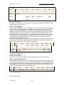
Description
Explanation
1
Idling speed ignition timing
2
Normal ignition timing
3
Selection of ignition timing
4
Catalytic converter heating timing
5
Engagement of catalytic converter heating timing
6
7
Total
Compensation
8
Knock control
9
Total
10
Selection of ignition timing
11
Starting ignition timing
12
Activate relevant trigger
With idle speed control active, the timing is adjusted
to stabilize idle engine speed. The value is sent to
box 3
When idle speed control is inactive, the ignition
timing is read from a load and engine speed
depending matrix. The value from the matrix is
optimized for lowest fuel consumption (best engine
torque) and sent to box 3
One of the ignition timing calculation is selected
depending on which function is active. The value is
sent to box 6
In order to heat up the catalytic converter as fast as
possible after start, the ignition will be retarded.
This is a compensation matrix that is added to the
value in box 3. The matrix is dependent on load and
engine speed
The function is active when coolant temperature is
above -10 degrees Celsius and below +64 degrees
Celsius
The value from box 5 is added to the value of box 3
The ignition timing is corrected depending on engine
coolant temperature and intake air temperature. The
value is sent to box 6.
If knocking occurs, a timing retardation will be
calculated. The value is sent to box 6
The compensation angle and knock retardation are
totalled to give the current ignition timing. The value
is sent to box 7
Starting ignition timing is selected when the engine
has not been started. The value is sent to box 9
Starting ignition timing is selected when the engine
has not yet been started. The value is sent to box 9
At the calculated crankshaft angle, the
microprocessor controls the transistor for the trigger
that is next in firing order
© Dilemma 2010
rev 1.06
19
Maps : Ignition
Analyzing Trionic 7 with T7Suite
Ignition cassette
The ignition cassette is mounted on the valve cover on top of the spark plugs. The ignition cassette
houses four ignition coils/transformers whose secondary coil is direct connected to the spark plugs.
The ignition cassette is electrically supplied with battery voltage from the main relay (B+) and is
grounded in an earth point. When the main relay is activated the battery voltage is transformed to
400 V DC which is stored in a capacitor. The 400 V voltage is connected to one of the poles of the
primary coil in the four spark coils. To the ignition cassette there are four triggering lines connected
from the Trionic ECU, pin 9 (cyl. 1), pin 10 (cyl. 2), pin 11 (cyl. 3) and pin 12 (cyl. 4). When the ECU
is grounding pin 9, the primary coil for the first cylinder is grounded (via the ignition cassettes B+
intake) and 400 V is transformed up to a maximum of 40 kV in the secondary coil for cyl. 1. The same
procedure is used for controlling the ignition on the rest of the cylinders.
Idle control
© Dilemma 2010
rev 1.06
20
Maps : Ignition
Analyzing Trionic 7 with T7Suite
Normal mode ignition
Ignition is normally controlled by the main ignition matrix: IgnNormCal.Map
© Dilemma 2010
rev 1.06
21
Maps : Torque
Analyzing Trionic 7 with T7Suite
Torque
Trionic 7 is a torque/Airmass request system instead of a boost request system like Trionic 5 is.
The basic procedure for the Airmass controller is like in the table below.
Description
Explaination
1
Driver request
2
Cruise control request
3
Select highest value
4
Engine torque limitation
5
6
Select lowest value
Compensation request
7
Other air request
8
9
10
11
Totalling values
Total requested mg/c
Total Airmass request
Throttle control
The control module reads pedal potentiometer 1 and converts the
voltage to Airmass per combustion (mg/c). The value is sent to box 3
When cruise control is active, the air mass per combustion required to
maintain the set speed is calculated. The value is sent to box 3
The control module selects the highest of the two values (box 1 or box
2). The value is sent to box 5
The maximum permissible air mass per combustion varies depending
on the engine type. During operation, the maximum permissible mg/c
must also be limited to protect the engine, gearbox, brakes and turbo
The control module selects the lowest value and sends it to box 8
When the AC compressor is on, and when the heated rear window or
radiator fan is on, the mg/c required to compensate for the increased
load is calculated. The value is sent to box 8
The control module calculates the mg/c required for idle speed control.
The value is sent to box 8
The control module totals all the values. The total is sent to box 9
12
Current mg/c
13
Turbo control
14
Current mg/c
© Dilemma 2010
The requested mg/c is converted to requested voltage for throttle
position sensor 1. The charge air pressure and intake air temp are
used to correct this conversion. The throttle motor rotates the throttle
until the current voltage for throttle position sensor 1 corresponds with
the requested voltage
The requested mg/c is also compared with the current mg/c (MAF
reading). If needed the requested voltage for throttle position sensor 1
is finely adjusted
If mg/c is too high for throttle alone the turbo control will take over.
The excess is converted to a PWM which controls the charge air
control valve. The absolute pressure sensor is used to correct the
conversion
The requested mg/c is compared to current mg/c and the charge air
control vale PWM is finely adjusted if required
rev 1.06
22
Maps : Torque
Analyzing Trionic 7 with T7Suite
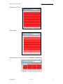
Torque request
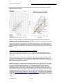
So, if the driver (or cruise control for that matter) pressed the accelerator pedal he actually requests a
certain Airmass from the system. This value is fetched from the PedelMapCal.m_RequestMap shown
below.
The table holds Airmass values for each position of the accelerator pedal and each rpm site. Trionic
now looks up the estimated engine output (torque) based on Airmass and rpm. This is done through
map “TorqueCal.M_NominalMap” as shown next.
© Dilemma 2010
rev 1.06
23
Maps : Torque
Analyzing Trionic 7 with T7Suite
© Dilemma 2010
rev 1.06
24
Maps : Second lambda sensor
Analyzing Trionic 7 with T7Suite
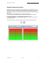
Second lambda sensor
In the years Trionic 7 was shipped on cars, several things changed in these cars setups. One of the
major changes was the introduction of the second lambda (oxygen, O2) sensor that is placed after the
catalyst to ensure the catalyst is working properly. If you want to run software from a double lambda
sensor car in a single lambda car, you have to make some changes in the settings. This information is
courtesy of L4staero.
Turning off second lambda sensor
You can use this procedure in cars having only one lambda sensor and in cars having two lambda
sensors, but with a missing catalyst.
Map
LambdaCal.ST_AdapEnable
Value
0
Description
Second lambda sensor disabled
LambdaCal.ST_AdapEnable
1
Second lambda sensor enabled
Alternative solution to turning off second lambda
Change low limit on O2heaterPostCal.I_LowLim to 0 mA to disable sensor heater error, and change
CatDiagCal.LoadHi and LoadLo to values never seen normally, like 30 and 20.
Map
O2HeatPostCal.I_LowLim
CatDiagCal.LoadLo
CatDiagCal.LoadHi
Value
0
20
30
Description
Second lambda sensor disabled
Second lambda sensor disabled
Second lambda sensor disabled
O2HeatPostCal.I_LowLim
CatDiagCal.LoadLo
CatDiagCal.LoadHi
230
140
425
Second lambda sensor enabled
Second lambda sensor enabled
Second lambda sensor enabled
© Dilemma 2010
rev 1.06
25
Maps : Calibration of OBD2 and LEV EVAP systems
Analyzing Trionic 7 with T7Suite
Calibration of OBD2 and LEV EVAP systems
If we want to run a file that was developed for OBD2 or a LEV car in an earlier car we run into
problems because the early car is missing a second catalyst, a tank pressure sensor and a purge
canister behind the fuel tank. If you have an early B205E/L engine you simply couldn’t run a later
B205R software version in it because it would through CEL’s for the missing hardware. We need to
make changes to the file before we can run in on an earlier car (e.g. switch of the control of the new
hardware).
OBDCal.OBD2Enabled= This is self explanatory, if car is OBD2 put value at 1 if it's not OBD2 put value
at 0.
On this point in later bins(compressed) there is EOBDEnable which is always on in EC2000 EU files
and LOBDEnable which is always on in EC2000 RW files. File type is shown in firmware information
under engine type.
OBDCal.EnableOBD2Limit= As above but its a 4 byte value. If done in Hex value for a OBD2 car is
00000001 and for non-OBD2 car is 00000000. As shown in T7suite is 2 values. OBD2 cars top value is
1 and bottom value is 0. In non OBD2 car both values are 0.
OBDCal.evapEquipmentExist= If car is equipped with a canister at rear of tank and a tank pressure
sensor value will be 1. If neither exist value should be set to 0.
Info on LEV (Low Emission Vehicle)
For example take a 2001 9-3 Aero (or SE as called in USA) equipped with a B205R, Saab's decision to
take all "R" engines and clean them so to speak by developing new emission systems for them leaves
them with some differences to their low level engine relatives. The term LEV(Low emission vehicle) in
this sense refers to Saab's decision to add a second catalytic converter and a tank pressure sensor
and a large purge canister behind fuel tank, as well as adding a 2nd oxy to monitor condition of first
cat.
© Dilemma 2010
rev 1.06
26
Maps : Calibration of OBD2 and LEV EVAP systems
Analyzing Trionic 7 with T7Suite
Footer information
If we look at the footer in the binary (last page in hex viewer) we see a set of reversed strings. Each
of these strings contains an identifier. These identifiers have a hardcoded meaning.
Identifier
0x91
0x94
0x95
0x97
0x9A
0x9C
0x9B
0xF2
0xFB
0xFC
0xFD
0xFE
0xFA
0x92
0x93
0xF8
0xF7
0xF6
0xF5
0x90
0x99
0x98
0xF9
© Dilemma 2010
Length
0x09
0x07
0x0C
0x1E
0x04
0x04
0x04
0x04
0x04
0x04
0x04
0x04
0x05
0x0F
0x07
0x02
0x02
0x02
0x02
0x11
0x06
0x0D
0x01
Description
Ecuid.vehicleidnr
Ecuid.ecuhardwversnr
Ecuid.ecusoftwnr
Ecuid.ecusoftwversnr
Ecuid.softwaredate
variable name table crc (not really sure)
Symboltable (packed table with symbol names)
F2 checksum
Romchecksum.piareachecksum
Romchecksum.BottomOffFlash
RomChecksumType
Romchecksum.TopOffFlash
Lastmodifiedby
Ecuid.partnralphacode (IMMO)
Ecuid.ecuhardwnr
?
?
?
?
Ecuid.scaletable (VIN)
Ecuid.testerserialnr
Ecuid.enginetype
Romchecksum.Error
rev 1.06
27
Tuning the T7 : Tuning with T7Suite
Analyzing Trionic 7 with T7Suite
Tuning the T7
Tuning with T7Suite
To get the ECU to produce more engine output, several parameters (maps) have to altered. This
chapter will give you a general idea on what to change – and why – for getting to an approximate
stage II equivalent. The example is a 9-3 B205R.
AirCtrlCal.m_MaxAirTab
Airmass value from controller where area map has reached max-area and there is no point to increase
the I-part. Resolution is 1 mg/c
.
AirCtrlCal.m_MaxAirE85Ta ( if running on E85 )
Same as above for E85
BoostCal.I_LimTab
Load limit tab. to enable the I Part of boost regulator. If the load request from Airmass master is
above this value plus the hysteresis is the I Part enabled and the throttle closed loop is disabled. If
the load request from Airmass master is below this value is the I Part disabled and the throttle is
allowed to run in closed loop.
© Dilemma 2010
rev 1.06
28
Tuning the T7 : Tuning with T7Suite
Analyzing Trionic 7 with T7Suite
BoostCal.P_LimTab
Load limit tab. to enable the P Part of boost regulator. If the load request from Airmass master is
above this value plus the hysteresis is the P Part enabled. If the load request from Airmass master is
below this value is the P Part disabled.
BoostCal.RegMap
Main constant matrix. Resolution is 0.1 %.
BstKnkCal.MaxAirmass (divide by 3,1 for approx torque, ignition, airtemp etc affect this!)
Map for max allowed Airmass for manual gearbox, m_nHigh. Resolution is 1 mg/c.
© Dilemma 2010
rev 1.06
29
Tuning the T7 : Tuning with T7Suite
Analyzing Trionic 7 with T7Suite
BstKnkCal.MaxAirmassAu
Map for max allowed Airmass for automatic gearbox, m_nHigh. Resolution is 1 mg/c.
FCutCal.m_AirInletLimit
If the "MAF.m_AirInletFuel" is higher than this limit during m_AirInletTime will the fuelcut be activated
( pressure guard ).
© Dilemma 2010
rev 1.06
30
Tuning the T7 : Tuning with T7Suite
Analyzing Trionic 7 with T7Suite
IgnE85Cal.fi_AbsMap ( if you want to change the ignition )
Ignition map for E85 fuel. Resolution is 0.1 °.
IgnNormCal.Map ( if you want to change the ignition )
Normal ignition map. Resolution is 0.1 °.
MapChkCal.CheckSum (automatically updated in between every map change with T7suite!)
MaxVehicCal.v_MaxSpeed( max speed )
© Dilemma 2010
rev 1.06
31
Tuning the T7 : Tuning with T7Suite
Analyzing Trionic 7 with T7Suite
PedalMapCal.m_RequestMap
Requested Airmass from the driver as a function of rpm and accelerator pedal position. Resolution is 1
mg/c.
TorqueCal.M_ManGearLim
Maximum engine torque limit for each gear in the manual gearbox. Resolution is 1 Nm.
© Dilemma 2010
rev 1.06
32
Tuning the T7 : Tuning with T7Suite
Analyzing Trionic 7 with T7Suite
TorqueCal.m_AirTorqMap (This is where all torque limiters take their data from and therefore
needs to be "fooled" if you are running 400nm+ or an automatic!)
Data-matrix for nominal Airmass. Engine speed and torque are used as support points. The value in
the matrix + friction Airmass (idle Airmass) will create the pointed torque at the pointed engine speed.
Resolution is 1 mg/c.
axis to the above map: TorqueCal.m_AirXSP
© Dilemma 2010
rev 1.06
33
Tuning the T7 : Tuning with T7Suite
Analyzing Trionic 7 with T7Suite
TorqueCal.M_EngMaxTab
Data-table for maximum engine out put torque for manual cars. Resolution is 1 Nm.
TorqueCal.M_EngMaxAutTab
Data-table for maximum engine output torque for automatic cars. Resolution is 1 Nm.
TorqueCal.M_5GearLimTab
Data-table for maximum engine output torque for manual cars on fifth gear. Resolution is 1 Nm.
© Dilemma 2010
rev 1.06
34
Tuning the T7 : Tuning with T7Suite
Analyzing Trionic 7 with T7Suite
TorqueCal.M_EngMaxE85Tab ( if running on E85 )
Data-table for maximum engine output torque when running on E85. Resolution is 1 Nm.
TorqueCal.m_PedYSP
Air mass support points for (Calc) X_AccPedalMap. Resolution is 1 mg/combustion.
© Dilemma 2010
rev 1.06
35
Tuning the T7 : Tuning with T7Suite
Analyzing Trionic 7 with T7Suite
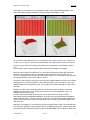
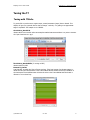
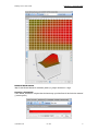
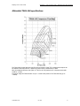
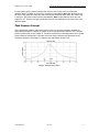
Tuning Boost calibration
This map holds percentages (0.1% accurate) of how much air should be passed to the return hose of
the boost control value. The higher the value, to more air is bled off and the less the wastegate will
open (and thus, the more air the turbo will be spooling). As you can see, the more Airmass is
requested (x – axis) the more the wastegate is held shut and thus, the more Airmass the turbo will be
providing. If we want more Airmass from the turbo, we need to keep the wastegate shut longer and
thus we have to enter higher numbers on the right side of the table.
© Dilemma 2010
rev 1.06
36
Tuning the T7 : Tuning with T7Suite
Analyzing Trionic 7 with T7Suite
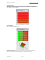
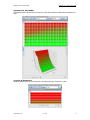
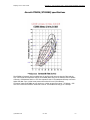
Altering Airmass limiter
To be able to flow more air though the engine that is allowed in the stock configuration we will have
to modify the Airmass limiter tables as well. Note that there are two different ones, one for manual
gearbox and one for automatic gearbox. This example will only show the manual gearbox table
(BstKnkCal.MaxAirmass) but for automatic cars BstKnkCal.MaxAirMassAu needs to be changes.
As you can see, the maximum amount of Airmass allowed is approximately 970 mg/c. We need to
change the table so that it will allow more Airmass. In this case we just up the table with 25% with
the math functions in T7Suite.
NOTE: Please do not simply turn off this limiter by setting it way higher than the actually intended
level because it is an important limiter to provide engine safety.
Altering fuelcut
Then there’s the fuelcut function to worry about. We need to increase the limit of what the fuel cut
function will accept to prevent it from shutting of fuel too early.
NOTE: Please do not simply turn off this limiter by setting it way higher as the actually intended level
because it is an important limiter to provide engine safety.
© Dilemma 2010
rev 1.06
37
Tuning the T7 : Tuning with T7Suite
Analyzing Trionic 7 with T7Suite
Engine speed limiter
To prevent the system to reduce Airmass above engine speeds that are still acceptable we need to
change MaxSpdCal.n_EngLimAir as well. Y axis values are engine temperature (coolant). Please note
that 200 rpm above this limit, the fuel cut mechanism will become active!
Vehicle speed limiter
An option is to increase the vehicle speed limiter as well. In this stock binary the vehicle speed is
limited to 240 km/h. We can change it to – for example 280 km/h.
© Dilemma 2010
rev 1.06
38
Tuning the T7 : Tuning with T7Suite
Analyzing Trionic 7 with T7Suite
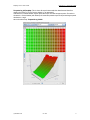
Airmass request
To get more from the engine than in the stock configuration we need to actually request more
Airmass for a certain pedal position and rpm site. This can be done through
PedalMapCal.m_RequestMap. Because we want more power at wide open throttle (from the drivers
perspective) we need to increase the Airmass request at pedal positions in the high percentage range
(top of the table).
As you can see we increased the top two rows so that a maximum of 1350 mg/c will be requested.
In addition we need to alter the y axis support point for the pedal map that lets Trionic lookup a pedal
position for a given Airmass. This map is called TorqueCal.m_PedYSP. This axis map should support
the maximum Airmass we’re requesting in the m_Requestmap, so in our case we need to modify the
map to match the 1350 mg/c we are requesting as a maximum.
© Dilemma 2010
rev 1.06
39
Tuning the T7 : Tuning with T7Suite
Analyzing Trionic 7 with T7Suite
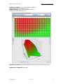
The map that uses this axis is called TorqueCal.x_AccPedalMap. It it shown below with the altered
axis values for clarification.
© Dilemma 2010
rev 1.06
40
Tuning the T7 : Tuning with T7Suite
Analyzing Trionic 7 with T7Suite
Torque limiter
To prevent to system to reduce Airmass above a certain engine output, the torque limiter needs to be
increased according to expected engine output.
Torque limiter for E85 fuel
Torque limiter for manual gearbox in higher revs
© Dilemma 2010
rev 1.06
41
Tuning the T7 : Tuning with T7Suite
Analyzing Trionic 7 with T7Suite
Torque limiter in 5th gear
Overboost table
Maximum Airmass for I-part of PID controller (AirCtrlCal.m_MaxAirTab)
© Dilemma 2010
rev 1.06
42
Tuning the T7 : Tuning with T7Suite
Analyzing Trionic 7 with T7Suite
TorqueCal.m_AirTorqMap (This is where all torque limiters take their data from and therefore
needs to be "fooled" if you are running 400nm+ or an automatic!)
Data-matrix for nominal Airmass. Engine speed and torque are used as support points. The value in
the matrix + friction Airmass (idle Airmass) will create the pointed torque at the pointed engine speed.
Resolution is 1 mg/c.
Finally, we’re all done!
© Dilemma 2010
rev 1.06
43
Tuning the T7 : Automatic transmission specifics
Analyzing Trionic 7 with T7Suite
Automatic transmission specifics
In automatic Trionic 7 cars the TCM (Traction Control Module) sends a torque limit over can to the
ECU (Trionic). This means – theoretically - you cannot achieve more torque than the torque limit the
TCM dictates. The only known way around this at present time is to make Trionic THINK it’s not
making that much torque, so we have to fool the ECU into thinking it is still below the torque limit set
by the TCM.
There are different TCM limits depending on year, engine type, gearbox etc.
A MY01-AERO AUT has a 330NM limiter while a 5 speed automatic gearbox has a 350Nm limit.
To fool the ECU into thinking it is making less torque is to rescale the x-axis for
TorqueCal.mAirTorqMap which is TorqueCal.M_EngXSP. The top value in this list must be no
more than the TCM limit.
In this case the top three rows have been altered to keep the calculated torque below 330Nm.
400 -> 330Nm
350 -> 320Nm
320 -> 310Nm
© Dilemma 2010
rev 1.06
44
Tuning the T7 : Automatic transmission specifics
Analyzing Trionic 7 with T7Suite
This means that when requesting 330Nm you will actually get 400, 320 will get you 350 and so on.
The torque limiters in TorqueCal.M_EngMaxAutTab must be scaled with this in mind...
In this case 400Nm between 2780 and 3920rpm. Values in between you need to recalculate, at
4300rpm the user wanted 390Nm, (400=330, 350=320) means that 322=360, 324=370, 326=380,
328=390nm
If you want to use the same bin in manual cars all manual limiters must be calculated and set
correctly!
NOTE: In Bio power bins TorqueCal.M_EngMaxE85Tab!
© Dilemma 2010
rev 1.06
45
Tuning the T7 : Using the tuning wizard
Analyzing Trionic 7 with T7Suite
Using the tuning wizard
T7Suite incorporates a tuning wizard. This wizard allows you to automatically alter the maps in the
binary file to get it to a stage I equivalent file. The wizard can be activated by selecting “Tuning” >
“Easy tune to stage I” from the menu. A dialog will appear in which you can confirm that you want to
tune the file to stage I. Once you’ve selected this the process will start. After a few seconds a report
will appear showing all actions taken on your file.
© Dilemma 2010
rev 1.06
46
Tuning the T7 : Stuff for SID information display
Analyzing Trionic 7 with T7Suite
Stuff for SID information display
T7Suite incorporates a function to allow visualization of information on the SID (System Information
Display). This way you can view real-time information without utilizing the Canbus interface. You can
select the variables you want the SID to display using the SID information selection option in T7Suite.
Also, the software should be opened to be able to view the selected data on the SID. This is done in
the firmware information screen.
© Dilemma 2010
rev 1.06
47
Tuning the T7 : Stuff for SID information display
Analyzing Trionic 7 with T7Suite
Some tips on how to use the SID information option:
ECMStat.ST_ActiveAirDem shows the current Airmass limiter
ECMStat.P_Engine shows calculated engine power (hp)
ECMStat.AirFuelRatio shows calculated AFR
ECMStat.p_Diff shows boost pressure (manifold – ambient) in 0.1 kPa units
BstKnkProt.MapPointer shows the offset in 0.1 degrees for BstKnk.MaxAirmass (so, the
ignition offset for knock)
ExhaustCal.ST_Enable allows you to enable and disable the EGT algorithm. These algorithms
are based on the stock engine and won’t be properly calibrated for a stage 3+ setup.
KnkDetAdap.KnkCntCyl first 2 bytes show cylinder 1 knock count, next 2 bytes shows cylinder
2 knock count etc.
© Dilemma 2010
rev 1.06
48
Tuning the T7 : General information
Analyzing Trionic 7 with T7Suite
CAN Bus interface
Interfacing with the Trionic T7 unit through the CAN bus is possible.
General information
Chip used on Trionic side: Intel AN825257
Communication speed used: 615 Kbit/s
The most frequently used interface for this is the Lawicel CANUSB interface that can be found on
www.canusb.com. This interface can convert CAN signals onto you USB port and vice versa. The
interface has a USB port on one side – that connects to you computer – and an male RS232 (DB9)
connector on the other side. This side connects to the CAN bus of the Trionic.
The Lawicel interface has the following pin out on the DB9 connector.
Connecting to CAN bus with ECU on your desk
© Dilemma 2010
rev 1.06
49
Tuning the T7 : OBDII socket pin out
Analyzing Trionic 7 with T7Suite
OBDII socket pin out
On some models, the OBDII port enables you to connect to the I bus directly. On most models, you
need to wire into the P-pus (preferably, because data transmission rates are tenfold of that on the Ibus) or into the I-bus directly. The P-bus can be found at the pins of the ECU (as described on the
previous page), the I-bus can be found in a lot of places like the CD changer connector in the trunk
(other spots are shown in the table below).
Pinnumber
1
2
3
4
5
6
7
8
9
10
11
12
14
15
16
I-Bus
P-Bus
Description
J1850 Bus+
Chassis Ground
Signal Ground
CAN High (J-2284) Note: not on all models
ISO 9141-2 K Line
J1850 BusAirbag Controller (?)
ABS Controller (?)
CAN Low (J-2284) Note: not on all models
ISO 9141-2 L Line
Battery Power
There components are hooked up to the I-Bus (instrumentation bus):
SID
Saab Information Display
ACC
Automatic Climate Control
RADIO
Radion control unit
CDC
CD-Changer – in trunk
PSM
Power Seat Memory
STC
Soft Top Control – for carbios
Twice
Theft Warning Integrated Control Electronics
DICE
Dashboard Integrated Control Electronics
These components are hooked up to the P-Bus (powertrain bus)
TC/ABS
Traction Control/ABS – in case of ABS only (without Traction Control)
it is connected to MIU
Trionic 7
Motormanagement for petrol engines
VP44-PSG16 Motormanagement for diesel engines
TCM
© Dilemma 2010
Transmission Control System – in autmatic geared cars (petrol only)
rev 1.06
50
Tuning the T7 : Real-time symbols in Trionic 7
Analyzing Trionic 7 with T7Suite
Real-time symbols in Trionic 7
This table gives a summary of interesting symbols to monitor in Trionic 7.
SID name
Symbolname
Rpm
In.n_Engine
Lamb
Lambda.LambdaInt
Igna
Out.fi_Ignition
Teng
In.T_Engine
STAd
E85Adap.ST_Adap
Tair
In.T_AirInlet
Ioff
IgnProt.fi_Offset
Meng
Out.M_Engine
Mlow
TorqueProt.M_LowLim
nErr
obdNoOfFaults
Pbef
In.p_AirBefThrottle
Pinl
In.p_AirInlet
Pair
In.p_AirAmbient
mReq
m_Request
mAIR
MAF.m_AirInlet
Miss
Missf.nrOfCountedMisfire
Pfac
BoostProt.PFac
Ifac
BoostProt.IFac
PWM
Out.PWM_BoostCntrl
tSta
ECMStat.t_StartTime
LIMP
Mode
Me85
Ad85
OBDAdap.ThrLimpHomeNr
SID.ST_Mode
In.X_EthanolSensor
E85.X_EthanolActual
© Dilemma 2010
Description
Engine speed UNIT : rpm MAX : 8000 MIN : 25
(set to 10 when engine starts to move) TRANS : V
= P. Resolution is 1. Interval is Every combustion /
5 ms when engine is still.
Global closed loop integrator. Update : every
combustion. V6: Bank 1. Resolution is 0.01 %.
Actual ignition angle. A positive value is before TDC
and a negative value is after TDC. Resolution is 0.1
°. Interval is Every combustion.
Engine coolant temperature UNIT : (C MAX : 150
MIN : -40 TRANS : V = P. Resolution is 1. Interval
is 1000 ms.
Inlet air temperature UNIT : (C MAX : 140 MIN : 40 TRANS : V = P. Resolution is 1. Interval is 1000
ms.
Shows ignition angle output from offset functions.
Resolution is 0.1 °.
Engine torque UNIT : Nm MAX : 400 MIN : -100
TRANS : V = (P+. Resolution is 1. Interval is 10ms.
By the Torque Master selected lowest torque limit
request, corrected with adaption value made at
idle.
Number of errors stored
Engine inlet air pressure UNIT : kPa MAX : 300
MIN : 0 TRANS : V = P * 10. Resolution is 0.1.
Interval is Every combustion.
Engine inlet air pressure UNIT : kPa MAX : 300
MIN : 0 TRANS : V = P * 10. Resolution is 0.1.
Interval is Every combustion.
Barometric air pressure UNIT : kPa MAX : 120
MIN : 50 TRANS : V = P * 10. Resolution is 0.1.
Interval is 250 ms.
Requested airmass
Airmass in milligram per combustion. This airmass
is the actual load value in the ECM. (Unfiltered)
Calculated from ActualIn.Q_AirInlet. Resolution is 1
mg/c. Interval is every combustion.
Counts the nr of misfire that has not been filtered
or rpm diff filtered.
Calculate P part for regulator. load diff * P const P
= 100. Update : every 10 msec. Resolution is
0.1 %.
Calculated I part for regulator. load diff * I const I
= I + 1000. Update : every 10 msec. Resolution is
0.1 %.
Duty-cycle for boost pressure valve. Resolution is
0.1 %. Interval is every 20 ms.
Engine start time, measured by measuring the time
from that the battery volatage decreases 1.0V to
the time engine speed reached 1000 rpm.
Last reported throttle limphome number.
Mode settings to see different "values"
rev 1.06
51
Tuning the T7 : Real-time symbols in Trionic 7
Analyzing Trionic 7 with T7Suite
Ca85
E85Prot.X_EthanolActual
Amul
AdpFuelProt.MulFuelAdapt
FFac
Purge.FuelFac
ReFu
Crnk
E85Adap.ST_ReFuel
CrnkCas.ST_Fuel
MxLo
LambdaProt.MaxLoadNorm
SFuL
E85Adap.V_SavedFuelLevel
VFue
In.V_FuelTank
Aadd
AdpFuelProt.AddFuelAdapt+2
Aadp
AreaAdap.A_Throttle
AdpD
IdleAdap.Q_AirDrive
AdpN
IdleAdap.Q_AirNeutral
Akw1
Akw2
AMR
KnkAdaptAdap.RefValueWind
KnkAdaptAdap.RefValueWind+2
CanIn.ST_EngineInterv
Apur
Purge.HCCont
Badp
BoostAdap.Adaption
BMR
CLUi
CanIn.ST_BrakeInterv
Out.CMD_CoastLUInhibit
Cmem
EngTip.ST_Active
CSLU
In.ST_TCMCSLU
DTI
Out.M_DTI
Fcod
FFAd
Flow
obdFaults
Purge.m_FuelPrg
Purge.Flow
FMXF
PurgeProt.FuelFacMaxFlow
Frez
Fuel
PurgeProt.AdpFreeze
BFuelProt.CurrentFuelCons
Gear
In.X_ActualGear
GSI
Out.CMD_GearShiftInhibit
© Dilemma 2010
Multicative fueladaption value. Resolution is ñ
0.01 %.
The fuelfactor from the purge function. Resolution
is 0.01 %.
Max load (airmass) for closed loop during normal
conditions. Update : every combustion. Resolution
is 1 mg/c.
Fuel level UNIT : l (litre) MAX : 100 MIN : 0
TRANS : V = P * 10. Resolution is 0.1. Interval is
1000 ms.
Additative fueladaption value. Resolution is 0.01
mg/c.
Adaption of throttle area. Interval is 250ms.
Adaption value for idlespeed regulation (drive
activated). This value is added to the PID and
Constant part of the regulator. If the I-part is
limited will the adaption stop. Resolution is 0.01
g/s.
Adaption value for idlespeed regulation (drive not
activated). This value is added to the PID and
Constant part of the regulator. If the I-part is
limited will the adaption stop. Resolution is 0.01
g/s.
Engine intervention is requested from ESP (AMR)
The content of HC in the purge air. Resolution is
0.1 %.
ay CanIn.a_Lateral Lateral acceleration, only
implemented on cars with ESP. Resolution is 0.5
m/s2.
Adaption value for boost control. Interval is Every
100ms.
Brake intervention is requested from ESP (BMR)
Inhibit coast slip lock up
Status flag showing if tipin is active 0 = Not active
1 = Tip-in active 2 = Tip-out active
Coast Lock up slip state 0 = No request 1 = Fuel
cut inhibit 2 = Fuel cut allowed
Drivers Torque Intention. The torque that the
driver requests converted from air to torque.
Limitations from all functions excluding TCM and
TCS are included in the signal UNIT : Nm MAX :
400 MIN : -100
codes for errors stored
Fuel flow from purge. Resolution is 0.01 mg/c.
The actual purge flow. Resolution is 1 mg/s.
Maximum allowed purge flow in respect to
maximum allowed fuel factor at actual load.
Resolution is 1 mg/s.
Adaption freeze status.
Actual gear on automatic gearbox. 2 - Reverse 3 Neutral 5 - Gear 1 6 - Gear 2 7 - Gear 3 8 - Gear 4
11 - Gear 3, lock up 12 - Gear 4, lock up Interval is
every 50 ms.
Prevent TCM from shifting.
rev 1.06
52
Tuning the T7 : Real-time symbols in Trionic 7
Analyzing Trionic 7 with T7Suite
HCnt
Purge.HCCont
In.X
In.X_AccPedal
Iput
ActualIn.n_GearBoxIn
JeLi
JerkProt.JerkFactor
Jerk
ECMStat.JerkFactor
Kph1
ActualIn.v_Vehicle
Kph2
ActualIn.v_Vehicle2
mAir
MAF.m_AirInlet
Mair
In.M_TCSTorqueReq
MiFi
Missf.nrOfFilteredMisfire
Mnom
Torque.M_Nominal
MTCM
ActualIn.M_TCMLimitReq
Mtot
In.M_TCSTotalReq '
NoIg
Out.ST_NoIgnitionRetard
Pdif
ECMStat.p_Diff
Peng
ECMStat.P_Engine
Perc
PurgeProt.PurgePercent
PMXF
PurgeProt.PdiffMaxFlow
Ppwm
PrSt
Purge.Valve
Purge.Status
© Dilemma 2010
The content of HC in the purge air. Resolution is
0.1 %.
Pedal position UNIT : % MAX : 130 MIN : 0
TRANS : V = P * 10. Resolution is 0.1. Interval is
20 ms.
Transmission input rpm (turbine speed) Used to
detect when the load is changed for the engine
when gear is engaged. Resolution is 1 rpm.
Interval is every 50 ms.
Threshold value for changing shift pattern to "no
lockup"
This factor describes the jerking of the engine. The
formula for calculating this is
abs(ECMStat.n_EngineDelta2) * factor. The factor
is for scaling it so it will be possible to filter it. The
calibratable value used for filtering is
nEngCal.FilterFactor. Since the jerk factor is based
on every combustion, it is not possible to compare
the numbers for 6 cylinder engines and 4 cylinder.
Left front wheel speed UNIT : km/h MAX : 300
MIN : 0 (detection of min. 1.0 km/h) TRANS : V =
P * 10. Resolution is 0.1. Interval is 100 ms.
Vehicle speed, measured on the rear wheel, sent
from MIU. UNIT : km/h MAX : 300 MIN : 0
TRANS : V = P * 10. Resolution is 0.1. Interval is
100 ms.
LwsI CanIn.fi_SteeringAngle Stearing angle
(LwsIn), only implemented on cars with ESP .
Resolution is 3 °.
Airmass in milligram per combustion. This airmass
is the actual load value in the ECM. (Unfiltered)
Calculated from ActualIn.Q_AirInlet. Resolution is 1
mg/c. Interval is every combustion.
Maximum torque request from TCS system via
CAN. Resolution is 1 Nm. Interval is Every 20 ms.
Number of missfires occurred
Nominal engine output torque at a certain
enginespeed and inlet airmass. Read from matrix.
Maximum engine torque request from TCM UNIT :
Nm MAX : 400 MIN : -100 TRANS : V = P.
Resolution is 1. Interval is 10 ms.
Total torque request from ESP equiped cars. The
differance in torque between In.M_TCSTorqueReq
and In.M_TCSTotalReq is taken with ignition
retardation. Resolution is 1 Nm. Interval is Every
20 ms.
Ignition retardation is not allowed due to
overheating the catalytic converter
Oput DiffPSProt.v_GearBoxOut TCM gearbox
output speed converted to vehicle speed.
Resolution is 0.1 km/h. Interval is Every 100ms.
Differance between inlet manifold air pressure and
external air pressure. Resolution is 0.1 kPa.
Calculated engine power. Measured in horsepower.
Purge flow/Air mass flow ratio. Resolution is
0.01 %.
Maximum flow allowed by the diff. pressure.
Resolution is 1 mg/s.
Purge valve PWM. Resolution is 0.1 %.
Status of the purge function.
rev 1.06
53
Analyzing Trionic 7 with T7Suite
ReqF
PurgeProt.ReqFlow
ShPn
In.ST_TCMShiftPattern
Tign
TorqueCal.T_NoIgnRet
Tlmp
unknown
TngA
ActualIn.T_Engine
TTCM
In.T_TCMOil
tTCM
In.t_TCMTrqLimDuration
vGiF
CanIn.fi_YawVelocity
vVLF
In.v_Vehicle
vVRF
In.v_Vehicle3
Xacc
Out.X_AccPedal
© Dilemma 2010
Tuning the T7 :
Requested purge flow. Resolution is 1 mg/s.
Active TCM shift pattern 0 = ECO 1 = Pwr 2 =
Wusp 3 = Wnt 4 = US1 5 = US2 6 = Hot1 7 =
Hot2 8 = Jerk 9 = Rep 10 = DS 11 = Tap U/D
No retardation of ignition above this exhaust
temperature
Engine coolant temperature UNIT : (C MAX : 150
MIN : -40 TRANS : V = P. Resolution is 1. Interval
is 1000 ms.
Oil temperature in automatic gearbox
Maximum engine torque duration UNIT : ms MAX :
2500 MIN : 0 TRANS : V = P. Resolution is 1.
Interval is 10 ms.
Yaw velocity (vGiF), only implemented on cars with
ESP. Resolution is 0.02 °.
Left front wheel speed UNIT : km/h MAX : 300
MIN : 0 (detection of min. 1.0 km/h) TRANS : V =
P * 10. Resolution is 0.1. Interval is 100 ms.
Right front wheel speed UNIT : km/h MAX : 300
MIN : 0 (detection of min. 1.0 km/h) TRANS : V =
P * 10. Resolution is 0.1. Interval is 100 ms.
Pedal position UNIT : % MAX : 100 MIN : 0
TRANS : V = P*1. Resolution is 0.1. Interval is
20ms.
rev 1.06
54
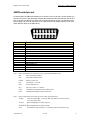
Tuning the T7 : SAAB I-bus communication
Analyzing Trionic 7 with T7Suite
SAAB I-bus communication
Courtesy of Tomili and General Failure
The I-Bus is an internal bus (Instrumentation Bus) that connects together instruments such as the
radio, ACC and the SID (Information Display). The I-bus is the non-critical bus which means that
vehicle critical information is not sent over it. That is done through the P (powertrain) bus.
The I-bus enables us to communicate with several devices in the car including the TWICE, DICE etc.
Both the I and the P bus are CAN bus based communication buses which enables us to use a normal
CAN adapter to interface with them.
The I bus follows the ISO 11898-2 standard which is the high speed variant, although it only
implements a maximum communication speed of 47,619 Kbit/s. Messages on a CAN bus are sent
within CAN frames that include an identifier number, number of data bytes, the actual data (called the
payload) and checksum (to verify it the data was transferred correctly). There are two CAN frame
formats: the basic frame (referred to as CAN2.0A) and the extended frame (referred to as CAN2.0B).
The basic frame has a 11-bit identifier field, when the extended frame has a 29-bit identifier which
makes it possible to extend the number of message types that can be sent over the bus.
The I bus uses two signal (just like any other CAN bus connection) which are called I+ and I-. These
refer to CAN High and CAN Low signals in general CAN terminology.
Details on I bus communication:
Frame type:
Bus speed:
Timing register settings:
CAN 2.0A (11-bit identifiers)
47,619 Kbit/s
BTR0 0xCB, BTR1 0x9A
As an example the engine speed is located as a 16-bit integer value on message ID 460h
(hexadecimal) in the second and third bytes (I define first byte as the most significant byte). Speed is
in the same message in fourth and fifth bytes. The speed value is multiplied by ten, so you have to
divide the 16-bit integer by 10 to get the real speed value.
Here's an example ID 460h message: 00 03 9C 00 2A 00 00 00
Engine rpm is 039Ch (hexadecimal format) = 924 (decimal format) = 942 RPM
Speed is 002Ah = 42 = 4,2 km/h
220h - Trionic data initialization
This message must be sent before any queries to the Trionic can be sent. Trionic responds with a
238h message.
ID
Byte 0
Byte 1
Byte 2
Byte 3
Byte 4
Byte 5
Byte 6
Byte 7
220h
3Fh
81h
01h
33h
02h
40h
00h
00h
238h - Trionic data initialization reply
Trionic sends this message after a 220h message has been sent on the bus.
ID
Byte 0
Byte 1
Byte 2
Byte 3
Byte 4
Byte 5
Byte 6
Byte 7
238h
40h
BFh
21h
C1h
01h
11h
02h
58h
© Dilemma 2010
rev 1.06
55
Tuning the T7 : SAAB I-bus communication
Analyzing Trionic 7 with T7Suite
240h - Trionic data query
This message is sent as a command to the Trionic. It can be used to query "OBD-II" information. I
use the quotation marks because basically this information is also available from the OBD-II interface.
The problem with the OBD-II interface is that it's slow. By using directly the I-Bus (or even better, the
P-Bus) you can achieve refresh rates 10 Hz...~50 Hz. The DATA byte below indicates what data is
requested. The COMMAND byte is 01h for requesting OBD-II information. With COMMAND byte as
1Ah you can request information from the Trionic software header. The header comprises of ASCII
and hexadecimal data about e.g. Vehicle Identification Number (VIN), Immobilizer code, Software
Saab part number, Hardware Saab part number and Software version string.
ID
Byte 0
Byte 1
Byte 2
Byte 3
Byte 4
Byte 5
Byte 6
Byte 7
240h
40h
A1h
02h
COMMAND
DATA
00h
00h
00h
Here's a list of DATA values you can query (that I know of) with the COMMAND byte as 01h.
DATA
Description
How to handle reply value
00h
04h
05h
0Bh
0Ch
0Eh
0Fh
10h
14h
15h
Some generic request (requires more research)
Calculated load value
Coolant temperature
Manifold Air Pressure, MAP
Engine RPM
Engine timing advance
Intake air temperature
Mass Air Flow, MAF
O2 sensor 1, Bank 1
O2 sensor 2, Bank 1
?
unit is %
subtract 40, unit °C
unit hPa
divide by 4, unit 1/min
?
subtract 40, unit °C
divide by 100, unit g/s
?
?
When COMMAND is 1Ah, here's what you can get with the DATA byte.
DATA
Description
90h
91h
92h
94h
95h
97h
98h
99h
Vehicle Identification Number, VIN
Hardware Saab part number
Immobilizer code
Software Saab part number
Software version
Engine type
Additional info
Software date
Example messages:
240h [40 A1 02 01 10 00 00 00]
258h [C1 BF 04 41 00 00 00 00]
266h [40 A1 3F 81 00 00 00 00]
258h [80 BF 10 04 AB 00 00 00]
266h [40 A1 3F 80 00 00 00 00]
First, Mass Air Flow value is requested from the Trionic. It responds with a two row answer, to which
both rows are acknowledged. The MAF value is 4ABh, which translates to 1195dec, so the actual value
is 11.95 g/s.
© Dilemma 2010
rev 1.06
56
Tuning the T7 : SAAB I-bus communication
Analyzing Trionic 7 with T7Suite
258h - Trionic data query reply
Trionic sends these reply messages after receiving a 240h data query. There are several different
ways the Trionic can respond. Below are three different ones. The ROW byte tells the row index of the
reply (i.e. how many messages are still coming). It always seems to have the most significant bit, bit
7 set. Also, the first row has bit 6 set. So, a one line reply has a ROW byte of C0h, two line has ROW
bytes C1h and 80h, three line has C2h, 81h, 80h, and so on. The LENGTH byte gives the length of the
answer. However there's something a bit illogical about the LENGTH byte, since in the first response
way detailed below, the LENGTH byte is either 03h or 04h. In the last response way LENGTH is
logical, it tells the number of REPLY bytes plus two (5Ah and DATA byte). The last reply row is padded
with 00h's if necessary.
ID
Byte 0
Byte 1
Byte 2
Byte 3
Byte 4
Byte 5
Byte 6
Byte 7
258h
258h
ROW
ROW
BFh
BFh
LENGTH
DATA
41h
VALUE1
00h
[VALUE0]
00h
00h
00h
00h
00h
00h
Example messages:
240h [40 A1 02 01 0B 00 00 00]
258h [C1 BF 03 41 00 00 00 00]
266h [40 A1 3F 81 00 00 00 00]
258h [80 BF 0B 64 00 00 00 00]
266h [40 A1 3F 80 00 00 00 00]
Asks Manifold Air Pressure, MAP, from Trionic, with a response of 64h or 100dec (100 hPa).
ID
Byte 0
Byte 1
Byte 2
Byte 3
Byte 4
Byte 5
Byte 6
Byte 7
258h
ROW
BFh
LENGTH
41h
DATA
VALUE1
[VALUE0]
00h
Example messages:
240h [40 A1 02 01 0C 00 00 00]
258h [C0 BF 04 41 0C 24 DC 00]
266h [40 A1 3F 80 00 00 00 00]
Asks Engine RPM from Trionic, with a response of 24DCh or 9436dec. Divide by 4 and you get 2359
RPM.
ID
Byte 0
Byte 1
Byte 2
Byte 3
Byte 4
Byte 5
Byte 6
Byte 7
258h
258h
258h
ROW
ROW
ROW
BFh
BFh
BFh
LENGTH
REPLY
REPLY
5Ah
REPLY
REPLY
DATA
REPLY
REPLY
REPLY
REPLY
REPLY
REPLY
REPLY
REPLY
REPLY
REPLY
REPLY
Example messages:
240h [40 A1 02 1A 90 00 00 00]
258h [C3 BF 13 5A 90 59 53 33] YS3
266h [40 A1 3F 83 00 00 00 00]
258h [82 BF 45 46 35 38 43 39] EF58C9
266h [40 A1 3F 82 00 00 00 00]
258h [81 BF 59 31 32 33 34 35] Y12345
266h [40 A1 3F 81 00 00 00 00]
258h [80 BF 36 37 00 00 00 00] 67
266h [40 A1 3F 80 00 00 00 00]
Asks Vehicle Identification Number from Trionic, with a response of YS3EF58C9Y1234567.
© Dilemma 2010
rev 1.06
57
Tuning the T7 : SAAB I-bus communication
Analyzing Trionic 7 with T7Suite
266h - Trionic reply acknowledgement
This message must be sent after every Trionic data query reply. Notice that bit 6 (which tells if this is
the first reply row) of ROW byte is cleared in this acknowledgement message.
ID
Byte 0
Byte 1
Byte 2
Byte 3
Byte 4
Byte 5
Byte 6
Byte 7
266h
40h
A1h
3Fh
ROW
00h
00h
00h
00h
Example messages:
240h [40 A1 02 01 0C 00 00 00]
258h [C1 BF 04 41 00 00 00 00]
266h [40 A1 3F 81 00 00 00 00]
258h [80 BF 0C 17 58 00 00 00]
266h [40 A1 3F 80 00 00 00 00]
The first 266h response is with 81h in the ROW byte and the second with 80h.
280h - Pedals, reverse gear
Message is sent with an interval of 1 second and if a value changes. The most significant bit of the
first byte (byte 0) is set if information has changed from the last message. The GEAR byte is 02h if
the reverse gear selected, otherwise the byte is FFh. When the brake pedal is pressed lightly only bit 1
of the PEDAL byte will be set. Normal braking will set bits 1, 3 and 4. The BRAKE/CLUTCH bit will also
be set if the clutch is pressed. The ACTIVE bit in the CRUISE byte is set when cruise control has been
activated. The ?? byte indicates that the engine is running or something like that (needs closer
inspection).
ID
Byte 0
Byte 1
Byte 2
Byte 3
Byte 4
Byte 5
Byte
6
Byte 7
280
h
STATE
GEAR
PEDAL
-
CRUISE
??
-
-
Byte
Bit 7
Bit 6
Bit 5
Bit 4
Bit 3
Bit
2
Bit 1
Bi
t
0
STATE
CHANGE
D
-
-
-
-
-
-
-
-
-
KICKDOW
N
ACTIVE
BRAK
E
-
BRAKE/CLUTC
H
-
-
BRAK
E
-
-
PEDAL
CRUISE
Example message:
80 FF 0A 00 00 C0 82 00
-
-
-
Information has changed from the last message, reverse gear is not selected, brake pedal has been
pressed and the engine is running (?).
© Dilemma 2010
rev 1.06
58
Tuning the T7 : SAAB I-bus communication
Analyzing Trionic 7 with T7Suite
290h - Steering wheel and SID buttons
Message is sent with an interval of 1 second and if a value changes. The most significant bit of the
first byte (byte 0) is set if information has changed from the last message. The audio button
information and SID button information are duplicated to bytes 4 and 5.
ID
Byte 0
Byte 1
Byte 2
Byte 3
Byte 4
Byte 5
Byte
6
Byte
7
290h
STATE
-
AUDIO
SID
AUDIO
SID
-
-
Byte
Bit 7
Bit 6
Bit 5
Bit 4
Bit 3
Bit 2
Bit 1
Bit 0
STATE
AUDIO
SID
CHANGED
VOLCLR
VOL+
SET
SRC
DOWN
SEEK+
UP
SEEKNPANEL
NXT
CLOCK+
CLOCK-
-
Example message:
80 00 40 00 40 00 00 00
Information has changed from the last message and the Volume Up audio button has been pressed.
320h - Doors, central locking and seat belts
Message is sent with an interval of 1 second and if a value changes. The most significant bit of the
first byte (byte 0) is set if information has changed from the last message. Bit LOCKED is 1 if doors
are locked. Bit FL reports if the front left door is open, FR reports the same from the front right door
(RL and RR bits indicate the rear doors). Bit TRUNK reports if the trunk is open. The BULBS byte
indicates if there are any broken light bulbs, that the SID should report (Information provided by
Magnus Lirell).
ID
Byte 0
Byte 1
Byte 2
Byte 3
Byte 4
Byte 5
Byte 6
Byte 7
320h
STATE
DOOR
BELT
-
BULBS
-
-
-
Byte
Bit 7
Bit 6
Bit 5
Bit 4
Bit 3
Bit 2
Bit 1
Bit 0
STATE
DOOR
BELT
BULBS
CHANGED
LOCKED
-
FL
Left park
FR
??
-
RL
??
-
RR
-
TRUNK
-
-
-
Example message:
00 E0 00 00 00 CC 80 00
Information has not changed from the last message and both front doors are open.
328h - SID audio text
A group of three messages are sent with an interval of 1 second and if a value changes. Messages are
sent with about 10 milliseconds apart. The CHANGED bit in the ROW byte will be set if information
changes. The two bits ORD0 and ORD1 in the ORDER byte are for sequence numbering. A new
message group starts with the NEW bit set and both ORD0 and ORD1 bits. On the second message
the NEW and ORD1 bits are cleared and the third message has also the ORD0 bit cleared. So the
ORDER byte will be 42, 01 and 00 for the three sequential messages. The ROW byte tells to which
row of the SID the text will be displayed on. The byte can have a value of 2 or 1, but in these audio
text messages the row number is always 2. The TEXT4...TEXT0 bytes are plain ASCII coded
characters that will be displayed on the SID.
© Dilemma 2010
rev 1.06
59
Tuning the T7 : SAAB I-bus communication
Analyzing Trionic 7 with T7Suite
Note that the last message will contain only one normal character in the TEXT4 byte. The TEXT3 byte
should contain a integer value that will be shown as a small number to indicate the selected radio
station number. The last TEXT2...TEXT0 bytes are always zeros.
ID
Byte 0
Byte 1
Byte 2
Byte 3
Byte 4
Byte 5
Byte 6
Byte 7
328h
ORDER
-
ROW
TEXT4
TEXT3
TEXT2
TEXT1
TEXT0
Byte
Bit 7
Bit 6
Bit 5
Bit 4
Bit 3
Bit 2
Bit 1
Bit 0
ORDER
ROW
CHANGED
NEW
-
-
-
-
-
ORD1
ROW1
ORD0
ROW0
Example message group:
42 96 02 55 31 20 4B 49 U 1 _ K I
01 96 02 53 53 20 46 4D S S _ F M
00 96 02 20 01 00 00 00 _ 1
The text "U1 KISS FM " will be displayed on the SID display and the radio station number is 1.
32Ch - ACC to SID text
This message is identical to the 32Fh message. The only difference is that this message is sent by the
ACC (Automatic Climate Control).
Information provided by Magnus Lirell.
Example message group:
45 96 81 53 54 41 52 54 S T A R T
04 96 81 41 20 4D 4F 54 A _ M O T
03 96 81 4F 52 20 20 20 O R
02 96 82 46 D7 52 20 41 F Ö R _ A
01 96 82 43 43 20 20 20 C C
00 96 82 20 20 20 20 20
The text "STARTA MOTOR FÖR ACC" will be displayed on the SID display. This message should come
up when press Auto + OFF on the ACC with the ignition turned ON and motor not running.
32Fh - TWICE to SID text
This SID full-screen text message is almost identical to the previous 328h SID audio text message.
This 32Fh message is used by the TWICE (Theft Warning Integrated Central Electronics) to display
text on the SID. The row number can be one in this message. And the ORDER byte contains an ORD2
bit so that six messages can be sent. Also the last three bytes of messages #3 and #6 (that's with
ORDER bytes 03h and 06h) are 20h, not 00h like in the audio text message.
Example message group:
45 96 01 32 20 52 45 4D 2 _ R E M
04 96 01 4F 54 45 20 4B O T E _ K
03 96 01 45 59 20 20 20 E Y
02 96 02 32 20 54 52 41 2 _ T R A
01 96 02 4E 53 50 4F 4E N S P O N
00 96 02 44 52 20 20 20 D R
The texts "2 REMOTE KEY" and "2 TRANSPONDR" will be displayed on rows one and two of the SID
display.
337h - SPA to SID text
This message is identical to the previous 32Fh message. The only difference is that this message is
sent by the SPA (Saab Park Assist).
Information provided by Magnus Lirell.
Example message group:
© Dilemma 2010
rev 1.06
60
Tuning the T7 : SAAB I-bus communication
Analyzing Trionic 7 with T7Suite
42 96 01 50 41 52 4B 2E P A R K .
01 96 01 48 4A 15 4C 50 H J Ä L P
00 96 01 20 20 00 00 00 _ _
The text "PARK.HJÄLP" will be displayed on row one of the SID display.
348h - SID audio text control
Message is sent with an interval of 1 second. The normal value (i.e. don't display text) of byte
STATUS is FFh. When a 328h SID audio text message group is sent, the STATUS byte is changed to
04h and immediately after that to 05h for the duration of the messages. After the 328h messages, the
status byte returns to FFh.
Notice that the control messages use a 20h increment relative to the actual text messages in their
IDs. Bytes 0 and 3 probably have something to do with priority (which text is displayed if several texts
should be displayed at the same time).
ID
Byte 0
Byte 1
Byte 2
Byte 3
Byte 4
348h
11
02
STATUS
19
00
Example message:
11 02 FF 19 00 00 00 00
SID should not display the text provided with message 328h.
Byte 5
Byte 6
Byte 7
00
00
00
34Ch - ACC to SID text control
Message is sent with an interval of 1 second. The normal value of byte STATUS is FFh. When a 32Ch
ACC to SID text message group is sent, the STATUS byte changes between 03h and 05h for the
duration of the messages. After the 32Ch messages, the status byte returns to FFh. Byte UNKNOWN1
seems to stay at 00h and UNKNOWN2 byte at 23h.
Information provided by Magnus Lirell.
ID
Byte 0
Byte 1
Byte 2
Byte 3
Byte 4
Byte 5
Byte 6
Byte 7
34Ch
18
UNKNOWN1
STATUS
UNKNOWN2
00
00
00
00
Example message:
18 00 05 23 00 00 00 00
.
.
18 00 FF 23 00 00 00 00
First line: requesting SID to display text provided with message 32Ch. Second line: SID should not
display ACC text.
34Fh - TWICE to SID text control
Message is sent with an interval of 1 second. The normal value of byte STATUS is FFh. When a 32Fh
TWICE to SID text message group is sent, the STATUS byte is changed to 04h and immediately after
that to 05h for the duration of the messages. After the 32Fh messages, the status byte returns to FFh.
ID
Byte 0
Byte 1
Byte 2
Byte 3
Byte 4
34Fh
1B
00
STATUS
2D
00
Example message:
1B 00 05 2D 00 00 00 00
Requesting SID to display text provided with message 32Fh.
Byte 5
Byte 6
Byte 7
00
00
00
357h - SPA to SID text control
Message is sent with an interval of 1 second. The normal value of byte STATUS is FFh. When a 337h
SPA to SID text message group is sent, the STATUS byte is changed to 04h and immediately after
that to 05h for the duration of the messages. After the 337h messages, the status byte returns to FFh.
© Dilemma 2010
rev 1.06
61
Tuning the T7 : SAAB I-bus communication
Analyzing Trionic 7 with T7Suite
Byte UNKNOWN1 is 00h when STATUS is FFh and 01h when STATUS is 05h. UNKNOWN2 byte also
changes from 08h (STATUS is FFh) to 12h (STATUS is 05h).
ID
Byte 0
Byte 1
Byte 2
Byte 3
Byte 4
Byte 5
Byte 6
Byte 7
357h
1F
UNKNOWN1
STATUS
UNKNOWN2
00
00
00
00
Example message:
1F 01 05 12 00 00 00 00
.
.
1F 00 05 08 00 00 00 00
First line: requesting SID to display text provided with message 337h. Second line: SID should not
display SPA text.
368h - SID text priority
Message is sent with an interval of 1 second and if a value changes. Message is sent in a group of
three messages. The first byte, ROW, has the values 0h, 1h, 2h corresponding to lines on the SID.
The 0h line needs more research, since as you know the SID has only two lines of text it can display.
If the PRIORITY byte is FFh, there is nothing shown on the SID. However, when a control unit sends
text messages (e.g. messages 337h and 357h), its requested priority is shown on the PRIORITY byte.
If another control unit wants to override the currently shown text message, it needs to send messages
with a higher priority, i.e. with a lower PRIORITY byte value.
Information provided by David Goncalves.
ID
Byte 0
Byte 1
Byte 2
Byte 3
Byte 4
368h
ROW
PRIORITY
Example message group:
00 FF 00 00 00 00 00 00
01 FF 00 00 00 00 00 00
02 19 00 00 00 00 00 00
SID shows text on row 2 with priority 19h. No text on row 0 and 1.
Byte 5
Byte 6
Byte 7
-
-
-
380h - Audio RDS status
Message is sent with an interval of 1 second and if a value changes. This message tells the RDS status
of the Audio system.
Information provided by David Goncalves.
ID
Byte 0
Byte 1
Byte 2
Byte
3
Byte 4
Byte 5
Byte
6
Byte 7
380h
STATE
UNKNOWN
STATUS
-
-
-
-
-
Byte
Bit 7
Bit 6
Bit 5
Bit 4
Bit 3
Bit 2
Bit 1
Bit 0
STATE
STATUS
CHANGED
RDS
No TP
??
TP
PTY
??
??
No RDS
activ.
signal
activ.
activ.
signal
Example message group:
80 00 D0 00 00 00 00 00
RDS has been activated and the radio is receiving a RDS signal, TP has been activated but no TP
signal received.
© Dilemma 2010
rev 1.06
62
Tuning the T7 : SAAB I-bus communication
Analyzing Trionic 7 with T7Suite
3B0h - Head lights
Message is sent with an interval of 1 second and if a value changes. The most significant bit of the
first byte (byte 0) is set if information has changed from the last message. LIGHT byte indicates the
park and daylight head-lights with the PARK and DAY bits. When ignition signal is off, the OFF bit is
set in the LIGHT byte. The ?? byte is 20h when ignition signal is off and B8h when the signal is on.
ID
Byte 0
Byte 1
Byte 2
Byte 3
Byte 4
Byte 5
Byte 6
Byte 7
3B0h
STATE
LIGHT
-
??
-
-
-
-
Byte
Bit 7
Bit 6
STATE
CHANGED
LIGHT
1
??
Example message:
00 76 74 B8 00 00 00 00
Information has not changed from the
Bit 5
Bit 4
Bit 3
Bit 2
Bit 1
Bit 0
1
-
1
-
OFF
-
1
-
PARK
-
DAY
-
last message and the head-lights are in park mode.
3C0h - CD Changer control
Message is sent with an interval of 1 second. The most significant bit of the first byte, CHANGED,
indicates when information has changed in the message. Byte 1, COMMAND, specifies what CD
Changer controlling button has been pressed. The PARAM byte is used by "Change to CD" command
to inform which CD was selected.
ID
Byte 0
Byte 1
Byte 2
Byte 3
Byte 4
Byte 5
Byte 6
Byte 7
3C0h
CHANGED
COMMAND
PARAM
-
-
-
-
-
COMMAND
Description
59h
35h
36h
68h
B0h
B1h
76h
Next (NXT button)
Seek next (Seek+)
Seek previous (Seek-)
Change to CD according to PARAM byte
Audio mute (off?)
Audio mute (on?)
Random play (long press of CD/RDM
button)
Example message:
80 68 02 00 00 00 00 00
Information has changed since last message and CD 2 has been selected to be played.
3C8h - CD Changer information
Message is sent with an interval of 1 second. The most significant bit of the first byte, CHANGED,
indicates when information has changed in the message. MAGAZINE byte informs which disc slots are
occupied and which are empty. The lower nibble of DISC byte (DISC3...DISC0) tells which CD disc is
being played in BCD coding. TRACK byte tells the track number being played in BCD coding. The bytes
MIN and SEC tell the play minutes and seconds of the current track, also in BCD coding. When there's
no disc in play, the TRACK, MIN and SEC bytes are FFh. The STAT0...STAT2 bits indicate the status of
the CD changer. If the STAT value is 0h, the CD changer is inactive (not spinning). Value 3h means
power-up / spin-up, but not ready yet. And value 4h means that everything is OK - playing disc.
SECURITY byte informs the Audio head unit if the CD Changer has not been married or is married to a
different car. If the byte is D0h, everything is alright. Values 50h and 10h mean that the CD Changer
needs to be married to the car (text "CDC CODE" will be displayed on SID). Value 90h means the CD
© Dilemma 2010
rev 1.06
63
Tuning the T7 : SAAB I-bus communication
Analyzing Trionic 7 with T7Suite
Changer has been married to a different car and the VIN doesn't correspond to the one stored in the
CD Changer (text "CDC LOCKED" will be display on SID).
ID
Byte 0
Byte
1
Byte 2
Byte 3
Byte 4
Byte
5
Byte
6
Byte 7
3C8
h
CHANGED
-
MAGAZINE
DISC
TRACK
MIN
SEC
SECURIT
Y
Byte
Bit 7
Bit 6
Bit 5
Bit 4
Bit 3
Bit 2
Bit 1
Bit 0
CHANGED
CHANGE
D
-
-
??
-
-
-
-
-
STAT2
CD6
STAT
1
CD5
STAT
0
CD4
DISC
3
CD3
DISC
2
CD2
DISC
1
CD1
DISC0
MAGAZINE
DISC
Example message:
20 00 17 45 33 01 53 D0
Information has not changed since last message and CD slots 4 and 6 are empty. The current track,
number 33, is being played from disc 5 and has lasted 1 minute and 53 seconds. The CD Changer has
been married and is operating in the married car.
3E0h - Automatic Gearbox
Message is sent with an interval of 1 second and if a value changes. The most significant bit of the
first byte (byte 0) is set if information has changed from the last message. The GEAR byte indicates in
what state the gearbox is. Value 05h means Forward, value 03h Neutral and value 02h Reverse. The
GEAR SHIFT byte tells in what position the gear shift is. Value 01h means Park, value 02h Reverse,
value 03h Neutral, value 04h Drive, value 08h "limit to 4", value 07h "limit to 3" and value 06h "low
speed gear".
Information provided by Magnus Lirell.
ID
Byte 0
Byte 1
Byte 2
Byte
3
Byte 4
Byte 5
Byte 6
Byte 7
3E0
h
STATE
GEARBOX
GEAR
SHIFT
MOD
E1
Adaptation?
MODE
2
-
-
Byte
Bit 7
Bit 6
B
it
5
Bit
4
Bit 3
Bit 2
Bit 1
Bit 0
STATE
CHANGE
D
-
-
-
-
-
-
-
-
-
-
-
-
-
-
-
-
-
-
-
POS
POS
POS
POS
-
-
-
-
-
-
SPORT/WINTE
R
SPORT/WINTE
R
GEARBO
X
GEAR
SHIFT
MODE2
Example message:
00 00 00 00 00 00 00 00
Example text...
© Dilemma 2010
rev 1.06
64
Tuning the T7 : SAAB I-bus communication
Analyzing Trionic 7 with T7Suite
410h - Light dimmer and light sensor
Message is sent with an interval of 1 second and if a value changes. The most significant bit of the
first byte (byte 0) is set if information has changed from the last message. DIMM1 and DIMM0 form a
16-bit integer for instrumentation panel dimmer position. Integer value is between about 4600h and
FD00h. LIGHT1 and LIGHT0 form also a 16-bit integer for the SID light sensor. Typical values range
from about 1800h to 2C00h. The NPANEL byte indicates if the Night Panel function is on (Information
provided by Magnus Lirell).
ID
Byte 0
Byte 1
Byte 2
Byte 3
Byte 4
Byte 5
Byte 6
Byte 7
410h
STATE
DIMM1
DIMM0
LIGHT1
LIGHT0
NPANEL
-
-
Byte
Bit 7
Bit 6
Bit 5
Bit 4
Bit 3
Bit 2
Bit 1
Bit 0
STATE
CHANGED
Example message:
00 46 41 18 04 00 00 00
Information has not changed from the last message and dimmer is at minimum position.
430h - SID beep request
This message is sent when the SID is requested to beep (what unit sends this request is still
unknown).
ID
Byte 0
Byte 1
430h
80
04
Example message:
80 04 00 00 00 00 00 00
Request for the SID to beep.
Byte 2
Byte 3
Byte 4
Byte 5
Byte 6
Byte 7
00
00
00
00
00
00
439h - SPA distance
Message is sent with an interval of ??. The DIST byte indicates the distance to objects behind the car
according to the SPA (Saab Park Assist).
Information provided by Magnus Lirell.
ID
Byte 0
439h
STATE
Example message:
00 00 00 00 00 00 00 00
Example text...
Byte 1
Byte 2
Byte 3
Byte 4
Byte 5
Byte 6
Byte 7
-
DIST
-
-
-
-
-
460h - Engine rpm and speed
Message is sent with an interval of 100 milliseconds. The ENGOFF bit of the first ENG byte indicates if
the engine is off (the bit is 0 when engine is on). RPM1 and RPM0 form a 16-bit integer for engine
speed (in RPM). Integer value is between 0000h and 1B00h. SPD1 and SPD0 form also a 16-bit
integer for the car speed. The unit for the value is 100 meters per hour, so in order to get speed in
kilometers per hour you must divide the integer value by ten.
ID
Byte 0
Byte 1
Byte 2
Byte 3
Byte 4
Byte 5
Byte 6
Byte 7
460h
ENG
RPM1
RPM0
SPD1
SPD0
-
-
-
Byte
Bit 7
Bit 6
Bit 5
Bit 4
Bit 3
Bit 2
Bit 1
Bit 0
-
-
-
-
-
-
-
ENG
ENGOFF
Example message:
© Dilemma 2010
rev 1.06
65
Tuning the T7 : SAAB I-bus communication
Analyzing Trionic 7 with T7Suite
00 03 9C 00 2A 00 00 00
Engine is running, engine speed is 924 RPM and car speed 4,2 km/h.
4A0h - Steering wheel, Vehicle Identification Number
Message is sent with an interval of 1 second and if a value changes. The most significant bit of the
first byte (byte 0) is set if information has changed from the last message. The WIPER byte indicates
the position of the windshield wiper control. The least significant bit of the WIPER byte indicates that
the park lights are on. The LEFT and RIGHT bits of the SIGNAL byte indicate if a signal light is on. So
when the signal light blinks, so does the bits. The REARFOG bit indicates if the rear fog light is on.
Vehicle Identification Number, VIN, is transmitted on bytes 4...6 (VIN2...VIN0). To be more precise,
the car serial number part of the VIN is transmitted. It is coded so that the last number of the VIN,
which probably is a checksum, is moved to the upper part of the first (VIN2) byte. For example if your
VIN is YS3DC55C612123456, your serial number part is that in bold, 123456. The last number, 6, is
the checksum number. Moving it to the upper part of the VIN2 byte, the VIN bytes would be VIN2 =
61h, VIN1 = 23h, VIN0 = 45h.
ID
Byte 0
Byte 1
Byte 2
Byte 3
Byte 4
Byte 5
Byte 6
Byte 7
4A0h
STATE
WIPER
SIGNAL
-
VIN2
VIN1
VIN0
-
Byte
Bit 7
Bit 6
Bit 5
Bit 4
Bit 3
Bit 2
Bit 1
Bit 0
STATE
CHANGED
WIPER
DRIZZLE
NORMAL
BACK
PARK
SIGNAL
LEFT
RIGHT
REARFOG
Example message:
80 41 00 00 61 23 45 00
Information has changed from the last message and the windshield wiper is in drizzle mode. The
Vehicle Identification Number's serial number part is 123456.
520h - ACC, inside temperature
Message is sent with an interval of 1 second. Inside temperature is reported with the 8-bit byte TEMP.
In order to get the correct temperature, the value must be subtracted with 40. This is done to encode
negative temperatures. So a value of 58 (3Ah) is in fact +18 degrees Celsius and on the other hand a
value of 29 (1Dh) would give an temperature of -11 degrees Celsius. The REARHEAT bit in the ACC
byte indicates if the rear window heater is on.
ID
Byte 0
Byte 1
Byte 2
Byte 3
Byte 4
Byte 5
Byte 6
Byte 7
520h
-
ACC
-
-
-
TEMP
-
-
Byte
Bit 7
Bit 6
Bit 5
Bit 4
Bit 3
Bit 2
Bit 1
Bit 0
ACC
REARHEAT
Example message:
00 00 00 00 00 3A 00 00
Inside temperature is 18 degrees Celsius.
-
-
-
-
-
© Dilemma 2010
rev 1.06
66
Tuning the T7 : SAAB I-bus communication
Analyzing Trionic 7 with T7Suite
530h - ACC
Message is sent with an interval of 1 second. The ACCON bit in the ACC byte tells if the ACC
(Automatic Climate Control) is turned on. When the bit is set, the ACC is on and when the bit is
cleared the ACC has been turned off. ACPRESS byte shows the A/C Pressure (unit is bar).
ID
Byte 0
Byte 1
Byte 2
Byte 3
Byte 4
Byte 5
Byte 6
Byte 7
530h
-
ACC
-
ACPRESS
-
-
-
-
Byte
Bit 7
Bit 6
ACC
Example message:
00 00 00 00 00 00 00 00
Text here.
Bit 5
Bit 4
Bit 3
Bit 2
Bit 1
Bit 0
-
-
-
ACCON
-
-
590h - Position Seat Memory
Message is sent with an interval of 1 second and if a value changes. The most significant bit of the
first byte (byte 0) is set if information has changed from the last message.
Information provided by Magnus Lirell.
ID
Byte 0
Byte 1
Byte 2
Byte 3
Byte 4
Byte 5
Byte 6
Byte 7
590h
STATE
MEM
-
-
-
-
-
-
Byte
Bit 7
Bit 6
Bit 5
Bit 4
Bit 3
STATE
CHANGED
MEM
Example message:
80 05 00 0 00 00 00 00
Store current seat and mirror positions into memory number 1.
Bit 2
Bit 1
Bit 0
STORE
MEM1
MEM0
5C0h - Coolant temperature, air pressure
Message is sent with an interval of 1 second. Temperature is reported with a 8-bit byte. In order to
get the correct coolant temperature, the value must be subtracted with 40. This is done to encode
negative temperatures. So a value of 58 (3Ah) is in fact +18 degrees Celsius and on the other hand a
value of 29 (1Dh) would give an temperature of -11 degrees Celsius. The 16-bit value combined from
PRES1 and PRES0 gives the Ambient air pressure in hehtopascals [hPa].
ID
Byte 0
Byte 1
Byte 2
Byte 3
Byte 4
Byte 5
5C0h
COOLANT
PRES1
PRES0
Example message:
00 6A 6A 03 F9 00 00 00
Coolant temperature is 66 degrees Celsius and air pressure is 1017 hPa.
Byte 6
Byte 7
-
-
630h - Fuel usage
Message is sent with an interval of 1 second. Fuel usage since last start is reported with an 16-bit
integer value (bytes FUEL1...FUEL0). The FUEL1 byte is the most significant byte. The unit is milliliters
of fuel (used since start). The amount of fuel left in the tank is indicated by 16-bit integer values
AVGTANK and TANK. The TANK value seems to be a raw measurement value and the AVGTANK an
averaged value of the raw measurements. A full tank is about 02A0h and a soon empty tank below
0040h. Dividing the value by 10 could give the available fuel amount in liters (this is a guess). The
first byte VALID at least informs if the tank values should be disregarded. For example during a
© Dilemma 2010
rev 1.06
67
Tuning the T7 : SAAB I-bus communication
Analyzing Trionic 7 with T7Suite
engine start the two least significant bits (TANKVALID) are set, meaning that the AVGTANK and TANK
values are not correct (they seem to be zeros).
ID
Byte
0
Byte 1
Byte 2
Byte 3
Byte 4
Byte 5
Byte 6
Byte 7
630h
VALID
FUEL1
FUEL0
AVGTANK1
AVGTANK0
TANK1
TANK0
-
Byte
Bit 7
Bit 6
Bit
5
Bit 4
Bit 3
Bit 2
Bit 1
Bit 0
VALID
-
-
-
-
??
??
TANKVALID
TANKVALI
D
Example message:
00 00 00 00 00 00 00 00
Example text here.
640h - Mileage
Message is sent with an interval of 1 second. Mileage is reported with an 24-bit integer value (bytes
MIL2...MIL0). The unit is 10 meters, so in order to get the mileage in kilometers the value must be
divided by a hundred.
ID
Byte 0
Byte 1
Byte 2
640h
MIL2
Example message:
00 00 CA A1 DC 00 00 00
Traveled mileage is 132 797,08 kilometers.
Byte 3
Byte 4
Byte 5
Byte 6
Byte 7
MIL1
MIL0
-
-
-
6A1h - Audio head unit
The Audio head unit uses messages with ID 6A1h to communicate with the CD changer. Byte 3 seems
to be the command for the CD changer. Value 13h is power-up / spin-up, value 12h play and 18h
power-down / spin-down.
ID
Byte 0
6A1h
21
Example message:
Example description.
Byte 1
Byte 2
Byte 3
Byte 4
Byte 5
Byte 6
Byte 7
00
00
COMMAND
01
??
??
-
6A2h - CD changer
The CD changer uses messages with ID 6A2h to communicate with the Audio head unit.
ID
Byte 0
6A2h
Example message:
Example description.
Byte 1
Byte 2
Byte 3
Byte 4
Byte 5
Byte 6
Byte 7
-
-
-
-
-
-
-
720h - RDS time
Message is sent with an interval of 1 second. The RDSON byte indicates if a RDS signal has been
detected.
Information provided by Magnus Lirell.
ID
Byte 0
Byte 1
Byte 2
Byte 3
Byte 4
Byte 5
Byte 6
Byte 7
720h
-
SEC
MIN
HOUR
DAY
MONTH
RDSON
-
© Dilemma 2010
rev 1.06
68
Tuning the T7 : SAAB I-bus communication
Analyzing Trionic 7 with T7Suite
Example message:
00 01 0E 13 0F 02 E1 00
The day is the 16th of February and the time is 19:14:01.
© Dilemma 2010
rev 1.06
69
Tuning the T7 : SAAB I-bus communication
Analyzing Trionic 7 with T7Suite
730h – Clock
Message is sent with an interval of 8 seconds. The ENGCOLD byte indicates how many minutes has
passed since the ignition was turned off.
ID
Byte 0
Byte 1
Byte 2
Byte 3
Byte 4
Byte 5
730h
SEC
MIN
HOUR
DAY
MONTH
Example message:
00 01 0E 13 0F 02 00 00
The day is the 16th of February and the time is 19:14:01.
Byte 6
Byte 7
ENGCOLD
-
740h 750h - Security
Messages are sent when the car key is turned to ignition on. This leads me to believe that these two
messages are somehow connected to the anti-theft system. The CODE bytes seem to have random
numbers in them that change after a successful "handshake".
The 750h message is sent first and after about 20 ms the 740h message is sent. The "reply" can
contain zeroed CODE bytes and the STATUS byte as FFh. In that case after about 190 ms the same
750h message is repeated. The second 740h "reply" seems to be always ok, since it has something in
the CODE bytes and the STATUS byte is 55h.
ID
Byte 0
Byte 1
740h
CODE4?
CODE3?
750h
CODE4?
CODE3?
Example messages:
750 4F C3 11 2A FA 00 00 00
740 FE 91 EA 5C CD 55 00 00
Byte 2
Byte 3
Byte 4
Byte 5
Byte 6
Byte 7
CODE2?
CODE2?
CODE1?
CODE1?
CODE0?
CODE0?
STATUS
00
00
00
00
00
750 7E EE 9B FF 6E 00 00 00
740 00 00 00 00 00 FF 00 00
750 7E EE 9B FF 6E 00 00 00
740 58 67 92 77 4F 55 00 00
750 21 E9 FF F8 4A 00 00 00
740 00 00 00 00 00 FF 00 00
750 21 E9 FF F8 4A 00 00 00
740 2C DB 4A 7E 49 55 00 00
750 14 20 42 C7 C3 00 00 00
740 00 00 00 00 00 FF 00 00
750 14 20 42 C7 C3 00 00 00
740 04 B9 29 D2 03 55 00 00
In this example the first column indicates the message ID. These are real-world examples of the
messages. If someone figures out how these messages work, it could mean that the anti-theft
mechanism could be bypassed.
7A0h - Outside temperature
Message is sent with an interval of 1 second. There are two temperature values: AVGTEMP and
RAWTEMP. AVGTEMP is the averaged outside temperature with a reading accuracy of 1 degree
Celsius. The other temperature, RAWTEMP, shows the raw temperature readings. It has a reading
accuracy of 0.5 degrees Celsius. Temperatures are reported as 16-bit values. In order to get the
correct temperature, the value must be divided by 10 and subtracted with 40. In other words, a value
of 0235h is first converted to decimal, 565, then divided by 10, so that we get 56.5 and finally
subtract 40 to get 16.5 degrees Celsius. The STATUS byte most likely tells if the temperature readings
are inside or outside values. The SID seems to display the inside temperature for some time. During
© Dilemma 2010
rev 1.06
70
Tuning the T7 : SAAB I-bus communication
Analyzing Trionic 7 with T7Suite
this time the STATUS byte is 30h. After the a while the STATUS bytes changes to first to 80h and then
right after to 00h. This probably means that the temperature readings are outside values.
ID
Byte 0
Byte 1
Byte 2
Byte 3
Byte 4
Byte
5
Byte
6
Byte
7
7A0h
STATUS
AVGTEMP1
AVGTEMP0
RAWTEMP1
RAWTEMP0
Example message:
00 01 72 01 6D 00 00 00
Average outside temperature is -4.0 degrees Celsius and raw outside temperature reading is -3.5
degrees Celsius.
© Dilemma 2010
rev 1.06
71
Tuning the T7 : SAAB P-bus communication
Analyzing Trionic 7 with T7Suite
SAAB P-bus communication
Courtesy of Tomili and General Failure
The P-Bus is an internal bus (Powertrain Bus) that connects together ECU, ABS control unit, TCS
control unit and DICE.
The I bus follows the ISO 11898-2 standard which is the high speed variant, it implements a
maximum communication speed of 500 kbit/s. Messages on a CAN bus are sent within CAN frames
that include an identifier number, number of data bytes, the actual data (called the payload) and
checksum (to verify it the data was transferred correctly). There are two CAN frame formats: the
basic frame (referred to as CAN2.0A) and the extended frame (referred to as CAN2.0B). The basic
frame has a 11-bit identifier field, when the extended frame has a 29-bit identifier which makes it
possible to extend the number of message types that can be sent over the bus.
The P bus uses two signal (just like any other CAN bus connection) which are called P+ and P-. These
refer to CAN High and CAN Low signals in general CAN terminology.
Details on P bus communication:
Frame type:
Bus speed:
Timing register settings:
CAN 2.0A (11-bit identifiers)
500 kbit/s
BTR0 0x00, BTR1 0x1C
1A0h - Engine information
Message is sent with an interval of 10 milliseconds. The ENGSTOPPED bit in the STATUS byte
indicates if the engine is running or stopped. Engine RPM is shown as a 16-bit value (RPM1 and
RPM0). MAP shows the Manifold Absolute Pressure in kilopascals. THROTTLE byte is the throttle pedal
position, with a value range of 0...100 percent (0...64hex). MAF is the reading from Mass Air Flow
sensor.
ID
Byte 0
Byte 1
Byte 2
Byte 3
1A0h
STATUS
RPM1
RPM0
MAP
Byte 4
Byte 5
Byte 6
Byte 7
THROTTLE
-
MAF
Byte
Bit 7
Bit 6
Bit 5
Bit 4
Bit 3
Bit 2
Bit 1
Bit 0
STATUS
CHANGED
-
-
-
ENGSTOPPED
-
-
-
2F0h - Vehicle speed
Message is sent with an interval of 20 milliseconds. Vehicle speed is indicated by the 16-bit value
(bytes SPEED1 and SPEED0). You will need to divide the value by 10 to get the right scaling,
kilometers per hour. The byte 3 seems to be 80h all the time.
ID
Byte 0
Byte 1
Byte 2
Byte 3
Byte 4
Byte 5
Byte 6
Byte 7
2F0h
-
SPEED1
SPEED0
?
-
-
-
-
280h - Pedals, reverse gear
Message is sent with an interval of 1 second and if a value changes. The most significant bit of the
first byte (byte 0) is set if information has changed from the last message. The GEAR byte is 02h if
the reverse gear selected, otherwise the byte is FFh. When the brake pedal is pressed lightly only bit 1
of the PEDAL byte will be set. Normal braking will set bits 1, 3 and 4. The BRAKE/CLUTCH bit will also
be set if the clutch is pressed. The ACTIVE bit in the CRUISE byte is set when cruise control has been
activated. The ?? byte indicates that the engine is running or something like that (needs closer
inspection).
ID
Byte 0
Byte 1
Byte 2
Byte 3
Byte 4
Byte 5
Byte
6
Byte 7
280
STATE
GEAR
PEDAL
-
CRUISE
??
-
-
© Dilemma 2010
rev 1.06
72
Tuning the T7 : SAAB P-bus communication
Analyzing Trionic 7 with T7Suite
h
Byte
Bit 7
Bit 6
Bit 5
Bit 4
Bit 3
Bit
2
Bit 1
Bi
t
0
STATE
CHANGE
D
-
-
-
-
-
-
-
-
-
KICKDOW
N
ACTIVE
BRAK
E
-
BRAKE/CLUTC
H
-
-
BRAK
E
-
-
PEDAL
CRUISE
Example message:
80 FF 0A 00 00 C0 82 00
Information has changed from the last message, reverse gear is not selected, brake pedal has been
pressed and the engine is running (?).
338h - Trionic to SID text
A group of three messages are sent with an interval of 1 second and if a value changes. Messages are
sent with about 10 milliseconds apart. The CHANGED bit in the ROW byte will be set if information
changes. The two bits ORD0 and ORD1 in the ORDER byte are for sequence numbering. A new
message group starts with the NEW bit set and both ORD0 and ORD1 bits. On the second message
the NEW and ORD1 bits are cleared and the third message has also the ORD0 bit cleared. So the
ORDER byte will be 42, 01 and 00 for the three sequential messages. The ROW byte tells to which
row of the SID the text will be displayed on. The byte can have a value of 2 or 1, but in these audio
text messages the row number is always 2. The TEXT4...TEXT0 bytes are plain ASCII coded
characters that will be displayed on the SID.
Note that the last message will contain only one normal character in the TEXT4 byte. The TEXT3 byte
should contain a integer value that will be shown as a small number to indicate the selected radio
station number. The last TEXT2...TEXT0 bytes are always zeros.
ID
Byte 0
Byte 1
Byte 2
Byte 3
Byte 4
Byte 5
Byte 6
Byte 7
338h
ORDER
-
ROW
TEXT4
TEXT3
TEXT2
TEXT1
TEXT0
Byte
Bit 7
Bit 6
Bit 5
Bit 4
Bit 3
Bit 2
Bit 1
Bit 0
ORDER
NEW
ORD1
ORD0
ROW
CHANGED
ROW1
ROW0
Example message group:
42 96 02 55 31 20 4B 49 U 1 _ K I
01 96 02 53 53 20 46 4D S S _ F M
00 96 02 20 01 00 00 00 _ 1
The text "U1 KISS FM " will be displayed on the SID display and the radio station number is 1.
358h - Trionic to SID text control
Message is sent with an interval of 1 second. The normal value of byte STATUS is FFh. When a 338h
Trionic to SID text message group is sent, the STATUS byte is changed to 04h and immediately after
that to 05h for the duration of the messages. After the 338h messages, the status byte returns to FFh.
Byte UNKNOWN1 is 00h when STATUS is FFh and 01h when STATUS is 05h. UNKNOWN2 byte also
changes from 08h (STATUS is FFh) to 12h (STATUS is 05h).
ID
Byte 0
Byte 1
358h
1F
UNKNOWN1
Example message:
1F 01 05 12 00 00 00 00
.
.
1F 00 05 08 00 00 00 00
© Dilemma 2010
Byte 2
Byte 3
Byte 4
Byte 5
Byte 6
Byte 7
STATUS
UNKNOWN2
00
00
00
00
rev 1.06
73
Tuning the T7 : SAAB P-bus communication
Analyzing Trionic 7 with T7Suite
First line: requesting SID to display text provided with message 338h. Second line: SID should not
display Trionic text.
370h - Mileage
Message is sent with an interval of 100 milliseconds. The 24-bit value (comprised of MIL2, MIL1 and
MIL0) shows the length that has been travelled since the engine was started. You will need to divide
the value by 100 to get right scaling (the value's unit is meters). The value 000069h seems to tell that
you haven't moved yet.
ID
Byte 0
Byte 1
Byte 2
370h
STATUS
MIL2
MIL1
Example message:
00 02 D1 50 00 00 00 00
You have travelled 1 846,56 meters.
Byte 3
Byte 4
Byte 5
Byte 6
Byte 7
MIL0
-
-
-
-
3A0h - Vehicle speed (MIU?)
Message is sent with an interval of 55 milliseconds. Vehicle speed is indicated by the 16-bit value
SPEED (bytes SPEED1 and SPEED0). You must divide the 16-bit value by 10 to get the value in
kilometers per hour.
ID
Byte 0
Byte 1
Byte 2
Byte 3
Byte 4
Byte 5
Byte 6
Byte 7
3A0h
-
-
-
SPEED1
SPEED0
-
-
-
3B0h - Head lights
Message is sent with an interval of 1 second and if a value changes. The most significant bit of the
first byte (byte 0) is set if information has changed from the last message. LIGHT byte indicates the
park and daylight head-lights with the PARK and DAY bits. When ignition signal is off, the OFF bit is
set in the LIGHT byte. The ?? byte is 20h when ignition signal is off and B8h when the signal is on.
ID
Byte 0
Byte 1
Byte 2
Byte 3
Byte 4
Byte 5
Byte 6
Byte 7
3B0h
STATE
LIGHT
-
??
-
-
-
-
Byte
Bit 7
Bit 6
STATE
CHANGED
LIGHT
1
??
Example message:
00 76 74 B8 00 00 00 00
Information has not changed from the
© Dilemma 2010
Bit 5
Bit 4
Bit 3
Bit 2
Bit 1
Bit 0
1
-
1
-
OFF
-
1
-
PARK
-
DAY
-
last message and the head-lights are in park mode.
rev 1.06
74
Tuning the T7 : SAAB P-bus communication
Analyzing Trionic 7 with T7Suite
3E0h - Automatic Gearbox
Message is sent with an interval of 1 second and if a value changes. The most significant bit of the
first byte (byte 0) is set if information has changed from the last message. The GEAR byte indicates in
what state the gearbox is. Value 05h means Forward, value 03h Neutral and value 02h Reverse. The
GEAR SHIFT byte tells in what position the gear shift is. Value 01h means Park, value 02h Reverse,
value 03h Neutral, value 04h Drive, value 08h "limit to 4", value 07h "limit to 3" and value 06h "low
speed gear".
Information provided by Magnus Lirell.
ID
Byte 0
Byte 1
Byte 2
Byte
3
Byte 4
Byte 5
Byte 6
Byte 7
3E0
h
STATE
GEARBOX
GEAR
SHIFT
MOD
E1
Adaptation?
MODE
2
-
-
Byte
Bit 7
Bit 6
B
it
5
Bit
4
Bit 3
Bit 2
Bit 1
Bit 0
STATE
CHANGE
D
-
-
-
-
-
-
-
-
-
-
-
-
-
-
-
-
-
-
-
POS
POS
POS
POS
-
-
-
-
-
-
SPORT/WINTE
R
SPORT/WINTE
R
GEARBO
X
GEAR
SHIFT
MODE2
Example message:
00 00 00 00 00 00 00 00
Example text...
530h - ACC
Message is sent with an interval of 1 second. The ACCON bit in the ACC byte tells if the ACC
(Automatic Climate Control) is turned on. When the bit is set, the ACC is on and when the bit is
cleared the ACC has been turned off. The ACREQ bit indicates A/C request from DICE (not sure, a
guess at the moment...). ACPRESS byte shows the A/C Pressure (unit is bar).
ID
Byte 0
Byte 1
Byte 2
Byte 3
Byte 4
Byte 5
Byte 6
Byte 7
530h
-
ACC
-
ACPRESS
-
-
-
-
Byte
Bit 7
Bit 6
ACC
Example message:
00 00 00 00 00 00 00 00
Text here.
© Dilemma 2010
Bit 5
Bit 4
Bit 3
Bit 2
Bit 1
Bit 0
-
-
ACREQ?
ACCON
-
-
rev 1.06
75
Tuning the T7 : SAAB P-bus communication
Analyzing Trionic 7 with T7Suite
5C0h - Coolant temperature, air pressure
Message is sent with an interval of 1 second. Temperature is reported with a 8-bit byte. In order to
get the correct coolant temperature, the value must be subtracted with 40. This is done to encode
negative temperatures. So a value of 58 (3Ah) is in fact +18 degrees Celsius and on the other hand a
value of 29 (1Dh) would give an temperature of -11 degrees Celsius. The 16-bit value combined from
PRES1 and PRES0 gives the Ambient air pressure in hehtopascals [hPA].
ID
Byte 0
Byte 1
Byte 2
Byte 3
Byte 4
Byte 5
5C0h
COOLANT
COOLANT
PRES1
PRES0
Example message:
00 6A 6A 03 F9 00 00 00
Coolant temperature is 66 degrees Celsius and air pressure is 1017 hPa.
Byte 6
Byte 7
-
-
631h - ??
Message is sent with an interval of 1 second.
ID
Byte 0
Byte 1
Byte 2
Byte 3
Byte 4
Byte 5
Byte 6
Byte 7
631h
-
-
-
-
-
-
-
-
6B1h - ??
Message is sent with an interval of 1 second.
ID
Byte 0
Byte 1
Byte 2
Byte 3
Byte 4
Byte 5
Byte 6
Byte 7
6B1h
-
-
-
-
-
-
-
-
6B2h - ??
Message is sent with an interval of 1 second.
ID
Byte 0
Byte 1
Byte 2
Byte 3
Byte 4
Byte 5
Byte 6
Byte 7
6B2h
-
-
-
-
-
-
-
-
740h 750h - Security
Messages are sent when the car key is turned to ignition on. This leads me to believe that these two
messages are somehow connected to the anti-theft system. The CODE bytes seem to have random
numbers in them that change after a successful "handshake".
The 750h message is sent first and after about 20 ms the 740h message is sent. The "reply" can
contain zeroed CODE bytes and the STATUS byte as FFh. In that case after about 190 ms the same
750h message is repeated. The second 740h "reply" seems to be always ok, since it has something in
the CODE bytes and the STATUS byte is 55h.
ID
Byte 0
Byte 1
740h
CODE4?
CODE3?
750h
CODE4?
CODE3?
Example messages:
750 4F C3 11 2A FA 00 00 00
740 FE 91 EA 5C CD 55 00 00
Byte 2
Byte 3
Byte 4
Byte 5
Byte 6
Byte 7
CODE2?
CODE2?
CODE1?
CODE1?
CODE0?
CODE0?
STATUS
00
00
00
00
00
750 7E EE 9B FF 6E 00 00 00
740 00 00 00 00 00 FF 00 00
750 7E EE 9B FF 6E 00 00 00
740 58 67 92 77 4F 55 00 00
750 21 E9 FF F8 4A 00 00 00
740 00 00 00 00 00 FF 00 00
750 21 E9 FF F8 4A 00 00 00
© Dilemma 2010
rev 1.06
76
Tuning the T7 : SAAB P-bus communication
Analyzing Trionic 7 with T7Suite
740 2C DB 4A 7E 49 55 00 00
750 14 20 42 C7 C3 00 00 00
740 00 00 00 00 00 FF 00 00
750 14 20 42 C7 C3 00 00 00
740 04 B9 29 D2 03 55 00 00
In this example the first column indicates the message ID. These are real-world examples of the
messages. If someone figures out how these messages work, it could mean that the anti-theft
mechanism could be bypassed.
© Dilemma 2010
rev 1.06
77
Common mistakes and FAQ : General
Analyzing Trionic 7 with T7Suite
Common mistakes and FAQ
General
This chapter will describe some frequently made mistakes in handling the Trionic.
Ignition advance
When altering the ignition tables keep in mind that more than 35˚ advance from TDC is not good.
Ignition retard
When altering the ignition tables keep in mind that more than 5˚ retarding from TDC is not good.
FAQ
Question: At what AFR should I try to keep the engine?
Answer: Try to keep the AFR between 10.8 and 12.5 at WOT.
Question: At what EGT should I try to keep the engine?
Answer: Try to keep the exhaust gas temperature below 950˚C.
Question: What is the approximate ignition advance at wide open throttle?
Answer: Try to keep the ignition advance at approximately 10˚ BTDC
Question: How can I determine what the maximum boost request should be for my turbo?
Answer: Check that the boost request level fits somehow to compressor map:
http://www.squirrelpf.com/turbocalc/index.php
In addition you can read appendix IV.
Question: What is a good intake air temperature?
Answer: Upton 60˚C is good enough. If temperatures rise above 60˚C consider replacing your stock
intercooler with an aluminium, cross-flow type. These are available from Speedparts, Abbott, ETS and
others.
© Dilemma 2010
rev 1.06
78
Tools : T7Suite
Analyzing Trionic 7 with T7Suite
Tools
T7Suite
T7Suite has the following functions:
Checksum verification and correction
Software ID adjustment
Immobilizer code adjustment
File comment adjustment
Box number adjustment
Extraction of symbol table
Map visualization
Compare maps in binary to another binary
Move maps from one binary to another
Downloading flash content from ECU through Canbus
Flashing ECU through Canbus
Real-time tuning (work in progress…)
For usage of this tool please refer to its user manual.
© Dilemma 2010
rev 1.06
79
Tools : BD32
Analyzing Trionic 7 with T7Suite
BD32
BD32.exe is the tool used to interface with the ECU through a BDM interface. It is DOS based and will
run normally on Win95/98/Me. Ideally the user would boot into a DOS environment to use the tool.
There is a windows version available but the author has no experience with that specific tool.
IDA Pro
IDAPro stands for Interactive DisAssembler Professional. It enables the user to disassemble binary
files to its original source code. IDAPro is commercial software, not freeware.
Example of how to use IDA Pro with a Trionic 7 box.
Open binary/raw file
Set processor to Motorola series: 68330
Check the 'Create RAM section', start address 0xF00000, size 0xFFFF.
Go to address ROM:00000000 in 'IDA View-A' and hit D-key three times to get dc.l $FFFFEFFC
Go to the next address ROM:00000004 and hit D-key three times to get reset vector address (this
varies from binary to binary)
You should get e.g. dc.l unk_5169A or something like that, double-click the unk_5169A text
Your now in the place where the code execution starts, press C to disassemble
Now, from the menu select Options -> General, go to Analysis tab and press 'Kernel options1' button
Check 'Make final analysis pass' and hit OK
Press 'Reanalyze program' button and wait a while (this really takes some time, a minute or so)
Hex editor
Hexworkshop (or UltraEdit) is a tool that comes in handy often. It can be used to view, search and
modify the raw binary file.
© Dilemma 2010
rev 1.06
80
References : Web references
Analyzing Trionic 7 with T7Suite
References
Web references
ECUproject initiative
Xendus
SaabCentral
Motorola datasheet on MC68332
Trionic Wiki pages
T7Suite homepage
Townsendimports
BDM Software
Ion sensing for knock detection
Turbo compressor maps
Saab9000.com
JKBPower forum
© Dilemma 2010
[ www.ecuprojct.com Steve Hayes and friends ]
[ www.xendus.se General Failure ]
[ www.saabcentral.com ]
[
[
[
[
[
[
[
[
http://en.wikipedia.org/wiki/Trionic ]
http://trionic.mobixs.eu ]
www.townsendimports.com ]
http://www.xendus.se/bdm/bd32-122.zip ]
http://www.fs.isy.liu.se/~larer/Projects/main.html ]
http://www.automotivearticles.com/Turbo_Selection.shtml ]
http://www.saab9000.com ]
http://jkbpower.egetforum.se/forum/index.php ]
rev 1.06
81
Appendix I : Symbol list : Web references
Analyzing Trionic 7 with T7Suite
Appendix I : Symbol list
This appendix will give a short description of the most important maps in Trionic 7. To give a list of all
symbols would be kind of stupid because there are approximately 4000 (!!!) symbols in a Trionic 7
binary.
AirCtrlCal.m_MaxAirTab
Airmass value from controller where area map has reached max-area and there is no point to increase
the I-part. Resolution is 1 mg/c.
AirCtrlCal.m_MaxAirE85Ta ( if running on E85 )
Same as above for E85
BoostCal.I_LimTab
Load limit tab. to enable the I Part of boost regulator. If the load request from Airmass master is
above this value plus the hysteresis is the I Part enabled and the throttle closed loop is disabled. If
the load request from Airmass master is below this value is the I Part disabled and the throttle is
allowed to run in closed loop.
BoostCal.P_LimTab
Load limit tab. to enable the P Part of boost regulator. If the load request from Airmass master is
above this value plus the hysteresis is the P Part enabled. If the load request from Airmass master is
below this value is the P Part disabled.
BoostCal.RegMap
Main constant matrix. Resolution is 0.1 %.
BstKnkCal.MaxAirmass (divide by 3,1 for approx torque, ignition, airtemp etc affect this!)
Map for max allowed Airmass for manual gearbox, m_nHigh. Resolution is 1 mg/c.
Knock limitation
Knock control first retards the ignition timing for each cylinder. If the mean value for the ignition
retardation for all the cylinder exceeds a certain value, fuel enrichment will take place.
If the mean value for ignition retardation increases further, the maximum permissible air
mass/combustion will be reduced with the values in the BstKnkCal.MaxAirmass maps. X axis
represents degree of ignition retard. This reduction takes place continuously as the ignition retardation
increases. The value constitutes the maximum air mass/combustion value permitted by knock control.
Note
Knock control on modern engines is not a safety function but a normal function. Consequently, it is
considered normal when knock control reduces engine torque in certain cases. The engine knock
control increases for e.g. high intake air temperatures or high coolant temperatures. Further
influencing factors are driving at high altitudes and low octane fuel.
Certain engine variants require petrol with an octane rating of 98 RON in order to provide the
specified engine torque/power.
BstKnkCal.MaxAirmassAu
Map for max allowed Airmass for automatic gearbox, m_nHigh. Resolution is 1 mg/c.
See text above
FCutCal.m_AirInletLimit
If the "MAF.m_AirInletFuel" is higher than this limit during m_AirInletTime will the fuelcut be activated
( pressure guard ).
© Dilemma 2010
rev 1.06
82
Appendix I : Symbol list : Web references
Analyzing Trionic 7 with T7Suite
IgnE85Cal.fi_AbsMap ( if you want to change the ignition )
Ignition map for E85 fuel. Resolution is 0.1 °.
IgnNormCal.Map ( if you want to change the ignition )
Normal ignition map. Resolution is 0.1 °.
MapChkCal.CheckSum (automatically updated in between every map change with T7suite!)
MaxVehicCal.v_MaxSpeed (max vehicle speed )
PedalMapCal.m_RequestMap
Requested Airmass from the driver as a function of rpm and accelerator pedal position. Resolution is 1
mg/c.
TorqueCal.M_ManGearLim
Maximum engine torque limit for each gear in the manual gearbox. Resolution is 1 Nm.
Manual gearbox, engine torque limitation
The maximum engine torque must be limited at low gear ratios for reasons of strength.
The control module calculates the engaged gear by comparing engine speed with vehicle speed.
If the gear ratio corresponds with gear 1 or R, the control module reads bus information "Reverse
gear selected" from DICE to distinguish between them.
Engine torque is limited to:
Gear 1 or R is limited to 230 Nm on engine alternative B205E/B235E. Engine torque is limited to 350
Nm in other gears.
On engine alternative B235E, gear 5 is gradually limited if the engine speed is below 2400 rpm. This is
to avoid vibration.
On engine alternative B235R, gear 1 is limited to 280 Nm and reverse gear, R, is limited to 230 Nm.
Torque limitation in gears 2-5 is 380 Nm.
The engine torque value is converted to mg air/combustion and constitutes the maximum air
mass/combustion allowed by the gearbox.
TorqueCal.m_AirTorqMap This is where all torque limiters take their data from and therefore needs
to be "fooled" if you are running 400nm+ or an automatic. 4sp automatic need the last row to be max
330nm, 5sp 350nm, as this is what the gearbox ECU is requesting as a max limit.
Data-matrix for nominal Airmass. Engine speed and torque are used as support points. The value in
the matrix + friction Airmass (idle Airmass) will create the pointed torque at the pointed engine speed.
Resolution is 1 mg/c.
axis to the above map: TorqueCal.m_AirXSP
TorqueCal.M_EngMaxTab
Data-table for maximum engine output torque for manual cars. Resolution is 1 Nm.
TorqueCal.M_EngMaxAutTab
Data-table for maximum engine output torque for automatic cars. Resolution is 1 Nm.
TCM, engine torque limitation
The maximum engine torque must be limited in gear R, 1 and 2 for reasons of strength. TCM will send
continuous bus information specifying the maximum permissible engine torque. The maximum
permitted engine torque is also limited during gear changing. TCM sends maximum permissible engine
speed:
Reverse
1st gear
2nd gear
3rd gear
4th gear
5th gear
© Dilemma 2010
270
330
330
330
350
350
rev 1.06
Nm
Nm
Nm
Nm
Nm
Nm
83
Appendix I : Symbol list : Web references
Analyzing Trionic 7 with T7Suite
TCM then sends maximum permissible engine torque to protect the gearbox.
Trionic T7 converts Nm to mg air/combustion with help of the Airtorque map. The value constitutes
the maximum air mass/combustion permitted by the automatic transmission and it is therefore we
currently need to trick T7 to think more Airmass is still the same Nm.
TorqueCal.M_5GearLimTab
Data-table for maximum engine output torque for manual cars on fifth gear. Resolution is 1 Nm.
TorqueCal.M_EngMaxE85Tab ( if running on E85 )
Data-table for maximum engine output torque when running on E85. Resolution is 1 Nm.
TorqueCal.m_PedYSP
Air mass support points for (Calc) X_AccPedalMap. Resolution is 1 mg/combustion.
© Dilemma 2010
rev 1.06
84
Appendix II : Trionic 7 pinout : 70 pin connector
Analyzing Trionic 7 with T7Suite
Appendix II : Trionic 7 pinout
70 pin connector
Pinnumber
Colour
Description
Range
In/out
1
2
4
5
6
Red/White
Yellow
Red/White
Green/Gray
Brown/Red
+12V
Ground
Ground
+54
In
Out
Out
In
In
7
8
9
10
11
12
13
15
16
17
18
19
20
21
22
23
24
25
26
27
28
29
30
31
32
33
34
35
36
37
38
Black/Orange
Red/Gray
Yellow/Blue
Brown/Blue
Yellow/Blue
+12V
Heating of rear lambda sonde
Relay of A/C compressor
Set switch cruise control
Combustion indicator cylinder 3 and 4 on 4 cylinder engine
Combustion indicator cylinder 2, 4 and 6 on 6 cylinder engine
Ignition trigger cylinder 1
Ignition trigger cylinder 4
Voltage from pedal potentiometer P2 in throttle body
Voltage from throttle potentiometer T1 in throttle body
Pressure transducer on intake manifold
Relay SAI (Secondary air injection) on 6 cylinder engine
Boost control valve
Temperature sensor delivery pipe (IAT)
Optional wideband lambda input (spare AD input)
Crankshaft sensor
Crankshaft sensor
CAN Low (CAN_L)
Fuel injector cylinder 6
Fuel injector cylinder 5
Ground for sensors
+12V, always connected
Throttle actuator in throttle body
Ground
Main relay engine management system
Purge valve charcoal canister
39
40
43
44
45
46
Yellow/White
47
48
49
50
51
52
53
Black
Red/Blue
Black/White
White
Green/Blue
Green
Brown/Yellow
54
55
56
57
58
59
62
Yellow/Green
Red/Blue
Yellow/Green
Green
Gray
Blue
Black
63
64
65
66
67
68
69
Violet
Black/PK
Blue/Gray
Green
Violet/White
Gray/White
Black/White
70
Black
Brake switch, cruise control
Cruise control resume switch
Ignition trigger cylinder 5
Ignition trigger cylinder 6
Voltage from throttle potentiometer T1 in throttle body?
Lambda signal first lambda sonde (front)
Pressure sensor delivery pipe
Limp home relay controller
EVAP shutoff valve
Knock indicator from DI on 4 cylinder engine
Knock indicator cylinders 1,3 and 5 on 6 cylinder engine
Coolant temperature sensor signal
Optional EGT sensor input (PT100 thermo couple)
Ignition (+12V)
Fuel injector cylinder 2
Fuel injector cylinder 1
Feed for temperature and pressure sensors in delivery pipe and
EVAP pressure transducer
Ground
Throttle actuator in throttle body
Same as pin 69 (connected inside throttle body)
Fuel pump relay
Solenoid valve for turbo bypass valve
Cruise control on/off switch
Combustion indicator cylinder 1 and 2 for 4 cylinder engine
Combustion indicator cylinder 1, 3 and 5 for 6 cylinder engine
Ignition trigger cylinder 2
Ignition trigger cylinder 3
Voltage from pedal potentiometer P1 in throttle body
Lambda signal rear lambda sonde
Signal ground for lambda sondes
EVAP pressure transducer signal ?
Ground on 4 cylinder engine
Knock indicator for cylinder 2, 4 and 6 on 6 cylinder engine
Brake light switch
ABS speed reading
Air Mass Meter signal (might be Pink/White)
CAN High (CAN_H)
Fuel injector cylinder 3
Fuel injector cylinder 4
Voltage feed for the potentiometers in the throttle body.
Connected to T7 pin 49 inside throttle body. Pressure transducer
on intake manifold
Ground for sensors
Blue
Black/White
Yellow
Black
White
Black
White/PK
Orange/Green
Black
Blue/Gray
Yellow/Gray
Yellow/Green
Green/White
Green/Blue
Green
Orange
Yellow/Gray
Green/White
GK/Brown
Gray
© Dilemma 2010
rev 1.06
Ground
Ground
Out
Out
In
In
In
Out
Out
In
Data
Ground
Ground
In/Out
Out
Out
Ground
Ground
Out
Out
+12V
+54
In
In
Out
Out
In
In
In
Out
Out
In
0-1 volt
Ground
Ground
In
In
Out
Out
Out
In/Out
Ground
Ground
+54
Out
Out
In
In
Ground
Ground
Out
Out
In
In
In
0-1 volt
Ground
+30
Pulse
Data
In
In
In
In/Out
85
Appendix II : Trionic 7 pinout : 70 pin connector
Analyzing Trionic 7 with T7Suite
For your reference some schematic images for several connectors are included here.
© Dilemma 2010
rev 1.06
86
Appendix II : Trionic 7 pinout : 70 pin connector
Analyzing Trionic 7 with T7Suite
© Dilemma 2010
rev 1.06
87
Appendix II : Trionic 7 pinout : 70 pin connector
Analyzing Trionic 7 with T7Suite
© Dilemma 2010
rev 1.06
88
Appendix III : BDM technical information : General
Analyzing Trionic 7 with T7Suite
Appendix III : BDM technical information
General
BDM stands for Background Debug Mode. This refers to the mode the Motorola microcontroller is
forced into when activating the BDM interface. This mode enables us to hold the processor in the
program execution and read and write data from and to the memory inside the microcontroller and
the memory connected to it. In this way we can download and program the flash contents which gives
us access to the binaries we like so much! The BDM software you need can be downloaded from
http://www.xendus.se/bdm/bd32-122.zip.
Home build 2 chips design schema
An alternative to buying a BDM interface can be building one yourself. This chapter will hand you all
information needed to buy the components needed and the schema to build the interface. The image
below shows the schema for the 2 chip design. There is also a 5 chip design and a GAL based design
but these are more difficult to build at home.
The table below shows the component list that you need to build the interface. Of course a soldering
iron, PCB etc. are things that you also need.
Component
74HC74
74HC132
Capacitor 0.1 uF
© Dilemma 2010
Amount
1
1
1
Description
Dual JK Flip-Flop with Set and Reset
Quad 2-input NAND Schmitt Trigger
rev 1.06
89
Appendix III : BDM technical information : Pin out
Analyzing Trionic 7 with T7Suite
Capacitor 0.001 uF
Resistor 10 kΩ
LPT cable + connector
10 wire flat cable
10 pin female header for flat cable
1
1
1 meter
20 cm
1
Smart is to get PCB type with normal LPT cable.
Pin out
Pinnumber
Pin name
Description
Remark
DS
Data strobe from target MCU. Not used
in current interface circuitry
2
BERR
Bus error input to target. Allows
development system to force bus error
when target MCU accesses invalid
memory
3
VSS
1
Ground reference from target
Breakpoint input to target in normal
mode; development serial clock in
BDM. Must be held low on rising edge
of reset to enable BDM
4
BKPT/DSCLK
5
VSS
6
FREEZE
Freeze signal from target. High level
indicates that target is in BDM
7
RESET
Reset signal to/from target. Must be
held low to force hardware reset
8
IFETCH/DSI
Used to track instruction pipe in normal
mode. Serial data input to target MCU
in BDM
9
VCC
+5V supply from target.BDM interface
circuit draws power from this supply
and also monitors 'target powered/not
powered' status
10
IPIPE/DSO
Tracks instruction pipe in normal mode.
Serial data output from target MCU in
BDM
© Dilemma 2010
Ground reference from target
rev 1.06
90
Appendix IV : Turbo compressor maps : Pin out
Analyzing Trionic 7 with T7Suite
Appendix IV : Turbo compressor maps
Each turbo has its own characteristics. These are determined by the size of the turbine housing, the
size of the compressor wheel, the size of the turbine blades and many more parameters.
The most important identification of a turbocharger is by its compressor map. This is a graphical
representation of its efficiency. In SAAB Trionic 5 cars there are 2 commonly used turbo chargers: the
Garrett T25 for B204E, B204S, B204L, B234E and B234L engines and the Mitsubishi TD04-HL-15G/T
(6cm2) for the B234R engines.
http://www.automotivearticles.com/Turbo_Selection.shtml
Terms to know:
Compressor and turbine wheels. The turbine wheel is the vaned wheel that is in the exhaust
gases from the engine. It is propelled by the exhaust gases themselves. The turbine wheel is
connected to the compressor wheel by an axle. So, the compressor wheel will spin together
with the turbine wheel. The compressor wheel also is vaned and these vanes compress the air
and force it into the intercooler.
Wheel “trim”. Trim is an area ratio used to describe both turbine and compressor wheels.
Trim is calculated using the inducer and exducer diameters. As trim is increased, the wheel
can support more air/gas flow.
Compressor and turbine housing A/R. A/R describes a geometric property of all compressor
and turbine housings. Increasing compressor A/R optimizes the performance for low boost
applications. Changing turbine A/R has many effects. By going to a larger turbine A/R, the
turbo comes up on boost at a higher engine speed, the flow capacity of the turbine is
increased and less flow is wastegated, there is less engine backpressure, and engine
volumetric efficiency is increased resulting in more overall power.
Clipping. When an angle is machined on the turbine wheel exducer (outlet side), the wheel is
said to be 'clipped'. Clipping causes a minor increase in the wheel's flow capability, however, it
dramatically lowers the turbo efficiency. This reduction causes the turbo to come up on boost
at a later engine speed (increased turbo lag). High performance applications should never use
a clipped turbine wheel. All Garrett GT turbos use modern unclipped wheels.
CFM = Cubic feet per minute.
Lbs/minute = pounds (weight) per minute.
M3/s = cubic meters per second.
Corrected Airflow. Represents the corrected mass flow rate of air, taking into account air
density (ambient temperature and pressure)
Example:
Air Temperature (Air Temp) - 60F
Barometric Pressure (Baro) - 14.7 psi
Engine air consumption (Actual Flow) = 50 lb/min
Corrected Flow= Actual Flow ([Air Temp+460]/545)
Baro/13.95
Corrected Flow= 50*([60+460]/545) = 46.3 lb/min
14.7/13.95
Pressure Ratio
Ratio of absolute outlet pressure divided by absolute inlet pressure
Example:
Intake manifold pressure (Boost) = 12 psi
Pressure drop, intercooler (PIntercooler) = 2 psi
Pressure drop, air filter (PAir Filter ) = 0.5 psi
Atmosphere (Atmos) = 14.7 psi at sea level
PR= Boost +PIntercooler+ Atmos
Atmos-PAir Filter
PR= 12+2+14.7 = 2.02
14.7-.5
© Dilemma 2010
rev 1.06
91
Appendix IV : Turbo compressor maps : How to read compressor maps
Analyzing Trionic 7 with T7Suite
How to read compressor maps
A 2-dimensional pressure map looks like this.
Turbo compressor map
The curved lines indicate the rotation speed (rpm) of the compressor wheel. In the sample map
above these values are 45050, 69750, 84200 up to 125650 rpm. This is how fast a turbine wheel
spins!!
The elliptical circle means the compressor's efficiency area. It's marked by the percent sign.
The horizontal axis is the amount of air before turbo, (1 m3/s = 2118.88 cfm, 10 lb/min = 144.718
cfm).
The vertical axis is the pressure ratio, the ratio of air pressure leaving to the turbo to air pressure
entering the turbo.
Pressure Ratio=The pressure at compressor exducer vs. the pressure at compressor inducer.
In another word, the ratio of the pressure of the air after compression vs. the pressure before
compression. As you can see, the pressure ratio depends on the ambient pressure. For example, at
sea level, a turbo boosts 14.7psi. Ambient pressure is 14.7psi. That's 2 pressure ratio (PR) on the
compressor map. Take that turbo to a higher elevation, the ambient pressure is less than 14.7psi. If
the turbo still boosts 14.7psi, the pressure ratio would be higher. Now on the compressor map, you
will see by moving up along a vertical line (to pump out the same cfm) and turbo efficiency has
decreased as the elevation increases (PR increases). Simply put, turbos lose performance and become
less efficient as elevation gets higher.
Choke area
The area to the right of the outer most elliptical circle is the least efficient area, the choke area.
It means when the compressor reaches certain rpm, the air moved by the compressor wheel in the
diffuser area of the compressor housing is moving at or past the speed of sound. When the air speed
reach sonic speed, the amount of air flow increase is very small as compressor wheel rpm increases.
In plain words, the compressor has reached its limit. You can try to pump more psi, have the wheel
© Dilemma 2010
rev 1.06
92
Analyzing Trionic 7 with T7Suite
Appendix IV : Turbo compressor maps : How to read compressor maps
spin faster, but very little more air is pumped out the turbo compressor. You can see now, the
compressor housing will need to properly match the compressor wheel. If you simply stuff a big wheel
inside a small compressor housing, the diffuse area will be very small. This causes the air inside the
housing to move at higher speed. That's why some of the so-called T28s which use a bigger
compressor wheel inside the stock compressor housing does not produce good hp.
Compressor maximum flow
The max flow of a compressor is shown on the compressor map. On the map, look for the intersection
of maximum compressor wheel speed (rpm) and the least compressor efficiency curve. Find that
intersection. The horizontal coordinate is the max flow.
The area to the right of maximum flow is the 'choke area'.
The vertical coordinate is the pressure ratio at which the compressor reaches that maximum flow.
From this boost level, as the boost increases, very little air flow is increased. For example, if a
compressor reaches its maximum flow at 2 PR or 1 atm pressure or 14.7psi, higher boost does not
pump more air into the motor. But higher boost may be needed to increase the manifold pressure for
the motor to flow more air. A 5 liter motor with this turbo needs 15psi of manifold pressure to flow a
certain CFM. A 3 liter motor with the same turbo will need much higher manifold pressure to flow the
same amount of air although that turbo's compressor does not flow more air past 14.7psi.
Compressor maximum pressure
On the map, find the top-most point on the graph. The vertical coordinate is the max pressure ratio.
For example, 2.8 pressure ratio at sea level is 1.8 times the atmospheric pressure, 1.8x14.7psi=26.46
psi. Compressor max pressure is limited by compressor wheel speed. It's physically impossible to
boost higher than this maximum pressure for one particular turbo. Plus the pressure drop in the
intercooler system, the actual maximum boost reading from a boost gauge that's plugged into the
intake manifolds maybe a few psi lower than this maximum pressure.
What the compressor map reads
Most manufactures rate their turbos at 1 bar (15 psi). That's 2 pressure ratio. On the map, draw a
horizontal line from 2PR. When the line intersects the right-most elliptical circle, the corresponding
number on the x-axis is the maximum cfm the turbo can flow at 1 bar.
Use the TD04-15G's map for example, where the 2 PR line hits the right-most efficiency curve, it
reads 428cfm as its flow rate at 15psi.
Comparing compressor maps
Well, compressor maps are really 3-dimensional maps. Any compressor map looks a hill/peak in 3
dimensions. Our compressor maps look like if you look at the hill directly from above vertically. The
elliptical lines of elevations are the efficiency curves. Since in theory, we can always boost more and
decrease turbo efficiency to get more cfm, let’s set the same Pressure Ratio and compare turbos at
the same efficiency curves.
As a rule of thumb, a large turbo will be better at making a lot of pressure but will spool slower than a
small turbo. A small turbo will build boost fast but is less capable to make big boost pressure.
Understanding information within the compressor map
1. The oblong ovals on the chart or “islands” as they are called represent the efficiency of the
turbo in that range. As you can see on this map, the most efficient operation (73%) is in the
very centre of the chart. This is general characteristic of most turbochargers. Without getting
into the thermodynamics of adiabatic heat-pumps, we’ll just say that efficiency is a measure
of how much excess heat the turbo puts into the compressed air coming out of the outlet. So
intuitively, more efficient is better.
2. Wheel rotational speed is simply the rpm at which the compressor wheel is spinning.
© Dilemma 2010
rev 1.06
93
Appendix IV : Turbo compressor maps : Selecting a different turbo charger
Analyzing Trionic 7 with T7Suite
3. The choke point, which is usually not indicated on flow maps, is the maximum flow rating the
turbo is capable of regardless of pressure or efficiency.
4. Beyond the surge limit on the left of the plot, compressor surge occurs. In laymen’s terms,
this phenomenon is caused by a back pressure wave entering the exit of the compressor
housing and disrupting flow through the compressor wheel. Surge will kill turbos and is to be
avoided at all costs.
Surge Limit
To the left of the surge limit line on the flow map is the surge area where compressor operation can
be unstable. Typically, surge occurs after the throttle plate is closed while the turbocharger is spinning
rapidly and the by-pass valve does not release the sudden increase in pressure due to the backed-up
air. During surge, the back-pressure build-up at the discharge opening of the compressor reduces the
air flow. If the air flow falls below a certain point, the compressor wheel (the impeller) will loose its
"grip" on the air. Consequently, the air in the compressor stops being propelled forward by the
impeller and is simply spinning around with the wheel, which is still being rotated by the exhaust gas
passing through the turbine section. When this happens, the pressure build-up at the discharge
opening forces air back through the impeller causing a reversal of air flow through the compressor. As
the back pressure eventually decreases, the impeller again begins to function properly and air flows
out of the compressor in the correct direction. This sudden air-flow reversal in the compressor can
occur several times and may be heard as a repetitive "Whew Whew Whew" noise if the surge is mild
(such as when the by-pass valve is set a little too tight) to a loud banging noise when surge is severe.
Surge should be prevented at all costs because it not only slows the turbocharger wheels so that they
must be spooled back up again but because it can be very damaging to the bushings or bearings and
seals in the center section.
Selecting a different turbo charger
Calculating your engine’s flow requirements
Now that you can read and understand a compressor flow map, its time to figure out how to match a
turbo to your engine, this involves selecting the proper compressor and turbine wheels along with the
right combination of housing A/R. A mismatched turbo could not only result is extreme lag, but also
wasted potential as a turbo can easily outflow an engine. I.e. bigger is not always better.
The only real calculation that needs to be done is to determine how much air you engine is actually
flowing. This depends on a number of things including the RPM, absolute temperature (Rankin, equal
to 460 + Fahrenheit temp), absolute manifold pressure (psi, equal to boost pressure plus atmospheric
pressure), and lastly the engine volumetric flow or EVF in cfm.
First to calculate EVF use the following equation:
Engine CID = Engine displacement in cubic inches.
Next we’ll use EVF to calculate the amount of air in lb/min the engine is flowing under boost and at
temperature using this equation:
© Dilemma 2010
rev 1.06
94
Appendix IV : Turbo compressor maps : Selecting a different turbo charger
Analyzing Trionic 7 with T7Suite
Where N is the airflow in lb/min, P is the absolute pressure in psi, and T is the absolute ambient
temperature in Rankin.
Finally, multiply N by the volumetric efficiency of your engine (VE). This compensates for the fact that
upon every cycle of the engine, not all of the old air/fuel mix in the cylinders is forced out the
exhaust. Thus there is a difference between the actual airflow through and engine and the predicted
airflow. This discrepancy is equated to a VE. There is literally thousands of hours worth of online
reading about volumetric efficiencies for just about every production engine. To get the most
accurate results from this step I would suggest researching your engine and coming up with the most
realistic VE possible as this does have a significant effect on engine flow. If you are just messing
around with compressor flow maps and need a value for VE just to experiment with, 85% efficiency is
a nice conservative number for most modified turbocharged cars at high rpm (6500-7500). Keep in
mind though that on a forced induction setup VE can easily exceed 100% so again it will be very
beneficial to research your engine.
For our SAAB engines these number apply.
EVF / RPM
1000 rpm
2000 rpm
3000 rpm
4000 rpm
5000 rpm
6000 rpm
7000 rpm
2.0L engine (122 cubic inch)
35.3
70.6
105.9
141.3
176.6
211.9
247.2
2.3L engine (140 cubic inch)
40.6
81.2
121.8
162.4
203.1
243.7
284.3
Since the amount of air to be flowed by the turbo is largest when RPM is at its top we will take the
worst case scenario and get EVF @ 7000 RPM. We have to make an assumption on the ambient
temperature which we will set at 20˚C. This is 68˚ Fahrenheit which is (460 + 68) = 528 Rankin.
Now we can calculate the airflow of the engine in lb/min for any given boost level.
If we want to draw a line into the compressor map for our engines needs we need to calculate the
needed airflow for several boost levels.
Airflow / boost
pressure
0.2 bar (2.9 psi)
0.4 bar (5.8 psi)
0.6 bar (8.7 psi)
0.8 bar (11.6 psi)
1.0 bar (14.5 psi)
1.2 bar (17.4 psi)
1.4 bar (20.3 psi)
1.6 bar (23.2 psi)
© Dilemma 2010
2.0L lb/min
2.0L cfm
2.3L lb/min
2.3L cfm
3.7
7.3
11
14.7
18.3
22
25.7
29.3
53.1
106.1
159.2
212.2
265.3
318.3
371.4
424.4
4.2
8.4
12.6
16.9
21.1
25.3
29.5
33.8
61
122
183
244
305
366
427
488
rev 1.06
95
Analyzing Trionic 7 with T7Suite
Appendix IV : Turbo compressor maps : Selecting a different turbo charger
This all results in 2 simple lines in the compressor map which indicate the maximum flow required
from the turbo by our engine.
Now we can clearly see where out engine leaves the compressor map and thus the limit for the
combination of the two (engine and turbo) lies.
We also see that – even for the 2.3 litre engine – the TD04 can sustain a much higher boost pressure
at higher rpms than the T25 can. Even at 1.4 bar boost (pressure ratio = 2.4) the TD04 is within its
limits and would flow approximately 420 cfm. Would we have done the same with the T25 turbo we
would most certainly be in the choke area and the turbo would be unable to get us the airflow that we
required.
Determining the Best Wheel Trim-Housing A/R Combination
With the flow rate you have just calculated, you can look at compressor maps of different turbo
chargers to see which ones give you the air flow you need at the pressures and efficiencies that you
want to run.
When selecting a turbo, it is important to do the above calculations for a number of different RPM’s
and boost pressures because you will not always be at redline under full boost while driving you car.
Checking the turbo performance at various engine speeds and pressures will give the overall picture of
how well the turbo is sized to your vehicle.
Matching a flow map to your engine flow requirements will allow you to pick the compressor wheel
trim for your application. However before you can go out and purchase that new turbo, you still have
to settle on an exhaust wheel and turbine A/R. The real determining factor in this selection is
maintaining compressor wheel speed. Remember the wheel RPM lines on the flow map? Well a
properly sized exhaust wheel/housing combination will keep the compressor wheel operating within
the maximum and minimum wheel speeds on the map as often as possible. Since different “hot side”
combinations can affect your turbos performance, (i.e. a little more lag in return for more top end, or
quicker spool up at the cost of overall power) the best thing to do is to contact a turbo manufacturer
or distributor (www.forcedperformance.com, www.turbochargers.com) and they will be able to tell
you the exact effects you can expect from all of the various hot side combos available for your turbo
model.
© Dilemma 2010
rev 1.06
96
Analyzing Trionic 7 with T7Suite
Appendix IV : Turbo compressor maps : Garrett T25 specifications
Garrett T25 specifications
Weight: 7,5kg
Compressor diameter: 60mm
Turbine diameter: 65mm and 59mm
Bearing span: 37,8mm
Moment of inertia: 5,4x10⁻⁵ kg/m2
Oil flow: 1,7L/min / SAE30 / 90C / 2,75bar
Compressor wheel: 54mm 55 trim, A/R 48
Turbine wheel: 53.8mm 61 trim, A/R 49
As you can see the T25 (trim 55) can flow 18 lbs of air per minute @ pressure ratio = 2 and efficiency
will be ~65%. This 18 lbs/minute converts to about 260 cfm. The maximum efficiency zone (73%)
reaches up to pressure ratio 1.9. This would be ~0.9 bar overpressure.
In terms of usage the T25 can take us up to ~1.1 bar boost pressure and bring up to 250 bhp.
© Dilemma 2010
rev 1.06
97
Analyzing Trionic 7 with T7Suite
Appendix IV : Turbo compressor maps : Mitisubishi TD04-15G specifications
Mitisubishi TD04-15G specifications
The TD04-15G from the 9000 Aero can flow more air than the “little” T25. Looking at the map we can
see that the TD04-15G can flow ~428 cfm @ pressure ratio 2 and efficiency of 60%.
Also, the maximum efficiency zone (76% vs. 73% for the T25) reaches up to 1.9 pressure ratio with
would be ~0.9 bar.
In terms of usage the TD04 can take us up to ~1.4 bar boost pressure. The TD04 can bring up to
~330bhp.
© Dilemma 2010
rev 1.06
98
Analyzing Trionic 7 with T7Suite
Appendix IV : Turbo compressor maps : Mitsubishi TD04-19T specifications
Mitsubishi TD04-19T specifications
This TD04-19T compressor map has the air flow axis noted in m3/s. 1 m3 per second means 2118
cfm. So this turbo can flow approximately 0.26 m3/s = 550 cfm @ pressure ratio 2.3.
At the standard ratio of 2 it still flows 510 cfm which is more than a GT28RS. The TD04-19T can bring
up to ~380 bhp.
© Dilemma 2010
rev 1.06
99
Analyzing Trionic 7 with T7Suite
Appendix IV : Turbo compressor maps : Garrett GT28RS (GT2860R) specifications
Garrett GT28RS (GT2860R) specifications
The GT28RS is frequently used in modified cars. It can flow much more air than the TD04 and the
T25. If we look at the compressor map for the GT28RS (black lines) we see that this turbo is capable
of flowing ~33 lbs/minute which is ~477 cfm at pressure ratio 2. The maximum efficiency runs much
higher than that. Up to 1.4 bar boost pressure this turbo will run at 75% efficiency.
In terms of usage the GT28RS can run nicely up to 1.6 bar at an air flow rate of ~37 lbs/min = 535
cfm. This is much more than the TD04-15G of course. The GT28RS can bring up to ~350 bhp.
© Dilemma 2010
rev 1.06
100
Analyzing Trionic 7 with T7Suite
Appendix IV : Turbo compressor maps : Garrett GT30R specifications
Garrett GT30R specifications
The GT30R (GT3071) is given for reference reasons only. It can flow even more air than the GT28RS.
If we look at the compressor map we see that this turbo is capable of flowing ~45 lbs/minute which is
~650 cfm at pressure ratio 2. The maximum efficiency runs up to 1.8 bar boost pressure. In terms of
usage the GT30R can run nicely up to 1.8 bar at an air flow rate of ~52 lbs/min = 750 cfm. Even
within the maximum efficiency zone this turbo will flow 40 lbs/minute which is more than the GT28RS
will flow even at maximum.
The GT30R can bring up to ~500 bhp.
© Dilemma 2010
rev 1.06
101
Appendix IV : Turbo compressor maps : Conclusion
Analyzing Trionic 7 with T7Suite
Conclusion
Comparing the two compressor maps for TD04 and T25 we can clearly see that the TD04 can flow
more air at a higher pressure ratio and with a higher efficiency. Given the fact that the turbine blades
are larger than in the T25, spool up will be a bit slower, but high end power will be much better.
Upgrading your turbo will affect more than meets the eye. The VE map in the Trionic would probably
need adjustments because the hardware in the airflow has been changed. This means the volumetric
efficiency also changes and thus the correction table needs changing too.
Also, when boost values rise, the intercoolers capacity for air flow comes into play. You must make
sure that the intercooler is not so restrictive that upgrading the turbo will result in a burst intercooler.
A high capacity cross flow intercooler would be a good option here.
And last but not least, upgrading the turbo charger means – that is the goal here – more air flow to
the cylinders and thus more oxygen to burn. If we upgrade the turbo we need to consider the
injectors too. If the injectors can’t flow the amount of fuel needed to burn the amount of oxygen
pushed into the cylinders we would have gained nothing.
© Dilemma 2010
rev 1.06
102
Appendix V: Upgrade stages 1-7 : Stage I
Analyzing Trionic 7 with T7Suite
Appendix V: Upgrade stages 1-7
Originally from T5 equipped cars: needs to be updated to T7 equipped cars!
If you want to go beyond the standard stages I – III there’s more to alter than just the “silly” stuff like
ECU, exhaust and catalyst. This chapter will describe what steps are needed for stages 1 up to 7.
Stage I
The target amount of power for stage I is about 235 bhp for FPT versions (T25 turbo) and 260 bhp
for Aero models (TD04-15 turbo)
Component
ECU
Exhaust
Intake
Catalyst
Injectors
Fuel lines
Turbo
Exhaust manifold
Intercooler
Clutch
Camshafts
Fuel pump
Wastegate
Mapsensor
Air delivery pipe
Cylinder head
Stock
200/225 bhp
2’’
----345 cc/min
--T25/TD04-15
----450 Nm
------2.5 bar
-----
Stage I minimum requirement
Stage I
2’’
----345 cc/min
--T25/TD04-15
----450 Nm
------2.5 bar
-----
Stage II
The target amount of power for stage III is about 250 bhp for T25 models and 270 bhp for TD04
models.
Component
ECU
Exhaust
Intake
Catalyst
Injectors
Fuel lines
Turbo
Exhaust manifold
Intercooler
Clutch
Camshafts
Fuel pump
Wastegate
Mapsensor
Air delivery pipe
Cylinder head
© Dilemma 2010
Stock
200/225 bhp
2’’
----345 cc/min
--T25/TD04-15
----450 Nm
------2.5 bar
-----
Stage II minimum requirement
Stage II
3’’ cat-back
----345 cc/min
--T25/TD04-15
----450 Nm
------2.5 bar
-----
rev 1.06
103
Appendix V: Upgrade stages 1-7 : Stage III
Analyzing Trionic 7 with T7Suite
Stage III
The target amount of power for stage III is about 270 bhp for T25 models and 280 bhp for TD-04
models.
Component
ECU
Exhaust
Intake
Catalyst
Injectors
Fuel lines
Turbo
Exhaust manifold
Intercooler
Clutch
Camshafts
Fuel pump
Wastegate
Mapsensor
Air delivery pipe
Cylinder head
Stock
200/225 bhp
2’’
----345 cc/min
--T25/TD04-15
----450 Nm
------2.5 bar
-----
Stage III minimum requirement
Stage III
3’’ turbo back
Open/sport air filter
Sport (3’’) catalyst
345 cc/min
--T25/TD04-15
----450 Nm
------2.5 bar
-----
Stage IV
The target amount of power for stage IV is about 300 bhp. From stage 4 there’s no longer a
difference between FPT and Aero models because the T25 turbo cannot reach a stage IV level and
has to be replaced from this stage on.
Component
ECU
Exhaust
Intake
Catalyst
Injectors
Fuel lines
Turbo
Exhaust manifold
Intercooler
Clutch
Camshafts
Fuel pump
Wastegate
Mapsensor
Air delivery pipe
Cylinder head
© Dilemma 2010
Stock
200/225 bhp
2’’
----345 cc/min
--T25/TD04-15
----450 Nm
------2.5 bar
-----
Stage IV minimum requirement
Stage IV
3’’ turbo back
Open/sport air filter
Sport (3’’) catalyst
413 cc/min
--TD04-15
----Sports clutch (600 Nm)
----Reinforced model (Forge)
3 bar
-----
rev 1.06
104
Appendix V: Upgrade stages 1-7 : Stage V
Analyzing Trionic 7 with T7Suite
Stage V
The target amount of power for stage V is about 350 bhp
Component
ECU
Exhaust
Intake
Catalyst
Injectors
Fuel lines
Turbo
Exhaust manifold
Intercooler
Clutch
Camshafts
Fuel pump
Wastegate
Mapsensor
Air delivery pipe
Cylinder head
Stock
200/225 bhp
2’’
----345 cc/min
--T25/TD04
----450 Nm
------2.5 bar
-----
Stage V minimum requirement
Stage V
3’’ turbo back
Open/sport air filter
Sport (3’’) catalyst
413 cc/min
--TD04-18T/19T
--Cross flow, high capacity
Sports clutch (600 Nm)
----Reinforced model (Forge)
3 bar
-----
Stage VI
The target amount of power for stage VI is about 400 bhp
Component
ECU
Exhaust
Intake
Catalyst
Injectors
Fuel lines
Turbo
Exhaust manifold
Intercooler
Clutch
Camshafts
Stock
200/225 bhp
2’’
----345 cc/min
--T25/TD04
----450 Nm
---
Fuel pump
Wastegate
Mapsensor
Air delivery pipe
Cylinder head
----2.5 bar
-----
© Dilemma 2010
Stage VI minimum requirement
Stage VI
3’’ turbo back
Open/sport air filter
Sport (3’’) catalyst
630 cc/min
--Garrett GTBB30
--Cross flow, high capacity
Sports clutch (600 Nm)
Upgraded model for better
engine breathing
Walbro 255 or Bosch 044
Reinforced model (Forge)
3 bar
-----
rev 1.06
105
Appendix V: Upgrade stages 1-7 : Stage VII
Analyzing Trionic 7 with T7Suite
Stage VII
The target amount of power for stage VII is about 500 bhp
Component
ECU
Exhaust
Intake
Catalyst
Injectors
Fuel lines
Turbo
Exhaust manifold
Stock
200/225 bhp
2’’
----345 cc/min
--T25/TD04
---
Intercooler
Clutch
Camshafts
--450 Nm
---
Fuel pump
Wastegate
Mapsensor
Air delivery pipe
Cylinder head
----2.5 bar
-----
© Dilemma 2010
Stage VII minimum requirement
Stage VII
3’’ turbo back
Open/sport air filter
Sport (3’’) catalyst
750 cc/min
Upgraded piping and rail
Garrett GT30R
Tubular model with all mandrels
of same length
Cross flow, high capacity
Sports clutch (700 Nm)
Upgraded model for better
engine breathing
Walbro 255 or Bosch 044
Reinforced model (Forge)
3 bar
Upgraded model (Abbott)
Custom ported
rev 1.06
106
Appendix VI: Check Engine Light (CEL) : Stage VII
Analyzing Trionic 7 with T7Suite
Appendix VI: Check Engine Light (CEL)
© Dilemma 2010
rev 1.06
107
Analyzing Trionic 7 with T7Suite
Appendix VII: Knock and misfire detection : Ionization current generation
Appendix VII: Knock and misfire detection
Trionic detects knocking and misfires by means of the ionization current that flows between the spark
plug gaps. This appendix will explain how this works.
http://www.fs.isy.liu.se/~larer/Projects/main.html
Ionization current generation
In an ideal combustion reaction, hydrocarbon molecules react with oxygen and generate only carbon
dioxide and water, e.g. isooctane gives
In the combustion there are also other reactions present, that include ions, which go through several
steps before they are completed.
These ions, and several others, are generated by the chemical reactions in the flame front. Additional
ions are created when the temperature increases as the pressure rises.
The processes creating the ionization current are complex and are also varying from engine cycle to
engine cycle. Image 25 shows ten (10) consecutive cycles of the cylinder pressure and the ionization
current operating at constant speed and load.
Image 3: Cycle to cycle variations in the combustion
© Dilemma 2010
rev 1.06
108
Appendix VII: Knock and misfire detection : Ionization current sensing
Analyzing Trionic 7 with T7Suite
As can be seen, the cycle-by-cycle variations are significant, which is a given problem in interpreting
these signals.
Ionization current sensing
Image 4: Ionization current in one cylinder
Knock is a pressure oscillation in the cylinder with a frequency determined by the geometry of the
combustion chamber. The oscillation is present in the current measurement and can be extracted
mainly by using a band pass filter in a well chosen time window of the current signal. Knocking can
destroy the engine. When there is a misfire, then there are no resulting ions and hence no current
which is easily detected. Misfires can and will destroy the catalyst.
Ionization current interpretation can be used for both purposes, knock detection and misfire detection.
Image 5: Possible sensor information from ionization current
© Dilemma 2010
rev 1.06
109
Appendix VII: Knock and misfire detection : Ionization current sensing
Analyzing Trionic 7 with T7Suite
Detection
To detect the ions, a DC bias is applied to the spark plug, generating an electrical field. The electrical
field makes the ions move and generates an ion current. A schematic illustration is shown in Image
28 (a). The current is measured at the low-voltage side of the ignition coil, and does not require
protection from the high-voltage pulses in the ignition, Image 28 (b).
Image 6: Measuring the ionization current
Measurement of the ionization current. (a) The spark plug-gap is used as a probe. (b) Measurement
on the low voltage side of the ignition coil.
The ionization current is an interesting engine parameter to study. It is a direct measure of the
combustion result that contains a lot of information about the combustion, and several challenges
remain in the interpretation of it. Some of the parameters that affect the ionization current are:
temperature, air/fuel ratio, time since combustion, exhaust gas recycling (EGR), fuel composition,
engine load, and several others.
Ionization Current Terminology
The ionization current typically has three phases: a phase related to ignition, a phase related to ions
from the flame development and propagation, and a phase related to pressure and temperature
development. In Image 29, the three phases of the ionization current are displayed. Each of these
phases has varying characteristics and they also mix together in complicated ways. In the ignition
phase, the ionization current is large, with reversed polarity. Due to the high current in the ignition
the measured signal shown in the figure is limited. What can be seen in the image too is the ringing
phenomenon in the coil after the ignition.
Image 7: Ionization current phases: ignition, flame front, and post flame
© Dilemma 2010
rev 1.06
110
Analyzing Trionic 7 with T7Suite
Appendix VII: Knock and misfire detection : Spark Advance and Cylinder Pressure
In the flame-front phase, the high level of ions associated with the chemical reactions in the flame
produces one or more characteristic peaks. The ions generated by the flame have different
recombination rates. Some ions recombine very quickly to more-stable molecules, while others have
longer residual times. The result is a high peak which after some time decays as the ions recombine.
In the post-flame phase the most stable ions remain, generating a signal that follows the cylinder
pressure due to its effect on the temperature and molecule concentration. Ions are created by the
combination of the measurement voltage and the high temperature of the burned gases, since the
temperature follows the pressure during the compression and expansion of the burned gases, when
the flame propagates outwards and the combustion completes. The ionization current thus depends
on the pressure.
Spark Advance and Cylinder Pressure
The spark advance is used to position pressure development in the cylinder such that the combustion
produces maximum work. Under normal driving conditions the mixture is ignited around 15 – 30˚ in
crank angle before the piston has reached top dead center (TDC), and the pressure peak comes
around 20 degrees after TDC. In the graph below three different pressure traces, resulting from three
different spark timings, are shown. Earlier spark advance normally gives higher maximum pressures
and maximum temperatures that appear at earlier crank angles.
Image 8: Cylinder pressure vs. Ignition timing
Three different pressure traces resulting from three different spark advances. The different spark
advances are; SA1: spark advance 32.5˚ before top dead center (TDC), SA2: 22.5˚ before TDC,
SA3: 12.5˚ before TDC. The optimal spark advance is close to SA2.
The optimal spark advance for maximum output torque is close to SA2 for the operating point in the
figure, and the resulting peak pressure position lies around 17˚ after TDC. With too early ignition
timing the pressure rise starts too early and counteracts the piston movement. This can be seen for
the pressure trace with spark advance SA1 where the pressure rise starts already at -20˚ due to the
combustion. There are also losses due to heat and crevice flow from the gas to the combustion
chamber walls, and with an earlier spark advance the loss mechanisms start earlier reducing the work
produced by the gas. Higher pressures give higher temperatures which also decrease the difference in
internal energy between the reactants and products in the combustion, thus resulting in lower energyconversion ratios. The heat loss mechanisms and the lower conversion ratio can be seen in Image 30,
at crank angles over 30˚, where the pressure trace from the SA1 spark advance is lower than the
others.
© Dilemma 2010
rev 1.06
111
Appendix VII: Knock and misfire detection : Peak Pressure Concept
Analyzing Trionic 7 with T7Suite
Too late ignition gives a pressure increase that comes too late so that work is lost during the
expansion phase. In Image 30, the pressure increase for spark advance SA3 starts as late as at TDC.
But work is also gained due to the later start of the effects mentioned above, which also can be seen
in the figure. The pressure trace from the spark advance, SA3, is higher than the others at crank
angles over 30˚. However, this gain in produced work can not compensate for the losses early in the
expansion phase.
Peak Pressure Concept
Thus, optimal spark advance positions the pressure trace in a way that compromise between the
effects mentioned above. To define the position of the in-cylinder pressure relative to TDC, the peak
pressure position (PPP) is used, Image 31. The PPP is the position in crank angle where the in-cylinder
pressure takes its maximal value. There also exist other ways of describing the positioning of the
combustion relative to crank angle, e.g. based on the mass fraction burned curve.
Image 9: Peak pressure position
© Dilemma 2010
rev 1.06
112
Appendix VII: Knock and misfire detection : Engine-tuning for efficiency
Analyzing Trionic 7 with T7Suite
Engine-tuning for efficiency
To be able to get the maximum torque from the engine at a given load point we have to investigate
the torque development in different settings. In Image 32, mean values, over 200 cycles, of the PPP
are plotted together with the mean value of the produced torque at four different operating points
covering a large part of the road load operating range for the engine. Two of the operating points
have an engine speed of 1500 rpm with different throttle angles, and for the two other operating
points the engine speed is doubled to 3000 rpm. The PPP for maximum output torque in the figure
lies around 15˚ATDC (after TDC) for all these operating points, , even though the spark advance
differs a lot.
Image 10: PPP vs. torque in different settings
Note that the load and speed are changed over large intervals, and that the PPP for maximum output
torque at the different operating points does not differ much. The PPP versus torque curve is flat
around the position for the maximum. Therefore a spark schedule that maintains a constant PPP at
15˚ is close to optimum. Considering only the work produced, this motivates that an optimal spark
schedule maintains almost the same position for the peak pressure. However, the optimal PPP
changes slightly with the operating points. The efficiency can thus be improved a little bit further by
mapping the optimal PPP for each operating point, and provide these values as reference signal to the
spark timing controller. The peak pressure positioning principle can also be used for meeting emission
standards.
© Dilemma 2010
rev 1.06
113
Appendix VIII: Sensors and actuators : General
Analyzing Trionic 7 with T7Suite
Appendix VIII: Sensors and actuators
This appendix will list details about the sensors and actuators used in a T7 car.
General
Sensors are devices used to gather information. In a Trionic 7 car a lot of sensors are used to
determine what actions to take inside the ECU. These sensors are all analogue, which means they
output a signal that has to be converted to digital numbers for the ECU to be able to understand
them. Actuators on the other hand are devices that enable the ECU to interact with the processes in
the car. Actuators are driven (or activated) by the Trionic be it directly or indirectly.
Sensors
Actuators
© Dilemma 2010
rev 1.06
114
Analyzing Trionic 7 with T7Suite
Appendix X: How to connect the PD BDM programmer to a T5/T7 ECU : Pin out
Appendix X: How to connect the PD BDM programmer to a T5/T7 ECU
Pin out
The standard BDM pin out:
The PD BDM/Willem pin out:
Please note that pins 1 & 2 on a standard BDM connector are not connected and that the row of pins
are shifted one pin upwards. Pin 1 on the PD BDM/Willem is pin 3 on the standard BDM connector.
The BDM connector on the T5
On the T5 ECU there are eight pads for soldering the pins for the BDM programmer.
© Dilemma 2010
rev 1.06
115
Analyzing Trionic 7 with T7Suite
Appendix X: How to connect the PD BDM programmer to a T5/T7 ECU : Pin out
The BDM connector on the T7
Pay attention to that the BDM connectors are mirrored between the T5/T7 ECU. On the T7 ECU the
pads for pin 1 & 2 are present but shall not be used when using a PD BDM or Willem programmer.
The bottom side:
On the other side of the PCB’s there are only the other side of the pins. No bridging or something like
that, just plain soldering.
© Dilemma 2010
rev 1.06
116
Appendix XVI: Intercooler calculation : Description
Analyzing Trionic 7 with T7Suite
Appendix XVI: Intercooler calculation
Description
This appendix will explain how to do calculations on intercooler flow capacity. A larger than stock
intercooler is needed of you plan to go over 300 bhp with a Trionic 5 engine.
An intercooler is a heat exchanger. That means there are two or more fluids or gases that don't
physically touch each other but a transfer heat or energy takes place between them. At wide open
throttle and full boost the hot compressed air coming from a turbocharger is probably between 250
and 350 ˚F depending on the particular turbo, boost pressure, outside air temperature, etc.. We want
to cool it down, which reduces its volume so we can pack more air molecules into the cylinders and
reduce the engine's likelihood of detonation.
How does an intercooler work? Hot air from the turbo flows through tubes inside the intercooler. The
turbo air transfers heat to the tubes, warming the tubes and cooling the turbo air. Outside air (or
water in a watercooler intercooler) passes over the tubes and between fins that are attached to the
tubes. Heat is transferred from the hot tubes and fins to the cool outside air. This heats the outside
air while cooling the tubes. This is how the turbo air is cooled down. Heat goes from the turbo air to
the tubes to the outside air.
There are some useful equations which will help us understand the factors involved in transferring
heat. After we look at these equations and see what's important and what's not, we can talk about
what all this means.
Equation 1
The first equation describes the overall heat transfer that occurs.
Q = U x A x DTlm
Q is the amount of energy that is transferred.
U is called the heat transfer coefficient. It is a measure of how well the exchanger transfers heat.
The bigger the number, the better the transfer.
A is the heat transfer area, or the surface area of the intercooler tubes and fins that is exposed to the
outside air.
DTlm is called the log mean temperature difference. It is an indication of the "driving force", or the
overall average difference in temperature between the hot and cold fluids. The equation for this is:
DTlm = (DT1-DT2) * F
ln(DT1/DT2)
where DT1 = turbo air temperature in - outside air temperature out
DT2 = turbo air temperature out - outside air temperature in
F = a correction factor, see below
Note:
The outside air that passes through the fins on the passenger side of the intercooler comes out hotter
than the air passing through the fins on the drivers side of the intercooler. If you captured the air
passing through all the fins and mixed it up, the temperature of this mix is the "outside air
temperature out".
© Dilemma 2010
rev 1.06
117
Appendix XVI: Intercooler calculation : Description
Analyzing Trionic 7 with T7Suite
F is a correction factor that accounts for the fact that the cooling air coming out of the back of the
intercooler is cooler on one side than the other.
To calculate this correction factor, calculate "P" and "R":
P = turbo air temp out - turbo air temp in
outside air temp in - turbo air temp in
R = outside air temp in - outside air temp out
turbo air temp out - turbo air temp in
Find P and R on "Fchart.jpg" (below) and read F off the left hand side.
This overall heat transfer equation shows us how to get better intercooler performance. To get colder
air out of the intercooler we need to transfer more heat, or make Q bigger in other words. To make Q
bigger we have to make U, A, or DTlm bigger, so that when you multiply them all together you get a
bigger number. More on that later.
Equation 2
We also have an equation for checking the amount of heat lost or gained by the gas (or fluid) on one
side of the heat exchanger (ie, just the turbo air or just the outside air):
Q = m x Cp x DT
Q is the energy transferred. It will have the exact same value as the Q in the first equation. If 5000
BTU are transferred from turbo air to outside air, then Q = 5000 for this equation AND the first
equation.
m is the mass flow rate (lbs/minute) of fluid, in this case either turbo air or outside air depending on
which side you're looking at.
Cp is the heat capacity of the air. This is a measure of the amount of energy that the fluid will absorb
for every degree of temperature that it goes up. It is about 0.25 for air and 1.0 for water. Air doesn't
do a great job of absorbing heat. If you put 10 BTU into a pound of air the temperature of it goes up
about 40 degrees. If you put 10 BTU into a pound of water, the temperature only goes up about 10
degrees! Water is a great energy absorber. That's why we use water for radiators instead of some
other fluid.
DT is the difference in temperature between the inlet and outlet. If the air is 200 deg going in and
125 deg coming out, then DT = 200 - 125 = 75. Again, on the cooling air side the outlet temperature
is the average "mix" temperature.
If you know 3 of the 4 main variables on one side of the exchanger (the amount of heat transferred,
© Dilemma 2010
rev 1.06
118
Appendix XVI: Intercooler calculation : Description
Analyzing Trionic 7 with T7Suite
the inlet and outlet temperatures, and the fluids flow rate) then this equation is used to figure out the
4th. For example, if you know the amount of heat transferred, the inlet temperature, and the flow
rate you can calculate the outlet temperature. Since you can’t measure everything, this equation is
used to figure out what you don’t know.
Caveat:
These equations are all for steady state heat transfer, which we probably don't really see too much
under the conditions that we are most interested in – turbocharged engines! Cruising on the highway
you would definitely see steady state.
So, now that we've got these equations, what do they REALLY tell us?
1. Heat transfer goes really well when there is a large temperature difference, or driving force,
between the two gases. This is shown in equation 1 as a large DTlm. It doesn't go as well
when there is a small temperature difference between the two gases (small DTlm). The closer
you get the intercooler outlet temperature to the outside air temperature the smaller DTlm
gets, which makes the heat transfer tougher.
2. The difference between the intercooler outlet temperature and the outside air temperature is
called the approach. If it is 100 degrees outside and your intercooler cools the air going into
the intake manifold down to 140 degrees, then you have an approach of 40 degrees (140 100 = 40). To get a better (smaller) approach you have to have more area or a better U, but
there is a problem with diminishing returns. Lets rearrange the first equation to Q/DTlm = U x
A. Every time DTlm goes down (get a better temperature approach) then Q goes up (transfer
more heat, get a colder outlet temperature), and dividing Q by DTlm gets bigger a lot faster
than U x A does. The upshot of that is we have a situation of diminishing returns; for every
degree of a better approach you need more and more U x A to get there. Start with a 30 deg
approach and go to 20 and you have to improve U x A by some amount, to go from 20 to 10
you need to increase U x A by an even bigger amount.
3. I would consider an approach of 20 degrees to be pretty good. In industrial heat exchangers
it starts to get uneconomical to do better somewhere around there, the exchanger starts to
get too big to justify the added expense. The one time I checked my car (stock turbo, stock
IC, ported heads, bigger cam) I had an approach of about 60 deg. The only practical way of
making the DTlm bigger on an existing intercooler is to only drive on cold days; if you buy a
better intercooler you naturally get a better DTlm.
4. You can transfer more heat (and have cooler outlet temps) with more heat transfer area. That
means buying a new intercooler with more tubes, more fins, longer tubes, or all three. This is
what most aftermarket intercoolers strive for. Big front mounts, intercooler and a half, etc...
are all increasing the area.
A practical consideration is the fin count. The area of the fins is included in the heat transfer
area; more fins means more area. If you try to pack too many fins into the intercooler the
heat transfer area does go up, which is good, but the cooling air flow over the fins goes
down, which is bad. Looking at the 2nd equation, Q = m * Cp * DT, when the fin count is too
high then the air flow ("m") drops. For a given Q that you are trying to reach then you have
to have a bigger DT, which means you have to heat up that air more. Then THAT affects the
DTlm in the first equation, making it smaller, and lowering the overall heat transfer. So there
is an optimum to be found. Starting off with bare tubes you add fins and the heat transfer
goes up because you're increasing the area, and you keep adding fins until the it starts to
choke off the cooling air flow and heat transfer starts going back down. At that point you
have to add more tubes or make them longer to get more heat transfer out of the increased
area.
© Dilemma 2010
rev 1.06
119
Appendix XVI: Intercooler calculation : Pressure drop
Analyzing Trionic 7 with T7Suite
5. Make U go up. You can increase the U by adding or improving "turbulators" inside the tubes.
These are fins inside the tubes which cause the air to swirl inside the tube and makes it
transfer its heat to the tube more efficiently. Our intercoolers have these, but I understand
that more efficient designs are now available. One of the best ways to increase the U is to
clean the tubes out! Oil film (from a bad turbo seal or from the stock valve cover breather)
inside the tubes acts as an insulator or thermal barrier. It keeps heat from moving from the
air to the tube wall. This is expressed in our equation as a lower U. Lower U means lower Qs
which mean hotter turbo air temperatures coming out of the intercooler.
6. Air-to-water. If we use water as the cooling medium instead of outside air, we can see a big
improvement for several reasons: Water can absorb more energy with a lower temperature
rise. This improves our DTlm, makes it bigger, which makes Q go up and outlet temps go
down. A well designed water cooled exchanger also has a much bigger U, which also helps Q
go up. And since both DTlm and U went up, you can make the area A smaller which makes it
easier to fit the intercooler in the engine compartment. Of course, there are some practical
drawbacks. The need for a water circulation system is one. A big one is cooling the water
down after it is heated (which means another radiator). This leads to another problem: You
heat the water, and cool it down with outside air like the Syclone/Typhoon. You can't get it as
cool as the outside air, but maybe you can get it within 20 degrees of it. Now you are cooling
the turbo air with water that is 20 hotter than the outside air, and you can only get within 15
degrees of that temperature so coming out of the intercooler you have turbo air that is 35
degrees hotter than outside! (turbo air is 15 deg over water temp which is 20 deg over
outside temp). You could have easily done that with an air to air intercooler! But... if you put
ice water in your holding tank and circulate that... Then maybe the air temp coming out of the
intercooler is 15 deg above that or 45 to 50 deg. Hang on! But after the water warms up,
you're back to the hot air again. So, great for racing, not as good for the street.
7. Lower the inlet temperature. The less hard the turbo has to work to compress the air then the
lower the temperature the air coming out of the turbo is. This actually hurts the DTlm, but still
if it's cooler going in it will be cooler coming out. You can work the turbo less hard by running
less boost, by improving the pressure drop between the air filter and the turbo, or by having a
more efficient compressor wheel. You can also reduce the pressure drop in the intercooler,
which allows you to run the same amount of boost in the intake manifold while having a lower
turbo discharge pressure. More on this later. If you can drop the turbo outlet pressure by 2
psi, or raise the turbo inlet pressure by 1 psi, that will drop the turbo discharge temperature
about 16 degrees (depending on the compression efficiency and boost level). If the turbo air
is going into the intercooler 16 degrees colder then it may come out only 10 degrees colder
than before, but that is still better than what it was.
Pressure drop
Another aspect of intercoolers to be considered is pressure drop. The pressure read by a boost gauge
is the pressure in the intake manifold. It is not the same as the pressure that the turbocharger itself
puts out. To get a fluid, such as air, to flow there must be a difference in pressure from one end to
the other. Consider a straw that is sitting on the table. It doesn't having anything moving through it
until you pick it up, stick it in your mouth, and change the pressure at one end (either by blowing or
sucking). In the same way the turbo outlet pressure is higher than the intake manifold pressure, and
will always be higher than the intake pressure, because there must be a pressure difference for the air
to move.
The difference in pressure required for a given amount of air to move from turbo to intake manifold is
an indication of the hydraulic restriction of the intercooler, the up pipe, and the throttle body. Let's
say you are trying to move 255 gram/sec of air through a stock intercooler, up pipe, and throttle body
and there is a 4 psi difference that is pushing it along. If your boost gauge reads 15 psi, that means
the turbo is actually putting up 19 psi. Now we increase the amount of air travelling though to 450
gram/sec of air. At 15 psi boost in the intake manifold the turbo now has to put up 23 psi, because
© Dilemma 2010
rev 1.06
120
Appendix XVI: Intercooler calculation : Pressure drop
Analyzing Trionic 7 with T7Suite
the pressure drop required to get the higher air flow is now 8 psi instead of the 4 that we had before.
More flow with the same equipment means higher pressure drop. So we put on a new front mount
intercooler. It has a lower pressure drop, pressure drop is now 4 psi, so the turbo is putting up 19 psi
again. Now we add the larger throttle body and the pressure drop is now 3 psi. Then we add the 3"
up pipe, and it drops to 2.5 psi. Now to make 15 psi boost the turbo only has to put up 17.5 psi. The
difference in turbo outlet temperature between 23 psi and 17.5 psi is about 40 deg (assuming a
constant efficiency)! So you can see how just by reducing the pressure drop we can lower the
temperatures while still running the same amount of boost.
Pressure drop is important because the higher the turbo charging pressure is, the higher the
temperature of the turbo air. When we drop the turbo charging pressure we also drop the
temperature of the air coming out of the turbo. When we do that we also drop the intercooler outlet
temperature, although not as much, but every little bit helps. This lower pressure drop is part of the
benefit offered by new, bigger front mount intercoolers; by bigger up pipes; and by bigger throttle
bodies. You can also make the turbo work less hard by improving the inlet side to it. K&N air filters,
these all reduce the pressure drop in the turbo inlet system which makes the compressor work less to
produce the same boost which will reduce the turbo charge temperature.
© Dilemma 2010
rev 1.06
121
Appendix XVII: Acronyms : Engine management specifics
Analyzing Trionic 7 with T7Suite
Appendix XVII: Acronyms
Engine management specifics
Acronym
ABS
AMM
BDM
CANBUS
CPS
DI
DICE
ECM
ECU
EDU
FPR
FPT
HOT
IAT
LPT
MAF
MAP
OBD
RAM
ROM
RPM
SFI
SID
TPS
TWICE
VSS
WOT
© Dilemma 2010
Description
Antilock Braking System
Air Mass Meter
Background Debug Mode
Controller Area Network (Car Area Network)
Crankshaft Position Sensor
Direct Ignition
Dashboard Integrated Control Electronics
Engine Control Module
Engine Control Unit
Electronic Display Unit
Fuel Pressure Regulator
Full Pressure Turbo
High Output Turbo
Intake Air Temperature
Light Pressure Turbo / Line Printer Terminal
Mass Air Flow
Manifold Absolute Pressure
On Board Diagnostics
Random Access Memory
Read Only Memory
Revolutions Per Minute
Synchronous Flash Interface (Production test interface)
System Information Display
Throttle Position Sensor
Theft Warning Integrated Central Electronics
Vehicle Security System
Wide Open Throttle
rev 1.06
122