1
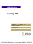
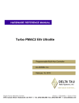
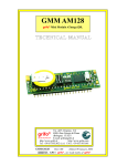
^1 USER MANUAL
PMAC 32-Bit Communication Driver
^3 Installing 32-Bit Driver for PMAC
^4 3xx-W32DRV-xUxx
^5 April 14, 2005
Single Source Machine Control
Power // Flexibility // Ease of Use
21314 Lassen Street Chatsworth, CA 91311 // Tel. (818) 998-2095 Fax. (818) 998-7807 // www.deltatau.com
Copyright Information
© 2004 Delta Tau Data Systems, Inc. All rights reserved.
This document is furnished for the customers of Delta Tau Data Systems, Inc. Other uses are
unauthorized without written permission of Delta Tau Data Systems, Inc. Information contained
in this manual may be updated from time-to-time due to product improvements, etc., and may not
conform in every respect to former issues.
To report errors or inconsistencies, call or email:
Delta Tau Data Systems, Inc. Technical Support
Phone: (818) 717-5656
Fax: (818) 998-7807
Email: [email protected]
Website: http://www.deltatau.com
Operating Conditions
All Delta Tau Data Systems, Inc. motion controller products, accessories, and amplifiers contain
static sensitive components that can be damaged by incorrect handling. When installing or
handling Delta Tau Data Systems, Inc. products, avoid contact with highly insulated materials.
Only qualified personnel should be allowed to handle this equipment.
In the case of industrial applications, we expect our products to be protected from hazardous or
conductive materials and/or environments that could cause harm to the controller by damaging
components or causing electrical shorts. When our products are used in an industrial
environment, install them into an industrial electrical cabinet or industrial PC to protect them
from excessive or corrosive moisture, abnormal ambient temperatures, and conductive materials.
If Delta Tau Data Systems, Inc. products are exposed to hazardous or conductive materials and/or
environments, we cannot guarantee their operation.
PMAC 32-Bit Communication Driver User Manual
Table of Contents
INTRODUCTION ..............................................................................................................................................................1
A Global View of the Driver ............................................................................................................................................1
Supported Operating Systems ..........................................................................................................................................2
Hardware Requirements ...................................................................................................................................................2
APPLICATION INSTALLATION AND SETUP ...........................................................................................................3
Software Installation ........................................................................................................................................................3
Automatic Detection of Plug and Play Devices ...............................................................................................................3
Non-Plug and Play [ISA] Devices....................................................................................................................................4
Windows 2000/XP Installation Steps (Non-Plug and Play [ISA] Devices) .................................................................4
Non-Plug and Play [ETHERNET] Devices – Installation ...........................................................................................7
Installing [Serial] Devices in Windows Operating Systems ......................................................................................10
Computers without Built-in COM Ports: Installing USB to Serial COM Port [Plug and Play] ...............................11
Setting up COM Port in Pewin 32 Pro2 ....................................................................................................................11
FIRST TIME USER REGISTRATION .........................................................................................................................13
Insert a Pre-configured Ethernet Devices in Delta Tau Applications .......................................................................14
DPRAM, IP Address and Interrupt Configuration ....................................................................................................15
Ethernet Port Change IP Address..............................................................................................................................15
Serial Port Configuration ..........................................................................................................................................16
TROUBLESHOOTING THE DRIVER CONFIGURATION .....................................................................................17
Registry Issues under Windows 2000 and XP................................................................................................................17
Part I..........................................................................................................................................................................17
Part II ........................................................................................................................................................................17
Configure/Reconfigure Parameters ................................................................................................................................18
ISA PMACs: I/O Port Address, DPRAM and Interrupt Assignment..........................................................................18
PMAC PCI: I/O Port Address, DPRAM and Interrupt Assignment ..........................................................................20
PMAC USB Configuration.........................................................................................................................................20
DPRAM on PMAC USB.............................................................................................................................................20
Serial Port Communication .......................................................................................................................................20
Higher Baud Rate Considerations .............................................................................................................................21
USB to Serial Converter ............................................................................................................................................21
PCMCIA/PCI to Serial Adapters ...............................................................................................................................21
Ethernet Port Communication ...................................................................................................................................21
Ethernet RJ45 Connector...........................................................................................................................................21
Changing Mode of Communication between USB and Ethernet ...............................................................................22
Delta Tau Driver Benchmark Times ..............................................................................................................................23
FIRMWARE DOWNLOADS..........................................................................................................................................25
PMAC/PMAC2 Firmware Downloading Jumpers.........................................................................................................25
Firmware Download Supported Modes..........................................................................................................................26
Firmware Download Steps .............................................................................................................................................26
Table of Contents
i
PMAC 32-Bit Communication Driver User Manual
ii
Table of Contents
PMAC 32-Bit Communication Driver User Manual
INTRODUCTION
The PMAC 32-bit communication driver provides all channel of communication between the host computer
and PMAC controllers. All methods of communication to PMAC are included. All types of PMACs (Turbo
and non-Turbo) use this driver for communication to the host computer.
A Global View of the Driver
The driver can be used for Windows 2000/XP application development. The driver consists of following
sets of files:
• PcommServer.exe – A Server application, responsible for core communication and transferring the
Data between the host computer and PMAC controllers.
• PmacISA.SYS, PmacPCI.SYS, PmacUSB.SYS – Windows 2000/XP kernel drivers.
• PmacISA.INF, PmacPCI.INF or PmacUSB.INF – Windows Setup Information files.
• ETHConfigure.EXE, ETH2Configure.EXE, USBConfigure.EXE, USB2Configure.EXE and
USBETHConfigure.EXE – Ethernet and USB configuration applications are responsible for boot
firmware download and the IP configuration application is responsible for USB and Ethernet modes
of communication. Furthermore, PmacETH.SYS loads the Ethernet mode at startup.
• A complete Source Code along with a simple User Interface for Linux operating system is packed in
the file pmac.0.0.1.tar.gz.
The illustration below shows how these modules are related.
Interface Programs
Delta Tau Driver
COM Interface
IPmacNC
Serial Com
COM Interface
IPmacDevice
PcommServer.exe
Contains communications and NC
code. Uses threads to buffer serial
busses, rotary buffer, memory
updating and Ethernet sockets.
Contains all global memory .
Exported DLL
Communication
Functions.
Pcomm32W.dll
A wrapper for the IPmacDevice
Interface for legacy programs.
W.DLL
A wrapper for the IPmacDevice
Interface for legacy programs.
Ethernet
COM(#)
System Function(s).
PmacServer uses this for
SERIAL communications
WinSock2
System Function(s).
PmacServer uses this for
ETHERNET
communicaations
IOCTL
Hardware Drivers
PmacUSB.sys
USB Hardware
PmacPCI.sys
PCI Hardware
PmacISA.sys
ISA Hardware
PmacETH.sys
ETH Configure
Introduction
1
PMAC 32-Bit Communication Driver User Manual
Supported Operating Systems
The following operating systems are supported:
• Windows 2000
• Windows XP
Hardware Requirements
The PMAC 32-Bit Communication Driver for Windows requires a minimum specification of hardware
for reliable operation and acceptable performance. These requirements include:
• 500 MHz Pentium III and above (of course, a faster computer will yield better throughput.)
• At least 20 MB of free disk space and 64 MB of RAM (PRO Suite2 requires a minimum of 50 MB of
free disk space.)
• A free serial communications port, USB port, Ethernet port, PCI BUS slot, or ISA BUS slot to talk to
PMAC for on-line processing
• Any monitor with SVGA resolution (800x600 with at least 256 colors)
2
Introduction
PMAC 32-Bit Communication Driver User Manual
APPLICATION INSTALLATION AND SETUP
This is a generic procedure for installing and setting up the application and driver for all Delta Tau
products. This procedure is applicable for all Delta Tau software packages.
Software Installation
1. Uninstall all old Delta Tau software applications including Pewin 32 Pro, PmacPlotPro, NCUI32,
PComm 32 Pro, Ptalk DT Pro and the setup programs (P1Setup32Pro, P2Setup32Pro and
TurboSetup32Pro and other programs based on Pcomm32Pro or Ptalk DT Pro) before beginning the
new Driver based applications.
2. Install Pro Suite2, or NCUI32 (versions 4.0 or 5.0). A setup application is provided on a CD-ROM or
floppy disk with the Setup.EXE application. Follow the steps provided by the setup application.
3. Restart the computer.
Automatic Detection of Plug and Play Devices
1. Perform the steps outlined in the Software Installation section.
USB and PCI Plug and Play devices are configured automatically at boot time. In addition, the USB
communications port is configured automatically whenever it is plugged in.
•
•
•
Note:
USB devices are listed in the Universal Serial Bus Controllers class while ISA and
PCI devices are listed in the Motion Class in the device manager as shown in the
screen below.
USB PMAC can be plugged in at any time once the computer has been restarted
after the ProSuite2 installation.
Serial and Ethernet devices are not listed in any category. No device drivers are
required to communicate to PMAC over serial or Ethernet modes. Follow the
instructions for the Ethernet configuration as outlined in the Non-Plug and Play
(Ethernet) devices section of this manual.
2. Restart the computer.
3. The computer will recognize and configure the new hardware. If prompted, give the path of driver
files. Depending on the operating systems, these files are in the following folders by default:
Windows XP:
c:\windows\system32\drivers
Windows 2000: c:\winnt\system32\drivers
Application Installation and Setup
3
PMAC 32-Bit Communication Driver User Manual
4. Proceed to the First Time User Registration section of this manual.
a)
b)
Note:
For Plug and Play devices, the I/O port, DPRAM base address, and Interrupt
are assigned by the operating system. There is not an option to change or
disable these parameters. However, the parameters assigned by the operating
system can be reviewed in the Resources page of the Windows© device
manager as shown in the screen below.
From the latest driver, the interrupts can be enabled or disabled from the
properties option of the PmacSelect() function. Proceed to the First Time
User Registration section of this manual for details.
Non-Plug and Play [ISA] Devices
Non-plug and play (ISA) devices are configured through the standard Add or Remove New Hardware
wizard. The next section describes all the necessary steps involved in configuring Delta Tau devices
under Windows 2000 or XP.
Windows 2000/XP Installation Steps (Non-Plug and Play [ISA] Devices)
1. Perform the first three steps outlined in the Software Installation section of this manual.
2. Select Add/Remove New Hardware from the Control Panel.
4
Application Installation and Setup
PMAC 32-Bit Communication Driver User Manual
3. From the Choose a Hardware Task window, select Add/Troubleshoot a Device.
4. From the Choose a Hardware Device window, select Add a New Device.
5. From the Find New Hardware window, select No to auto-detect options and continue.
Application Installation and Setup
5
PMAC 32-Bit Communication Driver User Manual
6. From the Hardware Type window, select Other devices . (This is done for the first installation only.)
Once the operating system’s device database is updated, all motion controllers will be listed in the
hardware types list. Use this for future PMAC hardware device additions.
7. Once the device database is compiled, Delta Tau Data Systems, Inc. will be added to the
manufacturers list. Scroll through the manufacturers list and select Delta Tau Data Systems, Inc.
8. Select the model from the available list (PMAC ISA Motion Controller). Windows 2000/XP allows
resource configuration during installation. Therefore, at this stage, base address, DPRAM
configuration and/or IRQ assignments can be configured.
The following table gives details of all configurations. By default, the basic configuration 0 is
selected.
Configuration Number
Basic Configuration 0
Basic Configuration 1
Basic Configuration 2
Basic Configuration 3
Basic Configuration 4
Basic Configuration 5
6
Modes of Communication
Communication through host port only
Communication through host port with DPRAM (regular size) enabled
Communication through host port with DPRAM (regular size) and
interrupts enabled
Communication through host port with interrupts enabled
Communication through host port with DPRAM (large size) enabled
Communication through host port with DPRAM (large size) and
interrupts enabled
Application Installation and Setup
PMAC 32-Bit Communication Driver User Manual
9. Select the appropriate configuration and after highlighting the resource, click on Change Setting to
set the values.
10. Select the driver file PMACISA.SYS. Browse to the correct folder. For Windows 2000, it is located
in C:\WINNT\System32\Drivers and for Windows XP, it is located in C:\Windows\System32\Drivers
folder.
11. Finish the installation and restart the computer. Review and reconfigure the resources before
restarting the computer. Furthermore, these resources can be changed at any time by launching the
Device Manager and the Add/Remove Hardware Wizard and clicking Resources.
12. Proceed to the First Time User Registration section of this manual.
Non-Plug and Play [ETHERNET] Devices – Installation
Configure the Ethernet devices by launching the ETHConfigure.EXE, ETH2Configure.EXE or
USBETHConfigure.EXE for 10 Base-T and 100 Base-T applications, respectively. Delta Tau provides
these files as part of the ProSuite2 or any other Delta Tau standard installations. Installation and
configuration of Ethernet devices is independent of the operating system.
Application Installation and Setup
7
PMAC 32-Bit Communication Driver User Manual
A network card must be configured on the computer with the PMAC connection before proceeding.
Furthermore, a crossover Ethernet cable or a private hub along with two straight cables is required for this
setup.
1. Perform the steps outlined in the Software Installation section of this manual.
2. From the control panel, select the properties of the network card that will communicate to the PMAC
via the Ethernet. Highlight the Internet Protocol (TCPIP) and select Properties.
3.
Type the private area IP address (e.g. 192.6.94.2) for this card and enter the subnet mask
(255.255.255.0) in the provided spaces. Close the properties page and restart the computer. The
Ethernet card configuration on the computer is now complete.
4. To configure the PMAC side, run the ETHConfigure.EXE(10 Base-T), ETH2Configure.EXE (100
Base-T), or USBETHConfigure.EXE (USB+100 Base-T) from programs\ Delta Tau\Pro Suite2\Delta
Tau Common\ program group. These applications are provided as part of the standard installation
and are placed in the c:\Program files\Delta Tau\Common\ folder. Proceed to the main screen by
clicking OK.
8
Application Installation and Setup
PMAC 32-Bit Communication Driver User Manual
The following setup screen will appear:
5. Select the appropriate settings from the following:
a. Enter the IP address (e.g. 192.6.94.5) in the Store IP row. Make sure that this address is in the
same subnet as the IP address in the PC NIC card. The last entry must be different from the one
in the PC (Ethernet Card).
b. Select the correct protocol between (UDP and TCP). Delta Tau recommends only TCP mode for
all Ethernet communications.
c. Select the correct hardware type.
d. Click the Store IP button.
6. Click Yes to store the IP address in the registry. Close the main screen. The Ethernet PMAC has
been added to the device list.
7. The new boards support both USB and Ethernet mode of communication and do not require a change
of firmware. A special firmware file and USB cable is required (not provided with standard
installation). Contact Technical Support to change the mode of communication. For detailed
instructions on how to switch the communication mode between USB and Ethernet on an ACC-54E
board or any other PMAC supporting Ethernet and USB mode, read the ACC-54E Users manual.
8. Similar to Ethernet Configuration utility, a USB configuration utility is also provided with any
standard installation. The USB configuration utility configures the communication card for USB
provided that the correct hardware type and serial number are selected.
Application Installation and Setup
9
PMAC 32-Bit Communication Driver User Manual
9. Proceed to the First Time User Registration section of this manual.
Installing [Serial] Devices in Windows Operating Systems
Configure the Serial Device to accept a Delta Tau product and identify which COM port each product is
connected to (PMAC, UMAC etc.).
1. Open the Device Manager in the Control Panel. Go to Ports (COM&LPT) and highlight the port
being configured.
2. Right click and select Properties.
3. Click on the Port Settings tab and verify that the settings are as follows:
• Bits per Second: 38400 (default)
• Data Bit: 8 (default)
• Parity: None (default)
• Stop bits: 1 (default)
• Flow Control: None (default)
10
Application Installation and Setup
PMAC 32-Bit Communication Driver User Manual
Computers without Built-in COM Ports: Installing USB to Serial COM Port
[Plug and Play]
After installing the USB to the serial device in Windows successfully, the newly added COM port
displays in the Device Manager (e.g., ATEN USB to serial cable [COM3]) with the new COM port
number.
Setting up COM Port in Pewin 32 Pro2
1. Open any of the Pro Suite 2 programs and select Setup from the Menu option.
2. From Pewin 32 Pro2, go to General Setup and Options and click the Select button and select Insert.
All available devices and COM numbers will display.
3. Select the COM port from the PMAC Devices dialog box. Click Test to verify communication with a
PMAC device.
Application Installation and Setup
11
PMAC 32-Bit Communication Driver User Manual
12
Application Installation and Setup
PMAC 32-Bit Communication Driver User Manual
FIRST TIME USER REGISTRATION
Once the device driver is installed, use the PmacSelect dialog to continue with additional configurations.
The PmacSelect dialog is accessible by all programs created with the driver (via the PmacSelect()
function). Launch the supplied Delta Tau applications (Pewin 32 Pro2, PmacTuningPro2 or other setup
programs) from the program menu and display the PmacSelect dialog.
1. From the PMAC Devices screen, select the device number and click Insert. The following window
listing all configured devices will appear:
2. Select the device to be configured and click OK.
3. Once a PMAC is listed in the PMAC Select window, it is registered. After a device is registered, it
should be tested. At this time, the following screen displays and the device is ready to use in any
application.
Troubleshooting the Configuration
13
PMAC 32-Bit Communication Driver User Manual
Note:
To add a previously configured Ethernet device, follow the instructions below.
Insert a Pre-configured Ethernet Devices in Delta Tau Applications
1. Connect the USB cable between the PMAC and the host computer.
2. Power cycle the PMAC unit.
3. Launch any Delta Tau application and select the PmacSelect() function.
4. Select any available (NA) device number and click Insert. The following window will appear.
5. Select any available (NA) device number and click Insert. The following window will appear.
6. Select the Ethernet radio button and click OK.
14
Troubleshooting the Configuration
PMAC 32-Bit Communication Driver User Manual
7. Enter the previously configured IP address and click OK. This will add an Ethernet device to the
registered device list.
Note:
a. The above procedure only adds a previously configured device in the host
computer’s registry. It does not reconfigure the PMAC device.
b. All PMACs with Ethernet port are pre-configured for Ethernet mode of
communication and the default IP address of 192.6.94.5.
c. The above procedure requires that the device is connected to the host computer
via a USB cable and visible in the Device Manager with no errors.
DPRAM, IP Address and Interrupt Configuration
The following window helps configure (enable, disable or change) the DPRAM automatic realtime/
background update functions, change the IP address and enable or disable the Interrupts for PMAC ISA
or PCI.
Ethernet Port Change IP Address
For Ethernet mode of communication along with DPRAM automatic update functions configuration, the
previously configured IP address can be viewed and changed. This requires a successful communation to
previously configured IP address through Ethernet cable. A power cycle to the PMAC/UMAC and
communication board is required to implement the IP address change. The Ethernet configuration utility
can also be used to set the Ethernet mode of communication or change the IP address.
Troubleshooting the Configuration
15
PMAC 32-Bit Communication Driver User Manual
Serial Port Configuration
Select the Properties option in the Serial Devices menu to set the port number, baud rate, timeouts,
handshake options and others such as odd/even parity checks.
16
Troubleshooting the Configuration
PMAC 32-Bit Communication Driver User Manual
TROUBLESHOOTING THE DRIVER CONFIGURATION
This section covers the issues of communication, firmware download and others related to changing the
card.
Registry Issues under Windows 2000 and XP
Part I
Give the appropriate group or user the right to load and unload device drivers in Windows XP (classic
view is required) or Windows 2000.
1. Log on to Windows with administrator rights.
2. Open the Start Menu, go to the Settings Menu Item, and then open the Control Panel.
3. Next open the Administrative Tools.
4. Next open the Local Security Policy.
5. From the Local Security Settings window, expand the Local Policies Tree.
6. Click the User Rights Assignment folder.
7. In the windowpane on the right side, double click the Load and Unload Device Drivers policy setting.
This will open the Local Security Policy Setting window.
8. Click the Add button in the dialog box and add whatever group or user that will have the capability to
load and unload the drivers (that is anyone who will run software that communicates to Delta Tau
Hardware).
Part II
Give the appropriate group or user the right to read and write to the HKEY_LOCAL_MACHINE/
System/CurrentControlSet/Services/PMAC key
1. From the Run menu, execute the program REGEDT32.EXE in Windows 2000 or REGEDIT.EXE in
Windows XP.
2. From the Windows pull-down menu in the registry editor, select HKEY_LOCAL_MACHINE. (This
step applies only to Windows 2000. Skip this step for XP.)
3. Expand the tree in the left panel to HKEY_LOCAL_MACHINE/System/CurrentControlSet/
Services/PMAC.
4. Highlight the PMAC key in the left panel.
5. Click the Security Menu item in the Registry Editor. Then select Permissions from the menu in
Windows 2000. In Windows XP, the Permission option is in the Edit menu.
6. The Permissions for the PMAC dialog box will display. From that window, click the Add button and
then select the group or user to run Delta Tau Software.
Note:
Under XP, if the Select Device from Pewin32PRO or the application cannot see a
COM port, locate the HKEY_LOCAL_MACHINE/Hardware/DeviceMap/
SerialComm key and give permission to all users to have full control over this key
and all entries in it.
Troubleshooting the Driver Configuration
17
PMAC 32-Bit Communication Driver User Manual
Configure/Reconfigure Parameters
Here are some of the issues that user may come across during launching a PMAC application where the
applications may fail to establish communication. The following items cover different modes of
communication individually.
ISA PMACs: I/O Port Address, DPRAM and Interrupt Assignment
The full configuration of all ISA PMACs can be viewed and modified from the Device Manager. A
yellow or a red sign next to the PMAC ISA controller means that either there is a conflict between the
parameters on PMAC and the host computer or DPRAM is not present while the card has been configured
to use DPRAM.
The properties page of the PMAC ISA will reveal the details of the parameters. Configure the port
address and add or remove DPRAM and interrupt according to the following table:
Configuration Number
Basic Configuration 0
Basic Configuration 1
Basic Configuration 2
Basic configuration 3
Basic Configuration 4
Basic Configuration 5
18
Modes of Communication
Communication through host port only
Communication through host port with DPRAM
(regular size) enabled
Communication through host port with DPRAM
(regular size) and interrupts enabled
Communication through host port with Interrupts
enabled
Communication through host port with DPRAM
(large size) enabled
Communication through host port with DPRAM
(large size) and interrupts enabled
Troubleshooting the Driver Configuration
PMAC 32-Bit Communication Driver User Manual
All ISA type PMACs are non-plug and play and therefore require manual configuration for I/O address,
DPRAM and Interrupt assignment. Match the port address to PMAC’s jumper settings (or switch settings
for PMAC2), map the DPRAM at an available space in the PC and assign an interrupt card. The
following window shows the details of the parameters of the troubled PMAC ISA device.
Available or unavailable parameters are listed in the Device Manager.
•
•
Important Note:
If an ISA PMAC is configured for DPRAM and after the firmware download
has been completed, power cycle the PMAC before the DPRAM can be used.
Large DPRAM (64Kbytes) is supported under ISA mode of communication.
However, under Microsoft operating systems, it is configured at even
addresses only and therefore only two ranges D0000-DFFFF and E0000EFFFF are supported for large DPRAM option.
Troubleshooting the Driver Configuration
19
PMAC 32-Bit Communication Driver User Manual
PMAC PCI: I/O Port Address, DPRAM and Interrupt Assignment
All PMAC PCIs are plug and play and therefore, are configured at boot time. For PMAC PCIs, the
interrupt is configured automatically. The driver works on the basis of shared interrupts. No steps are
required in configuring the interrupts. Similarly, if the option is present, DPRAM is configured and
mapped automatically.
Bootstrap mode is recognized automatically. The correct sequence for loading the device is to install the
driver first and then add the PMAC PCI. On the next boot, the device will be recognized and the driver
will be loaded by the operating system automatically.
If the PMAC PCI was added and then the software (driver) was installed later, once the driver files are
loaded, update the driver manually. The driver can be loaded easily by entering the right path for the
setup information file (PMACPCI.Inf) and the driver file (PMACPCI.SYS). These files are located in:
<WINDIR>\Inf and
<WINDIR>\System32\Drivers folders respectively.
where
<WINDIR> = c:\windows for Windows XP
<WINDIR> = c:\winnt for Windows 2000
The easiest way to reload a PMAC driver is to install the PC driver first. Then reinstall the hardware and
reboot the host computer.
PMAC USB Configuration
PMAC USB behaves similar to the PMAC PCI with one exception: PMAC USB can be plugged in and
out at any time. The device will be added to or removed from the Device Manager automatically.
Sometimes it is possible to unplug the USB device even if an application is communicating to it.
DPRAM on PMAC USB
•
•
•
•
For some of the old hardware, the USB communication boards had DPRAM present by default and
the DPRAM was available for automatic DPR functions. For those boards, the DPRAM was mapped
at $6C000 instead of $60000 (for ISA and PCI PMACs). I24 was used to determine the address of
the DPRAM on those PMACs. I24 would give the start address of the DPRAM ($6C000) to establish
communication.
For those boards, if the UMAC CPU has the onboard DPRAM option present, reinitialize with the E3
jumper and manually change the value of I24 to $6C000.
The latest generation of USB PMACs is available with and without DPRAM option configurations.
See the ACC-54E User manual for detailed information.
A universal method of determining the presence of DPRAM option is used. The two registers
X:$320f and X:$3210 determine the starting address as well as the length of the DPRAM if present.
The first register gives the starting address and the next register gives the end address. If the two
have different values, then the PDRAM is present with size equal to the difference of the two.
Otherwise, no DPRAM is present.
Serial Port Communication
Serial communication has its usual issues (baud rate, parity, and handshake signals). This driver requires
all of these settings to be correct for successful communication. Baud rate is the most essential of all.
• The driver will not function correctly if the baud rate on the serial port of the host computer is
different from the PMAC settings.
• Communicating via a Hyper-Terminal is a necessary but not sufficient test, in case there is a problem
in establishing the communication.
20
Troubleshooting the Driver Configuration
PMAC 32-Bit Communication Driver User Manual
•
Normal PMAC firmwares, with few exceptions, do not support parity. Furthermore, this driver uses
both RTS (enabled) and CTS (checked) handshake signals by default. However, it is possible to
change these settings. Once changed, the serial port may require a reset. Reboot the host computer to
ensure that the changes have taken effect.
Higher Baud Rate Considerations
To have a baud rate higher than 38400, the following table may be helpful:
PMAC CPU Speed
Supported Baud Rates
All PMACs
60 MHz, 90 MHz, 120 MHz, 150 MHz
9600, 19200, 38400 BPS
9600, 19200, 38400, 57600, 115200 BPS
Note:
Most PMACs support 76800 BPS. However, 76800 BPS is non-standard for most
PCs and Microsoft Windows and is not listed in the Com Port settings.
USB to Serial Converter
Starting with Windows Service Pack 2, most of the USB-to-Serial converters are supported. The driver
now supports the Microsoft serial driver.
PCMCIA/PCI to Serial Adapters
Similar to an USB-to-Serial converter, PCI-to-Serial converters can be used also, as long as the COM port
is created in the Device Manager.
Ethernet Port Communication
Ethernet communication does not involve any Ring 0 driver. The commands are directed from the DLL
directly to the Socket. Therefore, there is no Ethernet PMAC device listed in the Device Manager.
Follow the installation steps in the Ethernet Basic Configuration section. The following additional steps
can ensure reliable Ethernet communication:
1. Ping the Ethernet card from a command prompt.
2. For maximum speed, only the dedicated mode of communication is recommended.
Read the ACC-54E Revision 2 User manual for detailed information on the comparison of the two
protocols, their advantages and disadvantages.
Ethernet RJ45 Connector
This connector is used for Ethernet communications from a UMAC to a PC. The PC must have a card
dedicated solely to the UMAC network. The appropriate Category 5 10/100-Base-T network cable that
mates to RJ45 can be purchased from any local computer store. The type of network cable to purchase
depends on the configuration of the host PC.
• When making a direct connection to a Host communication Ethernet card in a PC, a Category 5
networking crossover cable must be used. A standard Category 5 straight through networking cable
cannot be used in this scenario. See the left section of the diagram below.
• When using a connection to a network Hub or switch, the standard Category 5 straight through
networking cable must be used and not a crossover cable. See the right section of the diagram below.
Performance can be degraded seriously by the use of a hub or switch. Network hubs or the more
intelligent network switches have processors inside them, which can add delays of at least 15 msec to
UMAC communications.
Troubleshooting the Driver Configuration
21
PMAC 32-Bit Communication Driver User Manual
Changing Mode of Communication between USB and Ethernet
UMAC, CPCI and PC104 with both USB and Ethernet options present allow changing the mode of
communication between the two. Delta Tau Driver library and Pewin32PRO Suite come with two utility
programs: USBConfigure.EXE and EthConfigure.EXE. To activate these utilities:
1. Enter the IP configuration, serial number and part identification number.
2. Download the boot firmware.
Procedures involving these updates are:
USB Boot Firmware
1. Call Delta Tau Technical Support to get the latest boot firmware file.
2. Connect a USB cable from PMAC’s communication (USB) port to the computer’s USB port.
3. Turn on power to the PMAC board.
4. Launch USBConfigure.EXE from the Programs menu.
5. Click the Store F/W button.
6. Browse to get the path of the PmacUSBxxxFx.iic file. Click OK to start the download.
7. On completion, select the correct hardware type (e.g., ACC-54E, CPCI, QMAC and PC104).
8. Enter the serial number from the communication board in the box provided and click Store ID.
9. Click Done to close the application.
10. Power cycle the PMAC and the communication board to complete the process.
Ethernet Boot Firmware
1. Call Delta Tau Technical Support to get the latest boot firmware file.
2. Connect a USB cable from PMAC’s communication (USB) port to the computer’s USB port.
3. Turn on power to the PMAC board.
4. Launch ETHConfigure.EXE from the Programs menu.
5. Click the Store F/W button.
6. Browse to get the path of the PmacETHxxxFx.iic file. Click OK to start the download.
7. On completion, select the correct hardware type (e.g., ACC-54E, CPCI, QMAC and PC104).
8. Enter the IP address in the address box and select the mode (either UDP – dedicated network or TCP
– on the same subnet).
9. Click Done to close the application.
10. Remove the USB cable and power cycle the PMAC and the communication board to complete the
process.
22
Troubleshooting the Driver Configuration
PMAC 32-Bit Communication Driver User Manual
Delta Tau Driver Benchmark Times
The following table provides detailed benchmark times for the driver.
Communication
Mode
GetResponse
Upload
8192 I-Variables
Download
8192 I-Variables
SetMem 8Kbyes
GetMem 8Kbytes
ISA
PCI
USB
Ethernet
Serial
Turbo PMAC
80 MHz
Port
DPR
ASCII
0.240
0.340
ms
ms
Turbo PMAC
80 MHz
Port
DPR
ASCII
0.170
0.200
ms
ms
(2.0)
(100 base-T)
Port only
Port only
38400
BPS
Port only
1.8 ms
1.4 ms
450 ms
400 ms
550 ms
640 ms
5 ms
(2.30 ms
115 K)
5.4 sec
1.2 sec
1.1 sec
2.4 sec
3.0 sec
30 sec
18 ms
15 ms
11 ms
8 ms
167 ms
125 ms
200 ms
190 ms
N/A
N/A
Troubleshooting the Driver Configuration
23
PMAC 32-Bit Communication Driver User Manual
24
Troubleshooting the Driver Configuration
PMAC 32-Bit Communication Driver User Manual
FIRMWARE DOWNLOADS
This section describes the step-by-step procedure used to update or change the firmware for any PMAC
with flash memory (PMAC1, PMAC2, Ultralite, Turbo PMAC1, Turbo PMAC2, Turbo Ultralite, and
UMAC). All of the information in this document assumes that the user has a legal copy of the firmware
for the PMAC. If the user has any questions about uploading firmware, contact Delta Tau Data Systems,
Inc.
To change the firmware, place the card into bootstrap mode by powering up the controller with the
bootstrap jumper in place. The bootstrap jumpers are listed in the table in this section.
Use caution when changing firmware because all information will be erased from the PMAC memory
before the firmware is downloaded. Make sure there are complete backup files for the application prior to
downloading the new firmware file.
Note:
If downloading firmware via serial port communications, set the baud rate to
38400 regardless of the setting of the baud rate jumpers.
PMAC/PMAC2 Firmware Downloading Jumpers
Type
PC/VME/STD
PC/VME/STD
PC/VME
PC/VME
Lite
Lite
Lite
Mini
CPU/Memory
3
Battery backed
4
Flash only
5
Universal
6
Turbo
3
Battery backed
4
Flash only
5
Universal
5
Universal
Type
CPU/Memory
PC/VME
PC/VME
PC/VME
Lite
Lite
Mini
VME Ultralite
PC Ultralite
PC Ultralite
UMAC
Flash only
5
Universal
6
Turbo
4
Flash only
5
Universal
5
Universal
4
Flash only
5
Universal
6
Turbo
6
Turbo
Type
CPU/Memory
P1 -PC/VME
P2 -PC/VME
Mini
PC Ultralite
VME Ultralite
4
4
Flash only
4
Flash only
Firmware Downloads
PMAC1
Part Number
Re-Initialization
Bootstrap
602 271/ 272/ 273/ 398-10x**
602 401/ 403/ 405-10x**
602 705-10x**
602866-10x**
602399-10x
602402-100/1/2
602402-103+
602812-10x
E51
E51 <CTRL-R>
E51
E51
E51
E51 <CTRL-R>
E51
E51
Replace chip
E51 <CTRL-O>
E4 (CPU)
E7
Replace chip
E51 <CTRL-O>
E106 (2-3)
E104
PMAC2
Part Number
Re-Initialization
Bootstrap
602 401/ 403/ 405-10x**
602 705-10x**
602866-10x**
602406-100
602406-101+
602405-10x
602643-10x
602415-10x
602182-182
603382-10x
E3 <CTRL-R>
E3
E3
E3 <CTRL-R>
E3
E3
E3 <CTRL-R>
E3
E3
E3
E3 <CTRL-O>
E4 (CPU)
E7
E3 <CTRL-O>
E0 (2-3)
E0 (2-3)
E3 <CTRL-O>
E0
E23
E23
Flex CPU PMAC1/PMAC2
Part Number
Re-Initialization
603605-10x
603605-10x
E51
E3
Bootstrap
E7
E7
25
PMAC 32-Bit Communication Driver User Manual
1
Re-Initialization: This copies the factory default values of I-variables, conversion table settings, and
VME and DPRAM address settings from the firmware EPROM into active memory.
2
Bootstrap: PMAC enters a special re-initialization mode that permits the downloading of new firmware
on flash only CPUs. PMAC can communicate over the PC/STD bus port or over the serial port at a baud
rate of 38,400, regardless of the setting of the baud rate jumpers.
3
Battery-Backed CPU: There are EPROMs for the firmware, EEPROM for the basic variables (most Ivariables, conversion table settings, and VME and DPRAM address settings), and battery-backed RAM
for the rest of the I-variables, programs, definitions, buffers, and tables.
4
Flash Only CPU: This has segmented flash EEPROM that consists of two sections: one holds the
firmware and the second holds all the user settings. To bypass the firmware download procedure, send
<CTRL-R>.
5
Universal CPU: This is a CPU that can be built as a battery-backed or flash only CPU.
6
Turbo CPU: This is similar to the flash only CPU.
** CPU piggyback board
Firmware Download Supported Modes
Starting with PRO Suite 2.0, all modes of communication support firmware downloads provided that a
host port communication is available. For UMAC via USB and Ethernet, ACC-54E Revision 102 or
above is required.
Firmware Download Steps
1. Apply the bootstrap jumper as described in the previous table.
2. From Pewin32PRO menu, go to the Setup menu and select General Setup and Options.
3. Select the appropriate device and then click on the Test button.
26
Firmware Downloads
PMAC 32-Bit Communication Driver User Manual
4. The controller is now in bootstrap mode. Click the OK button. If Cancel is clicked, the system will
issue a CTRL^R and restore normal operation to the PMAC.
Important Note:
If a PMAC ISA is configured for DPRAM, power cycle the PMAC before the
DPRAM is used after firmware download is complete.
5. The program will then ask for a bin file which is actually the firmware binary file. The firmware file
(not provided with any installation) is required and can be purchased as an Delta Tau Option (OPT10). For this example, the file is for a UMAC (Turbo PMAC2 type) and is called TURBO2.BIN.
Once purchased, store the binary file in any directory. After the file is selected, click the Open
button.
6. The program will then ask for initiation of the download. Click the Begin button.
Firmware Downloads
27
PMAC 32-Bit Communication Driver User Manual
7. When the download file is complete, the following screen displays. There is a 5-second delay before
the Done button is available. Click the Done button.
8. The program will then establish communications with the PMAC and the following window displays.
9. Power down the system and remove the bootstrap jumper. Then restart the controller with the new
firmware.
28
Firmware Downloads