1
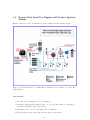
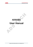
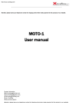
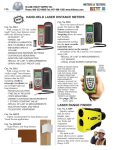
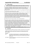
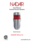
RADIANT PLASMA 4700
Plasma Spark Generator
Installation Guide /
User Manual
A SPARK OF FRESH AIR
Aquapulser.com
Contents
1 Introduction
1.1 About the Product . . . . . . . .
1.1.1 Product Specification . .
1.1.2 Product Description . . .
1.2 Components Required for Plasma
1.3 Warnings and Precautions . . . .
.
.
.
.
.
2
2
3
3
3
4
2 Modes of Operation
2.1 Inline Mode . . . . . . . . . . . . . . . . . . . . . . . . . . . . . . . . . . . . . . . .
2.2 Bypass Mode . . . . . . . . . . . . . . . . . . . . . . . . . . . . . . . . . . . . . . .
5
5
6
3 Installation Instructions
3.1 Single Cylinder Engine Install . . . . . . . . . . . . . . . . . . . . . . . . . . . . . .
3.2 Inline Mode Install for Vehicles with Ingition Coil Output Less Than 30kV HVDC
and Distributor . . . . . . . . . . . . . . . . . . . . . . . . . . . . . . . . . . . . . .
3.3 Bypass Mode Install for Engines with Ignition Coil output exceeding 30kV and
Distributor . . . . . . . . . . . . . . . . . . . . . . . . . . . . . . . . . . . . . . . .
3.4 Bypass Mode Install for Engines with Positive Ignition System . . . . . . . . . . .
7
7
9
11
4 Troubleshooting and FAQs
4.1 Troubleshooting . . . . . . . . . . . . . . . . . . . . . . . . . . . . . . . . . . .
4.2 FAQs . . . . . . . . . . . . . . . . . . . . . . . . . . . . . . . . . . . . . . . .
4.2.1 How to test if my RPG 4700 unit is working? . . . . . . . . . . . . . .
4.2.2 How to test the HV Polarity of an Ignition Coil? . . . . . . . . . . .
4.2.3 How to test the HV Polarity of an Ignition Coil without using Diodes?
4.2.4 How do I Reverse the Output Voltage Polarity of an Ignition Coil? . .
14
14
14
14
15
16
16
. . . . . . . . .
. . . . . . . . .
. . . . . . . . .
Spark Ignition
. . . . . . . . .
1
.
.
.
.
.
.
.
.
.
.
.
.
.
.
.
.
.
.
.
.
.
.
.
.
.
.
.
.
.
.
.
.
.
.
.
.
.
.
.
.
.
.
.
.
.
.
.
.
.
.
.
.
.
.
.
.
.
.
.
.
.
.
.
.
.
.
.
.
.
.
.
.
.
.
.
.
.
.
.
.
.
.
.
.
.
.
.
.
.
.
.
.
.
.
.
.
.
.
.
.
.
.
.
.
.
.
.
.
7
Chapter 1
Introduction
To ensure maximum performance and safety, please follow this manual.Please retain the manual for future reference after installation.
1.1
About the Product
The Radiant Plasma Generator 4700 is a high energy output, low power input plasma ignition
capacitor charger by Aquapulser. The RPG 4700 is an add-on Plasma spark device that will
convert any standard low energy ignition spark to a high energy plasma spark. The RPG 4700
2
requires a Negative high voltage low current DC pulse from an ignition coil or equivalent source
to generate a high energy plasma spark.
1.1.1
Product Specification
• Power input — 12 VDC, 3 amps max RMS, 9 amp surge (depending on supply)
• Internal capacitor rating — 450 VDC 4.7UF
• Internal HV protection — 30kV in Inline Mode. For higher voltages use bypass mode with
external diodes with good surge current rating as well as good heat dissipation characteristics.
• Max Plasma discharge Rate — 200 Hz (12000 RPM)
• Energy output — 424.469 mJ
• Safety circuit — Built in safety automatically detects no load condition and drains capacitor
in less than 2 seconds.
• HV Encapsulated
• Maximum Power —
30 watts
• RMS Current consumption at Max discharge rate — 2.5 amps
• Maximum Charging Voltage — -420V
1.1.2
Product Description
The RPG 4700 is a high energy output, low power input, integrated low noise high voltage capacitor
charger that is designed to operate at full output at charge discharge cycles exceeding 200Hz or
12,000 RPM. The RPG 4700 uses a custom high frequency transformer designed to rapidly charge
a 450 volt 4.7uF Polypropylene Film capacitor. The built in safety features of the RPG 4700
automatically drains the capacitor in less than 2 seconds, allowing safe handling when input
power is disconnected. With a wide input range from 5 to 14 volts the RPG 4700 can operate
from any DC power supply making it ideal for automotive and other portable outdoor high energy
plasma ignition applications. The optimal recommended power supply voltage is 12-18 VDC.
1.2
Components Required for Plasma Spark Ignition
• Negative DC High Voltage Source: Ignition Coil driven by magneto action, PWM
driver, or CDI based Ignition coil driver. Most if not all ignition systems in existence are
negative HV devices.
• Spark plug (Non Resistor) or Spark Gap 1 For installation on vehicles we recommend
high quality non resistor spark plugs especially made for High energy Ignition systems used
in Racing.
• Low impedance Plug Wires: Low resistance, Low impedance 7 - 8 mm copper core wires.
Please do not use any spiral, resistive or inductive cables with moderate or high impedance.
Non resistor plugs and low impedance cables are critical for the plasma spark event. Without
these parts, the RPG 4700 will not generate plasma spark discharge.
1 Standard spark plug gaps will work. Increasing the gap improves the transfer of energy from the spark to the
surrounding combustible fuel charge. But restrict the gap to 5mm (0.5cm) at the most, as higher gaps increase the
risks of internal arcing (in Inline Mode) and will drastically reduce the longevity of the unit.
3
Figure 1.1: Adjustable Tungsten Spark Gap
• 10 amp external fuse: As with all automotive electronics, this unit when wired inside a
vehicle must be wired through the fusebox with a separate 10A fuse which will protect both
the unit and the vehicle from surges greater than 10 amps.
• Silicone Grease: When connecting the RPG using spark plug cables and boot connectors,
make sure the insulated grips of the HV input plug terminal and Plasma output Plug terminal
are coated with silicone grease, for lubrication and easy removal of plug connectors and to
prevent HV corona arc formation.
1.3
Warnings and Precautions
• The RPG 4700 is designed to operate on NEGATIVE HV DC pulses from standard ignition
coils. The unit has not been tested in conjunction with MSD devices. It should perform
provided the output polarity of any Multiple Discharge Ignition device is negative HVDC
and the frequency does not exceed 300Hz max.
• If you are using the RPG 4700 to power tesla coils or large copper bus bars, please keep the
unit as far away from the primary discharge coil and spark gap as possible. Use extended
copper core ignition cables for the plasma output lead. Discharging plasma into thick copper
bars or tesla coil primaries creates intense Electrostatic fields which may permanently damage
the charging microprocessor resulting in a DEAD UNIT. This unit is a research prototype
device and optimization for ESD is ongoing.
• The plasma generated by the RPG 4700 is extremely bright and emits UV light, please use
protective UV glasses and altogether refrain from observing the spark for long periods of
time.
• Do not use the RPG4700 across spark gaps greater than 5mm. Discharging plasma across
larger gaps increase the risk of internal arcing which could permanently damage the unit
4
• When connecting the RPG4700 to a DC power supply make sure the black lead is connected
to the negative and red wire is connected to positive. Do not switch the power input polarity.
5
Chapter 2
Modes of Operation
The RPG 4700 has two basic modes of operation, Inline and Bypass.
2.1
Inline Mode
Figure 2.1: Circuit schematic for Inline Mode setup. The RPG4700 goes inline with an existing
ignition system.
In Inline Mode the HV signal travels inline with the plasma discharge inside the unit meaning
the source (-) HV DC pulse from an ignition coil is connected to the HV input terminal of the
RPG 4700 and the plasma discharges into the inline HV signal inside the unit. The plasma output
connects to a tungsten spark gap or a spark plug. The High Voltage DC source from the ignition
coil has to be limited to 30 kV when operated in Inline mode. Inline mode is recommended for
HVDC pulse source less than or equal to 30kV.
6
2.2
Bypass Mode
Figure 2.2: Circuit schematic for Bypass Mode setup. The RPG4700 bypasses the existing ignition
system and is connected in parrallel to the spark plug.
In this mode the HV input terminal of the RPG 4700 is not used. The HV terminal is
insulated using a silicone spark plug boot connector. In bypass mode, the High Voltage input
from the ignition coil is bypassed from entering the unit and the unit only generates the necessary
discharge. The Plasma output is directly connected to the spark plug or spark gap. The HVDC
low energy source is also connected to the spark plug or spark gap. Bypass mode is a must when
plasma spark is desired with source HVDC greater than 30kV and also helps minimize EMI/RF
interference if any. When plasma output is desired across multiple spark plugs, each spark plug
must have a dedicated 15 kV or 20kV HV microwave oven blocking diode when connections are
made from the plasma output
7
Chapter 3
Installation Instructions
It is assumed that the user attempting any of the following installations is fairly well versed with
the general concept of plasma ignition and has read the introductory chapters of this manual.
3.1
Single Cylinder Engine Install
Engines of this type include portable generators, marine engines, outboard motors, motorbike
engines etc. Refer to Figure 2.1 for schematic.
You will need:
• Non-resistor type spark plug
• Low impedance copper core ignition cable
• Battery to power the RPG4700 unit
• 10A fuse
Steps:
1. Connect the HV ignition spark output of the portable generator / marine engine to the HV
input of the RPG 4700.
2. Connect the PLASMA OUTPUT to the portable generator / marine engine’s Non Resistor
Spark plug using a high voltage ignition low resistance copper core cable connector.
3. Connect the GROUND LEAD of the RPG 4700 to the Portable Generator / Marine Engine
ground (usually the metal chassis)
4. Connect the power supply cables of the RPG 4700 to 12 VDC source via a 10A fuse.
5. Start the portable generator / Marine Engine
6. Turn off the RPG 4700 before or immediately after shutting down the engine.
7. Disconnect RPG 4700 from its power supply when not in use
8
Figure 3.1: Circuit schematic for a multi-cylinder distributed inline install.
3.2
Inline Mode Install for Vehicles with Ingition Coil Output Less Than 30kV HVDC and Distributor
Engines of this type include most multi-cylinder cars with stock ignition systems and either a
rotary or transistorized distributor to distribute the HV spark to the various cylinders.
You will need:
• Non-resistor type spark plugs - one for each cylinder
• Low impedance copper core ignition cables - one for each cylinder plus one additional (eg.,
a 4 cylinder install wil require 5 such cables)
• Regular/stock/RF supression ignition cable
• Battery to power the RPG4700 unit
• 10A fuse
9
Steps:
1. Connect the HV ignition coil spark output of the vehicle to the HV INPUT male plug
connector of the RPG 4700 using the stock/regular resistive ignition cable
2. Connect the PLASMA OUTPUT of the RPG 4700 to the ROTOR input of the vehicles
IGNITION SPARK DISTRIBUTOR using the low impedance copper core cable.
3. Connect the distributor terminals to their respective plugs using the low impedance copper
core cables.
4. Connect the GROUND LEAD of the RPG 4700 to the Vehicle ground (usually the metal
chassis)
5. Connect the power supply cables of the RPG 4700 to the vehicles battery via a 10A fuse,
but ensure that power is supplied only when IGNITION KEY is turned ON. Power supply
to RPG 4700 should be cut off when the IGNITION KEY is in the off position.
6. DO NOT wire power input connections such that the unit is always ON. The unit must be
turned off when the motor is not in use. This is both for safety and proper functioning and
longevity of the unit.
7. Ensure that the RPG 4700 unit is mounted where it is relatively cool and not exposed to
excess heat from the engine. Disconnect RPG 4700 from its power supply when not in use
for prolonged periods
Notes
This method is not recommended as the plasma spark has to jump the rotor gap and the spark
plug reducing the amount of available energy for igniting the fuel. We highly recommend Bypass
method for optimal performance.
3.3
Bypass Mode Install for Engines with Ignition Coil output exceeding 30kV and Distributor
Engines of this type include most multi-cylinder cars with high performance ignition systems and
either a rotary or transistorized distributor to distribute the HV spark to the various cylinders.
You will need:
• Non-resistor type spark plugs - one for each cylinder
• Regular/stock/RF supression ignition cables - one for each cylinder plus one additional (eg.,
a 4 cylinder install wil require 5 such cables)
• HV insulated copper core wires - one for each cylinder plus one additional.
• HV Diodes with at least 15kV rating and surge rating of at least 50A.
• Battery to power the RPG4700 unit
• 10A fuse
10
Figure 3.2: Circuit schematic for a multi-cylinder distributed bypass install. Figure 3.5 shows the
details for preparing the wires for optimal install.
Steps:
1. Do not use the HV input terminal. Use a silicone boot connector to insulate the HV input
terminal of the RPG4700.
2. The plasma output must connect individually to each spark plug at the plug tip using
low impedance copper core HV insulated wire and ensure that each spark plug lead has a
dedicated 15 kV microwave oven diode in the right orientation. Refer to Figure 3.3.
3. Connect the plasma output directly to the spark plug using a 15 kV blocking diode for each
spark plug. The diodes should be oriented so that the positive end faces the spark plug while
the negative end connects to the RPG 4700 plasma output.
4. Connect all the individual leads from the negative (CATHODE) side of the diodes using a
wire nut or equivalent to the plasma output of the RPG 4700.
11
5. Connections may also be made at the distributor end instead of the spark plug end. This
will depend on the layout of your engine. IF connection is made at the distributor end use
only Copper Core, low resistance Racing cables.
6. The HVP 16 diodes may also be mounted on a board under the hood and plasma connections
can be made at the distributor end of the ignition cable rather than axially placing the diodes
along the cable as depicted above.
7. For making connections at the distributor end follow exactly the same crimping procedure
outlined above, but make sure the ignition cables are low resistance copper core cables
otherwise plasma spark will not occur.
8. The diodes may also be placed inside a plastic enclosure such as a ABS plastic project box.
9. Connect the GROUND LEAD of the RPG 4700 to the Vehicle ground (usually the metal
chassis)
10. Connect the power supply cables of the RPG 4700 to the vehicles battery via a 10A fuse,
but ensure that power is supplied only when IGNITION KEY is turned ON. Power supply
to RPG 4700 should be cut off when the IGNITION KEY is in the off position.
Figure 3.3: Wiring for bypass install. The yellow RF cable connects the distributor terminal to
the appropriate spark plug, while the red insulated copper wire connects the RPG4700 plasma
output to the spark plug. Note how the two wires are joined (soldered) inside the boot connector
at the spark plug end.
12
3.4
Bypass Mode Install for Engines with Positive Ignition
System
Engines of this type are rare and usually incorporate a highly customized ignition system.
Figure 3.4: Circuit schematic for a multi-cylinder distributed bypass install for a positive HV
ignition system.
You will need:
• Non-resistor type spark plugs - one for each cylinder
• Regular/stock/RF supression ignition cables - one for each cylinder plus one additional (eg.,
a 4 cylinder install wil require 5 such cables)
• HV insulated wires - one for each cylinder plus one additional.
• HV Diodes with at least 15kV rating and surge rating of at least 50A.
13
• Battery to power the RPG4700 unit
• 10A fuse
Steps:
1. The HV input terminal will not be required. Insulate the HV Input terminal connector of
the RPG 4700 using a spark plug boot connector
2. For POSITIVE HVDC connect a 30 kV Microwave oven diode bank using NTE 517 or
HVP16 diodes to the Plasma ground lead of the RPG 4700.
3. After the 30 kV diode bank has been connected to the plasma ground, the ground lead
should connect through 15 kV diodes to each individual spark plug connecting at the plug
tip.
4. Connect the Plasma output terminal of the RPG 4700 to the Chassis ground.
5. Connect the power supply cables of the RPG 4700 to the vehicles battery via a 10A fuse.
Figure 3.5: Steps to assemble wires for optimal bypass mode hookup. You will receive all the
items pictured in the images if you ordered the RPG4700 along with the self wiring kit
14
Chapter 4
Troubleshooting and FAQs
4.1
Troubleshooting
I have made all connections but there is no plasma event, only regular HV spark from
the ignition coil happens across spark plug / gap.
Make sure that RPG 4700 is connected to a 12VDC power supply. Make sure the 12VDC power
supply is active. Ensure that the plasma GROUND wire is connected to the Ground of the spark
plug.
Unit powers and draws 2 to 3 amps from 12 VDC supply on but there is no plasma
discharge, only regular HV spark from ignition coil.
Check if the 12 VDC power input polarity has been reversed. Ensure that positive and negative
of the 12VDC supply connects to the red and black power input leads of the RPG 4700.
Inline mode operation: The unit is powered on, however there is no plasma discharge
or normal HV discharge even though the ignition coil is firing normally.
Make sure the HV source is negative DC. Disconnect all the HV cable connectors and test if
the unit is working by measuring the charging voltage across the plasma output and ground of the
unit. If the RPG charges to 400 to 425 volts, the unit is working fine, however the internal 30 kV
diode bank needs to replaced. The unit will work in Bypass mode if internal diodes have failed,
but ensure up to 30 kV external diode protection is added.
4.2
4.2.1
FAQs
How to test if my RPG 4700 unit is working?
1. Remove all High voltage ignition cable connectors, there should be no connections to the
HV input or plasma output connectors.
2. Source a standard Multimeter that can read DC voltages upto 600 VDC or higher.
3. Connect the Red probe of the MULTIMETER to the plasma output connector tip
4. Connect the Black probe (COM) of the MULTIMETER to the Plasma Ground wire of the
RPG 4700
5. Make sure the MULTIMETER is set to read the DC voltage upto 600 Volts.
6. Connect the power supply to the RPG 4700 and turn the power supply on.
15
7. Once the RPG 4700 is powered on, The MULTIMETER should read a voltage from -400 to
-425 volts. Your unit is functioning normally. (416 421 volts is range tested while factory
setting)
8. As the unit outputs isolated negative DC voltage there may be a problem getting an accurate
reading with some multimeters displaying a fluctuating voltage from -300 to -450volts when
red probe is connected to Plasma output and Black probe (COM) to Plasma Ground lead.
9. To test the output voltage of the RPG 4700 unit connect the red probe of the multimeter to
the Plasma GND lead and the black probe to the Plasma output terminal. The multimeter
should read +400 to +425 volts. Your unit is functioning normally.
10. Do not short the probes or metallic parts of probes while the unit is powered on. Capacitor
high current impulse discharge will damage equipment and cause physical injury.
4.2.2
How to test the HV Polarity of an Ignition Coil?
Figure 4.1: Circuit schematic for testing ignition coil polarity using HV diode
The RPG 4700 is designed for use with ignition coils that output NEGATIVE HVDC. However
the unit can also be used with an ignition coil that outputs POSITIVE DC, but will require the
use of external diodes. See wiring diagrams at the end of the document.
1. In order to test for polarity of your Ignition coil, you will need a 40 to 80kV diode. Rather
than sourcing a single 40 to 80kV diode, 3 to 4 HVP16 diodes may be strung in series.
2. Connect the output of the ignition coil to the 80kV diode and then a spark gap in series to
ground.
16
3. Connect a spark gap tester bypassing the 80 kV diode as indicated in the diagram. The gap
width must be twice that of the spark plug.
4. If the Ignition coil were to output Negative HVDC then it will arc across the larger bypass
spark gap.
5. Reverse the 80kV diode to confirm Negative HVDC. Once the diode connections are reversed
the Negative VDC arc should happen across the spark plug and not the bypass gap.
4.2.3
How to test the HV Polarity of an Ignition Coil without using
Diodes?
In order to test for polarity of your Ignition coil, you will need to:
1. Connect a single spark plug wire from the distributor to the HV input terminal.
2. Connect the plasma output of the unit to the spark plug using a copper core low impedance
ignition cable. Make sure the spark plug is non-resistor.
3. Connect the Plasma GND lead to the chassis ground of the vehicle and make sure the spark
plug is also connected to the chassis ground of the engine.
4. Do not power the RPG unit yet. When the engine is idling and a regular spark is observed,
the ignition coil outputs Negative DC. Power the unit on and you should observe the plasma
effect.
5. If the Ignition coil were to output Positive HVDC then no spark event will happen, not even
the regular ignition spark will be observed as the HV DC pulse will flow to ground through
the internal blocking diodes of the RPG unit.
NOTE: This test may not be accurate If the internal 30kV diode bank comprising of 4 NTE
517 diodes fail for ex: discharging across gaps exceeding 0.5cm, then regardless of the polarity of
the coil, no spark event will occur as the HV from the coil will flow straight to ground through the
internal diode bank. However the unit will still work in bypass mode with an external diode bank.
4.2.4
How do I Reverse the Output Voltage Polarity of an Ignition Coil?
The easiest and simplest way to change the HVDC output voltage of the Ignition coil is to switch
the connection polarity of the ignition coil’s primary coil. Simply reverse the primary coil connections to change the polarity of the HVDC ignition coil output.
17