1
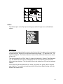
16-Channel
Color Multiplexer
Installation and Operating Instructions
MENU
GV-CMP 163R
ii
ISSUE 1 – AUGUST 2003
LIMITATION OF LIABILITY
THE INFORMATION IN THIS PUBLICATION IS BELIEVED TO BE ACCURATE IN ALL
RESPECTS, HOWEVER, WE CANNOT ASSUME RESPONSIBILITY FOR ANY
CONSEQUENCES RESULTING FROM THE USE THEREOF. THE INFORMATION
CONTAINED HEREIN IS SUBJECT TO CHANGE WITHOUT NOTICE. REVISIONS
OR NEW EDITIONS TO THIS PUBLICATION MAY BE ISSUED TO INCORPORATE
SUCH CHANGES
iii
WARNINGS AND CAUTIONS
TO REDUCE THE RISK OF FIRE OR ELECTRIC SHOCK, DO NOT EXPOSE THIS PRODUCT
TO RAIN OR MOISTURE. DO NOT INSERT ANY METALLIC OBJECTS THROUGH THE
VENTILATION GRILLS OR OTHER OPENINGS ON THE EQUIPMENT.
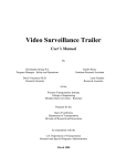
CAUTION
EXPLANATION OF GRAPHICAL SYMBOLS
The lightning flash with arrowhead symbol, within an equilateral triangle, is
intended to alert the user to the presence of uninsulated “dangerous voltage”
within the product’s enclosure that may be of sufficient magnitude to constitute a
risk of electric shock to persons.
The exclamation point within an equilateral triangle is intended to alert the user to
the presence of important operating and maintenance (servicing) instruction in
the literature accompanying the product.
iv
FCC COMPLIANCE STATEMENT
FCC INFORMATION : THIS EQUIPMENT HAS BEEN TESTED AND FOUND
TO COMPLY WITH THE LIMITS FOR A CLASS A DIGITAL DEVICE,
PURSUANT TO PART 15 OF THE FCC RULES. THESE LIMITS ARE
DESIGNED TO PROVIDE REASONABLE PROTECTION AGAINST HARMFUL
INTERFERENCE WHEN THE EQUIPMENT IS OPERATED IN A
COMMERCIAL ENVIRONMENT. THIS EQUIPMENT GENERATES, USES,
AND CAN RADIATE RADIO FREQUENCY ENERGY AND IF NOT INSTALLED
AND USED IN ACCORDANCE WITH THE INSTRUCTION MANUAL, MAY
CAUSE HARMFUL INTERFERENCE TO RADIO COMMUNICATIONS.
OPERATION OF THIS EQUIPMENT IN A RESIDENTIAL AREA IS LIKELY TO
CAUSE HARMFUL INTERFERENCE IN WHICH CASE THE USER WILL BE
REQUIRED TO CORRECT THE INTERFERENCE AT HIS OWN EXPENSE.
CAUTION : CHANGES OR MODIFICATIONS NOT EXPRESSLY APPROVED
BY THE PARTY RESPONSIBLE FOR COMPLIANCE COULD VOID THE
USER'S AUTHORITY TO OPERATE THE EQUIPMENT.
THIS CLASS A DIGITAL APPARATUS COMPLIES WITH CANADIAN ICES-003.
NORME NMB-003 DU CANADA.
CE COMPLIANCE STATEMENT
WARNING
This is a Class A product. In a domestic environment this product may cause
radio interference in which case the user may be required to take adequate
measures.
v
IMPORTANT SAFEGUARDS
1.
READ AND RETAIN INSTRUCTIONS
Read the instruction manual before operating the
equipment. Retain the manual for future reference.
2.
CLEANING
Turn the unit off and unplug from the power outlet
before cleaning. Use a damp cloth for cleaning. Do not
use harsh cleansers or aerosol cleaners.
3.
ATTACHMENTS
Do not use attachments unless recommended by
manufactured as they may affect the functionality of the
unit and result in the risk of fire, electric shock or injury.
4.
MOISTURE
Do not use equipment near water or other liquids.
5.
ACCESSORIES
Equipment should be installed in a safe, stable location.
Any wall or shelf mounting accessory equipment should
be installed using the manufacture’s instructions. Care
should be used when moving heavy equipment. Quick
stops, excessive force, and uneven surfaces may
cause the equipment to fall causing serious injury to
persons and objects.
10. LIGHTNING
For protection of the equipment during a lightning storm
or when it is left unattended and unused for long
periods of time, unplug the unit from the wall outlet.
Disconnect any antennas or cable systems that may be
connected to the equipment. This will prevent damage
to the equipment due to lightning or power-line surges.
11. OVERLOADING
Do not overload wall outlets and extension cords as this
can result in a risk of fire or electric shock.
12. SERVICING
Do not attempt to service the video monitor or
equipment yourself as opening or removing covers may
expose you to dangerous voltage or other hazards.
Refer all servicing to qualified service personnel.
13. DAMAGE REQUIRING SERVICE
Unplug the equipment from the wall outlet and refer
servicing to qualified service personnel under the
following conditions:
A.
B.
6.
7.
8.
VENTILATION
Openings in the equipment, if any, are provided for
ventilation to ensure reliable operation of the unit and to
protect if from overheating. These openings must not
be blocked or covered
POWER SOURCES
The equipment should be operated only from the type
of power source indicated on the marking label. If you
are not sure of the type of power supplied at the
installation location, contact your dealer. For
equipment designed to operate from battery power,
refer to the operating instructions.
GROUNDING OR POLARIZATION
Equipment that is powered through a polarized plug (a
plug with one blade wider than the other) will fit into the
power outlet only one way. This is a safety feature. If
you are unable to insert the plug fully into the outlet, try
reversing the plug. Do not defeat the safety purpose of
the polarized plug.
Alternate Warning: If the equipment is powered
through a three-way grounding-type plug, a plug having
a third (grounding) pin, the plug will only fit into a
grounding-type power outlet. This is a safety feature.
Do not defeat the safety purpose of the grounding-type
plug. If your outlet does not have the grounding plug
receptacle, contact your local electrician.
9.
vi
CORD AND CABLE PROTECTION
Route power cords and cables in a manner to protect
them from damage by being walked on or pinched by
items places upon or against them.
C.
D.
E.
F.
When the power supply cord or the plug has been
damaged.
If liquid has spilled or objects have fallen into the
unit.
If the equipment has been exposed to water or
other liquids.
If the equipment does not operate normally by
following the operating instructions, adjust only
those controls that are covered by the operating
instructions. Improper adjustment of other controls
may result in damage to the unit.
If the equipment has been dropped or the casing
damaged.
When the equipment exhibits a distinct change in
performance.
14. REPLACEMENT PARTS
When replacement parts are required, be sure the
service technician uses replacement parts specified by
the manufacturer or that have the same characteristics
as the original part. Unauthorized substitutions may
result in fire, electric shock, or other hazards.
15. SAFETY CHECK
Upon completion of any service or repairs to the
equipment, ask the service technician to perform safety
checks to verify that the equipment is in proper
operating condition.
16. FIELD INSTALLATION
The installation of equipment should be made by a
qualified service person and should conform to all local
codes.
TABLE OF CONTENTS
INTRODUCTION ....................................................................................................................... 1
Features.................................................................................................................................. 1
Technical Overview................................................................................................................. 1
INSTALLATION ......................................................................................................................... 2
System Configuration.............................................................................................................. 2
Camera Connections .............................................................................................................. 2
Adding Monitors ...................................................................................................................... 2
Connecting Recording Devices ............................................................................................... 3
Daisy–Chaining Equipment ..................................................................................................... 3
Accessing the TOP and BOTTOM Menus ............................................................................... 3
Top Menu............................................................................................................................ 3
Bottom Menu ...................................................................................................................... 4
Live ......................................................................................................................................... 4
Playback ................................................................................................................................. 4
Preview ................................................................................................................................... 4
Setup Menu............................................................................................................................. 5
Time Date Setup ................................................................................................................. 5
Camera Title Setup ............................................................................................................. 6
Camera Sequence Setup.................................................................................................... 7
Alarm Setup ........................................................................................................................ 8
Alarm History List...............................................................................................................11
Motion Detection Setup......................................................................................................11
VCR System Setup ............................................................................................................14
Camera Picture Adjustment ...............................................................................................15
Macro Setup ......................................................................................................................15
Unit Setup ..........................................................................................................................16
Password Setup.................................................................................................................17
PRODUCT OVERVIEW ............................................................................................................18
Front Panel Buttons ...............................................................................................................18
MENU SETUP AND OPERATION ............................................................................................21
POP–Up Menu .......................................................................................................................21
Live Camera Change .........................................................................................................21
VCR Camera Change ........................................................................................................21
Zoom .................................................................................................................................21
Full.....................................................................................................................................21
Panic Record .....................................................................................................................22
Freeze ...............................................................................................................................22
Sequence...........................................................................................................................22
Utilities ...............................................................................................................................23
APPENDIX A - TROUBLESHOOTING.....................................................................................27
APPENDIX B - REMOTE CONTROL OPERATION ..................................................................28
Remote Control for Daisychained Multiplexers...................................................................28
Remote Commands Set.....................................................................................................28
Functional remote Commands ...........................................................................................30
vii
Connector PIN Assignments ..............................................................................................31
APPENDIX C - FACTORY DEFAULT SETTINGS ...................................................................32
APPENDIX D - SPECIFICATIONS...........................................................................................34
viii
CHAPTER 1
INTRODUCTION
Features
•
•
•
•
•
•
•
•
•
•
•
•
•
•
Compatible with standard color cameras and other video sources
Able to decode tapes from many other brands of multiplexers
Multiple user-selectable formats for displaying camera images.
Multiple monitor outputs (1 Main, 1 Auxiliary) allow simultaneous multi-camera and fullscreen viewing.
On-screen display includes date, time, alarm status, video loss, camera number, and 24character camera titles.
Programmable day and night motion-detection schedules.
Each camera has a programmable 256-target (16 x 16) motion-detection grid.
Nonvolatile program memory saves all user settings and protects them against power
outages.
One TTL/CMOS contact closure alarm for each camera.
Alarm input polarity is user selectable.
VCR switch pulse input for synchronization with VCRs having switch pulse feature.
Full triplex operation allows simultaneous recording, playback, and live viewing.
256-event alarm history log.
Linear zoom IN and OUT up to 32 times.
Technical Overview
The Triplex Multiplexers feature motion detection and multi-lingual setup menus.
The multiplexer contain BNC input and output for VCR connection. The main monitor connect
to a composite BNC output. This BNC auxiliary output to be used for “spot” monitor or as
sources of video for other devices.
The multiplexer has a large selection of user selectable display formats. It also has digital
zooming up to 32 times the original scene.
A multi-lingual menu allows for easy setup. The user’s configuration is stored in nonvolatile
memory to protect against loss of settings during power outages.
The multiplexer plays back video tapes recorded with many other multiplexers. These include
but are not limited to: Dedicated Micros, Robot, Kalatel, and Pelco. Multiplexers can be “daisy
chained” and addressed and controlled by a single control panel. The multiplexer can also be
addressed by a computer using either an RS-232 or RS-485 connection.
1
CHAPTER 2
INSTALLATION
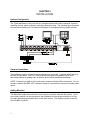
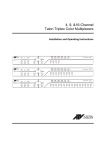
System Configuration
The Triplex Multiplexer is only one part of a complete system that controls cameras, monitors,
recording devices, alarm equipment, and other accessory items. The following figure illustrates
the connections feeding off a 16-channel multiplexer for a complete security system solution.
Camera Connections
The multiplexer support 16 camera inputs depending on the model. Cameras attach directly to
the BNC IN connectors. BNC OUT connections provide loop-out capability with an autoterminating feature for looping video to another device without additional termination.
NOTE: Connecting a cable to the loop-through connector switches off the termination. Do not
connect a cable to the BNC OUT connection unless it is connected to the input of another video
device.
Adding Monitors
The MAIN BNC output connections are for the primary monitors used with the system. Up to
one auxiliary monitor can be connected to the multiplexer for use as spot monitors or to view
live video while playing recorded video on the main monitor. The auxiliary monitor connect to
the AUX BNC connector.
2
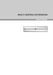
Connecting Recording Devices
The multiplexer have BNC connection for use with a recording device such as a VCR or DVR
(Digital Video Recorder). The figures below show examples of one VCR connected to the
multiplexer for use in both recording and playback, and two VCRs being used to allow
simultaneous recording and viewing of video.
Connection to a Single Recording Device
Using multiple Recording Devices
Daisy–Chaining Equipment
The multiplexer can be daisy-chained to other multiplexers.
Accessing the TOP and BOTTOM Menus
The multiplexers use On-Screen Display (OSD) menus. Navigation through the menus is
possible through the front panel buttons or through a remote control device.
There are two main menus: Top and Bottom. The Top Menu is accessed by moving the cursor
to the top edge of the screen. The Bottom Menu is accessed by moving the cursor to the
bottom edge of the screen.
Top Menu
The Top Menu has five options:
3
Live
Selecting Live returns the unit to the last Live mode screen format displayed.
Playback
The Playback option returns the unit to the last screen format accessed in the
Playback mode.
Preview
Selecting the Preview options displays a preview of recorded video.
Setup
The Setup option provides access to the Setup menu. This feature is
password protected. The options in the Setup menu are described in detail in
the following section.
Cancel
The Cancel button exits the Top Menu without any changes.
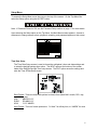
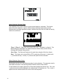
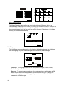
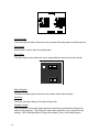
Bottom Menu
The Bottom Menu is only available in the Live Mode. The options available depend on the
model of the multiplexer. The menu shown above lists all the options available on the 16channel model.
Full
Switches to a full screen view of a single camera
PIP
Switches to the Picture-In-Picture (PIP) display
2x2
Switches to a four camera display on the screen
3x3
Switches to a nine camera display on the screen
4x4
Switches to a sixteen camera display on the screen
Live
The Live option on the Top Menu returns the display to the last live mode screen format when
selected.
Playback
The Playback option on the Top Menu returns the display to the last screen format accessed in
the Playback mode.
Preview
The Preview option displays a preview of recorded images from the VCR.
4
Setup Menu
To access the Setup Menu move the cursor to the top of the screen. On the Top Menu Bar
select the Setup option using the ACCEPT button.
Note: If Password Protect is ON, see the Password Setup section on page 17 for more details.
Upon selecting the Setup option on the Top Menu, the Main Menu screen appears. Access to
submenus to change camera, alarm, playback, recording, and password appear on this screen.
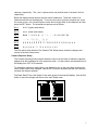
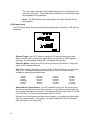
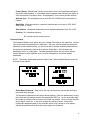
Time Date Setup
The Time Date Setup screen is used to format the multiplexer’s time and date settings and
to setup the daylight savings time option. The NEXT option at the bottom of the screen
leads to the Daylight Savings Time setup screen. The EXIT option saves the settings and
exits the Time & Date Setup screen.
Date Format: There are three date options to choose from where MM = month, DD = day,
and YYYY = year.
USA
MM-DD-YYYY
EURO
DD-MM-YYYY
ASIA
YYYY-MM-DD
Hour Format: The hour format options are: “24 Hour” for military time, or “AM/PM” for clock
time.
5
Date Set: Use the arrow buttons on the front panel to move the cursor position for the year,
month, and date. The SET button decreases the number. The ESC button increases the
number.
Time Set: Use the arrow buttons on the front panel to move the cursor for the hour,
minutes, and seconds. The SET button decreases the number. The ESC button increases
the number.
Daylight Savings: If you are in an area that does not have Daylight Savings Time, set this
option to OFF. When you set this to ON, you must set the start and stop dates and times.
Start: Set the month and day (date) for the beginning of daylight savings time in your area.
Stop: Set the month and day (date) for the ending of daylight savings time in your area.
The BACK option at the bottom of the screen reverts back to the Time & Date Setup screen.
The EXIT option saves the settings and exits the Daylight Saving Setup screen.
Camera Title Setup
The Camera Title Setup screen allows the user to enter a title for each camera. The
maximum length of the title is 24 characters, including spaces.
To set the camera title, select the desired camera so the image appears in the display
window. The < and > buttons to the left and right of the display window are used to move
the cursor position when using the mouse. The SET button on the front of the unit is also
used to move the cursor position.
Underneath the display window the <<, <, >, and >> arrow buttons are used to select the
camera. The << and >> options move to the beginning and end of the list of available
6
cameras, respectively. The < and > options move one position back or forward in the list
respectively.
Below the display window buttons are two rows of characters. There are a total of six
character sets that can be displayed. To move to the next or previous character set, move
the cursor to the < and > button options on the left and right sides of the character set, then
press the SET button. The character set options are as follows:
Set 1:
A to Z (upper case letters)
Set 2:
a to z (lower case letters)
Set 3:
Blank ! “ # $ % & ‘ ( ) * + , - . / 0 1 2 3 4 5 6 7 8 9
Set 4:
: ; , = . ? [ \ ] ^ _ ‘ { | } ~
Set 5:
À Á Â Ä Ç È É Ê Ë Ì Î Ï Ñ Ò Ó Ô Ö Ù Ú Û Ü ß à á â
Set 6:
ä ç è é ê ë ì í î ï ñ ò ó ô ö ù ú û ü
The Exit option at the bottom of the Camera Title Setup screen saves the changes and
returns to the main Setup menu.
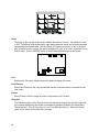
Camera Sequence Setup
The Camera Sequence Setup screen allows the user to set the order in which the cameras
appear when the multiplexer is in the sequence mode. It is also used to set the dwell time of
the display from OFF to 99 seconds.
To change the camera or dwell setting, use the arrow keys on the front panel to move the
cursor to the option to be changed. Use the SET button to decrease and the ESC button to
increase the number selection.
The Stack Dwell Time is the length of time each group of cameras will display. Use the Exit
button to save the settings and return to the main Setup menu.
7
Alarm Setup
When the Alarm Reset Button is set to ON, alarm events can be cleared using the front
panel buttons or the Pop Up menu. When set to OFF, the only way to clear the alarm is to
enter the Setup Menu.
The Alarm Screen Format option sets the display mode that the multiplexer defaults to when
an alarm occurs. The options are: Full, 4x4 Screen, and Unchanged.
The Alarm Dwell Time can be set from 1 to 99 seconds. The screen will automatically
sequence in a multi-alarm condition.
The Alarm setup screen has four sub-menu screens to setup alarm actions. These are
described in the following pages.
Alarm In Setup
The Alarm In setting options are NO (Normally Open), NC (Normally Closed), or OFF. The
Exit option saves the changes and returns to the Alarm Setup menu.
Alarm Action Setup
There are two screens for the Alarm Action Setup as shown below. The Next and Back
buttons toggle between the two screens. The Exit button saves the settings and returns to
the main Alarm Setup menu.
8
Buzzer: When set to ON, the multiplexer’s internal buzzer sounds upon an alarm
condition.
Alarm Screen: When set to ON, the screen display changes to the one defined in the
Alarm Screen Format menu during an alarm condition.
Message Latch: When set to ON, an “A” displays on the screen when an alarm
conditions occurs. It remains on the screen until it is cleared.
Recording: This allows the user to select how video will be recorded during an alarm
condition. INT interleaves images from the camera with an alarm every other field,
thereby providing more images from the camera. When there are multiple alarms, the
cameras with alarms are interleaved. The ONLY option records images from only the
camera with an alarm condition. UNC leaves the recording parameters unchanged.
Spot Monitor : When set to ON, the Spot Monitor display the camera with an alarm
condition. When there are multiple alarms, cameras with alarms display sequentially.
When set to OFF, the Spot Monitor display do not change during an alarm condition.
Hold Time: The Hold Time setting allows the user to set the alarm actions to last from 1
to 99 seconds. Hold Time is applicable only if the alarm action is set to Timed OUT.
Action: The action options are Timed, Latched, and Trans. When Timed is selected,
the alarm “times out” at the designated hold time unless the user clears it earlier. The
Latched setting means the alarm remains active until the operator acknowledges it. The
Trans (transparent) setting means the alarms are not latched and cannot be cleared by
the user.
Motion Action Setup
There are two screens for the Motion Action Setup as shown below. The Next and Back
buttons toggle between the two screens. The Exit button saves the settings and returns to
the main Alarm Setup menu.
9
Buzzer: When set to ON, the multiplexer’s internal buzzer sounds upon a motion alarm
condition.
Alarm Screen: When set to ON, the screen display changes to the one defined in the
Alarm Screen Format menu during a motion alarm condition.
Message Latch: When set to ON, an “M” displays on the screen when a motion alarm
condition occurs. It remains on the screen until it is cleared.
Recording: This allows the user to select how video will be recorded during a motion
alarm condition. INT interleaves images from the camera with an alarm every other field,
thereby providing more images from the camera. When there are multiple alarms, the
cameras with alarms are interleaved. The ONLY option records images from only the
camera with an alarm condition. UNC leaves the recording parameters unchanged.
Spot Monitor : When set to ON, the Spot Monitor display the camera with a motion
alarm condition. When there are multiple alarms, cameras with alarms will display
sequentially. When set to OFF, the Spot Monitor display do not change during a motion
alarm condition.
Video Loss Action Setup
The Video Loss Action Setup screen allows the user to set up the action the multiplexer
takes when there is a video loss condition.
10
Buzzer: When set to ON, the multiplexer’s internal buzzer sounds upon a video loss
condition.
Alarm Screen: When set to ON, the screen display changes to the one defined in the
Alarm Screen Format menu during a video loss condition.
Message Latch: When set to ON, a “V” displays on the screen when a video loss
condition occurs. It remains on the screen until it is cleared.
Spot Monitor : When set to ON, the Spot Monitor display the camera with a video loss
condition. When there are multiple alarms, cameras with alarms will display sequentially.
When set to OFF, the Spot Monitor display do not change during a video loss condition.
Hold Time: The Hold Time setting allows the user to set the alarm actions to last from 1
to 99 seconds.
Alarm History List
The Alarm History List displays historical alarm information for up to 256 events. The arrow
options moves the screen display forward or backwards within the list. The << and >>
options move the screen to the beginning or end of the list, respectively. The < and >
options move the screen backward or forward one page, respectively.
The Clear option erases the information from the list. A confirmation screen appears when
this option is selected, allowing you the option of changing your mind before the information
is deleted.
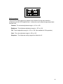
Motion Detection Setup
The Motion Detection Setup menu is used to set the motion detection feature ON or OFF.
Two additional submenu’s provide further setting options scheduling and sensor options.
The All Motion Detection option is a global switch that turns the motion detection function
ON or OFF for all cameras.
11
Motion Detection Schedule Setup
The multiplexer can be set to detect or ignore motion based on a schedule. This feature
allows the motion detection to ignore certain cameras with high activity during normal
business hours yet detect generate an alarm condition when the office is closed and activity
needs to be monitored.
Timer 1 / Timer 2: Each timer can be set to ON or OFF, and Mode 1 or Mode 2. The
Mode settings are described in the Motion Detection Sensor Setup section directly
following this Schedule Setup section.
Start / Stop: The Start and Stop times fore each timer using the 24-hr time format.
Days: The timers can be turned ON or OFF for each day of the week. A check mark
( √ ) activates the day. A circle ( O ) removes the option from the schedule.
Motion Detection Sensor Setup
Each camera can be set to two different modes of motion detection. The parameter sets for
each Mode are shown on the following Motion Detection Sensor Setup screen.
A small window in the upper right portion of the screen displays the camera view. The < and
> options move the camera displayed in the window back or forward by one. The << and >>
options move the camera scene to the first or last in the sequence.
12
On / Off: This turns the motion detection option for the selected mode either ON or
OFF.
Sensitivity: The Sensitivity option determines the luminance change that must occur in
the target area before the multiplexer reads the change as motion. The lowest
sensitivity number is 01. The highest sensitivity number is 16.
Delay Time: The Delay Time is used to make adjustments for scenes that have sudden
changes such as lights and shadows created by headlights or nearby traffic. The delay
can be set from 0 to 5 seconds.
Hold Time: The Hold Time can be set from 1 to 99 seconds.
Grid Setup: The Grid Setup option brings up the Motion Detection Sensor Setup
screen shown below on the left.
•
Set: Highlights the grid area.
•
Dot / Line / All: Determines how many targets will be turned ON or OFF.
DOT = single target, LINE = row of targets, ALL = all of the targets.
•
Reverse: Sets all targets to the reverse side.
•
Test: When selected, it brings up the test screen shown on the previous page
(to the right of the Motion Detection Sensor Setup screen).
13
The Test screen shows when the multiplexer detects motion by drawing a box
around the active area. This provides instant feedback on whether the settings
are acceptable for the application.
Reset: The Reset option returns all settings to the motion detection sensor
setup defaults.
VCR System Setup
The VCR System Setup screen provides optional settings when connecting a VCR with the
multiplexer.
External Trigger: Set to OFF when not using the VCR synchronizing trigger pulse.
When using the VCR’s synchronizing trigger pulse, set to match the VCR’s signal by
selecting + for positive edge sensing and – for negative edge sensing.
Panic Rec Buzzer: When set to ON, a buzzer sounds every 20 seconds. Setting this
option to OFF disables the buzzer.
VCR Type: Selecting this brings up a list of VCRs. Select the VCR you are using from
the list. If it is not listed select the User Define option. The VCR model numbers
available to choose from are listed below.
AVR30
AVR30A
AVR960
AVR960SR
TLS9072
SRT7072
SRT7168
AGRT600A
AGTL500
AG6540
AGRT650
AG6740
RT24A
LTC392461
LTC396361
KV7024A
KV7168A
KV9168A
KV9096A
SVT168E
SVT40E
SVT168
TLC2100
TLC2100HD
Normal Record / Alarm Record: If a VCR is selected from the list, the user must set
the Hour for the Normal and Alarm Record options. If User Define is selected, both the
Hour and the Field options must be set. The setting for the Hour ranges from 001 to 960
(1hr to 960 hrs). For Field, the setting ranges from 001 to 480.
Although you can set Normal and Alarm hours the same, you usually want higher quality
video in an alarm situation. For example, you might set Normal to 24-hour time-lapse
(024) and Alarm to 2-hr mode (002).
14
Camera Picture Adjustment
The Camera Picture Adjustment screen is used to individually adjust the Contrast,
Brightness, Tint, Color, and Sharpness of each of the cameras. It is recommended that no
adjustments be made using this option until the actual cameras and monitors have been
adjusted.
The center window displays the camera view selected for adjustment. To move backward or
forward one camera position, use the < and > options under the center display window. To
move to the beginning or end of the camera list, use the << and >> options.
Contrast: The contrast adjustment range is –100 to +153.
Brightness: The brightness adjustment range is –127 to +126.
Tint: The tint adjustment range is –127 to +126. (Not available for PAL operation.)
Color: The color adjustment range is –103 to +114.
Sharpness: The sharpness setting ranges from Nominal to 5.
Macro Setup
The Macro Setup screen is used to access the recording and scheduling capabilities of the
multiplexer.
Macro Record Setup
The multiplexer can record up to 16 macros on the 16-channel multiplexer. Selecting any of
the Record Start buttons brings up a live screen where actions taken on the front panel
buttons will be recorded as a macro. The password protection operations are excluded from
this feature.
15
Macro Schedule Setup
The Macro Schedule feature allows the user to schedule up to 20 events that use a
recorded macro. Select the Event option (01 through 20) and set the ON/OFF option to ON
to activate it. Select the Macro number (01 through 16) to correspond to the event, then set
the hour, minute, and day(s) of the week the event is to occur. A check mark (√) indicates
the day has been selected (enabled).
Unit Setup
The Unit Setup screen provides options for changing the basic settings on the multiplexer
such as language, key lock, and resetting the unit to the factory default settings.
04/18/2003
Language: The language options for the multiplexer are English, French, Italian,
German and Spanish.
Key Lock: To prevent unauthorized use of the front panel keys, set this option to ON.
When the keys are locked a password is required to access the unit. Pressing any
button or clicking the mouse will bring up the password screen. Enter the Admin User
password to unlock the keys.
16
Factory Reset: Selecting the Factory Reset option returns all user defined settings to
the factory default setting. A confirmation screen appears when selecting this option to
verify the request for a factory reset. See Appendix C for the factory default settings.
Network Type: The multiplexer can be set to RS-232, RS-485 when connected to a
network.
Baud Rate: When connected to a network, the baud rate can be set to 1200, 2400,
4800, 9600, or 19200.
Unit Address: Networked multiplexers can be assigned addresses from 001 to 255.
Protocol : A is multiplexer protocol.
B1 is dome camera control protocol.
Password Setup
The Password Setup screen allows the user to assign PIN codes to the supervisor. Keep a
copy of the supervisor password in a safe place. Once you have changed the supervisor
password from the default setting, you will not be able to access protected areas without it.
An supervisor password is required to access the Setup Menu. After changing the
passwords, keep it in a safe place. The new passwords will be the only way to access
certain features of the multiplexer once you have changed from the factory default
passwords.
NOTE: The factory default passwords are listed in the Technical Specifications section at
the back of this manual.
Setup Menu Password: When set to ON, only the supervisor can access the Setup
menu and make changes.
The supervisor Password screen shown below appears. Enter the password by moving
the cursor over the desired number and pressing the SET key. As you enter each digit,
the circles fill in and the cursor moves to the right one position. Once you have entered
all four digits, select OK. If you have entered an incorrect number, an Incorrect
Password message displays for ten seconds, then the unit returns to a live display.
Repeat the process and re-enter the correct supervisor Password.
17
CHAPTER 3
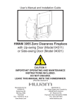
PRODUCT OVERVIEW
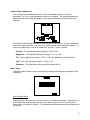
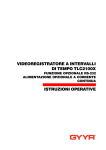
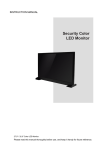
Front Panel Buttons
M ENU
Front View of 16-channel Multiplexer
MENU Press MENU to switch the Setup Menu.
VCR (
) Pressing this button switches the multiplexer into VCR playback mode or VCR
preview mode.
) to switch the multiplexer into VCR playback mode. Press 2nd
OPERATION : Press VCR(
and then VCR (
) to switch the VCR preview mode.
MACRO ( { M }) Plays a Macro.
OPERATON : Press MACRO ( { M }) and then a camera button to play macro 1 to 16.
REC Put a camera in the Panic Record mode.
OPERATION : Press REC and then a camera button to put that camera in the panic record
mode.
FULL (
) Puts the multiplexer in Full-Screen mode or 3+4 display mode.
OPERATION : Press FULL ( ) and the currently selected camera displays full screen. Press
another camera button will display that camera full screen. Press 2nd and then FULL ( ) to
display the 3+4 mode.
PIP (
) PIP (Picture in Picture) inserts a selected camera as a small image in the main image.
OPERATION : Press PIP ( ) and then the camera button of the camera you want displayed in
the insert. Press 2nd and then PIP ( ) to display the PIP4 mode.
18
2x2 (
) Puts the multiplexer in 2x2 display mode or 1+7 display mode.
OPERATION : Press 2x2 ( ) and four cameras display on the screen. Press 2nd and then
2x2 ( ) to display the 1+7 mode.
3x3 (
) Puts the multiplexer in 3x3 display mode or 2+8 display mode.
OPERATION : Press 3x3 (
) and nine cameras display on the screen. Press 2nd and then
) to display the 2+8 mode.
3x3 (
4x4 (
) Puts the multiplexer in 4x4 display mode or 1+12 display mode.
OPERATION : Press 4x4 (
) and sixteen cameras display on the screen. Press 2nd and
) to display the 1+12 mode.
then 4x4 (
SEQUENCE (
) Put the multiplexer in the Sequence mode.
OPERATION : Press Sequence (
) to start or stop all cameras sequencing while in the 2x2,
) while in the Full-Screen mode to start or stop a
3x3 and PIP modes. Press Sequence (
) to Stack Sequence which sequences through
user sequence. Press ESC and Sequence (
multi-format screens.
2nd 2nd button can be used to assign cameras to the Spot monitor.
OPERATION : Press 2nd and then camera button of the camera you want displayed on that
Spot monitor.
FREEZE (
) This button freezes the video.
OPERATION : Press FREEZE ( ) to freeze the video from the currently selected camera.
Press ESC then FREEZE ( ) to freeze the video from all the cameras.
ZOOM (
) This button enters the Zoom mode.
OPERATION : Press ZOOM (
) to enter the ZOOM mode.
SET This button has several functions; it brings up a Popup Menu, sets selections on the OSD
menus and decreases numbers in the number setup function.
OPERATION : Press SET to enter the Popup Menu or to set a selected item from on of the
menus.
19
ESC This button has several functions; it acts as a “Cancel” button, clears Cameo selections
and increases numbers in the number setup function.
OPERATION : Press ESC to cancel entries, clear the Cameo or to decrease the number.
UP, DOWN, LEFT, RIGHT ( ) The Up, Down, Left and Right buttons are used whenever you
need to move the cursor, highlight bar or Cameo window.
OPERATION : Press the arrow corresponding to the direction you want to move.
1 to 16 These buttons are used to make camera selections or enter numbers as needed.
20
CHAPTER 4
MENU SETUP AND OPERATION
POP–Up Menu
Pressing the ACCEPT button on the front of the unit causes the Pop Up menu to appear. The
menu options includes Live Cam Change, VCR Cam Change, Zoom, Full, Panic Record,
Freeze, Sequence, and Utilities.
Live Camera Change
The Live Cam Change option on the Pop Up menu allows the user to assign any camera to
an active cameo. The following screen shows the options for the 16 channel unit.
VCR Camera Change
The VCR Camera Change option on the Pop Up menu is only available when the unit is in
the VCR Playback mode. Like the Live Camera Change, the VCR Camera Change option
allows the user to assign any camera to a cameo view. The following screen shows options
for the 16 channel unit.
21
Zoom
The digits on the top right of the screen indicate the amount of zoom. The maximum zoom
is X32. The picture insert at the bottom right shows the entire scene with a center rectangle
representing the zoomed area. Use the IN and OUT options to zoom in or out of the area.
Use the arrow buttons to move the center rectangle left, right, up or down, to position it in an
area to zoom. Use the FREEZE option to freeze the displayed image on the screen.
Full
Selecting the Full option causes the active camera to display full screen.
Panic Record
When Panic Record is ON, only the selected camera is recorded and it is recorded in realtime mode.
Freeze
When Freeze is ON, the image is frozen on the screen until it is reset.
Sequence
The Sequence option on the Pop Up menu can activate the sequencing for all the cameras
not currently displayed on the screen or a sequencing pattern defined in the Setup Menu.
The options are: Turn All Cam Seq On and Turn User Set Seq On. Select the Cancel
option on the menu to exit without any changes.
22
Utilities
The Utilities option on the Pop Up menu brings up another Pop Up menu with additional
options.
OSD Change
The OSD Setup screen allows the user to select the text that is to appear on the screen and
to select the color. Border Line is the border around the images. “Lv” stands for Live. “Pb”
stands for Playback. The Camera Number, Camera Title, and Time & Date text can be set
to On or Off.
Text can be turned On or Off for Vloss (V), Alarm (A), Motion (M), Freeze (F) and Sequence
(S). The Motion Box text is the box that appears on the screen showing the area where
motion has been detected. The Active Box refers to the window box of the actively selected
camera.
Color options for the text and border are: black, gray, white, red, green, yellow, magenta,
cyan, and blue. To reset the text and board colors to the factory default setting, select the
Default Color option button.
23
Screen Protect
The Screen Protect feature allows the user to protect their setup against unauthorized use.
Alarm Reset
Alarm Reset is used to reset a sounding alarm.
Spot Output
The Spot Output screen allows the user to assign different camera to the spot monitor.
Macro Playback
The Macro Playback option allows the user to select which macro will play.
Alarm List
The Alarm List option brings up the Alarm History List.
Playback Format
The multiplexer can play back tapes that were recorded using multiplexers designed by
different manufacturers. The Playback Format option allows the user to select from the
settings: OWN, Dedicated Micros, Robot (Sensormatic), Pelco, and Kalatel (Impac).
24
PB Picture Adjust
The PB Picture Adjust option only appears on the Utilities Pop Up menu when the
multiplexer is in the VCR Playback mode. It allows the user to adjust images played back
from the VCR.
Contrast: The contrast adjustment range is –101 to +152.
Brightness: The brightness adjustment range is –127 to +126.
Tint: The tint adjustment range is –127 to +126. (Not available for PAL operation.)
Color: The color adjustment range is –95 to +122.
Sharpness: The sharpness setting ranges from Nominal to 5.
25
This page intentionally left blank.
26
APPENDIX A TROUBLESHOOTING
Problem
Check
No Video (black screen)
Check power connections
No Video (one camera)
Check camera power and coaxial cable
No Video (jumbled colors)
Make certain the multiplexer is set correctly for your system
(NTSC or PAL)
Fuzzy Image (one camera)
Check camera focus
Bad video (one camera)
Check the loop through connector. If a cable is attached, make
certain it is connect to another video device on the other end.
Wrong Language
Change the language in the Setup Menu
Buttons do not work
Unlock buttons in Setup Menu
Recorded Video Rolls
Check VCR configuration in Setup Menu. Use the trigger pulse
from the multiplexer for optimum synchronization with a time-lapse
VCR.
Tape Plays Only 4x4
Make certain the video cable to the VCR input is connected to the
VCR OUT of the multiplexer.
Too Many Motion Alarms
Adjust the sensitivity of the motion detection grid. Adjust size of
grid required to activate motion alarm. Make certain only the area
you want to detect motion is activated.
Motion Not Detected
Adjust the sensitivity of the motion detection grid. Adjust size of
grid required to activate motion alarm. Make certain only the area
you want to detect motion is activated.
27
APPENDIX B
REMOTE CONTROL OPERATION
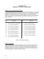
Remote Control for Daisychained Multiplexers
If you are using a computer to control two or more daisy-chained multiplexers, you need to send
a re-address command to select the multiplexer to control. (Up to 16 multiplexers can be daisychained.) Re-address commands are not printable characters; you need an 8-bit binary
address or hex value to select which daisy-chained multiplexer you control. If you lose power to
one or more multiplexers, you will need to use the re-address command again to select the
correct multiplexer.
HEX
RESULTS
HEX
RESULTS
00
NUL (changes active multiplexer)
09
9 (9th connected multiplexer)
01
1 (1st connected multiplexer)
0A
10 (10th connected multiplexer)
02
2 (2nd connected multiplexer)
0B
11 (11th connected multiplexer)
03
3 (3rd connected multiplexer)
0C
12 (12th connected multiplexer)
04
4 (4th connected multiplexer)
0D
13 (13th connected multiplexer)
05
5 (5th connected multiplexer)
0E
14 (14th connected multiplexer)
06
6 (6th connected multiplexer)
0F
15 (15th connected multiplexer)
07
7 (7th connected multiplexer)
10
16 (16th connected multiplexer)
08
8 (8th connected multiplexer)
< Table 1 > Re-Address Commands
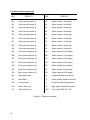
Remote Command Set
Simple three-character ASCII commands represent single or combination front panel button
press on the multiplexer. The effect of a button press or remote command depends on the
multiplexer’s current status. Check the multiplexer’s current status before issuing a remote
command. Because this multiplexer has a different front keys from the old model, some new
commands are added to control the multiplexer correctly.
28
ASCII
MULTIPLEXER KEY
ASCII
MULTIPLEXER KEY
/MU
MENU
/01
Camera 1
/TP
VCR
/02
Camera 2
/MA
MACRO
/03
Camera 3
/SX
RECORD
/04
Camera 4
/FZ
FULL
/05
Camera 5
/PP
PIP
/06
Camera 6
/22
2x2
/07
Camera 7
/33
3x3
/08
Camera 8
/44
4x4
/09
Camera 9
/SQ
SEQUENCE
/10
Camera 10
/2N
2ND
/11
Camera 11
/FR
FREEZE
/12
Camera 12
/ZO
ZOOM
/13
Camera 13
/ST
SET
/14
Camera 14
/ES
ESC
/15
Camera 15
/UP
UP
/16
Camera 16
/DO
DOWN
/LE
LEFT
/RI
RIGHT
< Table 2 > Front key emulation commands
29
Functional remote commands
HEX
RESULTS
HEX
RESULTS
/S1
Panic record (camera 1)
/X1
Select camera 1 for display
/S2
Panic record (camera 2)
/X2
Select camera 2 for display
/S3
Panic record (camera 3)
/X3
Select camera 3 for display
/S4
Panic record (camera 4)
/X4
Select camera 4 for display
/S5
Panic record (camera 5)
/X5
Select camera 5 for display
/S6
Panic record (camera 6)
/X6
Select camera 6 for display
/S7
Panic record (camera 7)
/X7
Select camera 7 for display
/S8
Panic record (camera 8)
/X8
Select camera 8 for display
/S9
Panic record (camera 9)
/X9
Select camera 9 for display
/SA
Panic record (camera 10)
/XA
Select camera 10 for display
/SB
Panic record (camera 11)
/XB
Select camera 11 for display
/SC
Panic record (camera 12)
/XC
Select camera 12 for display
/SD
Panic record (camera 13)
/XD
Select camera 13 for display
/SE
Panic record (camera 14)
/XE
Select camera 14 for display
/SF
Panic record (camera 15)
/XF
Select camera 15 for display
/SG
Panic record (camera 16)
/XG
Select camera 16 for display
/AV
Stop panic record
/_U
Up (press & hold arrow button)
/AF
Setup Menu
/_D
Down (press & hold arrow button)
/AU
Factory Reset
/_L
Left (press & hold arrow button)
/AD
Alarm History List
/_R
Right (press & hold arrow button)
/AL
Alarm History List
/_AR
Time / Date OSD ON / OFF
<Table 3 > Remote commands
30
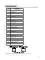
Connector PIN Assignments
The table below provides a reference for the connector PIN assignments of the multiplexer.
PIN
Number
Connector PIN
Assignment
1
Alarm Input 1
2
Alarm Input 2
3
Alarm Input 3
4
Alarm Input 4
5
Alarm Input 5
6
Alarm Input 6
7
Alarm Input 7
8
Alarm Input 8
9
RS-232 RX Input
10
RS-232 TX Input
11
RS-232 RX Output
12
RS-232 TX Output
13
VCR Trigger Input
14
Alarm Input 9
15
Alarm Input 10
16
Alarm Input 11
17
Alarm Input 12
18
Alarm Input 13
19
Alarm Input 14
20
Alarm Input 15
21
Alarm Input 16
22
Alarm Hold Input
23
Alarm Output Common
24
Alarm Output NC
25
Alarm Output NO
NOTE : If termination of RS-485 network is required, short pin 3 and pin 4.
31
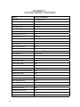
APPENDIX C FACTORY DEFAULT SETTINGS
32
Setting
Default Configuration
Date Format
US (MM/DD/YY)
Time Format
24-hour
Daylight Savings
OFF
Stack Dwell Time
3 seconds
Sequence Dwell Time
3 seconds
Alarm Reset Button
ON
Alarm Screen Format
4x4
Alarm Dwell Time
3 seconds
Alarm Input Polarity
NO (Normally Open)
Alarm Buzzer
ON
Alarm Screen
ON
Alarm Message Latch
ON
Alarm Recording
INT (Interleaving)
Alarm Spot Monitor Output
ON
Alarm Hold Time
20 seconds
Alarm Action
Timed Out
Alarm Relay
ON
Motion Alarm Buzzer
OFF
Motion Alarm Screen
OFF
Motion Alarm Message Latch
ON
Motion Alarm Recording
INT (Interleaving)
Motion Alarm Spot Monitor Output
OFF
Motion Alarm Relay
OFF
Vloss Buzzer
ON
Vloss Screen
OFF
Vloss Message Latch
ON
Vloss Spot Monitor Output
ON
Vloss Hold Time
20 seconds
All Motion Detection
ON
Motion Detection Timer
OFF
Sensitivity
10
Delay Time
0 seconds
Setting
Default Configuration
Motion Hold Time
5 seconds
Target Grids
All Grids ON
External Trigger
OFF
Panic Record Buzzer
ON
VCR Type
Standard VHS
VCR Normal Record Time
2 Hours (NTSC), 3 Hours (PAL)
VCR Alarm Record Time
2 Hours (NTSC), 3 Hours (PAL)
Camera Contrast
000
Camera Brightness
000
Camera Color
000
Camera Tint
000
Camera Sharpness
000
Language
English
Key Lock
OFF
Network Type
RS-232
Baud Rate
1200
Unit Address
001
Protocol
A
Setup Menu Password
OFF
Password Code
5555
VCR Picture Adjustment
000
Border Line
ON (Black)
Live Camera Number
ON (White)
PB Camera Number
ON (Blue)
Live Camera Title
ON (White)
PB Camera Title
ON (Blue)
Live Time, Date
ON (White)
PB Time, Date
ON (Blue)
Vloss Text
ON (White)
Alarm Text
ON (White)
Motion Text
ON (White)
Freeze Text
ON (Red)
Sequence Text
ON (White)
Motion Box
OFF (Blue)
33
APPENDIX D SPECIFICATIONS
Operating Defaults
Display Format
Operation Mode
4x4 multi-screen format
Live
Video Format
NTSC / PAL
Standard
Video Level
Camera Inputs / Outputs
Loop through Output
VCR Input: Composite
Main Output: Composite
Auxiliary Output
1.0V p-p, 75 ohms
1.0V p-p, 75 ohms
1.0V p-p, 75 ohms
1.0V p-p, 75 ohms
1.0V p-p, 75 ohms
Resolution
Sampling
Full (Active)
1/ 4 Size
1/ 9 Size
1/ 16 Size
VCR Out (full)
Spot Out
720 x 480
648 x 448
324 x 224
216 x 149
162 x 112
720 x 480
Analog
Sampling Standard
Y:Cb:Cr
Gray Scale
Color
CCIR 601 (4:2:2)
256 levels
16 million (True Color)
Video Memory
Main Display
VCR Output
64Mb SDRAM
64Mb / 16Mb SDRAM
Refresh Rate (fields / sec)
Full, PIP, Squish, Zoom, Spot Out
Priority mode (major)
(minor)
Spot Out
60
60
30 / number of cameras
60
Power Requiements
12 Vdc, 2.5 Amps
Power Adaptor
100 - 240 Vac Universal Adaptor
Dimensions
Unit size
34
(720 x 576)
(648 x 518) (10 to 9 down-scaling)
(324 x 259)
(216 x 173)
(162 x 129)
(720 x 576)
17”(W) x 1.73”(H) x 12.2”(D)
432(W) x 44(H) x 310(D)mm
Weight
Unit Weight
5.31 Ibs (2.4 Kgs)
Operating Environment
Ambient Temperature
Ambient Humidity
32° to 95° F (0° to 35° C)
10% to 90% non-condensing
35
16-Channel
Color Multiplexer
36
50301683A