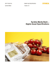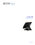
1
EverServ 7000 M7700-XX Users Guide PN770503801 This material has been created in order to accommodate a wide range of restaurant operations and your specific business practices and system configuration may differ slightly from what is represented in this material. While ParTech, Inc. (“PAR”) takes great care to ensure the accuracy of these materials, all material is provided “as is” without warranty of any kind, either express or implied, including, but not limited to, warranties of merchantability or fitness for a particular purpose. PAR does not make any warranties or representations that the materials will meet your requirements or that the operations of the hardware will be uninterrupted or error free. Trademark Notices: The PAR logo, Boundless Hospitality by PAR logo, PAR EverServ™, the PAR EverServ logo and PixelPoint® are all trademarks of PAR Technology Corporation, the parent company of ParTech, Inc. or its affiliates. All other product names used throughout this material are trademarks of the respective companies. No such use of any trademark is intended to convey endorsement or other affiliation with these companies. Reproduction: Copyright © 2010 ParTech, Inc. All rights reserved. This publication, or any part thereof, may not be reproduced or transmitted in any form or by any means, electronic or mechanical, including photocopying, recording, storage in an information retrieval system, or otherwise, without the prior written permission of ParTech, Inc., PAR Technology Park, 8383 Seneca Turnpike, New Hartford, NY 13413‐4991; Phone: (315) 738‐0600. 2 TABLE OF CONTENTS INTRODUCTION 4 GLOSSARY OF TERMS 4 EQUIPMENT DESCRIPTION SPECIFICATIONS MOUNTING 5 7 8 WALL MOUNT BIOS Introduction Starting Setup Using Setup Getting Help BIOS Menu Bar Main Advanced ACPI Configuration S5 RTC Wake Settings CPU Configuration SATA Configuration Intel ® Rapid Start Technology Intel TXT (LT) Configuration PCH‐FW Configuration Intel Anti‐Theft Technology Configuration AMT Configuration Acoustic Management Configuration USB Configuration SMART Settings Super IO Configuration Hardware Health Configuration Intel ® Smart Connect Technology Network Stack Intel RC Drivers Version Detail CPU PPM Configuration Chipset Boot Security Settings Exit Event Log Configuration ROUTINE MAINTENANCE CARE OF EQUIPMENT CLEANING EQUIPMENT 9 13 13 13 13 13 13 14 15 16 17 18 19 19 20 21 22 23 23 24 25 26 27 28 29 30 30 31 32 33 34 35 36 36 36 3 INTRODUCTION The following guide provides information about the EverServ 7000. It is presented in five sections as outlined in the table below. Introduction Register cabling diagram, sample system configurations. Equipment Description Specifications, a detailed description of each system components. Turn On/Off Turning on/off EverServ register. Mounting Attaching EverServ 7000 unit to wall mount. BIOS Provides information on BIOS configurations. GLOSSARY OF TERMS ♦ LCD – Liquid Crystal Display ♦ VGA – Video Graphics Array ♦ EFT – Electronic Funds Transfer ♦ LAN – Local Area Network ♦ DDR – Double Date Rate ♦ POS – Point of Sale ♦ BIOS – Basic Input Output System ♦ PCI – Peripheral Component Interconnect ♦ PnP – Plug and Play ♦ IDE – Integrated/Intelligent Drive Electronics ♦ ACPI – Advanced Configuration and Power Interface 4 EQUIPMENT DESCRIPTION POS REGISTER Item Description 1. Power Indicator Shows that power is present, blinks when unit is in sleep mode. 2. LCD Display A touch screen that shows programming or order information. 3. Magnetic card reader Accepts employee keycards. Provides access to functions. Not present on all registers. 4. Pedestal Cable Access Door Allows access to cables from pedestal of unit. 5. Customer Display Displays to the customer order total, tax total, and any change due. It may also show present advertisement information or messages. 1 2 3 4 5 5 CONNECTOR WELLS Item Description 1. PS2 Port Allows connection of a PC keyboard or mouse. 2. USB 2.0 Ports Connects to coin dispensers, remote customer displays, remote order displays, EFT devices, printers. 3. Network Port Connects to a LAN cable. 4. USB 3.0 Ports Connects to coin dispensers, remote customer displays, remote order displays, EFT devices, printers. 5. COM RJ45 Port Connects to external peripherals. 6. COM RJ45 Port Connects to external peripherals, supplies power +12V or +5V. 7. COM 5 Connects to customer display VFD options 4x20, graphic VFD. 8. Audio Jack Connects audio devices like speakers or headphones. 9. DVI-I Connects to external digital or analog display. 10. 24V Power USB Connects to powered USB devices. 11. 12V Power USB Connects to powered USB devices. 12. Cash Drawer Receptacles Connects to cash drawers. 13. 12V Power Connects to other devices like coin dispensers or printers. 14. 19V Power Input Provides DC power to unit. NOTE: Power must be removed prior to motherboard chassis removal. Trained personnel only. Thumbscrews should be tightened with a tool after both initial installation and subsequent access to the panel. 15. Power Switch Provides power for removable head display. 16. LED Status Lights LED indicators for standby (rd), HDD (green), and PWR (green). NOTE: TOTAL COMBINED OUTPUT OF 24V PWR USB, 2X12V PWR USB, AND 12V ACCESSORY OUTPUT IS 100W MAX. CASH DRAWER OUTPUT: TYP 24V@1AMP 200MS, MAX 24V@1AMP 500MS. CD2 WILL NOT FIRE UNTIL CD1 SHUTS DOWN, AND VICE VERSA. 2 4 1 3 14 11 5 6 7 8 9 10 12 13 16 15 6 SPECIFICATIONS FEATURES Description Part Number TOUCH: Projected CAP Flat Resistive Surface CAP Standard Resistive M7700-00 M7700-10 M7700-20 M7700-30 PROCESSORS: i5-2390T i3-2100T G620T Pentium F7142 F7141 F7140 MEMORY: 4GB DDR3 SDRAM 8GB DDR3 SDRAM 16GB DDR3 SDRAM F7240 F7241 F7242 DISPLAYS: 4x20 VFD on Pedestal POP (Paper Insert) Dbl Byte VFD None 12” 1024x768 Graphics LCD F7621 F7643 F7624 F7620 M7555-01 MAGNETIC STRIP READERS: Blank Cover Plate 3 Track USB Swipe Reader 3 Track PS/2 Reader 2 Track F7340 F7342 F7343 F7341 PROGRAM/DATA STORAGE: 320 GB 2.5” SATA HDD 320 GB 2.5” w/RAID 32 GB SSD 2.5” SATA HDD 8 GB SD F7440 F7442 F7445 F7417B Mounting K7022 KITS: MISCELLANEOUS OPTIONS: SD Flash Disk: 2GB 4GB 8GB 266004402 266004403 266004404 7 MOUNTING If you are converting your counter POS to a wall mounted unit you must first detach base as shown below, otherwise continue to wall mounting instructions on page 8. DETACH BASE (If converting from counter unit to wall mounted unit): Detach EverServ 7000 Panel POS head from base of unit by: Laying unit on face, connector well facing you Removing two screws where head of unit attaches to base as shown below 8 WALL MOUNT To mount EverServ 7000 Panel POS unit to the wall, connect assembly hinge to bracket wall mount using 8-32 screws. Mount bracket wall mount assembly to wall in 4 locations using hardware provided by installer. Hardware will be determined by installer depending on mounting surface. Place power supply into area shown and dress cables. Item Description 1. Wall Bracket Mounting Holes Holes used for mounting bracket to wall using hardware provided by installer. 2. Bracket Wall Mount Bracket that connects to the wall. 3. Power Supply Storage Area Holds power supply brick into place. 4. Assembly POS7 Hinge Attaches to EverServ 7000 unit. 5. Screw PHP w/Cap 8-32x3/8 Screws to attach bracket wall mount to assembly hinge. 2 1 3 5 4 9 Attaching Mounting Brackets on EverServ 7000 Panel POS Lay EverServ 7000 panel POS on its face with bottom facing you Place black mounting plate PN001985401 on back of EverServ 7000 panel POS lining up screw holes as shown below Place silver mounting plate PN001900501 on top of black mounting plate, lining up screw holes as shown below 10 Place silver mounting plate PN001900601 on top of silver mounting plate PN001900501, lining up screw holes as shown below Insert 4 screws into screw holes to secure three mounting plates to back of EverServ 7000 panel POS 11 Attaching EverServ 7000 Panel POS to Wall Mount Attach EverServ 7000 panel POS to wall mount by sliding panel POS into wall mount bracket as shown below Secure EverServ 7000 panel POS to wall mount using (2) screws PN 848004206 12 BIOS Introduction This user manual describes the AMI BIOS setup program and configuration options of the EverServ motherboard. The BIOS setup program allows users to modify the basic system configuration of the EverServ motherboard. Starting Setup The AMI BIOS is activated when the computer is turned on. The setup program can be activated in one of two ways. 1. Press the DELETE key as soon as the system is turned on or 2. Press the DELETE key when the “Press Del to enter SETUP” message appears on the screen. 0. If the message disappears before the DELETE key is pressed, restart the computer and try again. Using Setup Use the arrow keys to highlight items, press ENTER to select, use the PageUp and PageDown keys to change entries, press F1 for help and press ESC to quit. Navigation keys are shown in. Key Function Up arrow Down arrow Left arrow Right arrow Esc key Page Up key Page Dn key F1 key F10 key Move to previous item Move to next item Move to the item on the left hand side Move to the item on the right hand side Main Menu – Quit and not save changes Status Page Setup Menu and Option Page Setup Menu -- Exit current page and return to Main Menu Increase the numeric value or make changes Decrease the numeric value or make changes General help, only for Status Page Setup Menu and Option Page Setup Menu Save all changes, only for Main Menu Getting Help When F1 is pressed a small help window describing the appropriate keys to use and the possible selections for the highlighted item appears. To exit the Help Window press ESC or the F1 key again. BIOS Menu Bar The menu bar on top of the BIOS screen has the following main items: Main Changes the basic system configuration. Advanced Changes the advanced system settings. Chipset Changes the chipset settings. Boot Changes the system boot configuration. Security Changes the security settings. Save & Exit Selects exit options and loads default settings. Event Logs Changes the event log settings. The following sections completely describe the configuration options found in the menu items at the top of the BIOS screen and listed above. 13 Main The Main BIOS menu appears when the BIOS Setup program is entered. The Main menu gives an overview of the basic system information. BIOS Menu 1: Main Î System Information The System Information lists a brief summary of different system components. The fields in System Information cannot be changed. The items shown in the system overview include: AMI BIOS: Displays auto-detected BIOS information o Version: Current BIOS version o Build Date: Date the current BIOS version was made Processor: Displays auto-detected CPU specifications o Speed: Lists the processor speed System Memory: Displays the auto-detected system memory. o Size: Lists memory size The System Overview field also has two user configurable fields: Î System Time [xx:xx:xx] Î Use the System Time option to set the system time. Manually enter the hours, minutes and seconds. System Date [xx/xx/xx] Use the System Date option to set the system date. Manually enter the day, month and year. 14 Advanced Use the Advanced menu to configure the CPU and peripheral devices through the following sub-menus: WARNING: Setting the wrong values in the sections below may cause the system to malfunction. Make sure that the settings made are compatible with the hardware. ACPI Settings S5 RTC Wake Settings CPU Configuration SATA Configuration Thermal Configuration Intel ® Rapid Start Technology Intel TXT (LT) Configuration PCH-FW Configuration Intel Anti-Theft Technology Configuration AMT Configuration Acoustic Management Configuration USB Configuration SMART Settings Super IO Configuration H/W Monitor Intel ® Smart Connect Technology Network Stack Intel RC Drivers Version Detail CPU PPM Configuration Switchable Graphics BIOS Menu 2: Advanced 15 ACPI Configuration The ACPI Configuration menu configures the Advanced Configuration and Power Interface (ACPI) and Power Management (APM) options. BIOS Menu 3: ACPI Configuration Î Enable ACPI Auto Configuration Î Enable Hibernation Î ACPI Sleep State Î S3 Video Repost Î Wake on PS/2 Keyboard Î Wake on PS/2 Mouse Î USB Wakeup Î Touch Screen Wakeup 16 S5 RTC Wake Settings Use the S5 RTC Wake Settings menu to enable or disable System wake on alarm event. Î Wake System with Fixed Time [Disabled] Î Î Use the Wake System with Fixed Time to enable or disable System wake on alarm event. Disabled Default Disables System wake on alarm event. Wake System with Dynamic Time [Disabled] Î Use the Wake System with Dynamic Time to enable or disable wake on current time and increase minutes. Disabled Default Disables System 17 CPU Configuration Use the CPU Configuration menu to view detailed CPU specifications and configure the CPU. BIOS Menu 4: CPU Configuration The CPU Configuration menu (BIOS Menu 4) lists the following CPU details: Manufacturer: Lists the name of the CPU manufacturer Brand String: Lists the brand name of the CPU being used Frequency: Lists the CPU processing speed FSB Speed: Lists the FSB speed Cache L1: Lists the CPU L1 cache size Cache L2: Lists the CPU L2 cache size The following CPU Configuration menu item can be configured. Hyper-threading Active Processor Cores Limit CPUID Maximum Execute Disable Bit Intel Virtualization Technology Hardware Prefetcher Adjacent Cache Line Prefetch TCC Activation Offset Primary Plane Current Value Secondary Plane Current Value 18 SATA Configuration Use the SATA Configuration menu to view detailed SATA specifications. Intel ® Rapid Start Technology Use the Intel ® Rapid Start Technology menu to enable or disable Intel ® Rapid Start Technology. 19 Î Intel (R) Rapid Start Technology [Disabled] Use the Intel (R) Rapid Start Technology to enable or disable Intel ® Rapid Start Technology. Î Disabled Default Rapid Start Technology is set to disabled. Intel TXT (LT) Configuration Î Secure Mode Extensions (SMX) Use the Secure Mode Extensions (SMX) to enable or disable secure mode extensions. Î Enabled Default SMX is enabled. 20 PCH-FW Configuration Use the PCH-FW Configuration menu to enable or disable MDES BIOS Status Code. Î MDES BIOS Status Code [Disabled] Î Î Use the MDES BIOS Status Code to enable or disable MDES BIOS Status Code. Disabled Default MDES BIOS Status Code is disabled Enabled MDES BIOS Status Code enabled 21 Intel Anti-Theft Technology Configuration Use the Intel Anti-Theft Technology Configuration menu to enable or disable anti theft in BIOS. Î Intel Anti-Theft Technology Use the Intel Anti-Theft Technology to enable or disable anti-theft. Î Disabled Default Anti-Theft is disabled. 22 AMT Configuration Use the AMT Configuration menu to enable or disable Active Management Technology BIOS Extension. Acoustic Management Configuration Use the Acoustic Management Configuration menu to enable or disable Automatic Acoustic Management. 23 Î Automatic Acoustic Management Î Use the Automatic Acoustic Management to enable or disable Automatic Acoustic Management. Disabled Default Automatic Acoustic Management is disabled. USB Configuration Use the USB Configuration menu to read USB configuration information and configure the USB settings. BIOS Menu 5: USB Configuration Î USB Configuration Î USB Devices Enabled The USB Devices Enabled field lists the USB devices that are enabled on the system. Î USB Function [4 USB Ports] Use the USB Function BIOS option to enable or disable a specified number of USB ports. If only two USB ports are being used, disabling the remaining six USB frees up system resources that can be redirected elsewhere. Î Legacy USB Support [Enabled] The Legacy USB Support BIOS option refers to USB mouse and USB keyboard support. Normally if this option is not enabled, any attached USB mouse or USB keyboard does not become available until a USB compatible operating system is fully booted with all USB drivers loaded. When this option is enabled, any attached USB mouse or USB keyboard can control the system even when there is no USB driver loaded on the system. Î Disabled Legacy USB support disabled Î Enabled Default Legacy USB support enabled 24 Î USB 3.0 Support [Enabled] Î Î Use the USB 3.0 Controller BIOS option to enable or disable the USB 3.0 controller Disabled USB 3.0 controller disabled Enabled Default USB 3.0 controller enabled SMART Settings Use the SMART Settings menu to enable or disable SMART Self Test. Î SMART Self Test [Enabled] Î Î Use the SMART Self Test option to enable or disable SMART Self Test. Disabled Self Test disabled Enabled Default Self Test enabled 25 Super IO Configuration Use the Super IO Configuration menu to set or change the configurations for the FDD controllers, parallel ports and serial ports. BIOS Menu 6: Super IO Configuration 26 Hardware Health Configuration The Hardware Health Configuration menu shows the operating temperature, fan speeds and system voltages. BIOS Menu 7: Hardware Health Configuration The following system parameters and values are shown. The system parameters that are monitored are: System Temperatures: The following system temperatures are monitored o System Temperature o CPU Temperature o PCH Temperature Fan Speeds: The CPU cooling fan speed is monitored. o System Fan 1 Speed o System Fan 2 Speed Voltages: The following system voltages are monitored o CPU Core o +3.30V o PCH IO o Sys. Memory o VSB5V o VCC3V o VSB3V o VBAT 27 Intel ® Smart Connect Technology Use the Intel ® Smart Connect Technology menu to enable or disable ISCT Configuration. Î ISCT Configuration [Disabled] Î Î Use the ISCT Configuration to enable or disable ISCT Configuration. Disabled Default ISCT Configuration disabled Enabled ISCT Configuration enabled 28 Network Stack Use the Network Stack menu to enable or disable UEFI network stack. Î Network Stack [Disable Link] Use the Network Stack to enable or disable UEFI network stack. Î Disable Link Default Disables UEFI network stack. 29 Intel RC Drivers Version Detail Use the Intel RC Drivers Version Detail menu to see version details. CPU PPM Configuration Use the CPU PPM Configuration menu to enable or disable Intel SpeedStep. 30 Chipset Use the Chipset menu to access the PCH-IO configuration and System Agent (SA) configuration menus. WARNING! Setting the wrong values for the Chipset BIOS selections in the Chipset BIOS menu may cause the system to malfunction. 31 Boot Use the Boot menu to configure system boot priority options. BIOS Menu 8: Boot Î Boot NumLock State Î Î Use the Boot NumLock State to allow Number lock setting to be modified during boot up. On Default Allows Num Lock on keyboard on boot up. Quiet Boot Î Use the Quiet Boot to allow the boot up screen options to be modified between POST messages or OEM Logo. Enabled Default Enables Quiet Boot. Boot Option Priorities: Set to determine sequence in which computer checks which device to boot from. 32 Security Settings Use the Security Settings menu to set passwords for administrator/user. Î Administrator Password Use Administrator Password to set Administrator Password. Î User Password Use User Password to set User Password. 33 Exit Use the Exit menu to load default BIOS values, optimal failsafe values and to save configuration changes. BIOS Menu 9:Exit Î Save Changes and Exit Use the Save Changes and Exit option to save the changes made to the BIOS options and to exit the BIOS configuration setup program. Î Discard Changes and Exit Use the Discard Changes and Exit option to never save the changes made to the BIOS options and to exit the BIOS configuration setup program. Î Save Changes and Reset Use the Save Changes and Reset option to reset system saving current changes. Î Discard Changes and Reset Use the Discard Changes and Reset option to reset system discarding current changes. Î Save Changes Use the Save Changes option to save the changes made to the BIOS options and to not exit the BIOS configuration setup program. Î Discard Changes Use the Discard Changes option to load the original value of this boot time. Î Restore Defaults Use the Restore Defaults option to reset all standard default values. 34 Event Log Configuration Use the Event Log Configuration menu to view or delete the system event log storing POSt and run-time errors and events. BIOS Menu 10: Event Log Configuration Î Change Smbios Event Log Settings Enable the Change Smbios Event Log Settings option to change the Smbios Event Log configuration. Î View Smbios Event Log Enable the View Smbios option to view Smbios event logs. 35 ROUTINE MAINTENANCE CARE OF EQUIPMENT Prevent costly damage to your POS equipment: ♦ Never allow a unit to drop. ♦ Never allow napkins, boxes, or other objects to block air vents on the printers, videos, PCs, or registers. These units have to "breathe" to operate efficiently. ♦ Make sure nylon or rubber grommet (washer) protects each hole punched through the counter top and other metal surfaces. Metal edges may cut through cables. ♦ Never break open a roll of coins by striking it against the cash drawer. ♦ Never switch a cash drawer with any other housing (case). The cash drawer and its housing are a matched set. ♦ Never drag a printer. Dragging weakens the cable. Lift a printer to move it. ♦ Always turn off or unplug units during power failures. ♦ Never unplug a unit when the power switch is on. CLEANING EQUIPMENT Clean the surfaces of all POS units often: 1. Turn off the unit. 2. Dampen a clean towel with carbonated water or Windex. Make sure the towel is damp, not saturated. 3. Wipe off the unit with the damp towel. Never pour carbonated water directly on a unit. WARNING: Never use abrasive materials to clean the touch screen on a register. A scratch on the surface could disable the register, and result in costly repairs. 4. When done, turn the unit back on. 36 SAFETY ♦ Before connecting cables or devices to connector wells, please turn off the power first thus preventing potential ESD damage. ♦ The service related to human safety is not allowed because this device may have the possibility of the radio interference. ♦ As this equipment has undergone EMC registration for business purpose (“A” class), the seller and/or the buyer is asked to beware of this point and designed to be used in the area, except for home use. ♦ Risk of explosion if battery is replaced by an incorrect type. Dispose of used batteries according to the instructions. 37 PAR PHONE NUMBERS Service USA: 800.382.6200 Canada: 800.387.4963 Parts USA: 800.PAR.PART Canada: 800.387.4963 Sales Continental USA except New York: 800.448.6505 New York State Only: 800.533.6311 Outside Continental USA: 315-738-0600 Driver Support http://www.partech.com/restaurant/services/contact-support/ 38