1
iDigi Platform for Embedded Linux
User Manual
90002000_B
2012 Digi International Inc.
All Rights Reserved.
Digi, Digi International, the Digi logo, the Digi website, Digi ESP, iDigi, the iDigi logo, the iDigi
website, iDigi Device Cloud, iDigi Developer Cloud, iDigi Manager Pro, iDigi Web Services API,
ConnectCore 9C, ConnectCore Wi-9C, ConnectCore 9P, ConnectCore Wi-9M 2443, ConnectCore
Wi-MX51, ConnectCore Wi-MX53, ConnectCard for i.MX28, and Digi Connect ME are trademarks
or registered trademarks of Digi International, Inc.
All other trademarks mentioned in this document are the property of their respective owners.
Information in this document is subject to change without notice and does not represent a
commitment on the part of Digi International.
Digi provides this document “as is,” without warranty of any kind, either expressed or implied,
including, but not limited to, the implied warranties of fitness or merchantability for a particular
purpose. Digi may make improvements and/or changes in this manual or in the product(s) and/or
the program(s) described in this manual at any time.
This product could include technical inaccuracies or typographical errors. Changes are periodically
made to the information herein; these changes may be incorporated in new editions of the
publication.
Digi International Inc.
11001 Bren Road East
Minnetonka, MN 55343 (USA)
+1 877 912-3444 or +1 952 912-3444
http://www.digiembedded.com
2
Contents
Contents .............................................................................................. 3
1. Introduction .................................................................................... 5
1.1. What is the iDigi Device Cloud? ............................................................................................... 5
1.2. What are the applications of the iDigi platform? ...................................................................... 5
1.3. iDigi concepts ........................................................................................................................... 5
1.3.1.
1.3.2.
1.3.3.
1.3.4.
1.3.5.
1.4.
1.5.
1.6.
1.7.
Cloud computing ............................................................................................................................... 5
Protocols ........................................................................................................................................... 6
Applications ...................................................................................................................................... 6
iDigi Web Services API ..................................................................................................................... 6
iDigi Manager Pro ............................................................................................................................. 6
Conventions ............................................................................................................................. 7
Abbreviations............................................................................................................................ 8
Supported Platforms ................................................................................................................ 8
Requirements ........................................................................................................................... 8
2. First steps in iDigi .......................................................................... 9
2.1. Creating a new iDigi account ................................................................................................... 9
2.2. Adding iDigi to your platform .................................................................................................... 9
2.2.1.
2.2.2.
2.2.3.
2.2.4.
Adding the device sample applications ............................................................................................. 9
Including wireless tools ................................................................................................................... 10
Build the project .............................................................................................................................. 11
Configuration file ............................................................................................................................. 11
2.3. Start the embedded device .................................................................................................... 11
2.3.1.
2.3.2.
Configuring the network interface ................................................................................................... 11
ADDP daemon ................................................................................................................................ 12
2.4. Register your device to your iDigi account ............................................................................. 13
2.4.1.
2.4.2.
2.4.3.
Manual registration ......................................................................................................................... 14
Device ID ........................................................................................................................................ 15
Check that your device is registered ............................................................................................... 15
2.5. Registration of a Vendor ID .................................................................................................... 15
2.5.1.
2.5.2.
2.5.3.
2.5.4.
2.5.5.
Device type ..................................................................................................................................... 16
Firmware version ............................................................................................................................ 16
Cached data in iDigi ........................................................................................................................ 16
Register a new Vendor ID ............................................................................................................... 17
Instructing devices to supply the Vendor ID .................................................................................... 17
3. iDigi applications ......................................................................... 18
3.1. Methods of communication .................................................................................................... 18
3.1.1.
3.1.2.
Remote Control ............................................................................................................................... 18
Data storage ................................................................................................................................... 18
3.2. Sample applications ............................................................................................................... 18
4. Remote control examples ........................................................... 19
4.1. Device application (idigimanager) .......................................................................................... 19
4.1.1.
4.1.2.
4.1.3.
4.1.4.
4.1.5.
Device properties ............................................................................................................................ 20
File system management ................................................................................................................ 21
Firmware update ............................................................................................................................. 21
Securing the connection ................................................................................................................. 24
Validation of server SSL certificate ................................................................................................. 25
4.2. Device application (idigibuttonled) ......................................................................................... 26
4.2.1.
Testing the buttons and LEDs thread.............................................................................................. 27
4.3. Client application (iDigiLedDemo.jar) ..................................................................................... 27
5. Data storage example .................................................................. 30
5.1. Device application (idigistorage) ............................................................................................ 30
5.1.1.
Retrieving data from iDigi ................................................................................................................ 31
3
5.2. Client application (iDigiTankDemo.jar) ................................................................................... 32
6. Application development ........................................................... 35
6.1. iDigi API functions .................................................................................................................. 35
6.1.1.
Functions for remote control ...........................................................................................................35
6.2. The idigibuttonled sample application in detail....................................................................... 36
6.2.1.
6.2.2.
6.2.3.
6.2.4.
6.2.5.
6.2.6.
Source tree .....................................................................................................................................36
RCI requests and replies .................................................................................................................37
Defining custom commands ............................................................................................................38
Implementing the custom commands callbacks ..............................................................................38
Custom commands descriptors and registration .............................................................................41
Rest of code ....................................................................................................................................42
6.3. The client application iDigiLedDemo ...................................................................................... 43
6.4. The idigistorage sample application in detail ......................................................................... 44
6.5. The client application iDigiTankDemo .................................................................................... 44
7. Configuration file ........................................................................ 45
7.1. Section DEVICE_CONFIG_GROUP ...................................................................................... 45
7.2. Rest of sections ...................................................................................................................... 45
8. Known issues and limitations .................................................... 46
8.1. Network connection and interfaces ........................................................................................ 46
8.1.1.
8.1.2.
Gateway IP .....................................................................................................................................46
DNS addresses ...............................................................................................................................46
8.2. Buttons and LEDs on hardware platforms ............................................................................. 46
8.2.1.
8.2.2.
8.2.3.
Digi Connect ME 9210 ....................................................................................................................46
ConnectCore Wi-9M 2443...............................................................................................................46
ConnectCard for i.MX28..................................................................................................................46
8.3. Limitations on file uploads/download ..................................................................................... 47
9. Reference documentation .......................................................... 48
4
1. Introduction
1.1. What is the iDigi Device Cloud?
®
The iDigi Device Cloud™ is a platform that allows for application-to-device data interaction
(messaging), application and device data storage, and remote management of devices. Devices
®
are associated with iDigi through the Internet or other wide area network connections, which allow
for communication between the device, the iDigi server, and customer applications. An important
part of this communication is the transfer of data from a device to iDigi. Users can write applications
that run on devices which pass data (messages) as well as send data to a temporary data cache
on the iDigi platform, to be available for retrieval by iDigi Web Services clients.
The iDigi platform solves some difficult problems for deployment of devices with a communications
interface, and allows the application developer to concentrate on their field of interest without
having to worry about network management, data storage and remote firmware updates.
All of this is available if there is an available connection to the Internet, at least part of the time but
preferably with permanent access. It works behind firewalls, or with direct Internet connections.
1.2. What are the applications of the iDigi platform?
There are many real world applications where iDigi can be very beneficial. One such application is
in energy management, where power utilities can provide remote access and management to
appliances in homes or businesses that put a heavy load on the energy grid. Other applications are
fleet management, where a fleet of vehicles can be monitored from a remote location or building
automation, where lighting can be controlled to save energy. Also, the monitoring and data
collection of a sensor network can be made easier with iDigi. In addition to handling data from your
devices, iDigi supports device management such as upgrading firmware and making configuration
changes.
1.3. iDigi concepts
1.3.1. Cloud computing
Cloud computing is Internet-based computing, whereby shared resources, software, and
information are provided to computers and other devices on demand, similar to the electricity grid.
5
The cloud is a metaphor for the Internet in cloud computing, based on how it is depicted in
computer network diagrams and as an abstraction for the complex infrastructure it conceals.
You can consider iDigi as a platform that lives in this cloud and allows your computers and
embedded devices to communicate with each other even when they are at different locations.
1.3.2. Protocols
iDigi works in combination with different communication protocols:
-
ADDP: (Advanced Device Discovery Protocol) is a Digi proprietary network protocol that allows
for discovery of devices connected to an Ethernet LAN. The protocol also allows basic network
configuration of the device.
-
EDP: (Easy Device Protocol) is a Digi proprietary network protocol for communicating with
iDigi.
-
RCI: (Remote Command Interface) is a high level communication protocol written in XML. This
XML protocol is the one used for communications in the cloud between user-end applications,
iDigi to remotely command and communicate with the embedded device, and with the iDigi
server or with any client application that resides on the cloud.
1.3.3. Applications
When working on the cloud there are two distinct types of applications:
-
Device applications: applications running on the embedded device, that send data to and
receive data from iDigi.
-
Client applications: applications that may run on any PC, or other device in the cloud, and use
iDigi Web Services to communicate with the device application running on the embedded
device.
1.3.4. iDigi Web Services API
The iDigi Web Services API™ is a set of protocols and standards for data interchange between
applications. Different applications written in different programming languages and running in
different hardware architectures can use web services to interchange data over networks, such as
the Internet.
1.3.5. iDigi Manager Pro
The iDigi Manager Pro™ service is a Digi web portal where users can register their devices for
remote management and firmware updates.
6
1.4. Conventions
This document uses these conventions, frames, and symbols to display information:
Convention
Use
Style
New terms and variables in commands, code, and other input.
Style
In examples, to show the contents of files, the output from commands.
In text, the C code.
Variables to be replaced with actual values are shown in italics.
For menu items, dialogs, tabs, buttons, and other controls.
Style
In examples, to show the text that should be entered literally.
$
A prompt that indicates the action is performed in the host computer.
#
A prompt that indicates the action is performed in the embedded device.
Menu name > option
A menu followed by one or more options; for example, File > New.
This manual also uses these frames and symbols:
A warning that helps to solve or to avoid common mistakes or
problems.
A hint that contains useful information about a topic.
$
$
A host computer session.
Bold text indicates what must be input.
# A embedded device session.
# Bold text indicates what must be input.
An excerpt of a file
Bold text indicates what must be input.
7
1.5. Abbreviations
ADDP
Advanced Device Discovery Protocol
EDP
Easy Device Protocol
GPIO
General Purpose Input Output
HAL
Hardware Abstraction Layer
HTTP
Hypertext Transport Protocol
LAN
Local Area Network
LED
Light-Emitting Diode
MAC
Media Access Control
OEM
Original Equipment Manufacturer
RCI
Remote Command Interface
SCI
Server Command Interface
SSL
Secure Sockets Layer
UI
User Interface
XML
eXtensible Mark-up Language
1.6. Supported Platforms
iDigi for Digi Embedded Linux is currently supported on the following platforms:
ConnectCore™ 9P 9360
ConnectCore™ 9C/Wi-9C
ConnectCore™ 9P/Wi-9P 9215
Digi Connect ME 9210
ConnectCore™ 9M/Wi-9M 2443
ConnectCore™ Wi-i.MX51
ConnectCore™ Wi-i.MX53
ConnectCard™ for i.MX28
®
Depending on which platform is being used, the information displayed in
dialogs and output messages may vary from that shown in this manual.
1.7. Requirements
• A Linux distribution with Digi Embedded Linux version 5.2 or later is required.
• To run iDigi Manager Pro one of the following web browsers is required: Firefox 3+, Safari 4+,
Chrome 3+ or Internet Explorer 7+. It is required that the web browser has the latest JAVA
virtual machine and JAVA is enabled. To check that you have the latest version of JAVA
enabled please visit: http://www.java.com/en/download/help/testvm.xml
• JAVA Runtime Environment is also needed for running sample client applications.
If you do not have JAVA installed, install it with the following command (on a Kubuntu distribution):
# sudo apt-get install sun-java6-jre sun-java6-plugin sun-java6-fonts
8
2. First steps in iDigi
This section helps you get familiar with the iDigi Device Cloud platform, and guides you through the
process of creating your iDigi account as well as discovering and registering embedded devices to
your iDigi account.
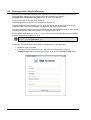
2.1. Creating a new iDigi account
To create a new iDigi account:
1.
Navigate to http://developer.idigi.com in a web browser.
2.
Click on “Are you a new user?” and fill in the form to create a new iDigi account.
2.2. Adding iDigi to your platform
Support for iDigi is included in Digi Embedded Linux distribution, it also includes:
-
Sample Applications that run on the embedded device side.
-
Libraries to support iDigi.
-
Client Sample Applications that run on a host PC and communicate with the
application running on the device.
-
Documentation (this manual).
-
Header files for iDigi application development.
-
Configuration file for iDigi applications.
-
Source code for the device sample applications and for the client sample applications.
The following instructions assume you have created a Digi Embedded Linux project with support for
applications and root file system. If you have not done so, please refer to Digi ESP™ for Embedded
Linux documentation (accessible via an icon in your desktop after installing Digi Embedded Linux)
for instructions.
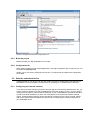
2.2.1. Adding the device sample applications
Open the configuration tool on your project (by pressing the Configure Project button in Digi ESP
or running make xconfig if using the command line) and in the Applications section select the
following elements:
-
ADDP daemon
-
iDigi buttons & LEDs example
-
iDigi manager
-
iDigi storage example
9
The necessary iDigi libraries will be automatically added to your root file system.
The iDigi Buttons and LEDs application makes use of the two user buttons and
user LEDs on the development board. For the application to work it is necessary
that their associated GPIOs are not being used by any other driver or
application.
If using platform ccw9m2443js, the wireless interface uses LED1 of the
development board for showing the wireless status. You must disable this
feature in the kernel configuration under Device Drivers > Network device
support > Wireless LAN > Digi Piper Wifi support > Enable GPIO for Wifi status
LED.
If you are using the ConnectCard for i.MX28 platform, AUART1 and AUART2
conflict with the user buttons and LEDs. Please refer to your OS documentation
to disable them to be able to run the user and button led demo. Please refer to
the Hardware Reference manual of the platform for specific instructions about
needed configuration jumpers.
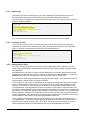
2.2.2. Including wireless tools
If you own a wireless capable platform, you must add the following wireless applications to your
root file system since iDigi makes use of them when configuring the wireless adapters.
Go to Rootfs Configuration > Pre-built applications and enable:
-
Wireless-tools package
-
WPA supplicant package
10
Save the changes and exit the configuration tool.
2.2.3. Build the project
Build and install your Digi Embedded Linux project.
2.2.4. Configuration file
When adding support for iDigi sample applications, the iDigi configuration file is copied to your root
file system at /etc/idigi.conf.
Initially, you do not need to modify this file. Section 7 Configuration file explains the configuration
file in detail.
2.3. Start the embedded device
Update the flash of your device with the new system and start it. Please refer to the Digi ESP for
Embedded Linux documentation for instructions on updating your embedded device firmware.
2.3.1. Configuring the network interface
To be able to remotely manage your device through iDigi and use the iDigi Web Services API, you
need to configure the device so that it establishes a connection to iDigi. For this, you may need to
configure the IP address, subnet mask and gateway of your embedded device’s network interface,
as well as the DNS addresses, so that it can route packets to the Internet and resolve Internet
names. All these network settings can be permanently configured in the U-Boot console. Please
refer to the U-Boot Reference Manual for instructions on configuring the network parameters of
your embedded device.
11
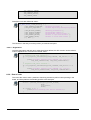
To see if your device has access to the Internet, you can perform a ping to the Digi website:
# ping www.digi.com
PING www.digi.com (172.16.1.69):
64 bytes from 172.16.1.69: seq=0
64 bytes from 172.16.1.69: seq=1
64 bytes from 172.16.1.69: seq=2
64 bytes from 172.16.1.69: seq=3
56 data
ttl=250
ttl=250
ttl=250
ttl=250
bytes
time=339.719
time=349.424
time=363.303
time=343.482
ms
ms
ms
ms
Note, the first time this is done it may take some seconds for the embedded device to resolve the
name before the ping packets can be transmitted.
If you cannot ping an Internet address, check that you have a default route in your system:
# route
Kernel IP routing table
Destination Gateway
10.101.0.0
*
default
mygateway
Genmask
255.255.0.0
0.0.0.0
Flags Metric Ref
U
0
0
UG
0
0
Use Iface
0
eth0
0
eth0
and that your system has registered your DNS addresses set in U-Boot:
# cat /etc/resolv.conf
# Automatically generated
nameserver 2.2.2.2
nameserver 8.8.8.8
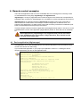
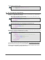
2.3.2. ADDP daemon
The ADDP daemon (addpd) will launch automatically at start, allowing the device to be discovered
by iDigi. You can see it start in the boot messages:
...
Starting addpd: OK
...
You can also check that the addpd daemon is running with:
# ps | grep addpd
254 root
708 S
275 root
1120 S
/usr/sbin/addpd
grep addp
If the daemon is not running, you can launch it manually with:
# /etc/init.d/S81addpd.sh start
Starting addp daemon: OK
ADDP daemon listens to multicast Digi device discovery packets on your LAN.
12
2.4. Register your device to your iDigi account
To manage your device remotely via iDigi, you must first register it within your iDigi account.
iDigi Manager Pro uses JAVA language. It is important that your PC has the
latest version of JAVA runtime environment installed and that the Internet
browser has JAVA enabled. Refer to section 1.7.Requirements for more
information
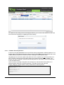
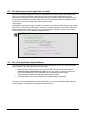
To register your device:
1.
Navigate to http://developer.idigi.com in a web browser.
2.
Login with the username and password you created in section 2.1 Creating a new iDigi
account.
3.
Open the Devices page by selecting the Devices menu within the iDigi Manager Pro tab.
Initially, your account will not have any registered devices.
13
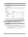
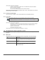
4.
To add a device, click the Add Devices button ( ) within the Devices page’s toolbar. The
Add Devices applet will be displayed.
5.
Click the Discover button to display all the Digi devices discovered in your LAN through
the ADDP protocol.
6.
Locate your Linux Embedded Device by its Hardware Name and MAC or IP address.
Select your device from the list and click OK to add the device to your account. If the
checkbox on top is enabled, the device will be configured to connect to that iDigi server
and the device will reboot.
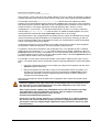
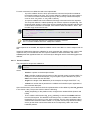
2.4.1. Manual registration
If your device does not appear in the list, you can add it manually if you know the MAC address of
the primary wired Ethernet interface:
1.
2.
Click the Add Manually >> button within the Add Devices applet.
Select the MAC Address option from the drop-down box, then type in the MAC address
of your device’s primary wired network interface.
14
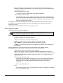
3.
4.
Click Add to add it to the list.
You will be redirected to the previous Add Devices applet page. Your device will now
appear in the list. Select your device entry from the list and click OK.
2.4.2. Device ID
The Device ID is a 16 octet number that uniquely identifies a device within iDigi. For embedded
devices, the Device ID is built using the MAC address of the primary wired Ethernet interface of the
device (typically 'eth0'). In the example above, for a MAC: 01:02:03:04:05:06, the Device ID is
00000000-00000000-010203FF-FF040506 (for clarity, initial zeros on the left part will be hidden).
2.4.3. Check that your device is registered
If your device was successfully registered, it should now appear in your Devices list. Initially it will
appear as Disconnected.
2.5. Registration of a Vendor ID
A Vendor ID is a unique identifier assigned by Digi to an OEM. To understand the need to request
a Vendor ID, the concepts of Device Type and Firmware Version must be introduced and some
background about how iDigi stores information must be given.
15
2.5.1. Device type
The Device type (shown as deviceType) is a string representing a particular kind of device.
Devices with the same deviceType should share a reasonably similar set of features.
This string can be supplied in the configuration file /etc/idigi.conf in your device's rootfs, in section
DEVICE_CONFIG_GROUP:
[DEVICE_CONFIG_GROUP
vendorId=
firmwareVersion=1.0.0.0
deviceType=My Device Type I
companyName=Digi International Inc.
deviceModel=
certificateStore=
]
If no value is given to deviceType the hardware platform name will be used by default.
2.5.2. Firmware version
The Firmware Version (shown as firmwareVersion) is a 32 bit value given as four decimals
separated by periods, which represents the version of the firmware running in your embedded
device. The value must be defined by the user in the configuration file:
[DEVICE_CONFIG_GROUP
vendorId=
firmwareVersion=1.0.0.0
deviceType=
companyName=Digi International Inc.
deviceModel=
certificateStore=
]
2.5.3. Cached data in iDigi
For certain devices, connection to the Internet may be intermittent and/or expensive. For this
reason, data and descriptors (meta-data) are cached on iDigi instead of being constantly polled
and refreshed.
Data presented to you about your device in iDigi Manager Pro is normally data that was cached
sometime in the past and may not be the most up to date real data. iDigi Manager Pro contains a
Refresh button which can be pressed in order to force the query of current data.
A combination of device type and firmware version is used as a key to cache information such as
RCI descriptors, default values, and other information.
Currently, there is no process for acquiring a device type beyond simply choosing one and hoping
that it is available and does not collide. If a collision does occur, there is the possibility of odd
behavior. For instance, if someone connects a device to the iDigi platform with the device type
“VendingMachine” iDigi will attempt to acquire information from this device. This information can
be used for multiple purposes such as generating the management UI for the device or determining
if the device can support file uploads. This information is expensive to acquire, so it is cached in the
platform making it available for any other device that connects using the device type and firmware
version. Additionally, some devices may not support being queried for this information directly, so it
can be loaded into the platform out of band and available for later use.
There is nothing stopping someone else from choosing a device that also has the device type
“VendingMachine”. This device may be significantly different, but the platform will still think it can
apply its cached data to the device type. As a result, the device will have a broken UI, as it will
show management options and other features that may not be applicable to the device.
16
Vendor ID registration is a process that allows third parties to create their own device types without
having to worry about the type already existing, or someone coming in later and overwriting the
cached data for their type.
2.5.4. Register a new Vendor ID
Registering a Vendor ID (shown as vendorId) is optional. If you do not register a Vendor ID, a
common Vendor ID will be assigned allowing you to work normally. The only risk of not registering
a Vendor ID is that another iDigi user chooses the same device type and firmware version as your
device and the collision explained above could occur.
To avoid this from happening, request a new Vendor ID as explained:
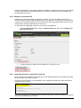
1.
2.
Select the My Account menu within the Administration tab, then click the Register for
new vendor id button:
A unique Vendor ID number will be assigned to your iDigi account.
2.5.5. Instructing devices to supply the Vendor ID
Once a Vendor ID is assigned to your iDigi account, all registered devices must supply the Vendor
ID number when they connect to iDigi.
This can be done by filling the vendorId field in the configuration file with the Vendor ID that was
assigned to your account.
[DEVICE_CONFIG_GROUP
vendorId=0x12345678
firmwareVersion=1.0.0.0
deviceType=
companyName=Digi International Inc.
deviceModel=
certificateStore=
]
If you do not supply one, the default Vendor ID will be used, but you will not be able to manage the
descriptors (meta-data) of your device.
17
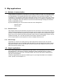
3. iDigi applications
3.1. Methods of communication
iDigi's Data Service facilitates the sending of commands and data requests from client applications
to remote devices. Devices can also push data up to iDigi in the form of XML files that are saved in
the iDigi database. The uploaded files are kept in collections, which are similar to folders. The
organization of the collections reflects the hierarchical nature of a user's groups within iDigi. Clients
can access the data within these collections and then work with it; for example, by displaying it in a
graph on a webpage. Files and collections can also be accessed through the iDigi User Portal as
well as via iDigi Web Services.
By their methodology two communication methods can be distinguished:
-
Remote control
-
Data storage
3.1.1. Remote Control
iDigi supports web services that allows requests to be sent to devices. This can be done using the
Server Command Interface (SCI). Among other things, an SCI request can be used to wrap an RCI
(Remote Command Interface) request. RCI provides a way for users to send a request to a single
device. RCI can be used to get and set information about a device’s settings/state, reboot a device,
update its firmware, etc. It can also be used to send custom requests to a device.
An SCI request allows an RCI request to be sent to multiple devices at once.
3.1.2. Data storage
Applications on a device can easily send any data to iDigi with a simple function call, and the
device and iDigi take care of the details. With this feature, a user can decide which data to send to
iDigi and how often to send it. The data that is sent by the device will usually be in the form of an
XML file that will be stored in iDigi.
3.2. Sample applications
Some sample applications are distributed with iDigi support, each representing one of the methods
described above. In the following chapters, applications will be presented and ran in order to
demonstrate how they work. Then, in another chapter, the source code used to understand the
iDigi API will be explained.
The device applications are stored in subfolder apps/ on your Digi Embedded Linux installation
folder, typically /usr/local/DigiEL-X.Y.
18
4. Remote control examples
There are two applications that run on the embedded device for showing how to remotely control
an embedded device using iDigi: idigimanager and idigibuttonled.
idigimanager is a very tiny application that controls the agent on the device that is responsible for
establishing the connection to iDigi Manager Pro, and allows for remote management of the device.
idigibuttonled is an application based in idigimanager that adds custom user commands, to
demonstrate how to add custom functionality for remote management via Web Services. The
purpose of this application is to allow remote control and monitoring of the device’s hardware (user
LEDs on the development board) through the Internet.
This last example combines the device application itself (idigibuttonled) written in C that runs on the
embedded device, and a client application (iDigiLedDemo) written in JAVA that runs on a desktop
PC.
Both applications (idigimanager and idigibuttonled) launch the client
that establishes the connection to iDigi; therefore, they should not be
running at the same time.
4.1. Device application (idigimanager)
This application runs on the embedded device and calls the iDigi start function that allows remote
control of the device from within iDigi.
If you included this application in your project (as explained in section 2.2.1 Adding the device
sample applications) you can run the application with:
# idigimanager
Application: iDigi Manager
Network support in firmware:
Ethernet
Device ID: 00000000-00000000-0004F3FF-FF690045
Vendor ID: 0xFE080003
Device Type: ConnectCore 9P 9360 on a JumpStart board
Acquired Ethernet MAC address=00:04:f3:69:00:45
IP information:
IP address=10.101.1.143
Netmask=255.255.255.0
Gateway=10.101.1.1
Primary DNS=10.49.2.2
Secondary DNS=10.10.8.62
Initiating client-initiated connection
Finding Service, URL=en://developer.idigi.com
Trying to connect via TCP...
Version OK
Verifying ID
ID Verify Passed
Connected Using TCP to en://developer.idigi.com
19
The application should now be able to connect to iDigi. Click the Refresh button within the Device
page’s toolbar to ensure that your device was successfully connected. Once refreshed, your
device’s status should appear as Connected.
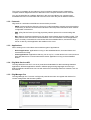
4.1.1. Device properties
You are now able to double-click the device and explore the device’s properties and settings.
Once the Properties Page is opened for a device, various options can be displayed and configured.
The example below shows the Ethernet Interface settings for a device. The System Information
section displays items including System Uptime, Firmware Version, Used Memory, and CPU
Utilization.
Some of the settings are read only, while others can be modified.
20
Be careful when modifying network settings, as a bad configuration might
prevent your embedded device from connecting to the Internet, thus losing the
connection to iDigi.
4.1.2. File system management
The File Management section allows a user to browse through the embedded device’s file system.
This tool also allows some manipulation of the file system such as uploading, downloading, and
deleting files.
Files are transferred via HTTP with base64 encoding which adds an
overhead of around a 33% in the size being transferred.
Transfer of big files is subject to the available free RAM memory in the
embedded system.
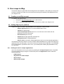
4.1.3. Firmware update
iDigi allows a user to remotely update the firmware of their embedded device (to do so you must be
logged in to iDigi). To remotely update a device’s embedded firmware:
1.
Open the Devices page by selecting the Devices menu within the iDigi Manager Pro tab.
2.
From the devices list, select the device or devices (more than one can be updated at the
same time) that you want to update.
3.
Click the Firmware button within the toolbar, then select Update Firmware....
21
An update firmware dialog will then be displayed allowing you to select a firmware file on your host
PC to be sent to the device for updating the Flash memory.
4.1.3.1. Firmware files and partitions
A device running Digi Embedded Linux has its Flash memory segmented in different partitions. The
partition table can be defined using the U-Boot monitor and the flpart command. Please refer to the
U-Boot Reference Manual for instructions about modifying the Flash partition table.
iDigi Manager Pro's firmware update utility allows the user to update only one Flash partition at a
time. The user, however, does not need to select which partition he/she wants to update. The
partition that will be updated is selected automatically based on the filename of the file being sent
to the embedded device.
There is a table in the iDigi configuration file /etc/idigi.conf that links each Flash partition to a
filename pattern defined by a regular expression. This table can be found within the
FLASH_UPDATE_GROUP section, and by default has the following entries:
[FLASH_UPDATE_GROUP
U-Boot=u-boot.*\.bin
NVRAM=nvram-.*
Splash=splash\.bmp
Kernel=uImage-.*
RootFS=rootfs-.*
UserFS=
]
22
Each entry is formed by a pair:
partition_name=filename_pattern
where partition_name is the name of the Flash partition as given in U-Boot, and filename_pattern is
a regular expression that a filename must match in order to be used to update the referred partition.
For example, the first entry U-Boot=u-boot.*\.bin tells the device to update the U-Boot
partition if the received filename begins with the string u-boot, then it has zero or more characters,
and finishes with the extension .bin (note the dot is escaped with the backslash to have it taken as
a literal character). This regular expression will accept filenames like u-boot.bin, u-bootcc9p9360js.bin, u-boot123.bin... but will reject filenames like uboot.bin, u-boot.img, U-Boot.bin.
The third entry Splash=splash\.bmp tells the device to update the Splash partition only if the
received filename matches the string splash.bmp exactly and no other strings.
The default values in the configuration file are already set up to match the standard binary image
names produced by the Digi Embedded Linux development environment. Normally you will not
want to change the table in the configuration file unless you have decided to modify the standard
names of the images produced by Digi EL.
If a filename matches two or more patterns in the table, the file will be written to the first partition
whose pattern matches the filename. The rest of partitions will be ignored.
If a partition's name does not appear in the configuration file, or if it appears but has no defined
pattern (as it occurs with entry UserFS=) the device will accept, by default, a filename in the form
partitionX where X is the index of the partition in the U-Boot partition table (starting at index 0). So,
if a UserFS partition has an index of 6 in the U-Boot partition table, a file named partition6 (without
extension) will be written to the UserFS partition.
For example, if a user goes to U-Boot and creates a new partition called myTest, which is given
index 7, two things can be done to update this partition using iDigi Manager Pro's firmware update
tool:
•
Leave the configuration file as it is and create your images for this partition with the name
partition7 (without extension).
•
Edit the configuration file and add an entry for the new partition with a new pattern. For
example myTest=mytest\.img which would only accept filename mytest.img (note the
idigimanager application must be stopped and launched again in order to accept any
changes in the configuration file).
Users are encouraged to extend the table in the configuration file to match their specific Flash
partition table.
Firmware updates may take some time as the image files are transferred over
the Internet to your embedded device. The time depends on the size of the
file, and the speed of the connection.
After each partition update, the embedded device will disconnect from iDigi.
The application will automatically reconnect after a number of seconds
defined in the configuration file under the key
clientConnectionReconnectTimeout.
Since the root file system partition is a critical partition, if it is being updated
the device will reboot when the update process is complete (after reboot you
will need to start the idigimanager application again because it does not start
automatically).
23
4.1.4. Securing the connection
Security within iDigi is provided via SSL. By default, connections are not secured. To activate SSL,
open the Devices page by selecting the Devices menu within the iDigi Manager Pro tab. From
the devices list select the device that you want to update, then double-click on the device to open
its Properties page.
From the menu displayed, click on Configuration and then select the iDigi Device Manager
Network option from the list. If you have more than one network interface you must select the one
that is used for connecting the device to the Internet.
If the device’s Connection method setting is set to TCP, change it to SSL then click the Save button
to save your changes. The new connection method will not be applied until the device is
disconnected and reconnected again.
To disconnect the device from iDigi, return to the Devices page and select your device from the list.
within the toolbar and select Disconnect….
Then, click on the Administration button
24
The application will automatically reconnect again after a number of seconds defined in the
configuration file under the key clientConnectionReconnectTimeout. The reconnect timeout value
can be changed (or even disabled) within iDigi under the iDigi Device Manager Connection section.
Verify that the new connection is encrypted via SSL by looking at the messages printed on the
console:
...
Trying to connect via TCP...
Wrapping the connection through SSL
Connected with EDH-RSA-DES-CBC3-SHA encryption
Version OK
...
4.1.5. Validation of server SSL certificate
By default, validation of SSL certificates sent by the iDigi server are disabled. To enable validation
of SSL certificates, open the Devices page by selecting the Devices menu within the iDigi
Manager Pro tab. From the devices list select the device that you want to update, then double-click
on the device to open its Properties page. From the menu displayed, click on Configuration >
iDigi Device Manager Network, then select iDigi Device Manager Network 1. You can turn
required validation ON and OFF by selecting the radio buttons within the Require validation of
server SSL cert option.
This action will tell the embedded device to reject the connection if the certificate sent by the server
could not be authenticated.
Authentication of the server certificate happens in two ways:
-
If the certificate sent by the server is a self-signed certificate, the embedded device
must have the same certificate (PEM format) in the trusted certificates store within the
root file system.
-
If the certificate sent by the server is a CA signed certificate, the embedded device
must have the CA's root certificate (PEM format) in the trusted certificates store within
the root file system.
25
In order to use peer validation you will need to obtain the self-signed or root
CA certificate for the iDigi server you are connecting to.
If peer validation is enabled without the correct CA certificate loaded, the
device will not be able to connect to iDigi.
4.1.5.1. Instructions for configuring Linux for peer certificate validation
1. Download the iDigi Device Cloud CA certificate
Navigate to (http://developer.idigi.com) and login to your account. From the Help &
Downloads menu (in the upper-right corner of the page’s banner) select the Downloads
option. The iDigi Help & Downloads resources page will be displayed. Within the General
Downloads section of the page, locate the iDigi Device Cloud CA Certificate link and
download it. Extract it to your development computer at the place where the rest of your
certificates are stored (for example at /etc/ssl/certs/).
2. Create a symbolic link to the certificate with the name of the certificate's hash
Use the openssl application to obtain the certificate’s hash:
# cd /etc/ssl/certs
# openssl x509 -hash -noout -in idigi-ca-cert-public.crt
789761b3
Then create the symbolic link with the hash:
# ln -s idigi-ca-cert-public.crt 789761b3
3. Set the path to the certificate in the configuration file (/etc/idigi.conf)
Edit the iDigi configuration file on your device rootfs (/etc/idigi.conf) and add set the field
certificateStore to the path where the CA certificate is:
[DEVICE_CONFIG_GROUP
vendorId=
firmwareVersion=1.0.0.0
deviceType=
companyName=Digi International Inc.
deviceModel=
certificateStore=/etc/ssl/certs/
]
Given that targets sometimes haven’t configured the system time (because the
RTC is disabled or not powered) a common problem when activating SSL
certificate validation, is the connection denial due to causes like “Certificate is
not yet valid” or “Certificate expired”.
Please check that the system time and date are properly setup in your target to
avoid these connection problems.
4.2. Device application (idigibuttonled)
This application is based on idigimanager application. It runs on the embedded device and does
the following:
-
Registers custom user command functions that will be called when certain custom RCI
requests arrive at to the embedded device (for controlling the LEDs).
26
-
Launches a thread that polls the pressing of user buttons and toggles the associated
user LEDs. When a user presses BUTTON1, the associated LED1 will toggle its
status. When a user presses BUTTON2, the associated LED2 will toggle its status.
-
Calls the iDigi start function that allows remote control of the device within iDigi.
If using platform cme9210js, BUTTON1 is associated with LED2 and BUTTON2
is associated with LED3. Refer to section 8.2 LEDs on hardware platform.
As explained in section 2.2.1 Adding the device sample applications, no other
interface or application should be using the user GPIOs or LEDs for the
example to work properly.
If you included this application in your project as explained in section 2.2.1 Adding the device
sample applications you can run the application with:
# idigibuttonled
Application: iDigi LEDs & Buttons demo
Network support in firmware:
Ethernet
Device ID: 00000000-00000000-0004F3FF-FF690045
Vendor ID: 0xFE080003
Device Type: ConnectCore 9P 9360 on a JumpStart board
Acquired Ethernet MAC address=00:04:f3:69:00:45
IP information:
IP address=10.101.1.143
Netmask=255.255.255.0
Gateway=10.101.1.1
Primary DNS=10.49.2.2
Secondary DNS=10.10.8.62
Initiating client-initiated connection
Finding Service, URL=en://developer.idigi.com
Trying to connect via TCP...
Version OK
Verifying ID
ID Verify Passed
Connected Using TCP to en://developer.idigi.com
The device will connect to the iDigi server specified in the /etc/idigi.conf configuration file (by default
http://developer.idigi.com).
4.2.1. Testing the buttons and LEDs thread
As introduced previously, the sample application also launches a thread which toggles the user
LEDs upon button presses.
Press the user buttons on the development board and check that their associated LEDs toggle on
each button press.
4.3. Client application (iDigiLedDemo.jar)
The Client application iDigiLedDemo.jar is a JAVA executable that can be found in the DigiEL
installation folder under /usr/local/DigiEL-X.Y/idigi/client_apps/iDigiLedDemo/bin. To execute it in a
Linux PC, Java Runtime Environment must be installed and you must have access to the Internet.
To run it:
$ cd /usr/local/DigiEL-X.Y/idigi/client_apps/iDigiLedDemo/bin/
$ java -jar iDigiLedDemo.jar
27
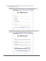
A dialog box will appear. Follow these steps to configure and run the application:
1. Double-click the executable.
2. In the iDigi Account window enter your iDigi username and password, and use
developer.idigi.com for the iDigi Server name. Then click the Connect to iDigi button.
3. The application will connect to your iDigi account and the Device ID combo box will be filled
in with all the devices registered in your iDigi account. Select your Device ID from the
combo box and click Start the application with the selected device.
28
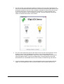
4. The main window of the application displays the status of the two LEDs (representing the
LEDs on the development board) and the two user buttons (representing the buttons on the
development board). A text box is also available to establish the refresh time (the number
of seconds after which a request will be sent to the device, to check the status of the
LEDs). This refresh time can be modified by the user. The time remaining until the next
refresh is showed at the bottom of the window.
5. The JAVA client application performs the same functions as the device application that is
already running on the embedded device. When a user clicks on BUTTON1, the
associated LED1 will toggle its status. When a user clicks on BUTTON2, the associated
LED2 will toggle its status. This has immediate effect on the development board and
demonstrates how a embedded device can be remotely controlled through the Internet.
6. If a user physically presses a button on the development board, the associated LED will
toggle. The JAVA application will not update its status until the refresh period is over.
29
5. Data storage example
The purpose of this example is to allow the device to upload data to the iDigi data storage service
(Data Services). This communication method is typical of devices that do not need to be remotely
controlled, but instead, need to report or log some form of data, to be retrieved asynchronously.
This example is formed using a device application (idigistorage) written in C that runs on the
embedded device plus a JAVA application (iDigiTankDemo) that grabs the data from iDigi and
represents it graphically.
5.1. Device application (idigistorage)
This application simulates an embedded device, controlling different sensors and actuators on a
tank which is filled with a certain liquid:
-
Temperature sensor
-
Level sensor
-
5 valves that control the input/output of liquid
The embedded device should periodically report the measurements of the sensors and the status
of the valves, to keep track of the tank status. Since the application is just an example that runs on
the development board, instead of having sensors and actuators random values will be generated
and they will be limited to a certain range.
The device will periodically push data (including the date and time of the measurements) as an
XML file. The method of formatting data being pushed to iDigi is up to the user. For this example
the following format for the tank data has been designed:
<tank>
<date>2010/03/21</date>
<time>21:55:38</time>
<level>68%</level>
<temperature scale="Celsius">17</temperature>
<valve id="0">closed</valve>
<valve id="1">open</valve>
<valve id="2">open</valve>
<valve id="3">closed</valve>
<valve id="4">open</valve>
</tank>
The file will be saved into the iDigi data storage service (Data Services) to the path /<deviceid>/examples/tank.xml. Again, the path can be anything the user wants (the root folder is always
the Device ID and is added automatically).
Every X seconds the application will generate new data and will send the new file to the same path
(thus overwriting the old file). The period can be set by the user through the command line (with a
minimum of 5 seconds). Default period is 10 seconds.
If you included this application in your project as explained in section 2.2.1 Adding the device
sample applications, you can run the application with:
# idigistorage -t 10
Application: iDigi Storage demo (tank simulation)
File transferred OK
Sleeping for 10 seconds
where -t sets the number of seconds to wait before sending updated data.
30
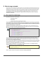
5.1.1. Retrieving data from iDigi
The data file pushed by the embedded device to iDigi can be manually retrieved from the Data
Services page. To open this page, select the Data Services menu within the iDigi Manager Pro
tab.
Double-click on the folder that matches your Device ID, and then on the subfolder titled examples.
The top bar shows the complete file path within iDigi Storage service.
Finally, double-click the tank.xml file to access its contents.
31
5.2. Client application (iDigiTankDemo.jar)
Data files can be retrieved using a PC client application by means of Web Services. All that the
client application needs to do is to send an HTTP GET request to the address
developer.idigi.com/ws/data/<file_path> and it will receive the XML file.
In the example above, the <file_path> would be:
00000000-00000000-00004F3FF-FF123456/examples/tank.xml
The client application iDigiTankDemo.jar is a JAVA executable that can be found in the Digi EL
installation folder under /usr/local/DigiEL-X.Y/idigi/client_apps/iDigiTankDemo/bin.
This client application receives the tank.xml file via Web Services as explained above, then parses
and interprets the data within and represent it in a graphic with the tank.
To execute this application in a Linux PC, you must have the Java Runtime Environment installed
and have access to the Internet. To run it:
$ cd /usr/local/DigiEL-X.Y/idigi/client_apps/iDigiTankDemo/bin/
$ java -jar iDigiTankDemo.jar
A dialog box will appear. Follow these steps to configure and run the application:
1. Double-click the executable.
2. In the iDigi Account window enter your iDigi username and password, and use
developer.idigi.com for the iDigi Server name. Then click the Connect to iDigi button.
32
3. The application will connect to your iDigi account and the Device ID combo box will be filled
with all the devices registered in your iDigi account. Select your Device ID from the combo
box and click Start the application with the selected device.
4. The main window of the application shows the status of a tank, representing the data
reported by the idigistorage application. This data is the tank status (temperature and
level), the status of the five valves, and the date and time when the data was last reported.
A text box is also available to establish the refresh time (the number of seconds after which
a request will be sent to the iDigi server to read the file stored). This refresh time can be
modified by the user. The time remaining to the next refresh is showed at the bottom of the
window.
33
5. The JAVA client application reads the file from within iDigi data storage, and displays the
data in a graphic interface. This application demonstrates how a device can be remotely
monitored using the Internet.
34
6. Application development
The following chapter discusses sample device applications and the iDigi API functions used for
communication between the client application and iDigi.
6.1. iDigi API functions
To use iDigi functionality you must know the following functions:
-
Functions for Remote Control
o idigi_start()
o idigi_register_usercmd()
o idigi_query_attribute()
-
Functions for data storage
o idigi_putfile()
6.1.1. Functions for remote control
6.1.1.1. idigi_start
This function establishes the connection to iDigi Manager Pro in an endless loop.
int idigi_start(void)
It takes no parameters and only returns upon a critical error. This function opens the connection to
iDigi and waits for something to do.
6.1.1.2. idigi_register_usercmd
This function allows the user to register custom callback functions (hooks) that will be called
whenever the embedded device receives a certain RCI request via Web Services.
int idigi_register_usercmd (const rci_desc_cmd_t *descriptor,
rci_desc_error_t *error_descriptor_list)
The function requires two parameters:
-
A descriptor, which is a struct that defines the command name, description, the
process callback, the response callback, and the context.
-
An array of error codes and their description text.
The function returns 0 if the registration was successful or -1 on error.
6.1.1.3. idigi_query_attribute
This function is usually called from within the custom callback functions and allows the user to
retrieve the value of attributes from the XML string received in the RCI request.
char * idigi_query_attribute(void *descriptor_handle, char *name)
35
The function requires two parameters:
-
A pointer to the descriptor handle, which is accessible from within the callback
functions previously registered.
-
The name of the attribute whose value we want to retrieve.
The function returns the string with the attribute’s value, or NULL if the attribute was not found in
the XML string of the RCI request.
6.1.1.4. Functions for data storage
Only one function is needed in order to upload XML files into the iDigi Data Services.
6.1.1.5. idigi_putfile
This function uploads a data buffer to the specified path within the Device ID’s folder.
int idigi_putfile(char *filename, void *file_data, size_t length)
The function requires three parameters:
-
The filename, including any internal path and where to store the data (for example:
“examples/tank.xml”. If the path does not exist it will be created as you go.
-
A pointer to the data buffer.
-
The length of the buffer (in bytes).
The function returns 0 if the upload was successful or -1 on error.
6.2. The idigibuttonled sample application in detail
See section 4.2.Device application (idigibuttonled) for more information on the idigibuttonled
application.
6.2.1. Source tree
The following table shows the different files that form the application, and their functionality:
File
Description
buttonled.c
Contains the callback functions that process and respond to a
custom RCI request that arrives to the embedded device via Web
Services.
platform.c
Contains functions to guess the hardware platform and operate the
LEDs
main.c
Contains the descriptors for the custom commands and the calls to
the API functions that register the callback functions and establish
the connection to iDigi.
36
6.2.2. RCI requests and replies
As introduced in section 1.3.2.Protocols, the Remote Command Interface (RCI) is the high level
communication protocol that the embedded device will use to communicate with iDigi. RCI is just
plain text in XML format.
An RCI request specifies the XML element “rci_request” optionally with a version number.
<rci_request version="1.1">
</rci_request>
An RCI reply specifies the XML element “rci_reply” in a similar way.
<rci_reply version="1.1">
</rci_reply>
6.2.2.1. Commands
The command section describes the action requested (or action performed in replies).
Supported commands are:
Command
Request description
Reply description
query_setting
Request for device settings. May
contain setting group elements to
subset query (only setting group
subset supported. Subsetting
below this level not supported).
Returns requested config settings.
Requests specifying no settings
groups (eg. <query_setting/>) return
all settings.
set_setting
Set settings specified in setting
element. Settings data required.
Empty setting groups in reply indicate
success.
query_state
Request current device state such
as statistics and status. Subelement may be supplied to subset
results.
Returns requested state. Requests
specifying no groups
(eg.<query_state/> return all state.
set_factory_default
Sets device settings to factory
defaults. Same semantics as
set_setting.
Same semantics as set_setting.
reboot
Reboots the device immediately
Empty reboot node indicates success
(the reply is actually sent before the
reboot is performed).
do_command
If the ‘target’ attribute is
‘file_system’ it allows to run file
system related operations.
If the ‘target’ attribute is
‘user_defined’ it allows any custom
callback function to execute.
For file system related operation, it
returns the result of the operation.
For user defined commands, the
reply is defined by the user in a
response callback function.
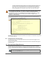
iDigi uses these commands to communicate with the embedded device and represent its
information on the web. For example, when you click on System Information > Device statistics
and press the Refresh button, the following RCI request is sent by iDigi to your device:
<rci_request version="1.1">
<query_state>
<device_stats/>
</query_state>
</rci_request>
37
And the device answers, for example, with:
<rci_request version="1.1">
<query_state>
<cpu>17</cpu>
<uptime>27754.09</uptime>
<totalmem>126764</totalmem>
<freemem>119380</freemem>
</query_state>
</rci_request>
The syntax for each command element and response is predefined and it is not the purpose of this
document to explain all the commands in detail.
The power of RCI resides in the do_command command, which allows you to create your own
custom commands, assign them custom callback functions to process them, and build response
messages.
<rci_request version="1.1">
<do_command target="user_defined">
<my_command my_attribute="my_value"/>
</do_command>
</rci_request>
6.2.3. Defining custom commands
A client application, for example, should be able to:
-
Operate the embedded device's LEDs
-
Show the status of the embedded device's LEDs (which may change if operated
manually on the development board)
In other words, the goal is to be able to set an LED (write) and get back its status (read).
In order to define a custom command for these two operations a user must know how to write a
LED, know the LED they want to operate, and know whether they want to turn the LED ON or OFF.
As an example, the following syntax can be used:
<led_write number="1" control="on"/>
where:
-
led_write is the command
-
number is an attribute that indicates the LED to be operated
-
control is the action to do on the LED
To read an LED, a user only needs to know the LED they want to read.
As an example, the following syntax can be used:
<led_read number="1"/>
A complete RCI request to turn both LEDs on would then look like this:
<rci_request version="1.1">
<do_command target="user_defined">
<led_write number="1" control="on"/>
<led_write number="2" control="on"/>
</do_command>
</rci_request>
6.2.4. Implementing the custom commands callbacks
Now that the syntax that will be used for your custom commands has been defined, callback
functions can be implemented to process commands and respond to them. In the previously
mentioned sample application, the callbacks are implemented in buttonled.c.
38
For each command, two callbacks need to be implemented:
-
A process callback function which processes the command and performs whatever
functionality needs to be done. The process callback is called once for each instance
of a custom command received through RCI (in the previously mentioned example,
once for each <led_write> or <led_read> instance).
-
A response callback which will create the RCI reply to be sent back to the requestor.
The response callback is called repeatedly until it sets a response complete flag. The
response buffer written by this function will be inserted between the start and end tags
of the custom command. For example, if this function writes "MY REPLY TEXT", the
final RCI reply would look like this:
<rci_reply version="1.1">
<do_command target="user_defined">
<led_write number="1" control="on">MY REPLY TEXT</led_write>
</do_command>
</rci_reply>
Process and response callbacks are explained in detail in sections
6.2.4.1.Process callback and 6.2.4.2.Response callback.
If the response is not needed, the response callback can be set to NULL or have it respond with no
text.
Instead of implementing these two callbacks for each command (led_write/led_read), a user could
implement one process callback and one response callback for both commands, and use the
context parameter (explained later on in this manual) to distinguish which command triggered the
callback.
6.2.4.1. Process callback
The prototype for the process callback is:
int process(void *handle, char *data, unsigned length, unsigned long
context)
where:
-
handle is a pointer to the descriptor handle.
-
data is a buffer containing the text portion of the received custom command XML. For
example, if the received command is <mycmd myattr="myval">MYTEXT</mycmd>,
data would contain the text: MYTEXT.
-
length is the length of the data buffer (in the example, the length of MYTEXT = 6).
-
context is a number that is passed to the callback and is defined upon registration of
the command descriptor.
Open the buttonled.c source file and check the implementation of this callback (called led_process
in the source code). The process function does the following:
-
Initially, depending on the platform used, configures the needed GPIOs (buttons and
LEDs).
-
Then it calls the API function idigi_query_attribute() to retrieve the number attribute
from the RCI request. This attribute must always exist, no matter if the callback was
triggered by a led_read or by a led_write command. There is some additional code to
check that the received number is either 1 or 2 (which are the only allowed numbers)
and to get the GPIO number associated to the corresponding LED in the current
hardware platform.
39
-
Next, the callback enters a switch control. This operates differently depending on
whether the callback was triggered by a led_read or a led_write. This is determined by
the context argument.
-
If the command was a led_read:
o
-
A function is called to retrieve the current status of that LED.
If the command was a led_write:
o
The API function idigi_query_attribute () is called to retrieve the control attribute
from the RCI request. This attribute indicates whether the LED must be turned ON
or OFF. The string value is converted to the needed GPIO setting value and finally
a function is called to set the LED.
Throughout the code, there are different points in which the callback may encounter an error. In
such cases, error codes are returned. Topic 6.2.5.2 Descriptor errors explains how to define
custom error codes.
If the execution was successful, this function must return a zero.
6.2.4.2. Response callback
The prototype for the response callback is:
int response(void *handle, char *data, unsigned *length, int
*rsp_complete, unsigned long context)
where:
-
handle is a pointer to the descriptor handle.
-
data is the buffer where to write the response text.
-
length is a pointer where to store the length of the response buffer.
-
rsp_complete is a flag to denote whether the response is complete.
-
context is a number that is passed to the callback and is defined upon registration of
the descriptor.
Open the buttonled.c source file and check the implementation of this callback (called
led_response in the source code). The response function does the following:
-
Initially sets the rsp_complete flag to 0 (not complete)
-
Next it enters a switch control. This operates differently depending on whether the
callback was triggered by a led_read or not. For a led_write a response does not need
to be written so its response callback will be set to NULL). This is determined by the
context argument.
-
If the command was a led_read:
-
o
According to the LED status read previously on the process callback it will write a
response of "on" or "off" text. As explained in section 6.2.2 RCI requests and
replies, this text is inserted between the start and end tags of the custom
command.
o
The rsp_complete flag is set.
If not:
o
The response length is set to zero (outputting any text as a response is not needed
o
The rsp_complete flag is set.
40
6.2.5. Custom commands descriptors and registration
Once the process and response callbacks four our two custom commands (led_read and
led_write) have been implemented, their descriptors must be defined and registered to the iDigi
library in order to establish the link between the RCI message handler and our callback functions.
6.2.5.1. Descriptor
As described in section 6.1.1.2 idigi_register_usercmd, a descriptor is a struct that defines the
command name, description, the process callback, the response callback, and the context.
For our example, two descriptors need to be defined, one for led_read and another for led_write.
This is done in file main.c:
/* Descriptor for led_read */
rci_desc_cmd_t led_read_command = {
"led_read",
"Read user LED on JumpStart board",
led_process,
led_response,
E_READ_LED
};
/* Descriptor for led_write */
rci_desc_cmd_t led_write_command = {
"led_write",
"Write user LED on JumpStart board",
led_process,
NULL,
E_LED_WRITE
};
The name of the descriptor is the string that links the callbacks to the XML RCI request.
The context, is an unsigned long that will be passed as parameter to the callback functions. This
allows the callback functions for different descriptors to be reused, similar to that within the
example above.
Instead, separate callbacks for each descriptor could have been written. For example, a
led_read_process() and led_read_response() for the led_read descriptor and led_write_process()
and led_write_response() for the led_write descriptors; using a zero for the context (which would
then not be used within the callbacks). The results would be the same, only the code would be
bigger.
When the led_read command contains a response callback (which will respond with "on" or "off"
depending on the status of the LED), the led_write does not need to respond with anything, so its
response_callback can be set to NULL. This means no function will be called for building a
response for this command.
6.2.5.2. Descriptor errors
As described in section 6.1.1.2 idigi_register_usercmd, in order to register a custom command, the
idigi_register_usercmd() function must be called with the descriptor and its errors. The descriptor
errors is an array of structs that define a code and a description string about the possible errors the
process callback can return. An error code of 0 means success.
In the previously described example, the error codes are defined at buttonled.h:
/* Error codes for LED processing */
enum {
LED_SUCCESS,
LED_UNKNOWN_PLATFORM,
LED_GPIO_REQCONFIG,
LED_MISSING_PARAMS,
41
LED_INVALID_NUMBER,
LED_INVALID_VALUE,
LED_UNABLE_DRIVER,
LED_UNABLE_VALUE
};
Descriptor errors are defined at main.c:
/* Descriptor errors */
rci_desc_error_t led_errors[] = {
{ LED_UNKNOWN_PLATFORM,
"Unknown platform" },
{ LED_GPIO_REQCONFIG,
"Failed requesting/configuring GPIOs"
},
{ LED_MISSING_PARAMS,
"Missing parameters" },
{ LED_INVALID_NUMBER,
"Invalid LED number" },
{ LED_INVALID_VALUE,
"Invalid LED control value" },
{ LED_UNABLE_DRIVER,
"Unable to open GPIO driver" },
{ LED_UNABLE_VALUE,
"Unable to write GPIO value" },
{ 0, NULL },
};
The last item in the array must be {0, NULL} to mark the end point.
6.2.5.3. Registration
Once the descriptors and their error codes have been defined, the API function can be called in
order to register them. This is done in the file main.c:
/* Register User defined iDigi commands */
/* Register led_read callback */
if (rci_register_usercmd(&led_read_command, led_errors) != 0)
{
printf("Couldn't register user command '%s' (%s)\n",
led_read_command.name, led_read_command.desc);
}
/* Register led_write callback */
if (rci_register_usercmd(&led_write_command, led_errors) != 0)
{
printf("Couldn't register user command '%s' (%s)\n",
led_write_command.name, led_write_command.desc);
}
6.2.6. Rest of code
The rest of the code in main.c pertains to launching a thread to poll for button pressing in the
board, and other platform functionality specific to this example:
/* launch thread that polls buttons and toggles LEDs */
status = pthread_create(&poll_button_thread,
NULL,
read_button,
NULL);
if (status != 0) {
printf("Error creating poll button thread\n");
}
42
and launching the connection to iDigi:
/* Start iDigi endless loop */
if (idigi_start() < 0) {
printf("Error starting iDigi\n");
return -1;
}
6.3. The client application iDigiLedDemo
See section 4.3 Client application (iDigiLedDemo.jar) for more information on the iDigiLedDemo
application. The application does two things:
•
When a button is pressed an led_write request, similar to the one shown below, is sent
(with the appropriate LED number and control):
<rci_request version="1.1">
<do_command target="user_defined">
<led_write number="1" control="on"/>
</do_command>
</rci_request>
•
When the refresh period is over, the following led_read request is sent:
<rci_request version="1.1">
<do_command target="user_defined">
<led_read number="1"/>
<led_read number="2"/>
</do_command>
</rci_request>
The above RCI requests are wrapped around SCI requests to the DeviceID number selected at the
startup dialog, so the actual transmitted buffer looks like this:
<sci_request>
<send_message cache=\"false\">
<targets>
<device id="00000000-00000000-00034FFF-FF123456"/>
</targets>
<rci_request version="1.1">
<do_command target="user_defined">
<led_read number="1"/>
<led_read number="2"/>
</do_command>
</rci_request>
</send_message>
</sci_request>
This message is sent as an HTTP POST to the following URL: http://developer.idigi.com/ws/sci.
iDigi then transfers the message to the specified embedded device.
Full source code to this application can be found within your Digi EL installation folder, typically:
/usr/local/DigiEL-X.Y/idigi/client_apps/iDigiLedDemo/source
43
6.4. The idigistorage sample application in detail
This is a command line application that has a parameter entered by the user which defines the
period in seconds to send data to iDigi. During every given period the application collects
information of different sensors and sends them to iDigi. Since the example is designed to run on
any development platform, the data of the sensors are simulated with random generated values.
The source code is very simple and is formed using one file:
idigistorage.c.
The application generates random values for the sensors and writes a buffer with the user defined
XML format, using the simulated values. The buffer contains no spaces or line breaks. When the
buffer has been built, the API function idigi_putfile() is called to upload the data to a given path
(examples/tank.xml). Then it sleeps for the given period.
/* endless loop */
while (1) {
/* Generate random data */
get_random_data(&tank);
/* Build output buffer */
build_buffer(buffer, &tank);
/* Put buffer as a file into iDigi server */
if (!idigi_putfile(IDIGI_FILENAME,
(void *)buffer,
strlen(buffer)))
printf("File transferred OK\n");
else
printf ("File transfer FAILED\n");
/* Sleep interval seconds */
printf("Sleeping for %d seconds\n", interval);
sleep(interval);
}
6.5. The client application iDigiTankDemo
This is a JAVA client application whose interface was explained in section 5.2 Client application
(iDigiTankDemo.jar). The application does two things:
•
When the when refresh period is over, an HTTP GET request is sent to the address
developer.idigi.com/ws/data/<file_path> where <file_path> is a string formed by the
Device ID (as selected in the startup dialog of the application) plus the path
/examples/tank.xml where the file with the information resides.
•
Parses the data in the received XML file and represents them graphically.
Full source code to this application can be found within your Digi EL installation folder, typically:
/usr/local/DigiEL-X.Y/idigi/client_apps/iDigiTankDemo/source.
44
7. Configuration file
iDigi device applications rely on the configuration file /etc/idigi.conf in order to determine certain
values necessary for connecting to iDigi.
In Digi Embedded Linux, this configuration file is stored in the subfolder rootfs/idigi/etc/ of the
installation path, typically /usr/local/DigiEL-X.Y/.
Initially, you can run with the default values.
7.1. Section DEVICE_CONFIG_GROUP
This section stores generic information about the embedded device such as:
•
vendorId: a unique hex number for OEMs that you can request in iDigi (explained in
section 2.5 Registration of a Vendor ID).
•
firmwareVersion: a custom X.Y.Z.N version number (explained in section 2.5.2 Firmware
version).
•
deviceType: a string that describes the type of device (explained in section 2.5.1 Device
type).
•
companyName: the name of the manufacturer (up to the user to define).
•
deviceModel: the device's model (up to the user to define).
•
certificateStore: a path to either of the following:
o a self signed certificate file (PEM format) for doing the peer validation of iDigi
server's certificate (if the server sends a self-signed certificate).
o the directory where trusted CA root certificates reside as hash symlinks to PEM
format certificates (if the server sends a CA signed certificate). Refer to openssl
c_rehash script to see how hash symlinks are generated.
None of these values are strictly needed. However, if you requested a VendorID number, you must
configure this value to be able to manage your embedded device’s descriptors. Also, you must
keep in mind that information may be cached by iDigi upon the combination of vendorId,
firmwareVersion, and deviceType (as explained in section 2.5.3 Cached data in iDigi).
7.2. Rest of sections
The rest of the sections described in this manual pertain to iDigi connection, network, security, and
global settings. All these settings are described within this guide and can be changed within iDigi.
45
8. Known issues and limitations
8.1. Network connection and interfaces
If you own a wireless capable module, a connection to iDigi can be established either through the
wired network interface or through the wireless interface. In any case, you should only have one
default route on the interface that has access to the Internet.
8.1.1. Gateway IP
If you own a device with two or more network interfaces (either wired or wireless), setting the
gateway IP address of any of them through the user interface in iDigi will overwrite the U-Boot
variable gatewayip, which the Linux system uses to create the default route.
This happens because only one gateway IP is stored in NVRAM, regardless of the number of
network interfaces. It is recommended to set this IP in U-Boot and not change it using iDigi unless
absolutely necessary.
8.1.2. DNS addresses
Similar to gateway IP, Digi EL only stores two DNS addresses in the NVRAM (U-Boot variables
dnsip and dnsip2) which are not linked to a specific network interface. Changing the DNS address
of any interface in iDigi will overwrite the U-Boot variables which the Linux system uses to register
DNS addresses.
8.2. Buttons and LEDs on hardware platforms
8.2.1. Digi Connect ME 9210
Platform cme9210js uses the same GPIO for BUTTON1 and LED1. For the idigibuttonled example
application to work properly, the example for this platform works with the following association:
BUTTON1 switches LED2
BUTTON2 switches LED3
8.2.2. ConnectCore Wi-9M 2443
If you are using the ccw9m2443js platform, the wireless interface uses LED1 of the development
board for showing the wireless status. You must disable this feature in the kernel configuration
under Device Drivers > Network device support > Wireless LAN > Digi Piper Wifi support >
Enable GPIO for Wifi status LED.
8.2.3. ConnectCard for i.MX28
User buttons and LEDs on the ConnectCard for i.MX28 platform conflict with AUART1 and
AUART2 serial ports. Please refer to your OS documentation to disable them to be able to run the
user and button led demo. Please refer to the Hardware Reference manual of the platform for
specific instructions about needed configuration jumpers.
46
8.3. Limitations on file uploads/download
The File Management utility (within a device’s properties page) allows you to upload/download files
to the embedded device. The system however is not thought of as an FTP system because files
are transferred with base64 encoding through HTTP. The file size that can be transmitted without
errors varies between platforms, as it depends on the available RAM memory. For large file
transfers FTP is recommended.
The iDigi server imposes a limit on the size of files being transferred which as of the date of this
manual’s creation is 48Mb to upload a file to the device, and 5Mb to download a file from the
device.
47
9. Reference documentation
Within iDigi, additional resources and documentation, including the iDigi Web Services Programming
Guide, are available. To locate this information, you must be logged in to your iDigi user account. Once
logged in, navigate to Help & Downloads > Documentation from the Help & Downloads menu in the
upper-right corner of the page’s banner. This will open the iDigi Resources page.
The iDigi Resources page contains several links to additional iDigi‐related resources. The documents
within the iDigi Platform Documentation section provide an in‐depth description of the iDigi Device
Cloud Portal and its uses.
48