1
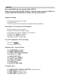
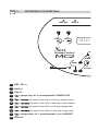
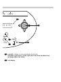
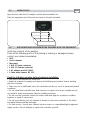
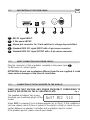
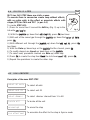
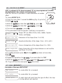
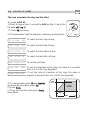
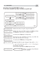
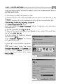
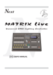
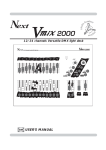
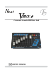
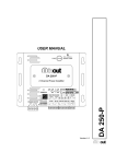
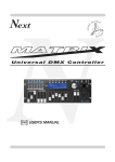
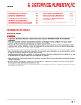
Next
Moving Control
GB
USER’S MANUAL
INDEX
We congratulate you on your purchase of MC2.
Before you proceed using this product, read this user’s manual carefully, as
it gives important information on safety, use and maintenance .
Equipment Setting
1.1 Description of the front panel
1.2 Unpack MC2
1.3 Acessories and documentation provided with the equipment
Description of the rear panel and installation
2.1
2.2
2.3
2.4
2.5
2.6
Description of the rear panel
Input connection for power supply
Connection of the AC adapter to the main AC
DMX 512 Output connection
DMX 512 Input connection
Making a DMX 512 signal cable
Use of the equipment - Start Up setting
3.1 Use of Joystick
3.2 First use of the unit
Equipment Use - menu functions
4.1 LOAD UNITS from library
4.2 MENU: DEFINE UNITS
4.3 MENU: EDIT DMX CHANNELS
4.4 Creation of a STEP
4.5 MENU: EDIT STEP
4.6 Creation of an EFFECT
4.7 MENU: EDIT EFFECT
4.8 Creation of a LOOP
4.9 MAIN MENU
4.10 RS 232 HOST LINK
Schematic menu
5.1
5.2
5.3
5.4
DEFINE UNITS+SPECIAL FUNCTION schematic menu
EDIT STEP schematic menu
EDIT EFFECT schematic menu
EDIT LOOP schematic menu
GB 1.1
1.1 DESCRIZIONE
DESCRIPTION
PANNELLO
OF THECOMANDI
FRONT PANEL
DMX OUT
1
✔
Edit
DMX IN
2
Back
Ok
➥
l01 st:
Next
Moving Control
MC2
Step
Rate
6
3
Channe
4
1
Edit / Ok key
2
Back key
3
Step led
4
Key to change step, for 2 second pressed it CHANGE LOOP
5
Key to increase the speed of the step/in edit step change channel
6
Key to decrease the speed of the step/in edit step change channel
7
Key to increase the speed of the effect/in edit step change value
8
Key to decrease the speed of the effect/in edit step change value
9
Key to change effect, for 2 second pressed activate BLACKOUT
10
Effect led
5
-SW
9 VDC IN
12
01 ef:01
11
Speed
7
Effect
10
Value
8
9
11
Joystick: it allows an easy positioning of the unit.
Up/down scroll menu, on the right select the item visualized and
up/down adjust the values.
12
Lcd display
1.2
UNPACK MC2
GB
Open the box; take the AC adapter and the documentation out.
Take the equipment out of the box as shown in the picture below.
1.3
ACESSORIES AND DOCUMENTATION PROVIDED WITH THE EQUIPMENT
Verify the contents of the packing.
If one of the following parts of the packing is missing or damaged, please,
contact your dealer immediately.
•
•
•
•
•
•
•
MC2
User’s manual.
Warranty
1 XLR 5 P male connector
1 XLR 5 P female connector
1 AC adapter mod.1814807
1 Cable male/female RS 232
Read the following warnings before beginning installation.
• This unit is not intended for home use.
• Read this manual thoroughly and observe the following precautions before working
with the controller.
• Take care not to spill liquids on to the controller and do not use it in excessively humid
conditions.
• Do not install the controller near heat sources or expose it to direct sunlight and do
not install in dusty environments without suitable protection.
• Do not use the controller unless the mains cable and plug are in perfect condition
(replace or repair if necessary).
• Do not use solvents such as acetone or alcohol to clean the controller or the finish
and panel lettering will be damaged.
• If a fault occurs, consult your nearest service centre or a specialized light equipment
repair service. Do not attempt to repair the controller yourself.
2.1
GB
DESCRIPTION OF THE REAR PANEL
PUSH
5
4
1
3
2
5
4
1
3
2
F
1
2
3
4
5
1
RS232 signal INPUT.
2
9 Vdc power INPUT.
3
Stereo jack connector for 2 foot-switches to change step and effect
4
Standard DMX 512 signal INPUT with a 5-pin cannon connector.
5
Standard DMX 512 signal OUTPUT with a 5-pin cannon connector.
2.2
INPUT CONNECTION FOR POWER SUPPLY
Plug the connector of the ac-adapter completly in the power input 2
To disconnect it, extract gently.
ATTENTION: do not use ac-adapters different from the one supplied, it could
cause serious damages at the internal circuitation.
2.3
CONNECTION OF THE AC-ADAPTER TO THE MAIN AC
MAKE SURE THAT VOLTAGE AND POWER FREQUENCY CORRESPOND TO
WHAT IS REPORTED ON THE AC ADAPTER PLATE.
Fig. 1
The supplied ac-adapter has a plug,
therefore you should only plug it in the
socket.
NeXT MC2 V1.0
When MC2 is powered, the lcd display appears as in (Fig.1), if this condition is
not true, please check if there is power in the electric socket or check the connection between ac-adapter/controller and ac-adapter/electric socket.
If the problem persist, please consult your dealer.
2.4
GB
DMX 512 OUTPUT CONNECTION
Make sure you are using shielded twisted cables suitable for the transmission of the
DMX 512 signal with connectors of good quality.
Plug the 5-pin XLR connector coming from the unit completly in the DMX 512 output
5
Use the “push” safety hook to disconnect it and than extract it gently.
ATTENTION: the shielded part of the cable must never be connected to the ground of
the electrical system as this could cause faults during the working of the controller
2.5
DMX 512 INPUT CONNECTION
Plug the 5-pin XLR connector coming from the light desck completly in the DMX 512
output 4
You can control the channels of the units through the fader of the light desk.
When you edit units the first 48 channels come acquired from the connected light desk
The PAN and TILT channels are controlled through joystick of the MC2.
In the normal operation (without light desk connected) the first 48 channels are passing
and could be used like dimmer channels.
The unitis must depart from address 49.
2.6
MAKING A DMX 512 SIGNAL CABLE
MC2 has a DMX 512 input/output that uses standard XLR 5-pin connector
The connection must be done with cable shielded by these characteristics:
-
2 conductors plus screen
120 Ohm impedance
low capacity
maximum transmission rate 250 Kbaud.
XLR 5-pin
5
1
4
2
3
For the connection do reference to the figure.
Common
- DMX OUT
+ DMX OUT
3.1
USE OF THE JOYSTICK
GB
The joystick of the MC2 has more functions (Fig. 8)
Up/down: Scroll the menu
Right : Select the menu
Up/down: Regulate the values
Right : OK
Using the joystick the PAN and TILT channels of
the scanner’s mirror and moving heads can be
adjusted.
The joystick type is with central return, thanks to
the sophisticated software of management, it
allows an easy and exact positioning.
If you leave the joystick in central position the
mirror keeps still; whereas the more you move it
away from the centre the faster the mirror will
run.
3.2
FIRST USE OF THE UNIT
MC2 is a universal DMX controller and is provided with an initial generic configuration.
For a correct operation YOU MUST configure the controller with the type of projectors/scanner connected to it. (see.par.4.1)
The SETUP LIBRARY sheet includes the list of the projectors/scanner contained in
the internal memory of the controller, if the requested configuration is not present
in the library, you need to make a personalized one. (see.par.4.3)
4.1
LOAD UNITS FROM LIBRARY
GB
To activate the function LOAD FROM LIBRARY:
1) Press for more than 2 second the Edit key (Fig. 2) up to the lcd
write edit loop 01
2) With the joystick up/down find DEFINE UNITS , press Ok
✔
Edit
3) The lcd write No OF UNITS : xx , press Ok
Ok
Fig. 2
4) With the joystick up/down set the connected units, press Ok.
5) With unit of the same type through the joystick up/down find edit all UNITS then
press Ok
6) With different unit through the joystick up/down find edit unit 01 then press Ok two
times..
7) The lcd shows the name of the projector currently in use
8) With the joystick down find load from lib. press Ok, the lcd shows the name of the
first projector contained in the memory
9) With the Speed up/down keys or the joystick choose the unit that corresponds to
the model in use, to search in alphabetical sequence use Rate up/down keys
10) Press OK to store in memory the fixture
11) Press Back the lcd write save ? YES press Ok.
12) With different unit repeat the operations from the point 7, through the joystick
up/down change unit and press Ok at the end press Back
13) With the joystick up/down find patch UNITS
14) The lcd write auto patch! press Ok.
15) With the joystick up/down check the assigned values . The first unit departs from
address 49, MC2 will calculate the last channel for that unit and the lcd write the configuration to set on the unit.
16) To modify the address press Ok
17) With the joystick up/down set the new address then press Ok
18) To go out from the menu press Back more times
4.2
MENU: DEFINE UNITS
Description of the menu DEFINE UNIT
n o . of units 01
To set how much unit are present, from 01 to 20 max
edit all units
To modify the fixture of all the present units and load from
library
edit unit 01
To modify the fixture of 1 unit and load from library
patch units
To patch unit automatic or manually
4.3
MENU: EDIT DMX CHANNELS
GB
This function allows to modify manually the name of each channel and its
parameters (reset value, blackout value) it also allows to assign special
functions to the channel (pan/tilt,pan low/tilt low, lamp control dmx in).
ATTENTION ! MODIFICATION OF THE SETUP PARAMETERS, IF NOT EFFECTED
IN AN APPROPRIATE WAY, PREVENTS THE CONNECTED UNIT TO WORK
CORRECTLY.
To activate this function you need to repeat the operations up to the point 7, in
the MENU DEFINE UNIT functions (v.par.4.1), and after the lcd shows the
name of the unit previously loaded.
To modify unit name:
1) Press Ok
2) To modify the first letter of the unit use the joystick up/down
3) To modify the second letter of the unit use the joystick right at the end press Ok
To modify the number of the channels
1) With the joystick up/down find max channel: xx
2) Press Ok
3) With the joystick up/down set the channels (max 48)
To modify the name of the channels
1) With the joystick up/down find ch01 : xxxx
2) Press Ok
3) With the Speed up/down keys or the joystick choose the name to change,
to search in alphabetical sequence use Rate up/down keys then press Ok
4) Repeat the operation for the other channels
The controller uses these special channels for predefined functions, you must use
them for the specific functions assigned to them.
NOT USED -> Not used channel.
PAN
-> Pan channel (SOFT CROSS/HARD CROSS).
PAN LOW -> Pan channel LOW.
TILT
-> Tilt channel (SOFT CROSS/HARD CROSS).
TILT LOW -> Tilt channel LOW.
LAMP
-> Lamp control channel.
LAMP/RES -> Like LAMP.
DMX-IN -> Control channel for external light desk
Only if the LAMP or LAMP/RES channel is selected; press OK to modify LAMP ON
value. Press OK again to modify LAMP OFF value.
4.4
GB
CREATION OF A STEP
MC2 has 340 STEP these are static scenes.
To execute them in succession create Loop without effects,
with no active units in the effect or associate effects with
shape (OFF) for PAN and TILT. (v.par 4.6)
To create STEP 001:
1) Press for more than 2 second the Edit key (Fig. 3) up to the
lcd write edit loop 01
✔
Edit
Ok
Fig. 3
2) With the joystick up/down find edit step 0 01 , press Ok two times
3) With unit of the same type through the joystick up/down find select all UNITS,
press Ok
4) With different unit through the joystick up/down find edit unit 01 , press Ok
two times
5) With the Rate up/down keys or the joystick find the channel, press Ok
6) To modify channel use Speed up/down keys or the joystick
7) To select next/precedent channels use Rate up/down keys
8) Press Ok to create the step then Back the lcd shows save ? YES , press Ok.
9) Repeat the operations to create the other step
4.5
MENU: EDIT STEP
Description of the menu EDIT STEP
select all units
To select all units
select unit 01
To select unit 01
select dimmers
To select dimmer channel from 1 to 48
locate all!
To locate all the unit
erase step!
To erase the step
run effect : next
To associate the effect to the step in Syncro mode
4.6
GB
CREATION OF AN EFFECT
MC2 is endowed of 96 plays movement 12 are pre-programmed, (modifiable) dedicated to the scanner and moving-head
With this function it’s possible to create animations of notable
effect.
Edit
To create EFFECT 013:
1) Press for more than 2 second the Edit key (Fig. 4) up to the
lcd write edit loop 01
✔
Ok
2) With the joystick up/down find edit EFFECT 01 , press Ok
3) With the joystick up/down find
Fig. 4
edit EFFECT 13 , press Ok
4) The lcd shows pan motion , press Ok
5) The parameters that the operator could vary correspond to:
shape
><off><
Shape: OFF (no effect) Circle, Hola, Ladder, Square,
Vertex, and Zigzag
figure size 020
Dimension of the shape (from 1 to 128)
speed (rpm)
Speed and direction of the shape ( from -60 to +60)
15
phase angle 000
Corner of departure of the shape (from 0 to 359).
delay angle 015
Delay of execution of the shape between an unit and the
next (from 0 to 359).
6) To modify parameter press Ok with the joystick up/down set new value,
press Ok
7) Press Back
8) Repeat the operations for tilt motion if you want effect for TILT
9) With the joystick up/down find active unis! press Ok select all! press Ok
10) To go out from the menu press Back more times
4.7
MENU: EDIT EFFECT
Description of the menu EDIT EFFECT
pan motion
To create effect for x movment
tilt motion
To create effect for y movment
active units
To select what unit must have the type of effect, the step
is in stop without unit selected
4.8
GB
CREATION OF A LOOP
The Loop assembles the step and the effect
To create LOOP 01:
1) Press for more than 2 second the Edit key (Fig. 5) up to the
lcd write edit loop 01
✔
Edit
Ok
2) Press Ok two times..
3) The parameters that the operator could vary correspond to:
first step
001
To select the first step of loop
last step
001
To select the last step of loop
Fig. 5
first effect 01
To select the first effect of loop
last effect 12
To select the last effect of loop
next loop is 02
To set the next loop
step time
002 S
To set the total time of the step, the value is in seconds
from 0,2 to 600, (see fig.under)
step fade 050%
To set the time of transition of the step, the value is
express in percent from 0 to 100%, (see fig.under)
4) To change value press Ok with joystick
up/down set new value, press Ok
5) Press Back
6) To go out from the menu press Back
more times
STEP
value
STEP
FADE
TIME
4.9
GB
MAIN MENU
Description of the menu MAIN MENU see fig. 6
To run menu use joystick up/down, to modify use joystick right.
l01 st : 001 ef : 10
rt : 100% sp : 100%
go to loop 02
go to loop 02
go to loop 01
go to loop 01
go to loop 96
go to loop 96
step : single
step : loop run
effect : free run
effect : syncro
Fig. 6
l01 st : 001 ef : 10
Indicate the state of loop 01 step 001 effect 10
rt : 100% sp : 100%
Indicate the step and effect speed, use Rate up/down
and Speed up/down keys to change the values
step : single
You must press Step key to change step
step : loop run
Executes the step specified in the loop, one after the
other with the times set in the loop
effect : free run
You must press Effect key to change effect
effect : syncro
Change the effect to each change of step, with run effect
next go to the next step, with run effect 01 the step is
associated to the effect.
In this mode of operation the Effect key also works
l01 st : 001 ef : 10
go to loop 01
Allows to change loop between
the 96 available
4.10
GB
RS 232 HOST LINK
THIS FUNCTION ALLOWS TO UPDATE LIBRARY, SAVE THE PROGRAMMING AND TO
RESTORE USER DATA.
1) Disconnect the DMX and power in cable.
2) Connect the RS 232 cable (included) from the MC2 to the RS 232 of the
Computer
3) Start a program of terminal emulation and to set the communication like:
115200 bps, 8 data bit, no parity, 1 stop bit.
With Miicrosoft Windows® system
start the software H y p e r T e r m i n a l (Start> Programs> Accessories>
Communications
4) Set the connection like in fig. 7 - 8 - 9
5) Press at the same time Rate up and Speed up then connect the power plug,
the lcd write RS232 HOST LNK!
5) In the monitor of Computer appears
the Menù see fig.10
Computer Keyboard) the number
Press (C
of the desired function.
6) Press 1 to save the data of programming;
You must select from the menù
Transfer> Receive file. Set Ymodem protocol then click to Receive The saved file
is in the Hard Disk with name
mc2_set.bak
Fig. 7
Fig. 8
7) Press 2 to restor the data of
programming;
You must select from the menù
T r a n s f e r > S e n d f i l e . search the
file with mc2_set.bak name, set
Y m o d e m protocol then click to
Send.
8 ) Press 3 t o u p d a t e s e t u p
library; you must select from the
file menù T r a n s f e r > S e n d f i l e .
search the file with m c 2 _ l i b . b i n
name (downloaded from internet),
set Ymodem protocol then click to
Send see fig.11
9) Press 4 to exit.
Close the application and disconnect the cable.
Fig. 9
Fig. 10
Fig. 11
edit loop 01
patch units
auto patch!
edit step 001
edit effect 01
define u nits
n o . of units 01
OK
auto patch! done
unit 01 dmx (49)
unit 02 dmx (66)
OK
unit 02 dmx (66)
no. of units 02
OK
no. of units 02
unit 02 dmx (65)
unit 02 dmx (65)
OK
unit 02 dmx (65)
no. of units 01
OK
no. of units 01
unit 03 dmx (81
unit 02 dmx (64)
OK
unit 02 dmx (64)
no. of units 20
OK
no. of units 20
edit all units
dts xr250 wash
OK
ets xr250 wash
OK
ets xr250 wash
dts xr250 wash
OK
dts xr250 wash
ctt xr250 wash
OK
ctt xr250 wash
cts xr250 wash
cts xr250 wash
OK
cts xr250 wash
ctr xr250 wash
OK
ctr xr250 wash
cts xr250 wash
edit unit 02
abs clublive
OK
abs clublive
abs clubcolor
OK
abs clubcolor
std dimmer 48ch
OK
std dimmer 48ch
max channel: 48
OK
max channel: 48
max channel: 16
OK
max channel: 16
max channel: 15
OK
max channel: 15
ch01:Pan low
OK
ch01:Pan low
ch01:Pan
ch01:Pan
OK
ch01:Pan
ch02:Pan low
ch01:Palette
OK
ch01:Palette
edit unit 01
edit unit 01
load from lib.
edit unit 20
max channel: 16
special f unction
reset units!
OK
reset units! done
lamps on!
OK
lamps on! done
lamps off!
OK
lamps off! done
ch03:tilt
ch04:tilt low
5.1
SCHEMATIC MENU: DEFINE UNITS+ SP. F.
chxx: xxxxxx
11 zoom
edit loop 01
edit step 002
edit s tep 0 01
edit step 001
edit effect 01
edit step 340
select all units
define units
000
11 zoom
255
11 zoom
255
11 zoom
000
11 zoom
000
pan tilt 255, 127
pan tilt 000, 110
01 dimmer
01 dimmer
255
01 dimmer
255
01 dimmer
000
01 dimmer
000
DIMMER (48)
255
DIMMER (48)
255
DIMMER (48)
050
DIMMER (48)
050
DIMMER (48)
000
DIMMER (48)
000
DIMMER (01)
050
DIMMER (01)
050
DIMMER (02)
255
DIMMER (48)
255
DIMMER (02)
050
DIMMER (48)
050
DIMMER (02)
000
DIMMER (48)
000
255
special function
OK
pan tilt 000, 110
select unit 01
DIMMER (48)
select dimmers
DIMMER (01)
DIMMER (02)
SCHEMATIC MENU: EDIT STEP
050
050
locate all!
OK
locate all! DONE
erase step!
OK
erase step! DONE
run effect : next
5.2
050
run effect : 01
run effect : 01
run effect : next
run effect : next
run effect : 96
run effect : 96
edit loop 01
edit step 001
edit effect 02
edit e ffect 0 1
edit effect 01
define units
pan motion
shape
><off><
figure size 128
figure size 128
figure size 020
figure size 020
figure size 019
figure size 019
edit effect 96
figure size 020
special function
shape
><off><
shape
zigzag
shape
vertex
shape
square
tilt motion
speed (rpm)
15
phase angle 000
60
shape
ladder
speed (rpm)
15
speed (rpm)
15
shape
hola
speed (rpm)
60
speed (rpm)
60
shape
circle
phase angle 000
phase angle 000
phase angle 359
phase angle 359
delay angle 016
delay angle 016
delay angle 015
delay angle 015
delay angle 359
delay angle 359
Back
➥
unit 01
no
unit 02
no
unit 02
yes
unit xx
yes
unit xx
no
l01 st:
yes
DMX IN
select all! done
DMX OUT
Ok
✔
Next
Edit
phase angle 001
Moving Control
phase angle 001
Rate
SCHEMATIC MENU: EDIT EFFECT
OK
speed (rpm)
unit 01
Channe
5.3
select all!
Step
active units
60
MC2
delay angle 015
speed (rpm)
002
first step
002
first step
001
first step
001
first step
340
first step
340
last step
002
last step
002
last step
001
last step
001
last step
340
last step
340
edit effect 01
last step
special function
Effect
define units
001
first effect 01
last effect 12
next loop is 02
step time
5.4
SCHEMATIC MENU: EDIT LOOP
002 S
step fade 050%
first effect 02
first effect 02
first effect 01
first effect 01
first effect 96
first effect 96
last effect 13
last effect 13
last effect 12
last effect 12
last effect 11
last effect 11
next loop is 03
next loop is 03
next loop is 02
next loop is 02
next loop is 01
next loop is 01
step time
003 S
step time
003 S
step time
002 S
step time
002 S
step time
001 S
step time
001 S
step fade 051%
step fade 051%
step fade 050%
step fade 050%
step fade 049%
step fade 049%
9 VDC IN
edit loop 96
001
first step
-SW
edit step 001
first step
01 ef:01
edit loop 01
Speed
edit l oop 0 1
Value
edit loop 02
MC2 TECHNICAL FEATURES
• Individual control of up to 20 DMX 512 units.
• 48 DMX channels for each unit.
• 512 DMX configurable channels for intelligent units and dimmers, 48 channels
(maximum) for dimmers.
• 340 programmable steps
• 96 Built in editable effects for PAN and TILT 8/16 bit.
• 96 programmable loops for step and effect sequences.
• RS-232 for connection with a PC.
• DMX 512/1990 standard output (5-pin female “XLR” connector).
• Display LCD.
• Ability to use an external DMX controller for Edit and Live functions.
• Compatible with every DMX 512 unit (max 48 channels)
- Programmable channels name and function.
Climatic condition for the use
• Umidità: 35% ÷ 80%
• Temperatura: -10° ÷ +50 °C
Dimensions and weight
Dimension (W x L x H) / Weight: 287 x 132 x 40 mm (4U rack) / 2 Kg.
Note
CODEM MUSIC S.r.l. - Via G.Pierini, 13 - 61100 PESARO - ITALY
Tel. +39 0721 204357 - Fax +39 0721 203554
http://www.codemmusic.com - E-mail: [email protected]
All rights reserved. No parts of this document can be copied, photocopied or reproduced without the
prior written permission of the CODEM MUSIC s.r.l.
No responibility is taken for possible inaccuracies or mistakes.
The CODEM MUSIC s.r.l. reserves the right to make any alterations or aesthetics changes of this
product that seem necessary at any time and for whatever reason.
The CODEM MUSIC s.r.l. takes no responsibility for the use or for the application of this product.
GB