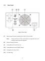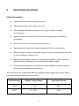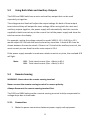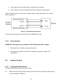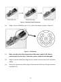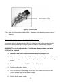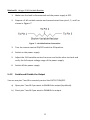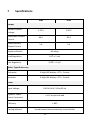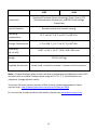
1
Model 1693, 1694
Switching DC Power Supply
INSTRUCTION MANUAL
1
Safety Summary
The following safety precautions apply to both operating and maintenance personnel and
must be observed during all phases of operation, service, and repair of this instrument. Before
applying power, follow the installation instructions and become familiar with the operating
instructions for this instrument.
GROUND THE INSTRUMENT
To minimize shock hazard, the instrument chassis and cabinet must be connected to
an electrical ground. This instrument is grounded through the ground conductor of
the supplied, three-conductor ac power cable. The power cable must be plugged
into an approved three-conductor electrical outlet. Do not alter the ground
connection. Without the protective ground connection, all accessible conductive
parts (including control knobs) can render an electric shock. The power jack and
mating plug of the power cable meet IEC safety standards.
DO NOT OPERATE IN AN EXPLOSIVE ATMOSPHERE
Do not operate the instrument in the presence of flammable gases or fumes.
Operation of any electrical instrument in such an environment constitutes a definite
safety hazard.
KEEP AWAY FROM LIVE CIRCUITS
Instrument covers must not be removed by operating personnel. Component
replacement and internal adjustments must be made by qualified maintenance
personnel. Disconnect the power cord before removing the instrument covers and
replacing components. Under certain conditions, even with the power cable
removed, dangerous voltages may exist. To avoid injuries, always disconnect power
and discharge circuits before touching them.
DO NOT SERVICE OR ADJUST ALONE
Do not attempt any internal service or adjustment unless another person, capable of
rendering first aid and resuscitation, is present.
DO NOT SUBSTITUTE PARTS OR MODIFY THE INSTRUMENT
Do not install substitute parts or perform any unauthorized modifications to this
instrument. Return the instrument to B&K Precision for service and repair to ensure
that safety features are maintained.
1
WARNINGS AND CAUTIONS
WARNING and CAUTION statements, such as the following examples, denote a
hazard and appear throughout this manual. Follow all instructions contained in
these statements.
A WARNING statement calls attention to an operating procedure, practice, or
condition, which, if not followed correctly, could result in injury or death to
personnel.
A CAUTION statement calls attention to an operating procedure, practice, or
condition, which, if not followed correctly, could result in damage to or destruction
of parts or the entire product.
WARNING:
Do not alter the ground connection. Without the protective ground
connection, all accessible conductive parts (including control knobs)
can render an electric shock. The power jack and mating plug of the
power cable meet IEC safety standards.
WARNING:
To avoid electrical shock hazard, disconnect power cord before
removing covers. Refer servicing to qualified personnel.
CAUTION:
Before connecting the line cord to the AC mains, check the rear panel
AC line voltage indicator. Applying a line voltage other than the
indicated voltage can destroy the AC line fuses. For continued fire
protection, replace fuses only with those of the specified voltage and
current ratings.
CAUTION:
This product uses components which can be damaged by electrostatic discharge (ESD). To avoid damage, be sure to follow proper
procedures for handling, storing and transporting parts and
subassemblies which contain ESD-sensitive components.
SAFETY SYMBOLS
This symbol on an instrument indicates that the user should refer to the
operating instructions located in the manual.
Certification
We certify that this product met its published specifications at time of shipment from the
factory.
2
Compliance Statements
Disposal of Old Electrical & Electronic Equipment (Applicable in the European Union and
other European countries with separate collection systems)
This product is subject to Directive 2002/96/EC of the European
Parliament and the Council of the European Union on waste
electrical and electronic equipment (WEEE), and in jurisdictions
adopting that Directive, is marked as being put on the market
after August 13, 2005, and should not be disposed of as
unsorted municipal waste. Please utilize your local WEEE
collection facilities in the disposition of this product and
otherwise observe all applicable requirements.
3
Contents
1
2
3
Safety Summary ........................................................................................ 1
Introduction .............................................................................................. 5
Installation ................................................................................................ 6
3.1
Initial Inspection................................................................................ 6
3.2
Input Power Requirements ............................................................... 6
4
Controls and Indicators ............................................................................. 7
4.1
Front Panel ........................................................................................ 7
4.2
Rear Panel ......................................................................................... 8
5
Operating Instructions .............................................................................. 9
5.1
Instrument Hook-Up ....................................................................... 10
5.2
Using Both Main and Auxiliary Outputs .......................................... 11
5.3
Remote Sensing............................................................................... 11
5.3.1
Connection .............................................................................. 11
5.3.2
Disconnection.......................................................................... 12
5.4
Remote Control ............................................................................... 12
5.4.1
Voltage Remote Control.......................................................... 12
5.4.2
Enable and Disable the Output ............................................... 15
6
Maintenance ........................................................................................... 16
6.1
When the Unit is Not Turning On ................................................... 16
6.2
Fuse Replacement ........................................................................... 16
6.3
Instrument Repair Service............................................................... 17
7
Specifications .......................................................................................... 18
8
Certification ............................................................................................ 20
9
Service Information ................................................................................ 21
10 Limited One-Year Warranty .................................................................... 22
4
2
Introduction
B&K Precision models 1693 and 1694 switching mode DC power supplies provide
high current output in a lightweight and compact package. It is suitable for a variety
of uses, especially for powering DC operated mobile radio equipment on the bench.
These 900W power supplies provide a variable voltage output from 1 V to 15 V at 60
A (model 1693) or from 1 V to 30 V at 30 A (model 1694). In addition, a remote
sensing terminal is available for use to compensate for voltage drops due to
resistances from load leads. The output voltage level can also be externally controlled
via an analog remote control terminal. Switching mode power supplies have the
advantage of being lightweight and high in efficiency when compared to traditional
linear mode power supplies. The efficiency can exceed 85% under optimal conditions.
Bright 3-digit LED displays give an accurate and highly readable indication of settings.
Features
• Up to 60 A output current
• Lightweight and compact
• Dual 3-digit LED displays
• Remote sense terminal
• Analog remote control via external voltage source or variable resistor
• Current foldback circuitry with illuminated indicator prevents overloading
the power supply
• Overtemperature protection circuitry
• Overvoltage protection
• Front panel auxiliary output
5
3
3.1
Installation
Initial Inspection
This unit is tested prior to shipment. It is therefore ready for immediate use upon
receipt. The initial physical inspections should be made to ensure that no damage has
been sustained during shipment.
Inspect the packing box on receipt for any external damage. If any external damage is
evident, remove the instrument and visually inspect its case and parts for any
damage. If damage to the instrument is evident, a description of the damage should
be noted on the carrier’s receipt and signed by the driver or carrier agent. Save all
shipping packaging for inspection. Forward a report of any damage to the agent
through which the unit is procured.
Retain the original packing in case subsequent repackaging for return is required. Use
of the original packing is essential.
After the mechanical inspection, verify the contents of the shipment. The items
included with the instrument are:
• Power cord
• Instruction manual
• Remote control connector
If the contents are incomplete, or if the instrument does not pass the specification
acceptance tests, notify the local service center.
3.2
Input Power Requirements
The power supply has a universal input and can operate in any country that uses a
mains voltage within 100-240 VAC, 50Hz/60Hz.
6
4
Controls and Indicators
4.1
Front Panel
Figure 1 - Front Panel
(1)
Voltage and Ammeter LED Display
(2)
Overload LED Indicator – Overload (Constant Current Limiting) and ShortCircuit Protection
(3)
Output Voltage Control Knob – Control Both Main and Auxiliary Output
(4)
Power ON/OFF Switch
(5)
Power ON/OFF LED
(6)
Auxiliary Output Terminal (max 5 A for 1693, max 3 A for 1694)
Note:
Please see Section 5.2 for more details on using both main and
auxiliary output terminals together.
7
4.2
Rear Panel
Figure 2 - Rear Panel
(7)
Main Output Terminal (rated 60 A for 1693 / 30 A for 1694)
Note:
Please see Section 5.2 for more details on using both main and
auxiliary output terminals together.
(8)
Remote Sensing Terminal
(9)
Analog Remote Control Terminal
(10)
Analog Remote Control ON/OFF Switch
(11)
Cooling Fan Air Intake Grille
(12)
AC Input Plug
8
5
Operating Instructions
Safety Precautions
●
Never short the remote sensing terminal.
●
This power supply is for indoor use only.
●
Do not expose the power supply to sun, high humidity, or dusty
environments.
●
Never remove the metal cover of the power supply while AC power is
connected.
●
Never touch the unit when your hands are wet.
●
Never block the ventilation slots and cooling fan air intake window.
●
Never attempt to repair the power supply. Incorrect reassembly may result
in a risk of electric shock or fire.
●
Never use the power supply for a load requiring higher current than the
designed value, otherwise it may damage the power supply.
●
Place the power supply on a flat surface with sufficient clearance and dry,
dust-free surroundings for ventilation.
This series has two models with different output voltage range and current. Make
sure you have purchased the correct one.
Model Number
Output Voltage Range
Total Rated Current
1693
1 – 15 V
60 A
1694
1 – 30 V
30 A
Table 1 - Models
9
5.1
1.
Instrument Hook-Up
Check the rating label of the power supply and make sure it complies with your
AC mains voltage. Connect the power supply to the AC mains using the provided
power cord.
CAUTION: The AC input is double pole fusing.
2.
If you do not use the analog remote control feature, make sure the remote
control ON/OFF switch on the rear panel is in the OFF position. For analog
remote control procedures, please refer to Section 5.4.
3.
Switch on the power supply and the power ON/OFF LED should light up in green.
Then, adjust the output voltage to the desired voltage and switch off the power
supply.
4.
If you are using remote sense, connect as described in Section 5.3. Otherwise,
skip to the next step.
5.
Connect the positive polarity of the device being powered to the red (+) terminal
of the power supply.
6.
Connect the negative polarity of the device being powered to the black (-)
terminal of the power supply.
7.
Switch on the power supply first and the LED indicator should light up in green.
8.
Switch on the equipment and the LED indicator should still remain green.
9.
You can now operate the equipment. When an operation is finished, switch off
the equipment first and then switch off the power supply.
10. When disconnecting the power supply from the unit, disconnect the remote
sensing wire first, and then disconnect the output cables.
Note: Steps 2 and 4 explain how to use the special features – analog remote control
and remote sense. You can use both features at the same time or separately.
10
5.2
Using Both Main and Auxiliary Outputs
The 1693 and 1694 both have a main and auxiliary output that can be used
separately or together.
The voltage control knob will adjust the output voltage for both of these output
terminals and they will output the same voltage. When using both the main and
auxiliary outputs together, the power supply will automatically total the currents
supplied to both terminals up to the current limit of the power supply and show the
total current on the display.
For example, setting the voltage output for model 1693 (1-15 V, 0-60 A) to 15 V
would output 15 V at both the main and auxiliary terminals. A total of 60 A can be
drawn between the two terminals. If there is a 5 A load at the auxiliary terminal, the
most current you can draw from the main output is 55 A.
If the power supply exceeds its maximum rated current at any time, the overload LED
will light.
Note:
5.3
1693 - Total rated current (Aux. + Main) is 60 A
1694 - Total rated current (Aux. + Main) is 30 A
Remote Sensing
WARNING: Never short the remote sensing terminal.
Never connect the remote sensing terminal in reverse polarity.
Always disconnect the remote sensing terminal first.
The 1693 and 1694 both provide a remote sensing terminal to help compensate for
voltage drops due to load leads.
5.3.1
Connection
1. Make the power connections between power supply and equipment.
11
2. Check and make sure the power connections are secure.
3. Then make connections between Remote Sensing and equipment.
Figure 3 shows typical connection between power supply and device for remote
sense operation.
Figure 3 - Remote Sense Connection
The remote sensing wire should be at least 22AWG wire size.
5.3.2
Disconnection
WARNING: Wrong disconnect sequence will damage the power supply.
1. Disconnect the remote sensing connections.
2. Disconnect the power connections between the power supply and
equipment.
5.4
Remote Control
5.4.1
Voltage Remote Control
Set up the provided remote connector plug.
(a)
Remove the pin plug of the remote control connector plug by removing the
screw as shown in Figure 4.
12
Figure 4 - Remote Control Connector
(b)
Solder 3 wires (22AWG) to pins 1, 2, and 3 of pin plug as shown in Figure 5.
Figure 5 - Pin Numbers
(c)
Make sure the load is disconnected and the power supply is OFF before
continuing to the next step. Otherwise, power supply may be damaged.
(d)
Plug the remote connector plug into the remote control terminal of the power
supply.
(e)
Secure the remote connector plug to the terminal socket by locking connector
ring (Figure 6).
13
Figure 6 - Connector Ring
Then, you can choose either method A or B below to use the analog remote control
feature.
Method A: Using an External Variable DC Voltage Source
A variable external voltage source of 0 to 5 V is fed into the analog remote control
terminal to adjust the output voltage level of both Main and Auxiliary outputs.
WARNING: Do not input higher than 5 V, otherwise the overvoltage protection
(OVP) will be triggered.
1. Make sure the load is disconnected and the power supply is OFF.
2. Only use wires from pins 2 and 3. Connect pin 2 to positive polarity of the
external voltage source and pin 3 to negative polarity of the external voltage
source.
3. Turn the remote control ON/OFF switch to ON position.
4. Switch on the power supply.
5. Vary the external input voltage from 0 to 5 V to check and verify the full
output voltage range of the power supply.
6. Switch off the power supply.
14
Method B: Using a 5 kΩ Variable Resistor
1. Make sure the load is disconnected and the power supply is OFF.
2. Prepare a 5 kΩ variable resistor and connect wires from pins 1, 2, and 3 as
shown in Figure 7.
Figure 7 - Variable Resistor Connection
3. Turn the remote control ON/OFF switch to ON position.
4. Switch on the power supply.
5. Adjust the 5 kΩ variable resistor from one end to the other to check and
verify the full output voltage range of the power supply.
6. Switch off the power supply.
5.4.2
Enable and Disable the Output
You can use pins 7 and 8 to remotely control the OUTPUT ON/OFF.
a) Open pins 7 and 8 if you want to ENABLE the output (by default).
b) Short pins 7 and 8 if you want to DISABLE the output.
15
6
6.1
Maintenance
When the Unit is Not Turning On
Check if the power ON/OFF switch is turned ON. If not, then check the power cord.
Please make sure that the power cord is properly connected to the unit. Please also
check the main switch and ensure that the AC supply at your site is the same as the
one mentioned at the rear chassis of the unit. Check for a blown fuse.
6.2
Fuse Replacement
If the fuse blows, the LED will not light and the instrument will not operate. Replace
only with the correct value fuse. Refer to table below for fuse value and type. There
are two identical fuses located internally on a PCB near the power input receptacle.
Line Voltage
Fuse
Type
100 – 240 VAC
20 A/250 V
3AB ceramic tube fast blow
Table 2 - Fuse Table
CAUTION: Never remove the metal cover of the power supply while AC power is
connected.
Replace fuses as follows:
1. Unplug the power cord from the rear of the instrument.
2. Use a screwdriver to remove case cover of power supply.
3. Locate PCB near the power input receptacle where the fuses are clipped in
(designated as F1 and F2) and replace blown fuses.
16
Figure 8 - Fuse Location
6.3
Instrument Repair Service
Because of the specialized skills and test equipment required for instrument repair
and calibration, many customers prefer to rely upon B&K Precision for this service.
We maintain a network of B&K Precision authorized service agencies for this
purpose. To use this service, even if the instrument is no longer under warranty,
follow the instructions given in the Warranty Service section of this manual. There is
a nominal charge for instruments out of warranty.
17
7
Specifications
1693
1694
1-15 V
1-30 V
Rated Main Output
Current
60 A
30 A
Rated Auxiliary
Output Current
5A
3A
Output
Variable Output
Voltage
Ripple and Noise
40 mVpp
Load Regulation
0.1% + 5 mV
Line Regulation
0.05% + 3 mV
Meter Type & Accuracy
Voltmeter
3-digit LED display ± 1% + 1 count
Ammeter
3-digit LED display ± 1% + 1 count
Other
Input Voltage
Dynamic Power
Factor Correction
100-240 VAC, 50 Hz/60 Hz
> 0.97 at optimal load
Efficiency
Cooling Method
> 85%
Variable speed thermostatically controlled fan
18
1693
Protections
Special Features
1694
Overload (Constant Current Limiting), Short Circuit, OTP
(Overtemperature Protection), and OVP (Overvoltage
Protection)
Remote control and remote sensing
Operating
Temperature
32 °F to 104 °F (0 °C to 40 °C) ≤ 80% R.H.
Storage Temperature
5 °F to 158 °F (-15 °C to 70 °C) ≤ 85% R.H.
Dimension
(W x H x D)
8.66” x 4.33” x 14.17” (220 x 110 x 360 mm)
Weight
Supplied Accessories
12.8 lbs (5.8 kg)
Power cord, instruction manual, remote control connector
Note: All specifications apply to the unit after a temperature stabilization time of 15
minutes over an ambient temperature range of 23 °C ± 5 °C. Specifications are
subject to change without notice.
To ensure the most current version of this manual, please download the latest
version here: http://www.bkprecision.com/search/manual/1694.
For current up-to-date product information, please visit www.bkprecision.com.
19
8
Certification
CE Compliant
CE Declaration of Conformity
The power supply meets the requirements of 2006/95/EC Low Voltage Directive and
2004/108/EC Electromagnetic Compatibility Directive.
Low Voltage Directive
- EN60950
o Safety requirements for electrical equipment for measurement,
control, and laboratory use.
EMC Directive
- EN 55022
o Electrical equipment for measurement, control, and laboratory use.
20
9
Service Information
Warranty Service: Please go to the support and service section on our website at
www.bkprecision.com to obtain an RMA #. Return the product in the original
packaging with proof of purchase to the address below. Clearly state on the RMA the
performance problem and return any leads, probes, connectors, and accessories that
you are using with the device.
Non-Warranty Service: Please go to the support and service section on our website
at www.bkprecision.com to obtain an RMA #. Return the product in the original
packaging to the address below. Clearly state on the RMA the performance problem
and return any leads, probes, connectors, and accessories that you are using with the
device. Customers not on an open account must include payment in the form of a
money order or credit card. For the most current repair charges, please refer to the
service and support section on our website.
Return all merchandise to B&K Precision Corp. with pre-paid shipping. The flat-rate
repair charge for Non-Warranty Service does not include return shipping. Return
shipping to locations in North America is included for Warranty Service. For overnight
shipments and non-North American shipping fees, please contact B&K Precision
Corp.
B&K Precision Corp.
22820 Savi Ranch Parkway
Yorba Linda, CA 92887
www.bkprecision.com
714-921-9095
Include with the returned instrument your complete return shipping address,
contact name, phone number, and description of problem.
21
10
Limited One-Year Warranty
B&K Precision Corp. warrants to the original purchaser that its products and the
component parts thereof will be free from defects in workmanship and materials, for
a period of one year from date of purchase.
B&K Precision Corp. will, without charge, repair or replace, at its option, defective
product or component parts. Returned product must be accompanied by proof of the
purchase date in the form of a sales receipt.
To obtain warranty coverage in the U.S.A., this product must be registered by
completing a warranty registration form on our website www.bkprecision.com within
fifteen (15) days of purchase.
Exclusions: This warranty does not apply in the event of misuse or abuse of the
product or as a result of unauthorized alterations or repairs. The warranty is void if
the serial number is altered, defaced, or removed.
B&K Precision Corp. shall not be liable for any consequential damages, including
without limitation, damages resulting from loss of use. Some states do not allow
limitations of incidental or consequential damages. So the above limitation or
exclusion may not apply to you.
This warranty gives you specific rights and you may have other rights, which vary
from state-to-state.
B&K Precision Corp.
22820 Savi Ranch Parkway
Yorba Linda, CA 92887
www.bkprecision.com
714-921-9095
22
(Page intentionally left blank)
22820 Savi Ranch Parkway
Yorba Linda, CA 92887
www.bkprecision.com
© 2011 B&K Precision Corp.
Printed in Hong Kong
v041211