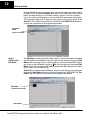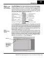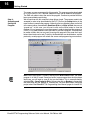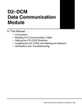
1
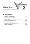
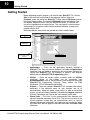
10
Getting Started
Getting Started
Before beginning to edit a program, you need to open DirectSOFT32. Click on
Start in the lower left–hand corner of the computer monitor. Now go to
Programs, place the pointer on DirectSOFT4 then click on DSLaunch (rocket)
in the drop–down window. The following DSLaunch window will appear. From
this window, additional utilities, such as, the DSData Server, CTRIO WB, etc.,
can all be launched from one central place. This same place is used to create
and manage PLC programs and the communications between your personal
compter and the PLC.
Notice the different areas which are pointed out in the Launch window.
Windows–type Menu
Tree
Utilities, such as the
DSData Server
Documents – Projects
most recently used are
listed first
Installed Support
Communication Links
to PLCs
D
D
D
D
Applications — These are the applications currently installed in
DirectSOFT32. They are visible in the Menu Tree under the Applications
folder/icon and are linked to applications that have been designed for
launch from DirectSOFT32. For example, to create a new program
double-click the DirectSOFT32 Programming name.
Utilities — There are several utilities available under the Utilities
folder/icon. Some of the utilities can be purchased from
AutomationDirect, such as, DSData Server. Other utilities will come with
DirectSOFT32 Programming Software. These utilities are ERM
Workbench, CTRIO Workbench and NetEdit.
Projects — These are created in DirectSOFT32. A project (also called a
document) is the collective name for your program and all its
documentation. When you create a new project, or work on an existing
project, you will see it listed in the Menu Tree under the Projects folder/icon
by name. Documents are listed in the “most recently used” order.
Comm Links — The “links” are for communication links between your
personal computer and one or more PLCs. The links are not only for the
control programs. Instead they are communication links (i.e., the link
between the computer and printer). Any application can use the link. When
you create links, they will appear in the menu tree under the Comm Links
folder/icon.
DirectSOFT32 Programming Software Quick–start Manual, 5th Edition, 8/02
11
11
Getting Started
Begin Editing a Program
Step 1:
Enter the Program
Mode
Once the DirectSOFT32 Programming Software is installed in you computer, you
will want to begin to use it. The following steps will show you the basic steps for
editing with DirectSOFT32. This will not be an attempt to teach you how to
develop a control program, but it will give you the basics to get started using
DirectSOFT32 so that you can edit a program.
To begin a new program (project) double–click on DirectSOFT Programming 4
located in the Applications folder of the menu tree.
Step 2:
You should now see the New Project window. You can name a project using any
Start a New Project combination of 15 characters (including spaces). “EXAMPLE1” is the project name
used for this example. Move the selection bar to the PLC Family and CPU Type. For
this example, use a PLC belonging to the DL05/06/105/DL205/DL405 families. Click
on OK after you have made your Family and Type selections. If you have a DL305
type PLC, be sure to select it from the choices. Keep in mind the available
mnemonics, processing rules and even the tool bar characteristics are tailored to the
Family and Type selections that you make.
Use this icon to
start a new project
and open up a
fresh program
window.
New Project
Window
Type in a name
for your project
Select the
PLC Family..
Select the
CPU Type..
..then click on
OK
DirectSOFT32 Programming Software Quick–start Manual, 5th Edition, 8/02
12
Getting Started
After clicking OK to enter your project name, you will see ladder logic rungs ready to
be edited. This is the View Only Mode at this point. In this mode, the cursor is always
hollow and programming is not allowed. Viewing a project is all that is allowed.
If you are a “seasoned” programmer, you may not like the appearance of the display.
This would be a good point to select the color options of your choice. Refer to the
DirectSOFT32 Programming Software User Manual, PC–DSOFT32–M, chapter 4,
to setup the appearance of the programming window.
View Only
Mode
(cursor is hollow)
Step 3:
Switch to the
Edit Mode
The Edit Mode is used to write the control program. You have the option of entering
the Edit Mode in three different ways, the most common being to click on the Edit
Mode button on the top tool bar. It will be yellow in color and indicate OFF. Another
way to turn on the Edit Mode is to click on Edit at the top menu bar, then select Edit
Mode. The last way to enter the Edit Mode is to hold down Ctrl + E (press the Control
key and the E key simultaneously).
DirectSoft32 will indicate the Edit Mode to be active when the cursor box becomes
solid and the Edit Mode button turns white and changes from OFF to ON. The Tool
Palette will also appear on the bottom of the programming window.
Edit Mode
(cursor box is solid)
Tool Palette
DirectSOFT32 Programming Software Quick–start Manual, 5th Edition, 8/02
13
13
Getting Started
Step 4:
Using the Ladder
Palette to Enter
the First Element
Step 5:
Enter the Input
Element
The Ladder Palette can be very helpful, especially in the beginning while learning to
program with DirectSOFT32. Later, you may prefer to use the faster Hot Keys
instead of clicking on the tool buttons. The hot keys are shown on each tool button
and appear whenever your cursor is on the tool button. Refer to the DirectSOFT32
Programming Software User Manual for more details. The Ladder Palette shown
below may not be exactly like the one you have on your computer screen. The tools
used in the Ladder Palette will depend on which CPU your PLC is using. This
example shows the elements common to all of the CPUs.
Normally Open Contact
Normally Closed Contact
Normally Open Immediate
Contact
Normally Closed
Immediate Contact
Equal-To Contact
Not-Equal-To Contact
Greater-Than-or-Equal-To
Contact
Less-Than Contact
Browse Contacts
Browse Coils
Browse Boxes
Browse Elements
Wire to Output
Wire Connection to Stage
Use the Ladder Pallete to enter the first instruction of the program. First, move the
cursor to the desired location for the first element. This is done with either the mouse
or the up and down arrows on the keyboard. When using the mouse, simply position
the mouse arrow to the point where you want the element to be placed and click the
left mouse button. In this example, a normally open contact will be placed at the first
position on Rung 1. Position the cursor at the beginning of the rung and click on the
Normally Open Contact symbol on the Tool Pallete.
You will see the cursor change to a box with an open relay contact, a window with the
text cursor blinking at the end of address C0 (highlighted) and a green indicator. If the
green dot changes to red, it means that the address is incorrect, not valid or a wrong
character. For example, if you typed the letter O instead of the digit 0, the indicator
would turn red and stay red until you correct your mistake. Enter X0 while C0 is
highlighted. After the address has been entered and the error indicator is green,
either click on the check mark (3) or press the Enter key.
Enter X0
Notice the Error
Indicator will be
green when a
valid contact is
entered
DirectSOFT32 Programming Software Quick–start Manual, 5th Edition, 8/02
14
Getting Started
The instruction has been entered and the cursor has moved to the next entry
position. Notice the yellow vertical bar that appears next to the rung. Since this is not
a color manual, a light colored vertical bar is seen in the screen example. The yellow
bar indicates that an instruction or instructions have been entered, but that the
program has not been accepted (compiled).
Rungs that have already been accepted into compiled memory will have a green bar
instead. Without being compiled, you will not see the icons for Save to Disk or Save
to PLC enabled. This means in order to save your program anywhere you will have
to Accept your editing first. For example, if you wanted to stop working with
DirectSOFT right now, you would first want to accept all the edited rungs so that you
could save the revised program to disk.
Yellow color coded
bar indicates the
rung has not been
accepted yet
Step 6:
Enter Ouput
Elements
Next, move the cursor to the end of the rung, over the NOP. Click on the Browse
Coils button on the tool palette. The Instruction Browser will appear with the
Standard Coil selected as the default. Click OK to enter a standard coil.
DirectSOFT32 Programming Software Quick–start Manual, 5th Edition, 8/02
15
15
Getting Started
Step 7:
Element Entry
Window
The Instruction Browser will be replaced with the element entry box. The default
address, C0, will be highlighted. Key in Y0 > Enter. When the address is entered
correctly, the error indicator will be green.
Enter Y0 here
Rung 1 has just been programmed. This rung can be downloaded to the PLC
element except for one missing element. The program must be terminated with
an END Coil rung.
Step 8:
To program this rung, move the cursor so it is over the NOP in the next rung, and click
Enter the END Coil on the Browse Coils button. The Instruction browser will appear. Either move the
up/down arrows or use the mouse to select Program Control in the Coil Class
section of the window. END will be at the top of the Coils list and it will be highlighted.
Click on OK to enter the element.
DirectSOFT32 Programming Software Quick–start Manual, 5th Edition, 8/02
16
Getting Started
Step 9:
Accepting and
Saving the
Program
Two rungs are now programmed for this example. This program can be downloaded
to a PLC the way it is or , if desired, additional rungs can be added to the program .
The END coil needs to be at the end of the program. Continue to practice what has
been covered before continuing.
We will continue with this example to keep things simple. The program needs to be
accepted in order to be downloaded to the PLC. Click on the Accept button in the
menu toolbar to compile the program. Notice that the two diskette buttons on the left
of the menu toolbar are enabled to Read from Disk or to Write to Disk, they are not
“grayed out”. In this case, you will want to click on the Write button to save the
program (it is not necessary to save the program in order to download the program to
a PLC). It is a good practice to save your work as you edit a program. A mistake may
be made at times and you may want to restore the program to the state that it was
before the mistake was made. To do this, the Read button can be clicked on, and the
previously saved program will refresh the screen and programming can continue.
Note: When the program is saved by clicking on the Write to Disk button, the ladder
program is all that is saved. Once you have a larger program than what has been
done here, you will want to save all that you have done. This is accomplished by
selecting File > Save Project to Disk. You can also click on Backup to accomplish
the same thing with the addition of a Backup file. For more detail about saving the
project refer to the DirectSOFT32 Programming User Manual, pages 3–6 and 6–25.
DirectSOFT32 Programming Software Quick–start Manual, 5th Edition, 8/02