1
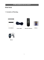
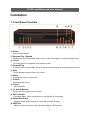
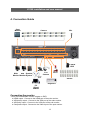
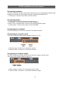
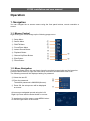
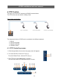
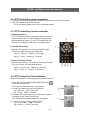
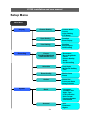
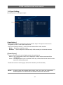
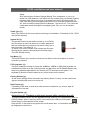
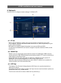
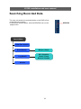
H1169 – Installation and User manual H1169 Real time D1/16ch DVR with HD Display H1169 installation and user manual This page is intentionally left blank 2 H1169 installation and user manual CE Information The product must be installed according to the currently valid installation regulations for EMC to guarantee the designed use and to prevent EMC problems. The device supplied with this manual is according to the EC, EMC Directive, 89/336/EEC & LVD 73/23/EEC Standard used for showing compliance with the essential requirements of the device: EN 55022 EN 61000-3-2 EN 61000-3-3 EN 50130-4 EN 55024 LVD: EN60950-1 Safety Precautions Caution Before Use Please read this manual before installing or using the Vista Quantum DVR. Please keep this manual in a safe place, to allow for future reference For the safety and proper use, The DVR is marked with various symbols. Please read these to prevent injury of financial loss. Installation Site Ensure installation position is level, secure and adequately ventilated. Avoid installing close to sources of humidity or water. 3 H1169 installation and user manual This page is intentionally left blank 4 H1169 installation and user manual Contents OVERVIEW .......................................................................................................................................... 7 1. CONTENTS OF PACKING ................................................................................................................. 7 2. FEATURES ....................................................................................................................................... 8 INSTALLATION ................................................................................................................................... 9 1. FRONT PANEL CONTROLS .............................................................................................................. 9 2. REAR PANEL CONNECTORS ......................................................................................................... 10 3. REMOTE CONTROL ....................................................................................................................... 12 4. CONNECTION GUIDE ..................................................................................................................... 13 5. TURNING ON THE DVR ................................................................................................................. 15 OPERATION ....................................................................................................................................... 16 1. NAVIGATION ................................................................................................................................... 16 1-1. Mouse Control ........................................................................................................................................ 16 1-2. Menu Navigation .................................................................................................................................... 16 2. MONITORING ................................................................................................................................. 17 2-1. OSD Description ..................................................................................................................................... 17 2-2. Select Channel ....................................................................................................................................... 17 2-3. Digital Zoom ........................................................................................................................................... 18 3. PLAYBACK...................................................................................................................................... 19 3-1. OSD Description ..................................................................................................................................... 19 3-2. Playback Control .................................................................................................................................... 19 3-3. Playback Search .................................................................................................................................... 20 4. PTZ CONTROL .............................................................................................................................. 21 4-1. PTZ Control by mouse............................................................................................................................ 21 4-2. PTZ Control by remote keyboard ........................................................................................................... 23 4-3. PTZ Control by remote controller ........................................................................................................... 23 4-4. PTZ Control by Client software ............................................................................................................... 23 SETUP MENU ..................................................................................................................................... 24 1. DISPLAY ......................................................................................................................................... 26 1-1. Camera Setting ...................................................................................................................................... 26 1-2. Spot Setting ............................................................................................................................................ 27 1-3. Live Setting............................................................................................................................................. 28 2. RECORDING................................................................................................................................... 29 2-1. Frame ..................................................................................................................................................... 29 2-2. Schedule ................................................................................................................................................ 30 2-3. Event Configuration ................................................................................................................................ 31 2-4. Action ..................................................................................................................................................... 32 3. SYSTEM ......................................................................................................................................... 33 3-1. Basic....................................................................................................................................................... 33 3-2. Account................................................................................................................................................... 36 4. NETWORK ...................................................................................................................................... 37 4-1. IP Set ...................................................................................................................................................... 37 4-2. DDNS Set ............................................................................................................................................... 37 4-3. NTP Set .................................................................................................................................................. 37 5. EVENT............................................................................................................................................ 38 5-1. Beeper/E-mail Setup .............................................................................................................................. 38 5-2. E-Mail Registration ................................................................................................................................. 38 5-3. SMTP Mode............................................................................................................................................ 38 SEARCHING RECORDED DATA ................................................................................................... 39 1. DATE/TIME SEARCH ...................................................................................................................... 40 2. EVENT SEARCH ............................................................................................................................. 42 5 H1169 installation and user manual 3. LOG SEARCH ................................................................................................................................. 43 4. ARCHIVING EVIDENCE TO DVD/CD OR USB .............................................................................. 44 CLIENT VIEWER SOFTWARE ....................................................................................................... 46 1. LIVE MONITORING ......................................................................................................................... 49 2. REMOTE SEARCH.......................................................................................................................... 52 2-1. Search .................................................................................................................................................... 52 2-2. Archive.................................................................................................................................................... 54 2-3. Remote Log ............................................................................................................................................ 57 3. REMOTE SETUP (MENU SETTINGS - SAME AS DVR)................................................................... 58 3-1. Display.................................................................................................................................................... 58 3-2. Recording ............................................................................................................................................... 59 3-3. System ................................................................................................................................................... 60 3-4. Network .................................................................................................................................................. 60 3-5. Event ...................................................................................................................................................... 61 4. LOCAL SEARCH (VIEWING DOWNLOADED FOOTAGE) .................................................................. 62 4-1. Search .................................................................................................................................................... 62 4-2. Log ......................................................................................................................................................... 64 4-3. Info ......................................................................................................................................................... 64 5. LOCAL SETUP ................................................................................................................................ 65 5-1. Global ..................................................................................................................................................... 65 5-2. Opacity ................................................................................................................................................... 65 5-3. Audio Buffer ............................................................................................................................................ 66 6. TELEMETRY CONTROL (PAN/TILT/ZOOM/FOCUS) ....................................................................... 67 6-1. Pan / Tilt / Zoom / Focus ........................................................................................................................ 67 6-2. Preset / Learn ......................................................................................................................................... 68 7. FIRMWARE UPGRADE ................................................................................................................... 69 APPENDIX 1 ....................................................................................................................................... 70 DYNAMIC IP (SUPPORTING DDNS SERVER)................................................................................... 70 APPENDIX 2 ....................................................................................................................................... 72 SETUP FOR DVR PORT & WEB SERVER PORT USING IP SHARING ROUTER ................................ 72 APPENDIX 3 ....................................................................................................................................... 73 SPECIFICATION .................................................................................................................................. 73 6 H1169 installation and user manual Overview 1. Contents of Packing User Manual Power Cable Remote Controller Mouse 7 Battery H1169 installation and user manual 2. Features ● Convenience - User-friendly GUI (Graphical User Interface) - Easy-to-use menu structure - Easy-to-use recorded data search (Time, Date, Motion, and Alarm) - Easy-to control via Front Panel, IR remote control and USB 2.0 mouse. ● Stability - Auto restart after power interruption - DB structure offers data stabilisation and better storage utilisation ● Expandability - Remote DVR‟s can be controlled using the supplied software client viewer. ● Technology - Embedded LINUX OS - Maximum record rate 400fps(PAL)/ 480fps(NTSC) - High-resolution & high-quality H.264 algorithm - Uses watermarking & scrambling technologies, - H.264 : 1 ~ 2 Kbytes per image with resolution 360x240 ● Functionality - Variable recording function (normal, alarm, motion, schedule, duration, Time Lapse,) - RS485 Telemetry - Full channel real-time monitoring - Live monitoring, recording, playback, backup, remote access simultaneously - Multi channel playback - Variable events notification to e-mail, buzzer or PC Client system 8 H1169 installation and user manual Installation 1. Front Panel Controls ⑬ ① ② ③④ ⑤ ⑪⑩⑫ ⑭ ⑥ ⑦⑮ ⑨ ⑧ ① Power System Power On/Off ② Reverse Play / Rewind Reverse play of recorded data. When in play mode press again to enter fast rewind mode. ③ Pause To freeze picture on playback mode and live mode. ④ Forward Play Playback of the recorded data. When in play mode press again to enter fast forward mode. ⑤ Stop To stop playback and go back to live mode. ⑥ Menu Displays the menu on the screen ⑦ Search Entering search mode ⑧ Select Menu selection ⑨-⑫ Arrow Buttons Moves the cursor while in menu mode ⑬ REC Indicator Recording status. When recording is on, the light will be illuminated. ⑭ Network Indicator Network status. When network is connected, the light will flash. ⑮ USB Port USB connector for mouse control & downloading to USB memory. 9 H1169 installation and user manual 2. Rear Panel Connectors ① ⑥ ② ③④ ⑦ ⑧ ⑨ ⑩ ⑤ ⑪ ⑫ ⑬ ⑭⑮ 16 ① Spot Monitor Outputs Spot Video Output (Composite Video) ② Video Inputs 16 camera inputs ③ Video Outputs 16 camera loop outputs ④ Audio Input Audio input through line ⑤ AC Power Input AC 100-240V 50/60Hz ⑥ VGA Output (Main Monitor) VGA video output for main monitor (1920x1080) 10 17 H1169 installation and user manual ⑦ HDMI Output HDMI output port (1080p) ⑧ VGA Output (Dual Monitor) VGA video output for dual monitor (1024x768) ⑨ Audio Output Audio output ⑩ RS232 Serial Communication (for service) ⑪ Network Port Connecting to the Quantum DVR through Internet or LAN ⑫ USB Port USB 2.0 port for mouse ⑬ E-SATA Port Port for e-SATA HDD ⑭ PTZ Camera Controller Serial Communication for Pan / Tilt Camera ⑮ Keyboard Controller Serial Communication for P/T/Z Control Keyboard 16 Alarm Output Alarm(relay) output port 17 Sensor Input 16 Sensor input ports 11 H1169 installation and user manual 3. Remote Control ① POWER : Power on/off ① ② ② P/T/Z : Entering PTZ Setup menu directly ③ ③ REC : Start & Stop Recording ④ Numbers and letters (1 to 9) ④ ⑤ ⑥ ⑦ ⑧ ⑤ INFO : Direct access system infomation ID : Entering remocon ID set mode MUTE : Audio Mute AUDIO : Switches through Audio channels ⑥ MENU: Entering system menu SEARCH: Entering search ARROW : Left, Right, Up and Down SEL : Select/Enter ⑦ VOL +/- : Up, down volume ⑧ CH +/- : Up, down channel ⑨ (◀)◀ : Reverse play ⑨ ⑩ ⑪ ▶(▶) : Play (or fast forward) I I : Pause ■ : Stop playback ⑩ OSD : On Screen Display ON/OFF SEQ : Sequence operation LOG : Direct access Log list ⑪ CAM : Changing PTZ icon P/T : Pan &Tilt Z/F : Zoom/ & Focus DIS : Channel Division 12 H1169 installation and user manual 4. Connection Guide Spot Monitor Camera Mic e-SATA HDD Mouse PTZ Camera Main Sub Speaker Monitor Monitor System Siren Sensor Keyboard PC (Client) 99Main Monitor Connecting the monitor There are four available monitor outputs on DVR. ● HDMI output : Connect to the HDMI port of the main monitor. ● VGA(main) output : Connect to the VGA port of the main monitor. ● VGA(sub) output : Connect to the VGA port of the sub monitor. ● Composite output : Connect to the Video Input of the spot monitor. 13 H1169 installation and user manual Connecting cameras This unit comes with 16 video inputs. Each video input has a corresponding looping output beneath it for passing the video signal to another monitoring/recording device. ● Video input : Connect to the video out of the camera. Connecting audio To record audio on the DVR, connect to the audio source. ● Audio input : Connect to the audio out of the microphone. To listen to live or recorded audio, connect to an amplified speaker system. ● Audio output : Connect to the audio in of the audio AMP. Connecting to a network Use the ethernet port to connect to remote PC via ethernet network. Connecting to a sensor input There are 16 individual alarm inputs marked as Sensor In (1-16). Common GND Sensor Inputs ● Sensor inputs : Connect to (+) terminal of a sensor. ● Common GND : Connect to (–) terminals of sensors. Connecting to a alarm output The DVR can activate external devices such as buzzers or lights using the relay. There are 4 relay outputs marked as Alarm out. Common Alarm GND Outputs ● Alarm outputs : Connect to (+) terminal of buzzer or light. ● Common GND : Connect to (–) terminals of buzzers or lights. 14 H1169 installation and user manual Connecting to a PTZ camera This RS485 connector can be used to control Pan / Tilt / Zoom camera. (+)(-) ● Telemetry (+) : Connect to RS485 Rx(+) of PTZ camera. ● Telemetry (-) : Connect to RS485 Rx(-) of PTZ camera. Connecting to a remote keyboard This RS485 connector is for a control keyboard. (+)(-) ● Keyboard (+) : Connect to RS485 Tx(+) of the keyboard. ● Keyboard (-) : Connect to RS485 Tx(-) of the keyboard. Connecting to a mouse ● USB 2.0 : Connect to the mouse. Connecting to a external HDD To expand the HDD capacity, connect the external storage. ● e-SATA : Connect to the e-Sata HDD storage. 5. Turning on the DVR 1. Connect the power cable. 2. Connect camera cables. 3. Connect a network cable and a monitor cable. 4. Press the POWER button on the front panel and wait until the main screen is displayed on the connected monitor; this process may take a couple of minutes. 15 H1169 installation and user manual Operation 1. Navigation You can navigate the on screen menus using the front panel buttons, remote controller or mouse. 1-1. Mouse Control Right clicking the mouse brings up the following popup menu. ① Setup Menu ② Search Menu ① ③ PAN/Tilt Menu ② ④ Focus/Zoom Menu ③ ⑤ Instant Record Button ④ ⑤ ⑦ ⑧ ⑥ Playback Button ⑦ Channel Up/Down Button ⑧ Eject Button ⑨ Power Button ⑥ ⑨ 1-2. Menu Navigation To enter the Setup menu, the user has to have the required access rights and be logged on. Press the Menu button or right click with mouse on screen and select the menu icon. The following screen will be displayed asking for password. ① Select the user ID. ① ② ② Enter the password. The default password is 00000000(8 zeros). ③ Press OK, the setup menu will be displayed on screen. ③ All menus are navigated around using the Left/ Right/ Up/ Down and the Select button or mouse. To step back out of the menus, press MENU button or click the right button of the mouse. 16 H1169 installation and user manual 2. Monitoring 2-1. OSD Description The Status Bar on screen shows HDD capacity, network connection, current time, etc. ① ④ ⑤ ⑥ ⑦⑧ ②③ ⑨ ① HDD capacity : Used capacity / Total capacity ② Network connection : It is shown that admin or user is connected. ③ Mouse connection ④~⑧ Multiscreen Display Buttons ⑨ Current Date/Time 2-2. Select Channel Use the Multiscreen display buttons on the status bar to select the display mode. Single Channel 4 Channel Live 1ch Live 4ch 16 Channel 17 Channel Live 16ch 9 Channel Live 9ch Live 4ch + Play 1ch 17 H1169 installation and user manual You can view the 16 live videos and 1 playback video simultaneously in the 17 channel display mode. [ Playback Video ] Channel Up/Down Playback Control Buttons Also you can use the DIS button on the remote controller to change the display mode. Display switches in the following order when the DIS button is pressed. Single Channel 4 Channel 9 Channel 16 Channel 17 Channel 2-3. Digital Zoom When the system is in full-screen playback mode, drag your mouse in the screen to select a section and then left click mouse to realize digital zoom. You can right click mouse to exit. 18 H1169 installation and user manual 3. Playback Click the right button on the mouse, the popup menu will be displayed on screen. To begin playback, press the Play button on the popup menu. 3-1. OSD Description The Control Bar on screen shows Playback control buttons, Progress bar, Display mode buttons, Playback time, etc. ⑫ ⑬ ⑩ ⑦ ⑤ ②③ ①④ ⑥ ⑧ ⑭ ⑨ ⑪ ① Play Forward button ⑧ Stop button ② Reverse Play button ⑨ Display mode buttons (1/4/9/16CH) ③ Pause button ⑩ Playback Speed ④ Frame Advance button ⑪ Playback Date & Time ⑤ Frame Rewind button ⑫ Time Bar ⑥ Fast Forward button ⑬ Previous button ⑦ Fast Backward button ⑭ Next button 3-2. Playback Control Play Forward When the Play Forward button(①) is pressed, the unit will play forward at the rate the data was recorded. While in the play mode, the user may change the playback direction, playback speed. To return to play forward operations, press the Play Forward button(①). Reverse Play To begin reverse playback, press the Reverse Play button(②). Pause During playback, press the Pause button(③). This feature pauses all full screen and multiscreen images. When this button is pressed in the pause mode, the unit will play. 19 H1169 installation and user manual Single Frame Advance During the pause mode, press the Frame Advance button(④) to view the frame directly after the frame displayed on screen. Single Frame Rewind During the pause mode, press the Frame Rewind button(⑤) to view the frame directly before the frame displayed on screen. Fast Forward In playback mode, press the Fast Forward button(⑥) to switch between various fast play modes such as x2, x4, x8, x16 play. Fast Backward In reverse playback mode, press the Fast Backward button(⑦) to switch between various reverse play modes such as x2, x4, x8, x16 reverse play. Stop To stop playback and return to the live mode, press the Stop button(⑧). 3-3. Playback Search The user can search the recorded video during playback. The recorded video is indicated by a colour bar on the time bar(⑫). You can use the Previous(⑬) or Next(⑭) button to view if there are more recorded data. Click the mouse at the desired point of the colour bar, you can view the recorded data. 20 H1169 installation and user manual 4. PTZ Control The user can control PTZ cameras via RS485 communication. The PTZ domes can be wired in a Daisy chain. Daisy Chain configuration The telemetry function of DVR can be controlled via 4 different methods: 1. Mouse 2. Remote keyboard 3. Remote controller 4. Software viewer 4-1. PTZ Control by mouse 1. Click the right button the mouse, the popup menu will appear. 2. To control Pan/Tilt, click the P/T icon(①). ① ② To control Zoom/Focus, click the Z/F icon(②). 3. The PTZ menu will be displayed on screen. The user can control PTZ cameras using PTZ menu. ①② ③ ④ ⑥ ⑤ ⑧ ⑨⑩ ⑦ ⑪ 21 H1169 installation and user manual ① Dome Menu : Entering the Dome Camera menu ② Multiscreen Display : Changing the display mode ③ Set Preset ④ Pan Left / Focus Near ⑤ Pan Right / Focus Far ⑥ Tilt Up / Zoom In ⑦ Tilt Down / Zoom Out ⑧ Call Preset ⑨ PTZ Camera Selection ⑩ Exit ⑪ PTZ Mode : The PTZ mode is toggled between P/T and Z/F mode whenever this button is pressed. [ Camera selection ] The PTZ cameras can be controlled in either full screen or split screen mode. If in split screen mode press the PTZ Camera Selection button(⑨), the PTZ camera icon will step from one camera to the next on the split screen. [ Pan and Tilt control ] Press the PTZ Mode button(⑪) to enter the Pan/Tilt mode. To move the dome use the arrows buttons; Left(④) : Pan left, Right(⑤) : Pan right, Up(⑥) : Tilt up, Down(⑦) : Tilt down [ Zoom and Focus control ] Press the PTZ Mode button(⑪) to enter the Zoom/Focus mode. To zoom or focus use the arrows buttons; Left(④) : Focus near, Right(⑤) : Focus far, Up(⑥) : Zoom in, Down(⑦) : Zoom out [ Preset positions ] 1. To store a preset position, move the camera to the required position. 2. Press the Set Preset button(③), the popup window will appear. 3. Enter the preset number to be stored then press OK. [ Call Preset ] 1. To recall a preset position press the Call Preset button(⑧), the popup window will appear. 2. Enter the preset number you want then press OK. 22 H1169 installation and user manual 4-2. PTZ Control by remote keyboard 1. Select Dome from the keyboard, ensure the keyboard is in Pan and Tilt mode. 2. Use the joystick to move the camera. * For more detail, please refer to your keyboard manual. 4-3. PTZ Control by remote controller [ Camera selection ] The PTZ cameras can be controlled in either full screen or split screen mode. If in split screen mode press the camera selection button(①), the PTZ camera icon will step from one camera to the next on the split screen. ⑦ ⑥ ⑤ [ Pan and Tilt control ] Press the P/T button(②) to enter the Pan/Tilt mode. To move the dome use the arrows buttons; Left(⑤) : Pan left, Right(⑥) : Pan right ⑧ Up(⑦) : Tilt up, Down(⑧) : Tilt down [ Zoom and Focus control ] Press the Z/F button(③) to enter the Zoom/Focus mode. To zoom or focus use the arrows buttons; Left(⑤) : Focus near, ①②③ ④ Right(⑥) : Focus far Up(⑦) : Zoom in, Down(⑧) : Zoom out 4-4. PTZ Control by Client software While Client software is running select the dome required. 1. Enter the Pan/Tilt mode by pressing the PTZ icon at the top of the screen. The Pan/Tilt control window(①) will appear. 2. To move the dome use the arrows buttons; Left : Pan left, Right : Pan right Up : Tilt up, Down : Tilt down ① ⑤ 3. Press the Z/F mode button(②) on the control window to change to the Zoom/Focus mode. The Zoom/Focus control window(③) will appear. 4. To zoom or focus use the arrows buttons; Left : Focus near, Right : Focus far Up : Zoom in, Down : Zoom out 23 ③ ② H1169 installation and user manual Setup Menu Main Menu Display Recording Camera Setting Spot Setting Duration Event Popup Live Setting Duration Event Popup OSD Setting Frame (Day/Night/Weekend /Time/Instant Rec) Resolution Recording Mode Frame Picture Quality Audio Pre Recording Schedule Day/ Night Weekend/ Holiday Time Event Config System Camera Name Covert Color Setting PTZ Setup Motion Area Alarm Action Alarm Out Preset on Alarm Relay Follower Basic Language Time/DST Set Video Type PTZ Controller Disk Format Program Update Information Account 24 User Password Rights H1169 installation and user manual System Language Time/DST Set Video Type PTZ Controller Disk Format Program Update Information Basic Account Network IP Set DDNS Set NTP Set Event Beep E-mail Registration SMTP Set 25 User Password Rights H1169 installation and user manual 1. Display 1-1. Camera Setting Use this menu to adjust the picture colour and specify cameras as covert (recorded but not displayed). Click the camera icon(①) on the left hand to select the desired camera. ① [ Camera Name ] Each camera can be titled using the mouse and each title can have up to 30 characters. Use the mouse to select the title to alter, the on screen keyboard will appear, enter the title followed by the OK button. [ Camera Covert ] Camera can be hidden from the viewer in live or play back mode. Click the check box to hide the camera. In order to view covert camera in Live or Playback, it needs to be turned off in the menus, this is requires the necessary user rights. [ Color Setting ] The picture displayed from each camera can be individually adjusted to balance the multi screen view. Move the control bar to change the values of Hue/ Saturation/ Contrast/ Brightness. [ PTZ Setup ] You can control PTZ cameras via coax or a RS485 connection on the rear of this DVR. The cameras can have individually selectable protocols with a choice of Pelco-P or Pelco-D etc. ID : Set the PTZ ID from 1-255. Protocol : Select a PTZ protocol. Baud rate : Select a baud rate. 26 H1169 installation and user manual 1-2. Spot Setting Use this menu to set the spot output. ① [ Spot Setting ] Spot output is used to configure the second monitor output. The spot monitor can be configured for full or multi-screen sequences. Click one of the spot icons(①) on the left hand and set the mode, duration. Mode : Select the sequence mode. Duration : Set the sequence interval time(0~240 seconds) for individual cameras. [ Event Popup ] The spot monitor can be set to display events, the options are: Motion : Any camera with motion will be displayed, multiple motion cameras will be sequenced. Alarm : If the single alarm input is activated, then any camera that has the alarm function turned on will be sequenced. Enable the motion or alarm popup and set the duration (0~240 seconds). NOTE : In order to save any modified setting value, click “YES” when the confirmation window appears. This action can be carried out within each sub menu. 27 H1169 installation and user manual 1-3. Live Setting Use this menu to set up a sequence of the screen. [ Live Setting ] The live settings are used to set up a sequence of either full screen camera images or multi screen displays. The display will change to allow individual sequence times to be set per channel or split screen option. Mode : Select the sequence mode (full screen, quad or nine way split sequences). Duration : Set the sequence interval time(0~240 seconds) for individual cameras. [ Event Popup ] The Main screen can be set to display events, the options are: Motion : Any camera with motion will be displayed, multiple motion cameras will be sequenced. Alarm : If the single alarm input is activated, then any camera that has the alarm function turned on will be sequenced. Enable the motion or alarm popup and set the duration (0~240 seconds). [ OSD Setting ] Selecting how long the graphic information is displayed on the screen. Status Bar The display bar at the bottom of the screen can be set to be permanently on or to disappear after a period of time. Event Display Icons such as recording mode, motion detection can be displays or not. Camera Name The camera title can be displayed or not. Blending The opacity of the menus and Status bar can be set between 0 and 5, 0 is solid, 5 being very opaque. 28 H1169 installation and user manual 2. Recording 2-1. Frame This configures the FPS for each schedule – Day/ Night/ Weekend & Holiday/ Time/ Instant recording. ⑥ ⑦ ⑧ ⑨ ⑩ ⑪ ⑫ ⑬ ① ② ③ ④ ⑤ In Frame Setup, user can define the recording schedule : ① Day ② Night ③ Weekend/Holiday ④ Time ⑤ Instant Recording Click the recording schedule (①~⑤) you want to set and set the follow items. Resolution (⑥) Each channel can be individually configured for record rate (CIF/2CIF/D1). Recording mode (⑦) : [C] / [A] / [M] / [A+C] / [M+C] / [A+M] / [A+M+C] C : Continuous , A : Alarm , M : Motion Continuous Recording FPS (⑧) : Alarm Recording FPS (⑨) : NTSC : 0~30fps , PAL : 0~25fps NTSC : 0~30fps , PAL : 0~25fps Motion Recording FPS (⑩) : NTSC : 0~30fps , PAL : 0~25fps Quality (⑪) : Low / Middle / High Audio recording (⑫) : Enable each audio channel for recording. Post recording time (⑬) : This is the time for which the DVR will record after the motion/ alarm occurs. It can be set to 1~99 seconds. 29 H1169 installation and user manual 2-2. Schedule Use this menu to configure the recording schedule. ③ ① ② Day/ Night (①) Define the day and night. Ex) If 18:00 to 6:00 is defined as night time, 6:00 to 18:00 is defined as daytime. Weekend / Holiday (②) Define weekend. (1) Click a date for holiday on the calendar. (2) Define holiday by the following method; 1) Date of month 2) Day of week ** Click a date again to cancel. Time (③) The time recording allows the DVR to be set to only record at particular times of the day. Set the recording time; 1) Day 2) Start Time 3) End Time 4) Channel 30 H1169 installation and user manual 2-3. Event Configuration Use this menu to configure the motion & alarm settings. ① ② ③ ④ ⑤ ⑥ [ Motion ] Motion On/Off [①] Specify whether to use motion input or not. Motion Sensitivity [②] Low / Middle / High Motion Area [③] Define the motion detection area. 1) Click the “Set” to setup the motion detection grid per channel. The detection area is divided into cells. Default is all cells in active mode. 2) Select cells and toggle them on and off. Click icons (⑥) if you want to select the motion area by the block. ** The motion detection is not recommended for external cameras. [ Alarm ] Sensor On/Off [④] There are 16 alarm(sensor) inputs on the rear of the unit. Click the check box to enable each sensor. Sensor Type [⑤] Select the sensor type; NO(Normally Open) or NC(Normally Closed) 31 H1169 installation and user manual 2-4. Action Use this menu to configure the relay settings relating to the event (motion & alarm). ① ② ③ ④ ⑤ ⑥ ⑦ ⑧ ⑨ ⑩ [ Motion ] Relay On/Off [①] ⑥ Associate the relays with a channel. Click the check box to enable each relay. The associated relays will be on when the motion is detected. Duration [②] This is the time for which the relay will be on. It can be set to 0~999 seconds. [ Alarm ] Relay On/Off [③] Associate the relays with a channel. Click the check box to enable each relay. The associated relays will be on when a sensor alarm happens. Duration [④] This is the time for which the relay will be on. It can be set to 0~999 seconds. Preset on alarm [⑤] You can enable PTZ camera to move to a preset position when a sensor alarm occurs. A single alarm input can be used to drive up to 4 PTZ cameras to preset positions or preset tours. Select the PTZ camera (⑥), PTZ mode(⑦), preset number(⑧), screen view(⑨). [ Relay Follower ⑩] Use this menu if you want to use the matrix switcher. DVRs can be linked to a single matrix switcher and in-turn fed into a monitor. The monitor displays the video from one of DVRs when the matrix switcher detects the relay signal from DVR. 32 H1169 installation and user manual 3. System 3-1. Basic Use this menu to set Language, Time/DST, Video Type, System ID, PTZ controller. Also, Initialisation and System Information is available. ① ② ③ ④ ⑨ ⑩ ⑪ ⑫ ⑬ ⑤ ⑥ ⑦ ⑧ Language (①) The default is English. French, German, Italian, Dutch, Hungarian, Slovak, Spanish, Portuguese, Danish and Polish are available. Auto Delete Mode (②) Auto Delete Mode can be set to automatically erase recorded older than a certain number of days. This can be set between 0 and 99 days. Date Format (③) The default is dd-mm-yyyy. Other date formats available are: mm-dd-yyyy / / yyyy-mm-dd. Time/DST Setting (④) The DVR‟s time can be set by clicking on the time and date displayed in this section, the on screen keyboard will appear. Set the time and date and click OK, next select the country to enable the Day Light Saving mode. ** NOTE : Playback following time change The DVR uses the time and date to index video on the hard disk drive so you can find it later. Changing the time can cause the DVR to work improperly, when you try to play back video. If you set the hour ahead, this is not a problem. But, if you set the hour back, there will be more than one recording with the same time 33 H1169 installation and user manual stamp. Such as during the October Daylight Saving Time changeover, if you try to search for video between 1 am and 2 am, the recorder may not operate properly because there will be two hours of recorded video during this time period. To view video during this overlapping time period, you must start playback before 1 am, then recorder will play both hours between 1 am and 2 a.m. You cannot do a backward search through the overlapping time. But, you can do forward search. Video Type (⑤) Video Type can set in this menu without rebooting or initialisation. The default is PAL, NTSC can also be selected. System ID (⑥) The remote control can be used to control up to 16 DVRs, the ID number on each can be set to a unique address so that the remote will only control one at a time if they are in close proximity. The default is 11. To select a unit on the remote control press the ID button, followed by the number, followed by the ID button again. The LED will flash slowly. LED Key Beep (⑦) The buzzer can be set to sound on whenever the button on the front panel or remote controller is pressed. PTZ Controller (⑧) This DVR needs to be setup to accept the VKBD3im, VKBD4 or QSC1000 keyboard, as a default this will be set to the correct protocol and baud rate, the ID RS485 address may need to be adjusted dependant on the number of PTZ cameras on the system. The keyboard ID should not be the same as any of the domes on the system. Factory Default (⑨) All the menu settings will be returned to the factory default. To carry out this function the system recording will have to be turned off. Disk Format (⑩) Formatting of the drive is used when new drives are installed or you need to wipe all information on the disk. Program Update (⑪) Always turn off : Playback and Network access while upgrading the unit The latest firmware version can be upgraded through USB 2.0 Port using Memory Stick or CD/DVD Media. When a memory stick is connected to the USB port, this symbol will be shown in the status bar of the screen. Click the SEL. If the system recognizes the new firmware then, “Confirmation window” will be displayed on the screen. 34 H1169 installation and user manual Next click the “SEL” on the confirmation window. Processing percentage will be displayed. The message window will be displayed on the screen after upgrading the program. Click “POWER” on the message window, the DVR will be rebooted. Smart (⑫) This function is used to keep a check on the health of the Hard disk. The parameters which can be monitored are: 1. Read/Write errors on the drive 2. Drive temperature. Smart : Turn to on to enable feature. Temperature : Using the on screen keyboard set the temperature at which the warning is to be reported. (recommended setting 45℃) Message Box : The message box can be turned on or off to give a visible warning. Information (⑬) The Information Screen shows the hard disk size, current firmware version, IP address and MAC address. 35 H1169 installation and user manual 3-2. Account The DVR can have the following different levels of operators, each with different user rights and passwords: ① ② [ Adding the operators on the list ] Click the Add(①), new user name will be displayed on the list. Level Admin level : Operators logged in at this level has full rights Manager level : Operators logged in that this level as default have access to all except: Stopping recording and shutting down the DVR. Users 1-11 : Operators logged in at this level only have the ability to search and play, control PTZ cameras and get access via the network. ID Enter the operator ID using the on screen keyboard. Password Enter the operator password using the on screen keyboard. Rights Click the check boxes beside Rights. Each users rights, can be individually tailored to their own requirements, the amending of these rights can only be done by an administrator level log on. [ Amending operators settings and user rights ] Click the operator you want to amend on the list. The operator ID & password can be changed using the on screen keyboard. Also the operators user rights can be amended. If you want to delete the user name from the list, click the Del(②). 36 H1169 installation and user manual 4. Network Use this menu to configure network settings; IP, DDNS, NTP. ③ ① ② ④ 4-1. IP Set When a fixed IP address is being used, the Use Dynamic IP should be set to OFF. The IP Address, Gateway and Subnet Mask need to be set, these will generally be given by the network manager. DSL refers to all types of Digital Subscriber Line such as ADSL and SDSL. The DVR Port and WEB Port can both be changed if required, default are 2000, and 80 respectively. 4-2. DDNS Set DDNS is a service that maps Internet domain names to IP addresses. DDNS serves a similar purpose to DNS: DDNS allows anyone hosting a Web or FTP server to advertise a public name to prospective users. Unlike DNS that only works with static IP addresses, DDNS works with dynamic IP addresses, such as those assigned by an ISP or other DHCP server. What this means is that the DVR does not need a Static IP address to be available for viewing remotely over the World Wide Web. 4-3. NTP Set The Network Time Protocol Setting allows the DVR time to be synchronised with an external time server. The default is NTP OFF. When turned on the Type of service can be selected, options are Default (time.bora.net), Domain and IP. The time zone can also be chosen within the City selection(④). 37 H1169 installation and user manual 5. Event This menu is used to inform the user as to an event occurring, this can be by the sounding of a buzzer or by sending an E-mail to a predefined address. ① ② ③ 5-1. Beeper/E-mail Setup Beep Out The buzzer can be set to sound on the following occurrences: Video Loss, Alarm input, Motion detection, Power Loss. The duration of the beep can be set (1~999 seconds or continuous). E-mail Out As well as e-mail on event activations the DVR can be set to send a report on the following occurrences: Video Loss, Alarm, Motion, Power Loss. 5-2. E-Mail Registration Within this section up to 3 users can be set-up to receive an email on the occurrence of an event such as Video Loss / Alarm / Motion or Power Loss. An E-mail will only be sent if the DVR is sitting on a network with access to the Internet, e.g. through a router. The user name & e-mail address are set from the on screen keyboard via the mouse. The Sender Address is the address that will appear on the E-mail received by the user, this should be set logically to identify the specific DVR. The report period is used to set how often e-mails are sent: Immediately, Daily or Weekly. “Send Test Mail” sends a test E-mail to the addresses so allowing the installer to verify if the setup is correct. 5-3. SMTP Mode The SMTP(Simple Mail Transfer Protocol) function allows e-mails to be sent over a LAN. The default is SMTP Mode “OFF”. In order to activate SMTP Mode, choose SMTP Mode either IP or Domain first. Then, put ID, Password, Domain/IP, and port. Finally press “SMTP Status Check” to test. 38 H1169 installation and user manual Searching Recorded Data The user can search the recorded video on the DVR to find a specific time or event. To access the search option, click the SEARCH icon on the popup menu. Search Menu Date/Time Search Event Search Log Search Motion / Alarm All / Operation Power / Event Record / Archive Archive 39 SEARCH H1169 installation and user manual 1. Date/Time Search If you select Date/Time Search(①), the following will be shown. ⑩ ⑪ ⑫ ① ② ③ ④ ⑤⑥ ⑦⑧⑨ [ Time Search ] Use this menu to search the recorded data by a specific date and time. 1. Click the start time box(②) to enter the start time, the keyboard will be displayed on screen. Enter the start date & time using the keyboard. 2. Click the end time box(③) to enter the end time, the keyboard will be displayed on screen. Enter the end date & time using the keyboard. 3. Click Play(④) to play back, the selected search result will be played. [ Calendar Search ] The Calendar search gives a graphical representation of when video is recorded on the hard drive. The year and month can be selected. This month is shown as a calendar on the screen, any day which contains recorded video will be indicated by a blue box. 1. Select the year and month by pressing ◀ or ▶(⑤). 2. Select the desired day by pressing the blue box(⑥). 40 H1169 installation and user manual The hours which have recorded data are displayed as a coloured bar on the right-hand side of the screen. - The blue bar(⑦) means the data was recorded by the schedule recording. - The red bar(⑧) means the data was recorded by the alarm. - The yellow bar(⑨) means the data was recorded by the motion. 3. Press the hour(⑩) which you want to review. The minutes which have recorded data will be displayed. 4. Press the minute which you want to review, the selected search result will be played. [ Multiscreen Display & Play Control ] Multiscreen Display Press the Multiscreen icons(⑪) to activate the multiscreen display (1-Channel, 4-Channel, 9-Channel, 16-Channel, Full screen display). Play Control Press the Play mode icons(⑫) to control the play mode (Pause, Reverse play, Forward play, Stop). 41 H1169 installation and user manual 2. Event Search If you select Event Search(①), the following will be shown. ⑦ ① ② ③ ④ ⑤ ⑥ This allows the user to define a search based on event recorded data. Motion : The search is for any motion events within the times defined. Alarm : The search is for any alarm activation within the times defined. 1. Check the box(②) to select between Motion and Alarm. 2. Click the start time box(③) to enter the start time, the keyboard will be displayed on screen. Enter the start date & time using the keyboard. 3. Click the end time box(④) to enter the end time, the keyboard will be displayed on screen. Enter the end date & time using the keyboard. 4. Select cameras(⑤) which you want to review, the selected camera will be indicated by a highlighted icon in white. 5. Press Search(⑥), all event recorded data will be displayed on screen. 6. Click the one(⑦) of event recorded data, the selected data will be played. 42 H1169 installation and user manual 3. Log Search If you select Log(①), the following will be shown. ④ ① ② ③ ⑤ The log file contains information on the following: Power : Power on, Power off, Power fail Record : Rec fail, Rec start, Rec stop, Rec error, Rec full Operation : Play start, Play stop, HDD format, Menu set Event : Alarm, Motion, Audio, Video loss, Email fail Archive : This lists the user, time/date when archive was done, and time range of archived section. A total of 5000 events can be recorded the oldest being overwritten when a new one occurs, they can be viewed all together or as individual types. 1. Check the log box(②) which you want to view. 2. Press Search(③), the selected log list will be displayed on screen. 3. Click the one(④) of log list to view in detail, the detail information(⑤) will be displayed. 43 H1169 installation and user manual 4. Archiving Evidence to DVD/CD or USB Once the required video has been found, it may be necessary to down load it for evidential purposes. This can be done either onto the internal CD/DVD-R writer or via the USB port. To do this press the Archive icon(①). ② ③ ④ ⑤ ⑥ ⑦ ① ⑧ ⑩ ⑨ Device (②) This allows selection between the internal CD /DVD-R writer and the FLASH option via the USB port. Insert a media (disc or USB flash drive) and then press Device box. The media will be recognized by DVR. Device Format (③) Format for CD/DVD-R is not needed. When using a USB pen, the format should be done first. Type (④) Exclusive : If evidence is downloaded as an Exclusive file, the DVR will download bespoke player software on to the CD / DVD or USB device along with the evidence. This means that no special software is required, by the reviewing PC. This format is secure and watermarked. AVI : The evidence is downloaded as an AVI file, this backup file can be played on a PC using the well known media player like Windows media player. Log (⑤) The Log file can be downloaded from this menu screen, check the Log box. 44 H1169 installation and user manual Config (⑥) The Configuration files for the DVR can be downloaded and saved. From / To (⑦) You can set up the start and stop time which is required to be backed up to the internal CD/DVD-R or USB device. Enter the start & end time using the keyboard on screen. Channel (⑧) The number of channels to be down loaded can be selected. Anything from a single channel to all 16 can be selected, the selected camera will be indicated by a highlighted icon in white. Calculate Archive Size (⑨) Once the time and date and file format have been entered, it is necessary to confirm that the size of file created will not exceed the size of memory available on the disk or USB device. The DVR will calculate storage space required for download file. This will be displayed in the Required Size section. As long as the Required Size is smaller than the Free/ total space, then move to Transfer and press it. Transfer (⑩) Press Transfer after finishing the settings, the downloading will start. Percentage done during downloading will be shown. NOTE Do not shutdown the DVR during the archiving process. 45 H1169 installation and user manual Client Viewer software Each DVR comes with license free viewer software to view the DVR across a network. To be able to do this the recommended minimum specification for the PC is as follows: Minimum PC specification > CPU: Core 2 Duo 3.16GHz, > Graphic Memory: 512MB Installing software When you put Quantum Network installation CD into your PC, it will auto run and lead you through an installation wizard. Follow the instructions. Once the software is loaded it will automatically run. Connection To connect to the Unit, open the Viewer Software and click the connection button, 46 H1169 installation and user manual Logging on The following window will appear. To connect to the E4000, enter the units: IP address; DVR Port (2000 ids default), ID and Password. Then, click “OK”, to start the live monitoring. Description field is the name of area / Building / location of the DVR, this should be typed in he first time the unit is connected to, this will store it in the address book. Address book Click on the Arrow to the left of the IP address, the following box will appear. This lists the last 22 units that have been accessed. To reconnect to one of these units simply double click, then add the ID and Password. 47 H1169 installation and user manual Explanation of Screen Buttons 48 H1169 installation and user manual 1. Live Monitoring The software is best viewed with the PC monitor resolution, set to: 1024 x 768. Split Screen options (1/4/6/7/8/9/10/13/6) Spilt Screens can be viewed during both live and playback. The splits screens available are: full screen,4,6,7, 8,9,10,13 and 16 way. 1) Full Screen 2) 10 Way 49 H1169 installation and user manual Full Screen on/ off When the full screen button is selected, a tool bar offering the various split screen options, and the Exit key will be displayed at the bottom of the screen. OSD on/off The OSD button will toggle between the on screen titles etc being shown or hidden (Smart) Arrange On/Off If Cameras are being displayed in segments that are not logical, the Smart button will rearrange and put camera input 1 into segment 1 (Top Left) etc. 50 H1169 installation and user manual Image Save / Load / SAVE: This icon is used to save a still image in either JPEG or BMP or TIF format. There is no change on the main screen when the “Save” icon is pressed. The still image is stored as default in C: H264CD: Saved folder, as a Jpeg image using the date and time as the file name. LOAD: This icon is used to retrieve and view a saved still image, when selected a list of available images will be shown. Select to one required, it will be displayed along with data information (Status-Live/Playback, IP address, CH No.). Playback (Step Backward, Backward, Playback, Pause, Recording, Stop, Step Forward) Audio (Mute, Volume, Select Audio, Microphone) Select Audio: Toggles through audio channels. Microphone: It is used for transmitting audio to the System through a microphone. 51 H1169 installation and user manual 2. Remote Search Search(Date/Time/Event/Calendar), Archive(Remote Archive), Log(Remote Log) are available. 2-1. Search This Remote Search is able to play back video on the PC direct from the hard disk storage on the Quantum Plus. There are 3 options for as follows. 1) Date/Time 2) Event 3) Calendar Date/Time When the cursor is placed over a part of the time and date a drop down arrow will appear, use this to set the required value. When set. Click “Play” button, this window disappears and Remote Playback will start. To stop playing back press Stop the search screen will appear to allow another search to be carried out, if not required, click cancel followed by live . Event Click on the Event button on the right hand side, the software will search for all event types. This may take a short while. A list of the available events will appear. To play an Event select it and click Play. To stop playing back press Stop the search screen will appear to allow another search to be carried out, if not required, click cancel followed by live . 52 H1169 installation and user manual Calendar Select the date required (as long as the date is highlighted in Blue there is recorded data on from that day). There are 3 options for selecting the required time once the date has been selected. 1) Drag the Red line along the colour bar (I.e. Blue: Normal Recording) till the required time is reached. 2) Click on the required time for playback on the blue bar then the red line will move to this point. 3) Hover over the time box, a drop down arrow will appear allowing the manual selection of Hours, mins and seconds. Next click the “Play” button for Remote Playback. Or, click “Prev” to go back to previous stage. 53 H1169 installation and user manual Select Channel Channels can be included or excluded dependent on query. This is available within Search, Backup and Logs. . 2-2. Archive Remote Archive – Date/Time Enter the Start and End dates and times, by hovering over the selections, a drop down box will appear. Once selection is made, then “click” calculate, the file size will be displayed. Finally click “Archive”, the file will be transferred to C:\ H264CD \Download. Remote Archive – Event Select either: Alarm, Motion or Audio from the top of the screen. A list of events will appear. Click on the event required, it will be come highlighted. Click on Calculate, the file size will be calculated, this may take a few seconds. Finally click Archive; the file will be transferred to C:\ H264CD\Download. 54 H1169 installation and user manual Remote Archive – Calendar Select the date required (Days with recorded video a data present are highlighted in Blue) There are 3 options for selecting the required time once the date has been selected. 1) Drag the Red line along the colour bar (I.e. Blue: Normal Recording) till the required time is reached. 2) Click on the required time for playback on the blue bar then the red line will move to this point. 3) Hover over the time box, a drop down arrow will appear allowing the manual selection of Hours, minutes and seconds. Then click the “Next” button to set “End” Archive time, in the same manner. 55 H1169 installation and user manual The backup procedure is same as Date/Time & Event backup as previous page. * “Prev” to go back to previous stage. *The downloaded data is saved in the follows location. C:\H264CD\Download. Play back down loaded files Open the viewer software but do not connect to a unit, click the cancel button to remove the log on box. Next click on the Local search button the normal search box will appear, use the same method to search the files on the PC and Play back 56 H1169 installation and user manual 2-3. Remote Log The Log file can either be viewed or printed. The recorded Event can be played, by selecting it and clicking on Play. The log list can be viewed as a whole or filtered by the following types: Power: Record: Operation: Client: Event: Archive Power on, Power off, Rec fail, Rec start, Rec stop, Rec error, Rec full Play start, Play stop, HDD format, Menu set R_Login, R_Logout, R_Logfail, R_Play, R_Transfer, R_Rec on, R_Rec off, R_Upgrade Alarm, Motion, Audio, Video loss, Email fail. This is a Password protected section, only available to users with the correct rights. Click on the Archive button a password entry box will appear, which has to be completed before the Archive log list will appear. Info “System Info” of the Remote Log The system info displays the Mac address and software version information. “Status Info” of the Remote Log This shows the status of both the Hard disk and the recording modes of each channel. 57 H1169 installation and user manual 3. Remote Setup (Menu settings - same as DVR) 3-1. Display This is the same as the Display Menu of DVR, refer to setting the Display Menu of DVR. [ Camera Setting ] Use this menu to adjust the picture color and specify cameras as covert (recorded but not displayed). [ Spot Setting ] Use this menu to set the spot output [ Live Setting ] Use this menu to set up a sequence of the screen 58 H1169 installation and user manual 3-2. Recording This is the same as the Recording Menu of DVR, refer to setting the Recording Menu of DVR. [ Frame ] This configures the FPS for each schedule – Day/ Night/ Weekend & Holiday/ Time/ Instant recording. [ Event Configuration ] Use this menu to configure the motion & alarm settings. [ Schedule ] Use this menu to configure the recording schedule. [ Action ] Use this menu to configure the relay settings relating to the event (motion & alarm). 59 H1169 installation and user manual 3-3. System This is the same as the System Menu of DVR, refer to setting the System Menu of DVR. [ Basic ] Use this menu to set Language, Time/DST, Video Type, System ID, PTZ controller. Also, Initialisation and System Information is available. [ Account ] The DVR can have the following different levels of operators, each with different user rights and passwords. 3-4. Network This is the same as the Network Menu of DVR, refer to setting the Network Menu of DVR. Use this menu to configure network settings; IP, DDNS, NTP. 60 H1169 installation and user manual 3-5. Event This is the same as the Event Menu of DVR, refer to setting the Event Menu of DVR. This menu is used to inform the user as to an event occurring, this can be by the sound of a buzzer or by sending an E-mail to a predefined address. 61 H1169 installation and user manual 4. Local Search (viewing downloaded footage) This allows playback of video which has been downloaded top the PC. 4-1. Search Searches can be done by Date/Time, Even and Calendar. [ Date/Time ] Hovering over the Date and Time bars will allow drop down boxes to select the required time and Date. Once set, click Play. [ Event ] Choose the Event search box then choose the type of Event you are searching for, options are: Alarms, Motion or Audio. Once the selection is made, a list will appear, choose the Event required and click Play. 62 H1169 installation and user manual [ Calendar ] When the Calendar option is chosen this screen will appear, any day with recording available will be highlighted in Blue. Select the required day. Any downloaded event s will be shown, click on the event, the red line will move to that event. Then click Play to review the recording. 63 H1169 installation and user manual 4-2. Log Clicking on Log will display the log file from the unit. This file can be printed, by clicking Print. 4-3. Info Click on Info. This will display the version of the software client being used. 64 H1169 installation and user manual 5. Local Setup This allows the setup of the viewing of the software on the PC. 5-1. Global This screen allows the following: Draw mode to be set to YUV or RGB Date Format to be set to: DD/MM/YYY, MM/DD/YYYY or YYYY/MM/DD. Save Format, for the saving of stills as either JPEG, Bit Map or TIF. Location for where stills are saved. 5-2. Opacity The opacity or “boldness” of the OSD can be individually set per function. The lower the number the more see through the box. 65 H1169 installation and user manual 5-3. Audio Buffer Audio Buffer settings are there to adjust the audio over the network, this will compensate for different network speeds ( LANs, WANs etc). This can only be adjusted if the LIVE video is switched off. Adjust each variable to achieve best quality video for Network bandwidth available, this is best done through trial and error. 66 H1169 installation and user manual 6. Telemetry Control (Pan/Tilt/Zoom/Focus) When PTZ button is being pressed, PTZ control icon will be pop-up on the live image. 6-1. Pan / Tilt / Zoom / Focus When PAN/TILT button is clicked the Pan/Tilt control appears, this allows Left, Right, Up and Down Control of PTZ cameras When Zoom/Focus button is clicked, the control changes to Zoom in on the up arrow, Zoom out on the down arrow. Focus near on the left button and focus far on the right arrow. 67 H1169 installation and user manual 6-2. Preset / Learn PRESET&LEARN icon The presets button can be activated by clicking on the centre of the control icon, the preset symbol will appear and the Preset selection box will appear. To save a preset, move the camera to the desired position then click “Set” followed by the desired number. To recall the preset, click “Call” followed by the desired number. 68 H1169 installation and user manual 7. Firmware Upgrade User can select Firmware Upgrade menu, if a new version of firmaware exits in the C:/H264CD/Upgrade folder ,then the message „New program found!‟ will be displayed if there is no file then „New program not found!‟ message will be displayed. To proceed with upgrading press the OK button and select each firmware files to upgrade it to the system, by ticking the boxes. Once the upgrade has been completed the following message will appear. Next press the OK button to reboot the DVR, the firmware will only be applied completely once the system is rebooted. Quit (Exiting Client program) To exit the Client viewer program click the Quit button. 69 H1169 installation and user manual Appendix 1 Dynamic IP (Supporting DDNS Server) With DDNS Server, This allows a user to connect to the unit remotely without the need for a fixed IP address. (Please register your ID & Domain at www.ddns-dvr.com in which you can use their DDNS server as free of charge) 1. Visit www.ddns-dvr.com to get the DDNS user ID & PW as well as Host name. 2. Click to create / set account of “Dynamic DNS”. 3. Select “Create Account” menu. 70 H1169 installation and user manual 4. Create Account. Fill in all blanks in order to create new account. ID & Password will be emailed to you when the account is setup correctly. Once the DDns-Dvr account has been setup, it is necessary to add the details in the Network menu of DVR. Set up DDNS 1. Change DDNS to ON 2. Input User ID 3. Input User PW 4. Input Domain 5. Click “DDNS Status Check”. If it is “ok”, click “Apply”. NOTE : In DDNS Setup, The Domain Name has to be filled in. In DDNS environment, need to be changed DVR & Web server port, please refer to IP set. 71 H1169 installation and user manual Appendix 2 Setup for DVR Port & Web Server Port using IP sharing Router (Port Forwarding) 1. To use IP sharing router, “Dynamic IP” should be set to “OFF”. ① DVR Port : This can be set to any number between 2000 to 65535. ② Web Server Port : This can be set to any number between 2000~65535, as long as it is not the same as the DVR Port number. 2. Setup “virtual server” on IP sharing Router It is for setting virtual server to forward IP which is allotted to DVR. > For example; DVR-1, IP : 192.168.10.107, DVR Port : 7000, Web Server Port : 7001 If DVR-1 is configured as above, the virtual server on IP sharing router is as follows. ① PC Server Name : DVR-1(IP 192.168.10.107) Protocol : TCP, Internal Port : 7000, External Port : 7000 ② PC Server Name : DVR-1 (IP 192.168.10.107) Protocol : TCP, Internal Port : 7001, External Port : 7001 * For more detail, please refer to relevant IP sharing manual. ③ „DDNS‟ Setup on IP sharing router DDNS configuration is not needed in case of fixed IP. ④ To connect DVR-1 with Internet Explorer, http://dvr-1.ddns-dvr.com:7001 To connect DVR-1 with CD installer, http://dvr-1.ddns-dvr.com:7000 72 H1169 installation and user manual Appendix 3 Specification Model Alarm Hold Time Event Log Controller PTZ Camera 16 1 HDMI, 2 VGA, 4 SPOT, 16 BNC(Loop through) 16 RCA 1 RCA 16/4 Embedded Linux OS 1920x1080P Main : 1920x1080 , Sub : 1024x768 720*480 (NTSC) / 720*576 (PAL) 1 / 4 / 9 / 16 / 17 (16 Live & 1 Playback) H.264 CIF(720x480/720x576), 2CIF(720x240/720x288), D1(360x240/360x288) 3 Steps (Best / Good / Standard) Normal / Motion / Alarm / Instant / Schedule / Holiday / Time 480fps@D1, 480fps@2CIF, 480fps@CIF 400fps@D1, 400fps@2CIF, 400fps@CIF 1 / 4 / 9 / 16 Date & Time, Calendar, Event(Alarm/Motion) Forward(x1/2/4/8/16) , Backward(x1/2/4/8/16) Ethernet / Mobile TCP/IP, SMTP, HTTP, DHCP, PPPOE(ADSL) RS-232 x1, RS-485 x2 (PTZ & Keyboard Control) Internet Explorer 5.0 Higher (DVR Control or Monitoring) E-mail notification with JPEG when Event occurs Remote Client, CMS, Mobile Viewer USB 2.0 (Front x2 , Rear x1) , e-SATA CD&DVDRW, Memory Stick, external HDD Area : Programmable motion detection area for each camera Sensitivity : 3 Steps for each channel 1~999 Sec Up to 5000 events (Alarm/ Motion/ Video&Power Loss etc.) IR Remote Controller / Mouse RS485 Interface / FSK Coaxitron(optional) HDD Power Source Power Consumption Weight Dimension Support internal 3xHDD up to 6TB / (E-SATA : Blocking) AC 100-240V, 50/60Hz 100W 11Kg(Net) / 12Kg(Gross) 440(W)x420(D)x90(H)mm/Net , 550(W)x540(D)x220(H)mm/Box Camera Input Output Audio Input Audio Output Sensor In / Alarm Out Operating System HDMI Out VGA Out Display Composite (SPOT) Split Screen Compression Video Resolution (NTSC/PAL) Recording Playback Network Archive Picture Quality Mode NTSC Total Speed PAL Display Search Mode Speed Network Interface Protocol Serial Communication Web Browser Event Transport Viewing Interface Archive Device Motion Detection Event Control Others H1169 73 H1169 installation and user manual 74