1
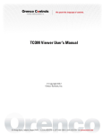
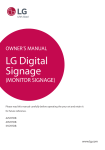
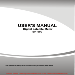
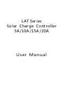
LAT Ser ies
So lar Char ge Cont roller
5A /10A /15A /20A
User Manual
Solar Charge Controller LAT05/10/15/20 User Manual
Sol ar Charge Con trol ler
3.Starting up the controller
1.Description of Function
LAT series intelligent solar controller is especially for
solar photovoltaic power generation system.
It comes with a number of outstanding features,
such as:
●12V/24V automatic recognition
●Clear readable display of charge/discharge and error
description
●Four stages charge way: fast, boost, equal, float
●Temperature compensation
●Low voltage disconnected reulated by state of charge
●Max. 16mm² binding clamp
●Full automatic electronic protect function
This manual provides some important
recommendations related to the controller, including
installation, use, programming and fault exclusion.
2.Safety instructions and waiver of liability
3 . 1Sel f Te s t
As s o on as t h e c on t roll e r is s u ppl i e d with b att e r y, it
s t a r ts a s elf test routin e . Then the display change s t o
normal operation .
3.2Syst e m Vo lt a ge
The controller a djusts its e lf automatically to 12 V or
24V system v ol tage. A s s oon as the batter y vol t a g e at
the ti m e of star t- up is wit h in 10V t o 16V, t h e c on t roll e r
im p lies a 12V sy s tem, el s e if the batter y v ol t a g e is
wit h in 2 0V to 30 V,the controller i mpl i e s a 2 4 V s y stem.
If t h e ba t te r y voltage is not withi n the no r ma l
operatin g r a n g (ca. 1 0 to 1 6 V or ca.20 t o 30V)at star t- u p,
a status d i splay accordi n g t o the section 5 . 2 Error
desc r iption o c cur.
3.3Batter y Type
The LAT seri e s c on t rol ler appl i es to L iq u id and Gel
ba t te r y, the facto r y d e fault set t ing is s u i table for l i qu i d
ba t te r y.
4.Display Functions
The controller is equipped with 5 LEDS.
2.1 Safety
①The solar charge controller may only be used in PV
Charge/Discharge display
systems in accordance with this user manual and the
specifications of other modules manufacturers. No
Battery Capacity display
energy source other than a solar generator may be
connected to the solar charge controller.
Load status display
②Batteries store a large amount of energy, never short
circuit a battery under all circumstances. We strongly
recommend connecting a fuse directly to the battery to
protect any short circuit at the battery wiring.
③Batteries can produce flammable gases. Avoid making
sparks, using fire or any naked flame. Make sure that the
In normal operation,the controller shows charge or
discharge status、battery capacity and load status.
battery room is ventilated.
4.1Charge display(Green LED):
④Avoid touching or short circuiting wires or terminals.
Be aware that the voltages on special terminals or wires
can be as much as twice the battery voltage. Use
Solar array supplies electricity
(LED is on)
isolated tools, stand on dry ground, and keep your
hands dry.
Solar array does not supply electricity
(LED is off)
4.2Status of charge display(Yellow LED):
⑤Keep children away from batteries and the charge
controller.
2.2 Liability Exclusion
The manufacturer shall not be liable for damages,
especially on the batter y, caused by use other than
as intended or as mentioned in this manual or if the
recommendations of the batter y manufacturer are
neglected. The manufacturer shall not be liable if
there has been ser vice or repair carried out by any
<25%
25-75%
>75%
The percentage corresponds to the available energy
until low voltage disconnect in relation to a fully
charged batter y.
4.3Load status display(Red LED):
In case of deep discharge or overload/short-circuit
of load, the load output is switched off.
unauthorized person, unusual use, wrong
installation, or bad system design.
Low voltage
Overload or short-circuit
Normal operation
disconnect(LED is on) of load(LED is flashing)
(LED is off )
Page 1 of 3 pages
Solar Charge Controller LAT05/10/15/20 User Manual
5.Safety Features and Error description
5.1 Safety features
Solar terminal Battery terminal Load terminal
Reverse
polarity
Protected *1 Protected *1
Short circuit Protected
Protected *3
Protected
Over voltage Max.55V *4
Max. 40V
Under
voltage
Over temp.
Switches off
immediately
Switches off
with delay
Over current
Reverse
Current
Protected *2
6.Low Voltage Disconnect Function
The controller uses state of charge to protect the
batter y form being deeply discharged:
11.2V/22.4V~11.8V/23.6V.
Disconnect at 11.2V/22.4V(at nominal load current)
up to 11.8V/23.6V(at no load current).
1.If the controller goes into low voltage protection, it
will restore only when the battery being recharged and
the voltage reaching the reconnect voltage.
2.Around oblique line value separately on behalf of
12V and 24V system's value.
7.Mounting and Connecting
Switches off
switches off the load if the temperature
reaches the set value.
*1 Controller can not protect itself in a 24V system when
polarity of battery or solar is reversed.
*2 Controller can protect itself, but loads might be damaged.
*3 Battery must be protected by fuse, or battery will be
permanently damaged.
*4 The solar panel voltage should not exceed this limit for a
long time as voltage protection is done by a varistor.
Warning: The combination of different error
conditions may cause damage to the controller.
Always remove the error before you continue
connecting the controller.
The controller is intended for indoor use only.
Protect it from direct sunlight and place it in a dr y
environment. Never install it in humid rooms(like
bathrooms). The controller measures the ambient
temperature to determine the charging voltage.
Controller and batter y must be installed in the same
room. The controller warms up during operation,
and should therefore be installed on a non
flammable surface only.
Remark: Connect the controller by following the
steps described below to avoid installation faults.
①
5.2 Error description
Error
Loads
are
not
supplied
Display
Battery is
not being
charged
during
the day
Remedy
Batter y is low
Load will reconnect
as soon as battery
is recharged
Over current/
short circuit
of loads
Switch off all loads.
Remove short
circuit.
Batter y has
low capacity
Change batter y
Red LED
is on
Red LED
is flashing
Battery is
empty after
a short time
Reason
Red LED
is on
Solar array faulty
Green LED or wrong polarity
is off
Batter y voltage
over
voltage
protection
Does not
recognize
the system
voltage
too high
(>15.5V/31V)
Remove faulty
connection/
reverse polarity
Check if other
sources overcharge
the battery.
If not, controller
is damaged.
Red and
Yellow LED
Battery wires or
(the right
Check batter y
battery fuse
side) are
wires,fuse and
damaged, battery
lighted
batter y.
has high resistance
The batter y
voltage is not
Charge or discharge
All LED within the normal the battery to make
the voltage within
Lighted operating rang
at start-up
the normal range
Mount the controller to the wall
with screws that fit to the wall
material.
Use screws with max.4mm shaft
and max.7.5mm head diameter,
no counter sunk .
Mind that the screws have to
carr y also the force applied by
the wiring.
②
Connect the wires leading to
the batter y with correct
polarity. To avoid any voltage
on the wires, first connect the
controller, then the batter y.
We strongly recommend
connecting a fuse directly to
the batter y to protect any
short circuit at the batter y
wiring.
The fuse must take the charge controller nominal
current:
LAT05: 20A;
LAT10/15: 30A;
LAT20: 40A.
Mind the recommended wire length:
Min 30cm to max 100cm.
The wire size:
LAT05: min2.5m m 2
LAT10: min6m m 2
LAT15/20: min10m m 2
Warning: If the battery is connected with reverse
polarity, the load terminals will also have the wrong
polarity. Never connect loads during this condition.
Page 2 of 3 pages
Solar Charge Controller LAT05/10/15/20 User Manual
③
Connect the wires leading to
the solar array with correct
polarity, to avoid any voltage
on the wires, first connect the
controller then the Solar array.
Mind the recommended wire size:
2
LAT05: min 2.5 m m
LAT10: min 6 m m 2
2
LAT15/20: min 10 m m
8.Grounding the Solar System
Be aware that the positive terminals of the controller
are connected internally and therefore have the same
electrical potential. If any grounding is required always
do this on the positive wires.
Remark: Place positive and negative wire close to
each other to minimize electromagnetic effects.
Solar panels provide voltage as soon as exposed to
sun light .Mind the solar panel manufacturer ’s
recommendations in any case.
④
Connect the wires leading to the
loads with correct polarity.
To avoid any voltage on the
wires, first connect the wire to
the load, then to the controller.
Remark: If the device is used in a vehicle which has the
battery negative on the chassis, loads connected to
the controller must not have an electric connection to
the car body, otherwise the Low Voltage disconnect
and electronic fuse functions of the controller are
short circuited.
Mind the recommended wire size:
2
LAT05: min 2.5 m m
LAT10: min 6 m m 2
2
LAT15/20: min 10 m m
9.Technical Data
Model
LAT05
LAT10
System voltage
12V/24V automatic recognition
Max. solar current or load current
5A
Fast voltage
14.0V/28.0V(25℃)
10A
Boost voltage
14.5V/29.0V (25℃)
Equalization voltage
14.8V/29.6 V (25℃)(Liquid)
Float voltage
13.7V/27.4 V (25℃)
Load disconnect voltage
11.2~11.8V/22.4~23.6V
Load reconnect voltage
12.5V/25.0V
LAT15
LAT20
15A
20A
Battery type
Liquid、Gel
Temperature Compensation
-4.17 mV/K per cell(Boost, Equalization); -3.33 mV/K per cell(Float)
Max. solar voltage
55V
Max. ba ttery voltage
40V
Over voltage protection
15.5V/31.0V
Dimensions/ Weight
81*102*37 / 150g
Wire size
16mm²(AWG#6)
Own consumption
4mA
Ambient temperature
-40 ~ +60 ℃
Degree of protection
IP22
Subject to change without notice. Version: DC14
Page 3 of 3 pages